

Page 1

1
5
.
2
2015
VERSION
© TechnoKom
Page 2

AutoGRAPH-GSM • USER MANUAL
2
TechnoKom © 2015
Page 3

AutoGRAPH-GSM • USER MANUAL
3
TechnoKom © 2015
Table of contents
Software Copyright Notice ............................................................................................................................... 4
Introduction ............................................................................................................................................................5
Safe Operation Recommendations ............................................................................................................ 6
Product Overview ................................................................................................................................................ 7
Technical Specications ................................................................................................................................... 8
Scope of Supply ................................................................................................................................................ 10
Components of AutoGRAPH-GSM Controller (standard case) .....................................................11
Components of AutoGRAPH-GSM Controller (protective case) .................................................. 12
Interface Connectors ..................................................................................................................................... 13
Structure Diagram of AutoGRAPH-GSM (GPS/GLONASS) .......................................................... 16
Brief Description of Vehicle Tracking System Operation ................................................................ 22
Connection of AutoGRAPH-GSM controller .......................................................................................... 25
Installation of SIM Card ................................................................................................................................. 26
Installation of MicroSD Card ........................................................................................................................ 27
Connection of GPS/GLONASS Antenna ................................................................................................ 28
Connection of GSM Antenna ....................................................................................................................... 29
Power Supply Connection ............................................................................................................................ 30
Backup Power Supply Connection ............................................................................................................ 31
Connection of Digital Inputs 1...4 (active low) ...................................................................................... 32
Connection of Digital Inputs 7...8 (active high) .................................................................................... 35
Connection of Analogue Inputs................................................................................................................... 37
Connection of High-impedance Digital Input ........................................................................................ 39
Connection of Outputs.................................................................................................................................... 40
1-Wire .................................................................................................................................................................... 41
RS-232 (EIA / TIA-232-E) ............................................................................................................................. 42
RS-485 (TIA / EIA-485-A) ............................................................................................................................. 44
CAN Bus (SAE J1939 / FMS) ..................................................................................................................... 47
Connection of Backup Battery ................................................................................................................... 48
Audio Interface .................................................................................................................................................. 49
Indication of Operation .................................................................................................................................. 50
Drivers Installation ........................................................................................................................................... 53
Connection to PC ............................................................................................................................................. 55
Warranty Provisions (summary) ................................................................................................................. 56
Page 4
AutoGRAPH-GSM • USER MANUAL
4
TechnoKom © 2015
Some functions of AutoGRAPH-GSM Series controllers depend on capacities and conguration of
the existing mobile network operator (MNO). Furthermore, some functions may be disabled by
the operator, or their operating range may be limited due to the settings of the network. To check
availability of a certain function, contact your mobile network operator.
All information on functions, functional capabilities and other specications related to AutoGRAPHGSM Series on-board vehicle tracking controllers, as well as all information contained in this User
Manual is based on current data (at time of writing) and is deemed to be valid as of the date of
publication. Technokom reserves the right to modify the information or specications without prior
notice or commitment.
IMPORTANT
IMPORTANT
Products of TechnoKom referred to in this Manual may incorporate software stored in
semiconductor memory or other media, copyrights to which belong to TechnoKom or third
parties. Laws of the Russian Federation and other countries secure certain exclusive rights
of TechnoKom and third parties to the software, which is subjected to copyright, for example,
exclusive rights for distribution or reproduction.
Therefore, any alteration, reverse engineering, distribution or reproduction of any software
incorporated in TechnoKom products, is prohibited to the extent provided by law.
Furthermore, purchase of TechnoKom products does not imply direct, indirect or other
granting of any licenses related to copyrights, patents and patent applications of TechnoKom
or any third party, except for an ordinary, nonexclusive free license for use, which is granted
in virtue of law upon each sale of the product.
Communication protocol between AutoGRAPH-GSM Series on-board vehicle tracking
controllers and communication data server is considered to be condential information and
intellectual properly of TechnoKom.
The communication protocol between the AutoGRAPH-GSM Series on-board vehicle tracking
controllers and a communication data server shall be transferred by TechnoKom to integrators
and software manufacturers only upon signing the Condentiality Undertaking.
Unauthorized distribution of protocol being used for communication between AutoGRAPH-
GSM Series on-board vehicle tracking controllers and communication data server is strictly
prohibited.
Software Copyright Notice
Page 5
AutoGRAPH-GSM • USER MANUAL
5
TechnoKom © 2015
This User Manual applies to AutoGRAPH-
GSM Series on-board vehicle tracking
controller (hereafter - tracker) of hardware
revision 3.0 produced by TechnoKom Ltd1.
It contains installation and connection
procedures of this device, as well as its
function and control. This Manual constitutes
the Operating Rules to be observed to ensure
successful operation of the controller and its
compliance warranty provisions.
The Manual is intended for specialists who
are aware of maintenance and installation
principles typical for motor vehicles and are
procient in using the electronic and electrical
equipment of various vehicles.
To ensure the best performance of the
AutoGRAPH-GSM controller, they should
be installed and set up only by qualied
specialists.
For proper operation of the
AutoGRAPH-GSM controller, a user
should be aware of operating principles
of the vehicle tracking system as a whole,
as well as understand functions of its
individual components. Therefore, it is highly
recommended to study the fundamentals
of operation of GPS navigation, GSM
communication, peculiarities of short
message service (SMS), GPRS and the
Internet before starting.
Introduction
Version history
This table provides a summary of the document revision
Version Description Date
15.0 Initial release for AutoGRAPH-GSM 3.0. 12/2014
15.1 Added information on the AutoGRAPH-GSM+ modication 12/2014
15.2 Added correct structure diagram on p.16 02/2015
1
The AutoGRAPH-GSM on-board trackers of hardware revision 3.0 have been produced
from serial number 0360001.
Page 6

AutoGRAPH-GSM • USER MANUAL
6
TechnoKom © 2015
This section contains important information
for effective and safe operation. Please
read the information below before using
AutoGRAPH-GSM on-board vehicle tracking
controllers.
Performance Characteristics
AutoGRAPH-GSM on-board vehicle tracking
controllers operate using a GSM/GPRS
module and function as a low power receiver
and transmitter. When the device is ON,
it receives and transmits electromagnetic
energy in the radiofrequency range.
Operating band of the device ranges from
900 MHz to 1,990 MHz; the device uses
digital modulation techniques.
When the device is in operation, a call service
system controls the strength of sent-out RF
signal.
Exposure to Electromagnetic
Fields
The design of the AutoGRAPH-GSM onboard vehicle-tracking controller complies
with the following standards, which specify
the safe levels of exposure to radiofrequency
electromagnetic elds:
• EN 55022: 2010+AC:2011 / Class B
Information technology equipment. Radio
disturbance characteristics. Limits and
methods of measurement.
• EN 55024:2010 Information technology
equipment. Immunity characteristics. Limit
and methods of measurement.
• EN 61000-3-2:2006+A1:2009+A2:2009/
-3:2008 Electromagnetic compatibility
(EMC) Limits.
• EN 61000-6-3:2007+A1:2011
Electromagnetic compatibility (EMC)
Generic standards.
• EN 301 489-1 Electromagnetic
compatibility and radio spectrum Matters
(ERM); Electromagnetic Compatibility
(EMC) standards for radio equipments and
services.
Safe Operation Recommendations
Antennas
Use only original supplied antennas.
Antennas that have been modied may
damage the device or cause violations of
statutory rules and regulations.
DO NOT touch the GSM antenna of the
device while it is in operation. This can impair
communication quality and give rise to an
undesired increase in radiated power.
DO NOT touch the GPS antenna of the
device while it is in operation. This can
impair the quality of reception and result in
inaccurate positioning.
DO NOT use a device with a defective
antenna. If there are any defects in antenna
or antenna cable, replace the antenna or
consult your local dealer as soon as possible.
Electromagnetic Interference and
Compatibility
Almost any electronic device is subjected
to electromagnetic interference unless it is
adequately shielded, has proper construction
or is compatible with devices operating in
another frequency band.
Prohibition on Use of Mobile
Communication Devices
If you come across a signage or a notice, which
prohibits the use of mobile communication
devices, turn off your tracker. This is required
to avoid electromagnetic interference with
equipment sensitive to electromagnetic
elds often used in hospitals, health care
institutions or petrol stations.
Medical Devices
Cardiac Pacemakers
Medical Device Manufacturers Association
advises to use mobile communication devices
at distances greater than 15 cm from cardiac
pacemaker so as to prevent the failure of
the latter. These recommendations conform
to the studies carried out by independent
Page 7

AutoGRAPH-GSM • USER MANUAL
7
TechnoKom © 2015
medical laboratories and Research Centre
for Wireless Technologies.
Hearing Devices
Sometimes, use of mobile communication
devices may cause troubles for wearers of
certain hearing devices. In this case, consult
the manufacturer of your hearing device to
select another model.
Other Medical Devices
For other personal medical devices, contact
your physician or device manufacturer to
nd out whether your device is adequately
shielded from electromagnetic interference
generated by mobile communication devices.
General Information on Safe Use
Vehicle
Observe the rules on using hand-held
devices when driving.
• Use hands-free devices when driving.
• Stop to make or take a call.
Product Overview
The AutoGRAPH-GSM Series on-board vehicle tracking controller is an electronic recorder
which tracks all movements of a vehicle by recording the time and the route in the form
of geographic coordinates received from the satellites of global navigation system GPS
(NAVSTAR) or GLONASS.
In addition to coordinates, the device records a number of other parameters: speed, direction
of movement, event counters, etc., as well as the states of digital inputs of the controller,
external sensors and data buses.
Collected data is transferred by a GSM 900/1800 mobile network operator by means of
General Packet Radio Service (GPRS) to the dedicated server where they become available
via the Internet for further analysis and processing by dispatch software.
The device may be used for any type of vehicles.
Data transfer is possible only when GSM 900/1800 mobile network operator, which supports
General Packet Radio Service (GPRS), is available.
IMPORTANT
Explosion Hazard Zones
SWITCH OFF the device when entering the
explosion hazard zone. Explosion hazard
zones include: fuel stations, box girder decks
on sea vessels, facilities or plants for handling
and storage of fuels or chemicals, areas with
chemicals or solid particles such as grains,
dust or metal powder in atmosphere; and any
other locations where it is usually required to
shut off a vehicle’s engine. Explosion hazard
areas are often (yet not always) expressly
marked.
Blasting Areas
In order to avoid interference with blasting
operations, SWITCH OFF the device in
blasting areas or in any locations marked
with «Two-way radio-communication is
prohibited» signage. Observe the signage
instructions and rules.
Page 8
AutoGRAPH-GSM • USER MANUAL
8
TechnoKom © 2015
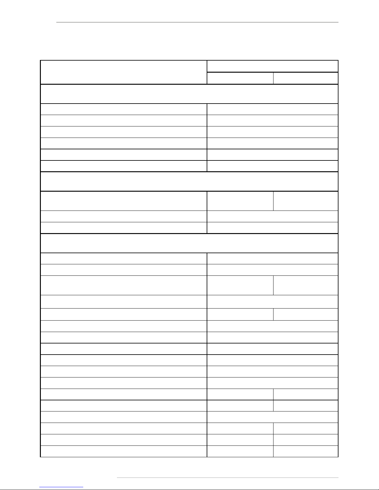
Technical Specifications
Description
Value for AutoGRAPH-
GSM GSM+
GNSS Receiver
Supported GNSS GLONASS + GPS / GALILEO / Beidou
GNSS receiver uBlox MAX-M8Q
Channels 72
A-GNSS service Yes
Differential GPS (D-GPS) Yes
Antenna (GPS/GLONASS) External (SMA)
GSM Module
Communication
GSM
(GPRS / SMS)
3G UMTS1 / GSM
(GPRS / SMS)
SIM card holders 2
Antenna (GSM) External (SMA)
General
Connection to PC USB 2.0
Internal FLASH memory, records > 270.000
Additional memory
External MicroSD
(up to 32GB)
Internal eMMC
(4GB)
Digital inputs, total number 6
High-impedance digital inputs, total number --- 1
Congurable inputs (analogue/digital), total number 2
Digital outputs, total number 2
Built-in accelerometer Yes
1-Wire 1
RS-232 1
RS-485 (TIA / EIA-485-A) 2
CAN (SAE J1939 / FMS) 1 2
Audio interface (GSM) / Loudspeaker amplier No Yes
Type of external backup battery (not supplied) Lead-acid
Rated backup battery voltage 12 / 24 12
Battery Charger No Ye s
Charging time, hours --- 30
Page 9
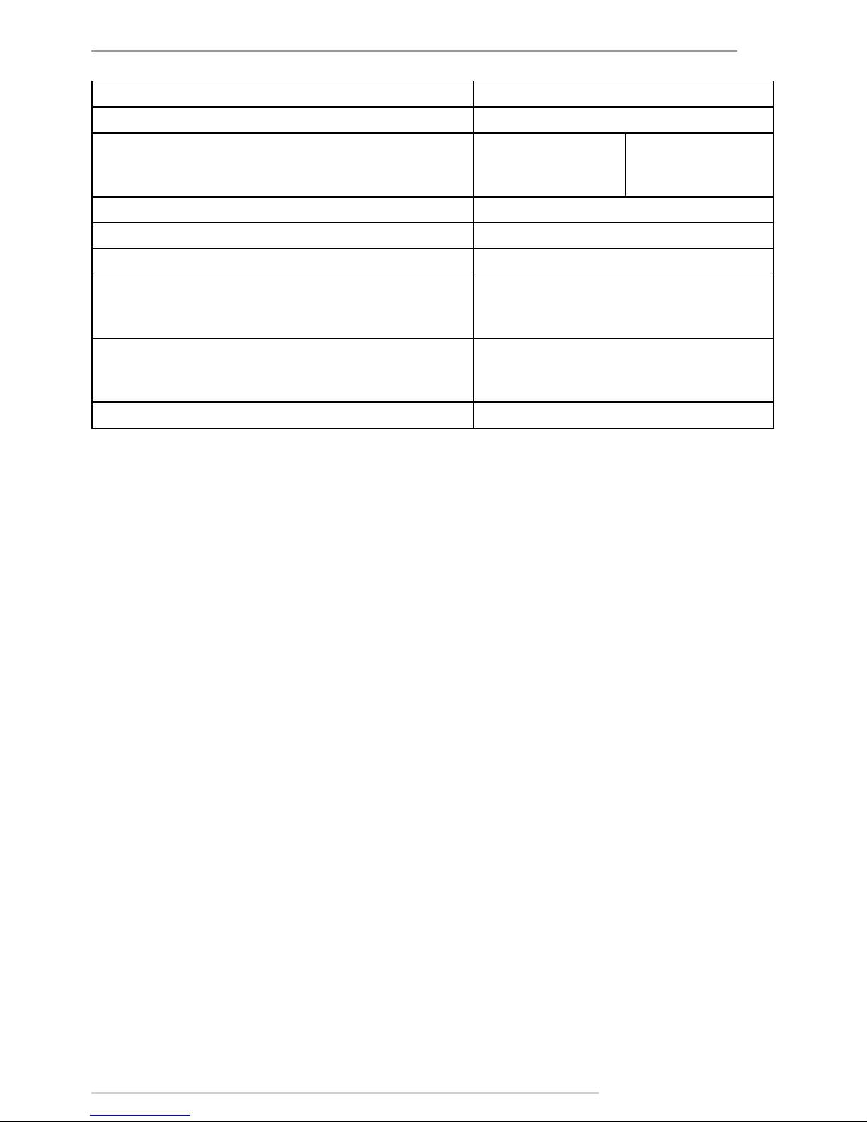
AutoGRAPH-GSM • USER MANUAL
9
TechnoKom © 2015
Operating voltage, V 10...50
Maximum supply voltage, V 60
Power consumption at 12 VDC:
- recording state, mА
- data transferring state, mА
70
300
80
320
Time to rst start2, sec 23
Protective case (IP54) Optional
Operating temperature, °С -40...+85
Dimensions, mm:
- standard case
- protective case
138 х 67 х 27
138 x 92 x 27
Weight, kg:
- standard case
- protective case
0,110
0,150
Average life time, years 10
1
Optional. Specied in «Hardware version» eld.
2
With nominal navigation signals level -130dBm.
Page 10
AutoGRAPH-GSM • USER MANUAL
10
TechnoKom © 2015
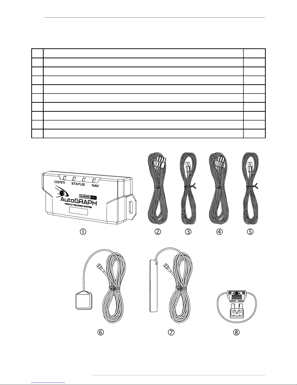
Scope of Supply
№ Description GSM
1 AutoGRAPH-GSM (GPS/GLONASS) on-board controller 1
2 Interface Cable (primary) 1
3 Additional 4/6-pin interface cable 1*
4 6-pin RS-485 / CAN interface cable 1*
5 4/6-pin RS-232 / RS-485-2 interface cable 1*
6 «AGNA-G2» GPS/GLONASS Antenna 1
7 «AGCA-4G» GSM Antenna 1
8 1A fuse with a holder 1
9 Warrantee certicate 1
*on request
Page 11
AutoGRAPH-GSM • USER MANUAL
11
TechnoKom © 2015
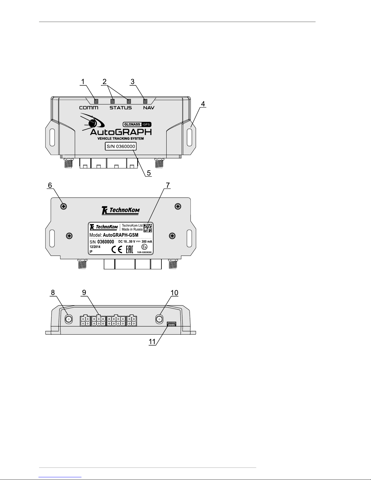
Components of AutoGRAPH-GSM
Controller (standard case)
1. COMM LED (bi-colour).
2. STATUS LEDs.
3. NAVIGATION LED (bi-colour).
4. Mounting bracket.
5. Label with serial number.
6. Fastening screw of a back cover (x4).
7. Manufacturer’s label.
8. GSM antenna
9. Interface connectors.*
10. GPS / GLONASS antenna.
11. Mini USB connector
* For more detailed information on assignment of inter face connectors see «Interface Connectors» section of this User Manual.
Page 12
AutoGRAPH-GSM • USER MANUAL
12
TechnoKom © 2015
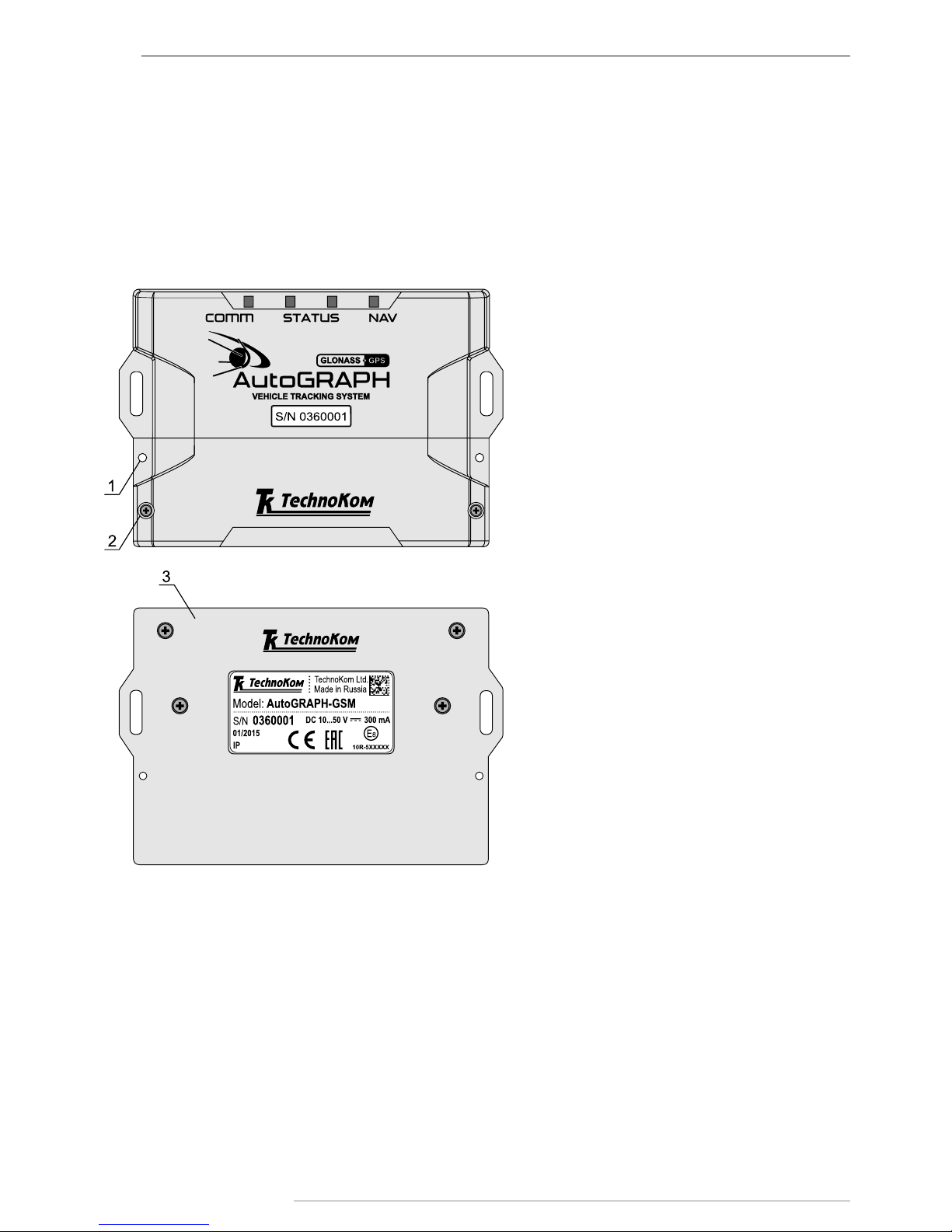
Components of AutoGRAPH-GSM
Controller (protective case)
1. Sealing hole (x2).
2. Fastening screw of a protective cover (x2)
3. Back protective cover.
Optionally, the AutoGRAPH-GSM may be supplied in a protective case providing high ingress
protection rate and sealing option. The protective case has built-in case tamper switch
intended to x any attempts of the case disclosing.
Page 13
AutoGRAPH-GSM • USER MANUAL
13
TechnoKom © 2015
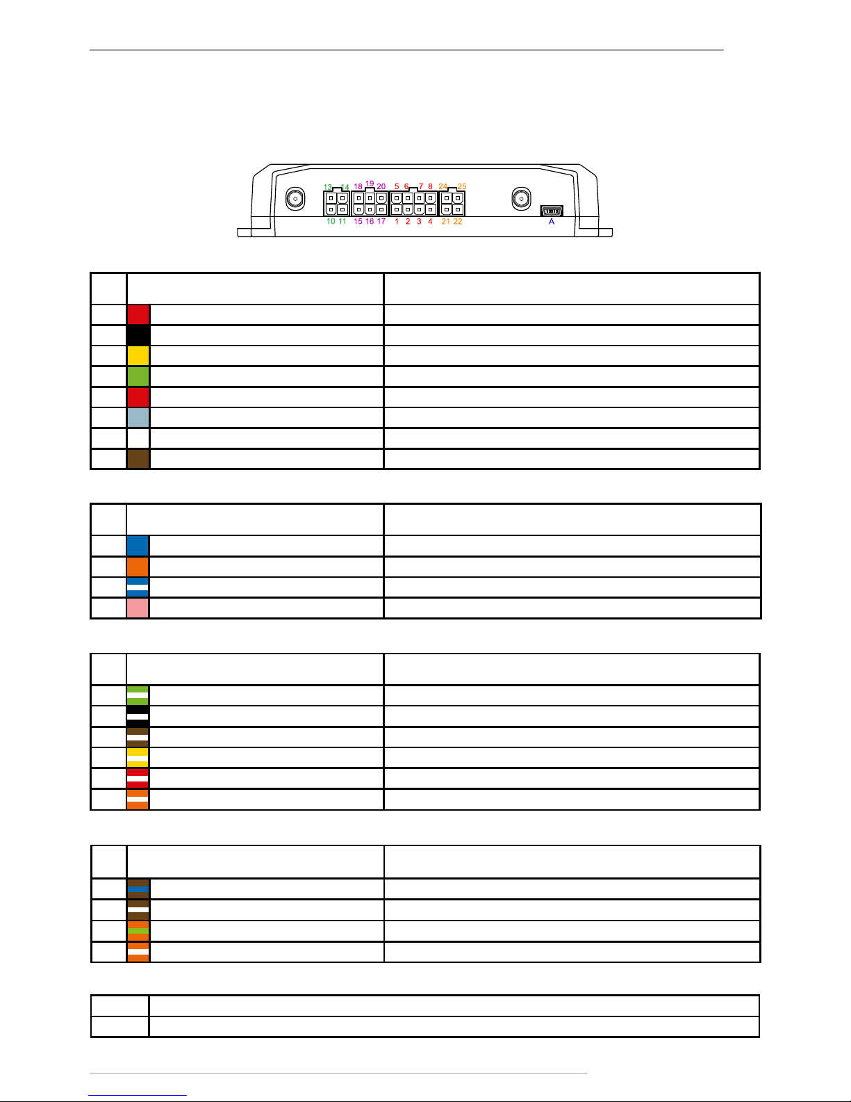
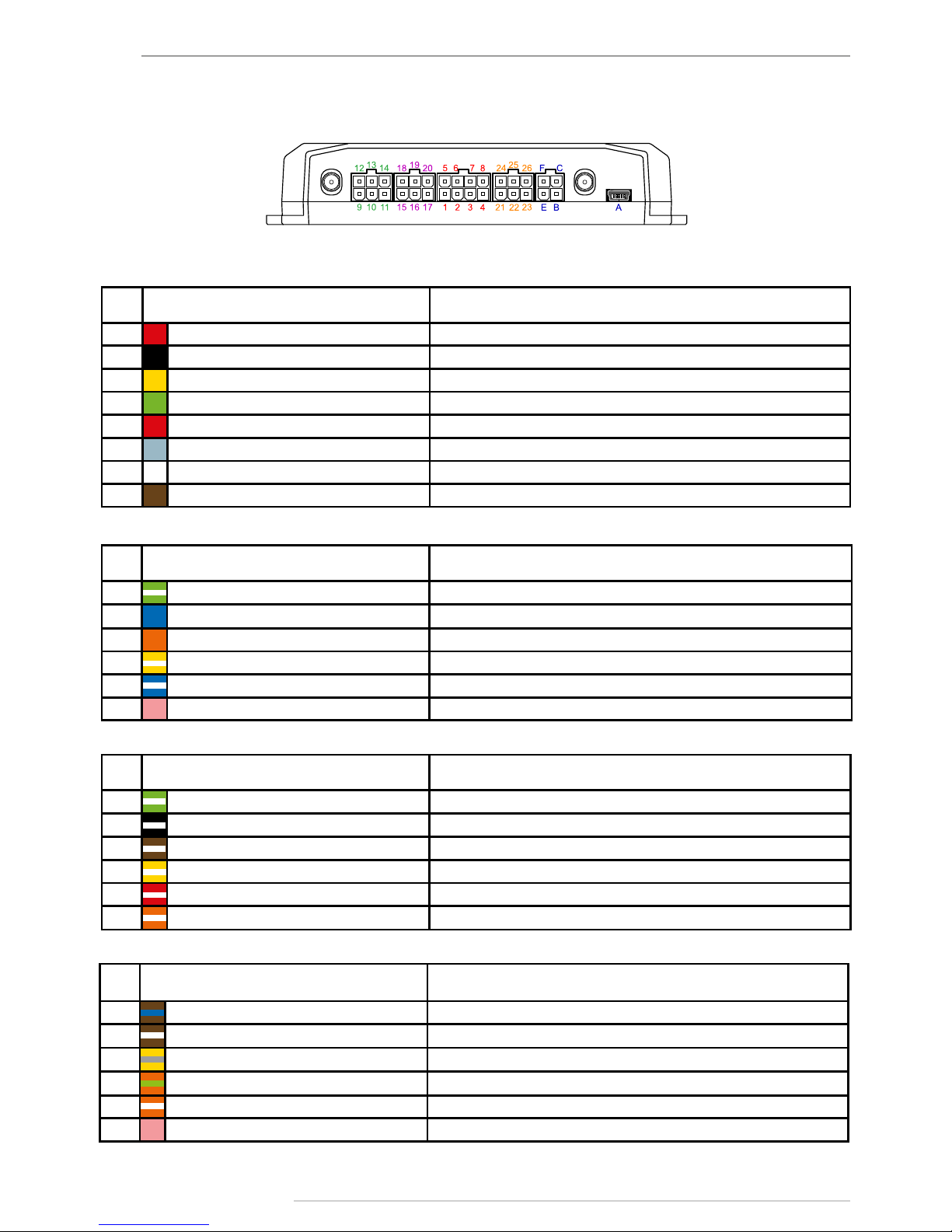
Interface Connectors
AutoGRAPH-GSM (GPS/GLONASS)
Primary interface connector
4-pin interface connector
6-pin CAN / RS-485 interface connector
№ Colour of a wire in a cable Assignment
1 Red (long) + Vin
2 Black -Vin
3 Yellow Digital input 1 (active low)
4 Green Analogue input 1 (0…10 V) / Digital input 5 (active high)
5 Red (short) + Backup supply voltage
6 Gray Open collector output 1 (0.5 А)
7 White Digital input 2 (active low)
8 Brown Analogue input 2 (0…24 V) / Digital input 6 (active high)
№ Colour of a wire in a cable Assignment
10 Blue Digital input 3 (active low)
11 Orange Open collector output 2 (0.5 А)
13 Blue with a white stripe Digital input 4 (active low)
14 Pink 1-Wire
№ Colour of a wire in a cable Assignment
15 Green with a white stripe CAN (H)
16 Black with a white stripe Digital input 7 (active high)
17 Brown with a white stripe RS-485 (B)
18 Yellow with a white stripe CAN (L)
19 Red with a white stripe Digital input 8 (active high)
20 Orange with a white stripe RS-485 (A)
4-pin RS-232 / RS-485 interface connector
№ Colour of a wire in a cable Assignment
21 Brown with a blue stripe RS-232 TxD
22 Brown with a white stripe 2: RS-485 (B)
24 Orange with a green stripe RS-232 RxD
25 Orange with a white stripe 2: RS-485 (A)
Additional connectors
ID Assignment
A Mini USB connector (programming / data reading / GPS mouse)
Page 14
AutoGRAPH-GSM • USER MANUAL
14
TechnoKom © 2015
Primary interface connector
6-pin interface connector
6-pin CAN / RS-485 interface connector
№ Colour of a wire in a cable Assignment
1 Red (long) + Vin
2 Black -Vin
3 Yellow Digital input 1 (active low)
4 Green Analogue input 1 (0…10 V) / Digital input 5 (active high)
5 Red (short) + Backup rechargeable battery
6 Gray Open collector output 1 (0.5 А)
7 White Digital input 2 (active low)
8 Brown Analogue input 2 (0…24 V) / Digital input 6 (active high)
№ Colour of a wire in a cable Assignment
9 Green with a white stripe CAN2 (H)
10 Blue Digital input 3 (active low)
11 Orange Open collector output 2 (0.5 А)
12 Yellow with a white stripe CAN2 (L)
13 Blue with a white stripe Digital input 4 (active low)
14 Pink 1-Wire
№ Colour of a wire in a cable Assignment
15 Green with a white stripe CAN (H)
16 Black with a white stripe Digital input 7 (active high)
17 Brown with a white stripe RS-485 (B)
18 Yellow with a white stripe CAN (L)
19 Red with a white stripe Digital input 8 (active high)
20 Orange with a white stripe RS-485 (A)
6-pin RS-232 / RS-485 interface connector
№ Colour of a wire in a cable Assignment
21 Brown with a blue stripe RS-232 TxD
22 Brown with a white stripe 2: RS-485 (B)
23 Yellow with a grey stripe RPM input*
24 Orange with a green stripe RS-232 RxD
25 Orange with a white stripe 2: RS-485 (A)
26 Pink Digital input 9 (high-impedance)
AutoGRAPH-GSM+ (GPS/GLONASS)
* Unavailable in h/w 3.0
Page 15

AutoGRAPH-GSM • USER MANUAL
15
TechnoKom © 2015
Additional connectors
ID Assignment
A Mini USB connector (programming / data reading / GPS mouse)
B +Microphone signal input
C Loudspeaker signal output (2.65 W amplier)
E Ground
F Call / Answer button input
Page 16
AutoGRAPH-GSM • USER MANUAL
16
TechnoKom © 2015
Structure Diagram of
4
DIGITAL INPUTS
(active low)
DIGITAL INPUTS
(active low)
AUDIO INTERFACE
*
2xSIM
GLONASS• GPS
RECEIVER
CENTRAL PROCCESSING UNIT
FLASH MEMORY
SD-card / еMMC MEMORY
*
ACCELEROMETER
INPUTS / OUTPUTS
2
ANALOGUE /
DIGITAL
INPUTS
ANALOGUE /
DIGITAL
INPUTS
RPM INPUT
*
RS-232
RS-485 I
RS-485 II
USB
1-WIRE
CAN I
BACKUP BATTERY
CHARGER
*
POWER SUPPLY DRIVER
GSM MODEM / 3G GSM MODEM
*
2
2
DIGITAL
OUTPUTS
CAN II
*
1
DIGITAL HIGH
IMPEDANCE
INPUT*
DIGITAL HIGH
IMPEDANCE
INPUT*
DIGITAL INPUTS
(active high)
DIGITAL INPUTS
(active high)
AutoGRAPH-GSM (GPS/GLONASS)
*Module is built-in only in the AutoGRAPH-GSM+.
IMPORTANT
Page 17
AutoGRAPH-GSM • USER MANUAL
17
TechnoKom © 2015
The GSM modem is intended to provide a
connection between the controller and the
GSM mobile network. The GSM signal is
received and transmitted via an external
GSM antenna. The controller is equipped
with a SIM card to be identied by the GSM
network and to be able to access the services
provided by the mobile network operator. The
GSM modem performs several functions:
• Enables the device to access the GSM
network and to be identied by the network
using the SIM card.
• Enables data exchange (including transfer
of track points) between the AutoGRAPHGSM controller and the server via TCP/IP
through the Internet by means of General
Packet Radio Service (GPRS).
• Enables exchange of information and
control SMS messages and USSD requests
(for example, for subscriber’s personal
account monitoring).
GSM-modem
GPS / GLONASS module
CPU
The GNSS module is designed using a highly
sensitive receiver based on high performance
u-blox M8 engine. It receives coded
signals by means of external active GPS/
GLONASS antenna from the satellites of the
Global Positioning System (NAVSTAR) and
GLONASS, and uses its internal computer
to determine the geographical coordinates
of the receiver position, the exact time,
speed and direction of movement. Received
data is transferred via NMEA protocol from
the GNSS module output to the central
processing unit for further processing.
The u-blox MAX-M8 supports concurrent
reception of two GNSS systems and, as
a result, the information being received is
highly accurate and available even in the
case of very poor visibility of satellites.
The central processing unit is the core of the
AutoGRAPH-GSM controller, which unites
all of the system components together and
ensures their interaction in accordance
with the program stored in the device. The
processing unit is a high-speed single-chip
microcomputer able to perform computations
of at a speed and accuracy level that is
sufcient to meet various navigation and
service challenges. The custom rmware,
developed by TechnoKom specialists,
enables the CPU to receive data from the
different modules of the system, to perform
logical and mathematical processing of
the data and to control the modules as
appropriate. It should be noted that the
functional capability of the controller rmware
is being constantly enhanced and extended
so as to provide users with new and improved
features and options.
Power Supply Driver
The power supply driver with protection
circuits generates all of the necessary
supply voltages for controller components.
The primary power supply input ensures
operation at vehicle system voltage of 1050 V, which makes it possible to use the
controller on the majority of vehicles without
employing any additional voltage regulation.
Furthermore, the power supply driver
protects the controller against polarity
reversal, voltage overload, interference, etc.
A resettable fuse is installed in the supply
circuit of the printed circuit board in order to
provide extra protection.
Page 18
AutoGRAPH-GSM • USER MANUAL
18
TechnoKom © 2015
The Non-Volatile FLASH memory module serves as a black box storage device to store the
collected data. The FLASH memory module is designed to store up to 270,000 records for
up to 10 years – even when the device is powered off. The FLASH memory module in the
AutoGRAPH-GSM is designed to use the ring buffer principle, which means that new records
will be written over the oldest records rst, ensuring that the most recent data is always
available.
The AutoGRAPH-GSM controller is equipped with additional memory to store log-les and
photos from cameras connected to the controller. The AutoGRAPH-GSM controller uses an
external micro SD card to store additional data.
Non-Volatile FLASH Memory Module / Additional Memory
Inputs / Outputs
The I/O block is designed for monitor and measure parameters of external equipment and
devices, as well as for control various actuators and warning devices.
The I/O block is divided into three sections:
Digital inputs.
These inputs have two states: «1» and «0» , and are able to show a change of input state,
count pulses and measure frequency.
The controller has the four active low inputs and 2 active high inputs.
In addition, analogue inputs of the controller can operate as digital inputs with the congurable
switching threshold.
Logic of the discrete inputs operation is shown in the table below:
Physical state of the input
Logic state of
active low input active high input
High (connected to supply voltage) 1 1
Open-Circuit 1 0
Low (connected to ground) 0 0
IMPORTANT
Note that logic states of the two inputs dier in open-circuit state (see the table above).
This must be taken into account when making connections.
Operation modes of the discrete inputs are fully programmable for each input and include:
• Normal input. In this mode, the digital inputs are monitored. When the input state
changes, the time and location data is stored into the device memory. Normal mode is useful
for recording the time of different sensors’ activation and for monitoring the performance of
Long-term exposure of the controller to the maximum values of the supply circuit may cause
irreparable damage to the protection circuits due to overheating or disruption. This may lead to
failure of the device. DO NOT exceed the maximum values stated. Operating voltage range and
maximum supply voltage values are specied in Technical Specications section.
IMPORTANT
Page 19

AutoGRAPH-GSM • USER MANUAL
19
TechnoKom © 2015
equipment and mechanisms, such as an alarm button, oil pressure sensor, ignition system,
passenger presence sensor, security alarm triggering, opening of doors, limit switches of
various special-purpose and construction machinery mechanisms, etc. This mode also
enables the device to perform unscheduled transmission of data to the server via GPRS
upon input state changes, as well as to send an SMS message to the specied phone
number.
• Storage counter. This mode is intended to track the input switching states and to count
various events. This may include counting of pulses from fuel-ow pulse output sensor (of
DRT-5 or VZO type), passenger count, speed sensor, tipper body lift sensor, etc. In storage
counter mode, the number of pulses from each sensor is stored in memory. The location
data is not stored.
• Periodic counter. This mode is intended for counting of pulses within one minute. Periodic
counter mode is used for taking the readings of sensors, which transmit measured values in
pulse bursts in amounts proportional to the measured value. This mode is used, for example,
for fuel level, temperature and engine speed sensors with pulse outputs. This mode does
not involve recording of a track point into the storage memory when the input state changes.
• Frequency. This mode is intended for sensors with frequency outputs. The device is
capable of measuring frequencies of 0 – 2,500 Hz. Frequency measurement mode is used,
for example, for fuel level sensors with frequency outputs, engine and shaft speed sensors,
proximity sensors etc.
High-impedance inputs
Furthermore, the AutoGRAPH-GSM+ controller is equipped with one digital high-impedance
active high input with logic levels independent of the supply voltage of the device connected
to this input.
Analogue inputs
Analogue inputs are designed to measure the signal level generated by analogue sensors
and can be used to measure fuel level in a tank, temperature, pressure and other properties.
The AutoGRAPH-GSM controller is equipped with two 10-bit analogue inputs, which are fully
congurable. Each analogue input of the controller can be set up to record data when the
level of the analogue signal changes by a specied value.
The measuring range of the rst analogue input is 0 to 10 V or 0 to 1023 ADC stages.
The measuring range of the second analogue input is 0 to 24 V (but not more than supply
voltage level of the controller) or 0 to 1024 ADC stages.
Furthermore, the analogue inputs of the controller can be set up to operate as active high
digital inputs with a congurable switching threshold. When an analogue input operates as
a digital one, the controller simultaneously records both analogue data and corresponding
logical state. This allows analogue inputs to be used to measure an analogue value and
detect a threshold crossing (for example, critical pressure level, temperature or fuel level etc.).
Digital outputs
Digital outputs are intended to control any external actuators and turn on warning devices.
The controller has two programmable, open collector, discrete outputs. The outputs are
controlled by an SMS command and can be set up to send a pulse of a specied length or
to switch to specied state. Advanced users can send control commands via the data server.
In simple case, the discrete output can be used to warn about speeding, an entrance or exit
of the geofenced area, etc.
Page 20

AutoGRAPH-GSM • USER MANUAL
20
TechnoKom © 2015
USB Port
The USB port embedded into controller is intended to:
• congure and check the performance of the controller by means of the conguration
program – GSMConf;
• read data from the device so as to deliver them to the AutoGRAPH Dispatch Software;
• update processor microcode (rmware) of the device;
• use the controller in the «GPS mouse» mode.
When using the device as a GPS mouse, the tracker, which is connected to the USB port of
a PC, laptop or PDA with a data cable via virtual serial port (СОМ port), transmits the location
data in RMC format through the NMEA protocol once per second. This enables the users to
locate the object equipped with the AutoGRAPH-GSM using software such as OziExplorer,
Google Earth Plus/Pro, 2GIS for PC 3.0, Garmin, Navitel and many others. For details please
refer to «Using the GPS mouse» document.
CAN Bus (SAE J1939/FMS)
The CAN bus is an industrial network standard primarily designed for interconnection of
various actuators and sensors in a single network. It is used in the automotive industry as a
management and control line. The CAN interface of the controller may be connected to the
CAN bus of a vehicle and is intended for use with SAE J1939 / FMS standard protocol. This
standard is widely used in vehicles of well-known truck manufacturers, such as SCANIA,
MAN, VOLVO, DAF, IVEKO, RENAULT, MERCEDES (DaimlerChrysler), KAMAZ and MAZ
trucks of latest models etc. Advanced users can set up the tracker to receive data in any CAN
protocol using the GSMConf program.
Use of the two-wire CAN bus enables quick connection and allows access to a great number
of parameters directly from the sensors of vehicles.
Using the CAN bus, the following information would become available: vehicle speed, cruise
control status, accelerator pedal position, brakes and clutch switch statuses, fuel consumption,
fuel level in tanks (up to 6 sensors), engine speed, service distance, engine hours, engine
coolant temperature, oil and fuel temperatures, total vehicle distance and vehicle distance
per day and axle weight. Furthermore, it enables monitoring of some custom parameters not
covered by SAE J1939 / FMS standard.
RS-485 (TIA / EIA-485-A)
RS-485 (TIA / EIA-485-A) is a data transfer standard for data transmission via a two-wire
serial channel. This bus serves to simultaneously connect up to 32 different devices and
sensors compatible with the controller’s rmware by two wires.
The controller is equipped with two RS-485 buses. Additional RS-485-2 Bus is designed for
connecting a photo camera to the tracker.
The bus enables users to connect up to 8 fuel level LLS sensors, as well as Escort-TD,
Strela-D485, DUT-E-485, DT7.3-06, UZI-1.х and other sensors, and some extra expansion
modules to extend the controller’s functions, e.g. display for indication and messaging with a
vehicle driver, passenger trafc metering unit, expansion modules for discrete and analogue
inputs, barometrical altimeter, RS-232/RS-485 converters, etc.
The RS-485 port of AutoGRAPH-GSM controllers support MODBUS protocol that enables the
users to connect the controller to the thermal sensors, which transmit data via this protocol.
Page 21

AutoGRAPH-GSM • USER MANUAL
21
TechnoKom © 2015
RS-232 (EIA/TIA-232-E)
RS-232 is a communication standard for serial communication between two devices: the
AutoGRAPH-GSM controller and any external device compatible with the controller’s
rmware.
The AutoGRAPH-GSM controller supports interaction with the external GPS/GLONASS
receiver via NMEA 0183 standard, the CAN-LOG module and the AutoGRAPH-NAVIGATOR
Display via RS-232.
The AutoGRAPH-GSM is equipped with 3-axis digital accelerometer with wide range of
full scales from ±2g to ±16g intended to detect motion, determine the tracker’s orientation,
measure vibration level, etc. The tracker can be set up to send a notication to a preset
telephone number or data to a preset server, when detecting the acceleration exceeding a
preset threshold.
Accelerometer
1-Wire
1-Wire, designed by Dallas Semiconductor Corporation, is a simple and convenient bus
typically used to communicate with small devices and sensors such as digital thermometers,
iButton keys, card readers, and other devices equipped with 1-Wire bus and compatible with
the controller’s rmware.
The AutoGRAPH-GSM+ has a built-in charger to charge an external backup battery. When
the controller is powered by the vehicle power system, the power supply driver turns on the
charger. The controller sends a notication to a preset telephone number when the backup
battery voltage falls below the threshold.
RS-232 (EIA/TIA-232-E)*
Battery Charger*
Audio Interface (with loudspeaker amplier)*
The audio interface provides voice communication between vehicle driver and a dispatcher
via GSM.
The AutoGRAPH-GSM+ is equipped with a loudspeaker, a microphone and an Answer/Call
button to make a two-way voice communication.
A built-in amplier increases the signal amplitude 2.65 times and transfers it into the speaker.
The speaker output, microphone input and pins for connecting an external Answer/Call button
are arranged on the singular 4-pin Mini-Fit connector.
Answering and making a call are performed by means of the button on the loudspeaker.
Furthermore, the controller automatically answers calls coming from numbers those have
masks specied in the controller. For example, if the number «543» is specied, the tracker
will automatically answer a call from all numbers that contain «543».
Page 22

AutoGRAPH-GSM • USER MANUAL
22
TechnoKom © 2015
Brief Description of Vehicle
Tracking System Operation
CSV
DBF
OLE
TXT
RTF
PPT
XML
XLS
ODP
ODS
ODT
TIFF
PNG
JPG
SVG
HTML
Dropbox
FTP
GoogleDrive
SkyDrive
Internet & local area network
Mobile Internet
3G/GPRS (GSM)
WI-FI
DATA SERVER
DATA BASE
DESKTOP SOFTWAREMOBILE APP. WEB-SERVICE
VOICE CALL & SMS
DATA EXPORT & REPORTS
VEHICLES equipped with AutoGRAPH-GSM
GLONASS+GPS
Page 23

AutoGRAPH-GSM • USER MANUAL
23
TechnoKom © 2015
AutoGRAPH-GSM controllers, installed on
vehicle, constantly receive coded signals
from Global Positioning System (NAVSTAR)
and GLONASS satellites. These signals are
used to determine exact coordinates of the
vehicle location.
The coordinates are written to the non-volatile
memory of the AutoGRAPH-GSM controller,
either on a regular basis or adaptively.
Furthermore, the storage memory records
and stores the statuses of various sensors
connected to the tracker or data buses, and
other parameters required by the software.
Either on a regular basis or upon occurrence
of a preset event, the collected data is
transferred to the dedicated AutoGRAPH
server over the Internet using General Packet
Radio Service (GPRS) supported by a GSM
mobile network operator.
The server is a computer running Microsoft
Windows Server with an Internet connection,
permanent IP-address and reliable data
storage device. The server is responsible
for receiving data from AutoGRAPH-GSM
controllers, storing the data and transmission
upon request to the dispatcher stations. Key
les are used to provide data access security
on the server.
Dispatcher workstations are personal
computers or laptops with the AutoGRAPH
dispatch software installed (and with the
key les required for particular vehicles)
that has either Internet access or server
connection via LAN. An Internet connection
and computer with the Dispatch Software
will enable users to obtain data from
anywhere in the world. Easy deployment of
the Dispatch Software without the need to
install third-party database support enables
users to immediately create new dispatcher
workstations with any PC running MS
Windows 2000/XP/Vista/7/8. The number of
workstations is unlimited. Dispatch Software
is completely free of charge and the latest
version may be downloaded from the ofcial
website of TechnoKom: http://www.tk-chel.ru.
Mobile users can easily track vehicle
movement in real-time using WEB based
AutoGRAPH.WEB dispatch software run on
any mobile device connected to the Internet.
Upon the user’s request or on a regular basis
the dispatcher workstation connects with
the server to update data on. Depending on
version of the AutoGRAPH Server Software,
access to the data is provided according
the controller key or the personal login and
password. The received data is stored in a
local folder on the dispatcher workstation
that enables processing of the data without
being connected to the server. Furthermore,
to reduce the web trafc, the dispatching
network may be organized in such a way as
to send any missing data through the Internet
to only one workstation, while all other users
may use these downloaded data via LAN
by retrieving them from the local data folder
of the workstation. The users may use this
data to track the vehicles on a map, browse
through various parameters, events and
readings of various sensors. In addition, it is
possible to generate various types of reports
and charts both for each particular vehicle
and in groups.
To interact with various external applications
and handlers (including 1С), AutoGRAPH
Software incorporates OLE server application
(COM server) which enables data exchange
between AutoGRAPH Software and the
programs written in the majority of existing
programming languages which support OLEenabled data exchange, as well as programs
and systems based on their own embedded
programming language (1С Enterprise, MS
Ofce, various databases, etc.).
Furthermore, there is an option to upload all
tracking data and reports in the form of MS
Excel, DBF and CSV les, as well as to use
an external customizable reporting module
which allows users not only to generate a
large number of reports with fully customized
layout, data and charts to be presented, but
also to save them in many different formats
to enable further processing, sending or
presentation: PDF, Open Ofce ODS, Open
Page 24

AutoGRAPH-GSM • USER MANUAL
24
TechnoKom © 2015
Ofce ODT, MS Excel (OLE), MS Excel
(XML), XML, RTF, HTML, TEXT, CSV, BMP,
JPEG, TIFF, GIF.
Control SMS commands and preset
events enables sending of vehicle location
coordinates and various notication
messages to an ordinary cell phone of GSM
standard by means of SMS messages.
Furthermore, SMS commands can be used
to congure AutoGRAPH-GSM+ tracker
directly from a cell phone or a PDA.
i
NOTE
It should be noted that this brief description covers just one of the simple operation schemes of the
vehicle tracking system based on AutoGRAPH-GSM hardware and software. The device has a range
of customizations available to tailor the product to the users’ needs.
i
NOTE
There are various third-party software solutions that can be interfaced with the AutoGRAPH-GSM,
which may support some specic functionality.
i
NOTE
To obtain detailed information on the implementation of particular features for customization
of the monitoring system in accordance with your needs, please contact your regional authorized
representative of TechnoKom and the manufacturer’s technical support service.
Page 25

AutoGRAPH-GSM • USER MANUAL
25
TechnoKom © 2015
Connection of AutoGRAPH-GSM
controller
This section covers connection procedures of AutoGRAPH-GSM/GSM+ controllers:
• Installation of a SIM card
• Installation of an microSD card
• Connection of a GPS/GLONASS antenna
• Connection of a GSM antenna
• Power supply connection
• Digital inputs connection
• Analogue inputs connection
• Outputs connection
• 1-Wire connection
• RS-485 bus (TIA / EIA-485-A) connection
• RS-232 bus connection
• CAN bus (SAE J1939 / FMS) connection
To make the device ready for the simplest operation scheme it would be sufcient just to
install a SIM card, GPS/GLONASS and GSM antennas, and to connect a device to a power
supply source.
However, the hardware and software of AutoGRAPH-GSM controllers includes an extensive
range of features and capabilities, which allow for easy conguration, customization and
adaptation of the system to the needs of the user.
Application of digital and analogue inputs, outputs and data buses enables permanent
monitoring of various parameters (for example, fuel consumption and fuel level), as well as
to monitor operating conditions and performance of external equipment and devices and to
promptly respond to various events (for example, to the pushing of an alarm button). The
output of the controller enables the device to control various actuators and warning devices.
An external backup battery enables the controller to operate even when the main power fails.
All of these features allow the creation of diverse variants of the system able to perform
monitoring of a great number of parameters and to respond to various events.
The following sections focus on basic connection diagrams of various interfaces, inputs and
outputs of the AutoGRAPH-GSM controller.
Page 26

AutoGRAPH-GSM • USER MANUAL
26
TechnoKom © 2015
Installation of SIM Card
The AutoGRAPH-GSM controller is equipped with a dual SIM holder.
To insert SIM cards:
• Unscrew the four fastening screws and remove the back cover of the tracker.
• Insert a SIM card in the lower retaining slot of the SIM card holder with the card’s contacts
facing the PCB (see g.1). Be sure that the card’s keying matches the key on the PCB (see
g.2).
• If necessary, insert a second SIM card in the upper retaining slot of the SIM card holder
with the card’s contacts facing the PCB (see g.3). Be sure that the SIM card is inserted into
the retaining slot with its cut angle facing the edge of the printed circuit board (see g.4).
• When the SIM cards are connected place the back cover back and tighten the four
fastening screws.
The SIM card installed in the lower retaining slot of the SIM card holder is the main card.
When switched on, the AutoGRAPH-GSM controller will operate with this SIM card. The SIM
card installed in the upper retaining slot of the SIM card holder is the backup card. The tracker
will switch to the backup SIM card when the main card is unavailable (disabled, damaged or
not inserted).
For proper operation it is quite sufcient to insert the main SIM card into the tracker. But the
backup card provides the appropriate operation of the controller even if the main SIM card is
damaged. Due to this the controller will stay connected and be able to transfer data full time.
Do a test of a new SIM card in a cell phone before you install it into the controller. This ensures that
GPRS / SMS / USSD services are enabled and operate properly, the PIN code matches the code preset in
the controller (in order to prevent locking), and a personal account associated with the SIM card has
the sucient balance for successful operation of the services.
IMPORTANT
Page 27

AutoGRAPH-GSM • USER MANUAL
27
TechnoKom © 2015
Installation of MicroSD Card
The AutoGRAPH-GSM controller is equipped with a microSD card slot located on the upper
side of the PCB. The microSD card is used to store photos from cameras connected to the
tracker. The tracker supports operation with microSD cards with maximum capacity of 32GB.
To insert microSD card:
• Unscrew the four fastening screws and remove the back cover of the tracker.
• Insert a microSD card in the slot with the card’s contacts facing the PCB (see g.1).
• When the microSD card is inserted, place the back cover back and tighten the four
fastening screws.
To remove the microSD card, gently push the card’s external edge and release it. Then
remove the card.
Page 28

AutoGRAPH-GSM • USER MANUAL
28
TechnoKom © 2015
Connection of GPS/GLONASS
Antenna
The controller is supplied with magnetic mounted waterproof, active GPS/GLONASS antenna.
The GPS/GLONASS antenna is connected to the connector in the lower-right part of the
AutoGRAPH-GSM controller.
The position of the GPS/GLONASS antenna is critical to goof performance of the GPS
receiver, therefore it is highly recommended to plan the antenna’s position on a vehicle before
installation.
The antenna should be located in an open area, which shall ensure free GPS signal
transmission; its active surface should face the sky and be parallel to the celestial sphere.
Possible variants are illustrated in the picture below:
1. The recommended position for
GPS/GLONASS antenna location
2. A possible position for GPS/
GLONASS antenna location
3. Un-recommended position for
GPS/ GLONASS antenna location
When locating the antenna make allowance for the length of its cable. When laying the cable, avoid
sharp edges. Cable bend radius should be at least 10 cable diameters (about 3…5 cm).
Do not x antenna before you make settings and congure your system, it is highly recommended
to determine its nal position and install only when you are absolutely sure that the system is
congured and operates properly.
Do not splice or cut the antenna cable.
i
NOTE
IMPORTANT
Page 29

AutoGRAPH-GSM • USER MANUAL
29
TechnoKom © 2015
Connection of GSM Antenna
The AutoGRAPH-GSM controllers are supplied with a at GSM antenna. The antenna has an
adhesive coating for it to be stuck to the window.
The GSM antenna is connected to the connector in the lower-left part of the controller.
The position of the GSM antenna is critical to good performance of the GSM and GPRS
communication; therefore it is highly recommended to plan the antenna’s position on a vehicle
before installation.
The antenna should be located in an open area, which shall ensure free GSM signal
transmission.
Wipe the window surface with the cloth supplied with the antenna before you attach the
GSM antenna. If antenna is supplied without a cloth, clean the window surface with any cloth
damped with alcohol-based liquid before sticking the antenna.
When locating the antenna make allowance for the length of its cable. When laying the cable, avoid
sharp edges. Cable bend radius should be at least 10 cable diameters (about 3-5 cm).
Do not x antenna before you make settings and congure your system, it is highly recommended
to determine its nal position and install only when you are absolutely sure that the system is
congured and operates properly.
i
NOTE
Do not splice or cut the antenna cable.
In order to avoid cross-talk eects place the GSM and GPS/GLONASS antennas at least 50 cm away from
each other.
IMPORTANT
IMPORTANT
Page 30

AutoGRAPH-GSM • USER MANUAL
30
TechnoKom © 2015
Power Supply
Connection
The AutoGRAPH-GSM controller is
connected to the power supply source
through the interface cable supplied with the
device. The device is supplied with a fuse
intended to provide a short circuit protection
of power supply. The fuse holder is installed
on a wire ring, which should be cut before
operation.
When making connections, pay special
attention to the safety rules stipulated by
the regulations for motor vehicle repair
procedures. All connections should be
properly isolated and securely connected. If
the wire is too short, it can be spliced with
a wire of at least 0.5 mm2 cross section (20
AWG or thicker).
The power supply input of the controller
is rated for the vehicle system operating
voltage of 10-50 V DC.
Power can be fed to the controller either
before or after the vehicle’s battery
disconnect switch:
DISCONNECTING
SWITCH
BLACK (2)
RED (1)
DISCONNECTING
SWITCH
RED (1) BLACK (2)
Power connection before the vehicle battery
disconnect switch
Power connection after the vehicle batter y
disconnect switch
The fuse should be placed as close as possible to the point where the AutoGRAPH-GSM is
connected to the vehicle power system.
ВНИМАНИЕ
If power is connected before the vehicle battery disconnect switch, the controller shall always
be ON, therefore, it is highly recommended to use adaptive position recording for this case so
as to minimize an amount of data to be transferred, as well as to reduce GPRS and web trac.
IMPORTANT
Page 31

AutoGRAPH-GSM • USER MANUAL
31
TechnoKom © 2015
Backup Power
Supply Connection
To avoid the tracker turning off, if the main power supply shuts down, the power supply driver
supports connection of a backup power supply.
Switching between the main power supply and the backup power supply is performed
automatically. If the main power supply turns off, the tracker switches to the backup power
supply. As soon as the main power supply is restored, the controller will switch back to the
main power supply.
The tracker can be setup to send a low voltage notication via SMS to a preset telephone
number, if the backup supply voltage falls below 11 V.
It should be note, that the AutoGRAPH-GSM is not equipped with the battery charger.
Backup Power Connection Diagram:
Page 32

AutoGRAPH-GSM • USER MANUAL
32
TechnoKom © 2015
Connection of Digital Inputs 1...4
(active low)
The AutoGRAPH-GSM controller has four active low digital inputs: two inputs - on primary
interface connector (pin 3, pin 7), two inputs – on additional 4-pin interface connector (pin 9,
pin 11).
Active low digital input has two states:
logical «1» , when the input is connected to the supply voltage or open-circuit.
logical «0» , when the input connected to the ground. This state is considered to be active.
The input is able to show change of the input state, count pulses and measure frequency
and is intended for connection to various dry contact sensors. Ensure that the sensors are
in good order and able to maintain reliable operation. The manufacturer shall not bear any
responsibility for correct state recording of these sensors (chatter, loss of contact and etc.).
It should be noted that all voltage levels of active low digital inputs under 5 V shall be considered to
be logical ‘0’, while all voltage levels above 6 V shall be considered to be logical «1» . If the input is
disconnected it shall denote logical «1» .
It is convenient to connect the active low digital input to an emergency oil pressure relief sensor to
control the engine performance. In this case, the AutoGRAPH dispatch software shall enable metering
of engine hours and application of various lters related to the engine’s operating time. For example,
«Skip the coordinates» lter when the engine is shut down reduces trac and lters coordinate drift
at stops when the engine is not running.
i
NOTE
i
NOTE
Internal Connection Diagram of Active Low Digital Input
Internal connection diagram of the active low digital input is shown in the picture below:
External Connection Diagram of Active Low Digital Input
The external connection diagram for the active low digital input can vary depending on the
position of the vehicle battery disconnect switch in the circuit (see Power Supply Connection
diagrams).
AutoGRAPH-GSM
DIGITAL INPUT
(active low)
LIMIT SWITCH
or SENSOR
Page 33

AutoGRAPH-GSM • USER MANUAL
33
TechnoKom © 2015
RED (1) BLACK (2)
INPUT 1 - YELLOW (3)
INPUT 2 - WHITE (7)
INPUT 4 - BLUE with WHITE STRIPE (13)
INPUT 3 - BLUE (10)
LIMIT SWITCH
or SENSOR
INPUT 1 - YELLOW (3)
INPUT 2 - WHITE (7)
RED (1)
BLACK (2)
LIMIT SWITCH
or SENSOR
INPUT 4 - BLUE with WHITE STRIPE (13)
INPUT 3 - BLUE (10)
DISCONNECTING
SWITCH
DISCONNECTING
SWITCH
Connection Diagram for Active Low Digital Input
«Before Disconnect Switch» Option:
Connection Diagram for Active Low Digital Input «After
Disconnect Switch» Option:
This is due to the fact that when the sensors are connected to the vehicle body (after vehicle
battery disconnect switch option), and the disconnect switch opens; the tracker will not be
able to record sensor states on the digital input 1 correctly.
Page 34

AutoGRAPH-GSM • USER MANUAL
34
TechnoKom © 2015
RELAY or OTHER
INDUCTIVE LOAD
RELAY or OTHER
INDUCTIVE LOAD
INPUT 2 - WHITE (7)
LIMIT SWITCH,
SENSOR or BUTTON
LIMIT SWITCH,
SENSOR or BUTTON
SAFETY RELAY
PROTECTIVE DIODE
+V +V
Connection Diagram for Active Low Digital Input
Inductive Load Circuit:
Sometimes, it is necessary to integrate the controller’s digital input into a circuit with an
inductive load, such as a relay winding, solenoid valve or any other device that has an
inductance coil.
When an inductive load is being disconnected, stored current must be dissipated, this causes
a self-induced electromotive force of inversed polarity (back EMF) that may damage the
controller.
To prevent this, use one of the following protection options if an inductive load is being applied
to the controller:
1. Protective diode (g. 1) – to be installed in parallel to the inductive load. In this case,
forward current of the protective diode (Ifw) should be at least 1.5 • I
holding, coil
. If the coil
holding current is unknown or uncertain, use the option with safety relay protection.
2. Safety relay (g. 2) – to be installed in parallel to the inductive load. In this case, the
safety relay contacts are used for closing the controller’s input on ground.
Fig. 1.
Fig .2.
You may use following protective diodes: KD212, KD116-1 or similar.
Use may use safety relays designed for switching of direct current circuits with voltage
rating compatible with the vehicle system voltage. For example, relays of 901.3747 type
manufactured by AVAR, AO, (www.ellink.ru/co/avar) for a vehicle system voltage of 24 V.
i
NOTE
i
NOTE
Page 35

AutoGRAPH-GSM • USER MANUAL
35
TechnoKom © 2015
Connection of Digital Inputs 7...8
(active high)
AutoGRAPH-GSM controllers have two active high digital inputs, arranged on additional
6-pin CAN/ RS-485 interface connector (pin 14, pin 17).
Active high digital input has two states:
logical «1» , when the input is powered by supply voltage. This state is considered to be
active.
logical «0» , when the input is connected to the ground or open-circuit.
The input is able to show change of the input state, count pulses and measure frequency
and is intended for connection to various dry contact sensors. Ensure that the sensors are
in good order and able to maintain reliable operation. The manufacturer shall not bear any
responsibility for correct state recording of these sensors (chatter, loss of contact and etc.).
Internal Connection Diagram of Active High Digital Input
External Connection Diagram of Active High Input
It should be noted that all voltage levels of digital inputs on «+» under 5 V will be considered to
be logical zero (‘ground’), while all voltage levels above 6 V shall be considered to be logical «1»
(‘+’). If the input is open-circuit it shall denote logical «0» .
i
NOTE
AutoGRAPH-GSM
DIGITAL INPUT
(active high)
LIMIT SWITCH
or SENSOR
+V
LIMIT SWITCH
or SENSOR
+V
+V
INPUT 8 - RED with WHITE STRIPE (19)
INPUT 7 - BLACK with WHITE STRIPE (16)
Page 36

AutoGRAPH-GSM • USER MANUAL
36
TechnoKom © 2015
Connection Diagram for Active High Digital Input Inductive Load
Circuit:
Sometimes, it is necessary to integrate the controller’s digital input into a circuit with
an inductive load such as a relay winding, solenoid valve or any other device, which has
inductance coil.
When an inductive load is being disconnected, stored current must be dissipated, this causes
a self-induced electromotive force of inversed polarity (back EMF) that may damage the
controller.
To prevent such breakdown, use one of the following protection options, if an inductive load
is being applied to the tracker:
1. Protective diode (g. 1) – to be installed in parallel to the inductive load. In this case,
forward current of the protective diode (Ifw) should be at least 1.5 • I
holding, coil
. If the coil
holding current is unknown or uncertain, use the option with safety relay protection.
2. Safety relay (g. 2) – to be installed in parallel to inductive load. In this case, the
safety relay contacts are used for closing the controller’s input on supply voltage.
SAFETY RELAY
PROTECTIVE DIODE
RELAY or OTHER
INDUCTIVE LOAD
+V +V
RELAY or OTHER
INDUCTIVE LOAD
LIMIT SWITCH,
SENSOR or BUTTON
LIMIT SWITCH,
SENSOR or BUTTON
INPUT 8 - RED
with WHITE STRIPE (19)
INPUT 8 - RED with WHITE STRIPE (19)
Fig 1.
Fig 2.
You may use following protective diodes: KD212, KD116-1 or similar.
Use may use safety relays designed for switching of direct current circuits with voltage rating
compatible with the vehicle system voltage. For example, relays of 901.3747 type manufactured by
AVAR, AO, (www.ellink.ru/co/avar) for a vehicle system voltage of 24 V.
i
NOTE
i
NOTE
Page 37

AutoGRAPH-GSM • USER MANUAL
37
TechnoKom © 2015
Connection of Analogue Inputs
The AutoGRAPH-GSM controller has two 10-bit analogue inputs: pin 4 and pin 8 on the
primary interface connector. The analogue inputs allow measurement of voltage levels from
devices with an analogue voltage level output, i.e. signals from an analogue fuel level sensor.
The measuring range of the rst analogue input (pin 4) is 0 to 10 V which is converted to a
gure between 0-1023.
The measuring range of the second analogue input (pin 8) is 0 to 24 V (but not more than
supply voltage) which is converted to a gure between 0-1023.
The input resistance of the analogue inputs is 1 mega-ohm (1MΩ).
The analogue readings are smoothed using the moving average method with a congurable
averaging window.
The cut-off frequency of the input low-pass lter is 1600 Hz.
The analogue inputs of the controller can be used as active high digital inputs with a
congurable switching threshold: analogue input 1 can be set up as digital input 5; analogue
input 2 can be set up as digital input 6. The operational properties of the analogue inputs can
be specied using the GSMConf conguration program or remotely, using the control SMS
commands.
When the analogue input is used as a digital input, it is considered to be open-circuit in the
case of a logical «0» and a voltage below 6 V. In digital mode, the input operates both as
digital input and as analogue input. Along with the current logical state, voltage level on the
input is measured and recorded into the FLASH memory at the specied intervals.
The maximum frequency of the impulse signal on an analogue input in Pulse Counter mode
is 500 Hz.
Connection Diagrams of analogue inputs in digital mode is given in «Connection of Digital
Inputs 7..8 (active high)» section.
Internal Functional Diagram of Analogue Inputs:
10-BIT
ADC
AutoGRAPH-GSM
ANALOGUE INPUT
It is highly recommended to connect analogue inputs to –Vin line, if the inputs are not used.
IMPORTANT
Page 38

AutoGRAPH-GSM • USER MANUAL
38
TechnoKom © 2015
External Connection Diagram of Analogue Inputs:
ANALOGUE INPUT 2 (0..24V) - BROWN (8)
ANALOGUE INPUT 1 (0..10V) - GREEN (4)
BLACK (2)
ANALOGUE
SENSORS
+V +V
ANALOGUE INPUT 2 (0..24V) - BROWN (8)
ANALOGUE INPUT 1 (0..10V) - GREEN (4)
BLACK (2)
ANALOGUE
SENSORS
RELAY
+V+V
VEHICLE SYSTEM VOLTAGE (+)
IMPORTANT
Most analogue sensors are connected to the –Vin line of the vehicle power system. So, if the –Vin
line is disconnected (e.g., by a disconnecting switch), the state of the analogue input will be
undened and analogue readings will not be considered to be valid. Therefore, if the tracker is
connected to the vehicle power system via a disconnecting switch, it is highly recommended to
connect the analogue sensors via a relay.
It is recommended to use a relay intended to switch dc circuits and with operating voltage
equal to voltage of vehicle power system. For example, 901.3747 relay, designed by AVAR Corp.
(www.ellink.ru/co/avar) for 24 V vehicle network.
i
NOTE
Page 39

AutoGRAPH-GSM • USER MANUAL
39
TechnoKom © 2015
Connection of High-impedance Digital
Input
The AutoGRAPH-GSM+ controller has one high-impedance input (pin 26 on the 6-pin
RS-232 / RS-485 interface connector).
It is a high-impedance active high digital input intended to connect a device with a voltage
output to the tracker.
The high-impedance input has two states:
logical “1” – when input voltage is greater than 7 V;
logical “0” – when input voltage is lower than 3 V.
If the high-impedance input is open-circuit it shall denote logical “0”.
Internal Diagram of High-impedance Input:
AutoGRAPH-GSM+ controller
The input resistance of the high-impedance input is 1 mega-ohm (1MΩ).
The cut-off frequency of the input low-pass lter is 5,000 Hz.
Internal Diagram of High-impedance Input:
HIGH-IMPEDANCE INPUT - PINK (26)
Digital voltage
output sensor
+ U sensor
power supply
Page 40

AutoGRAPH-GSM • USER MANUAL
40
TechnoKom © 2015
Connection of Outputs
Internal Diagram of Outputs
External Connection Diagram of Digital Outputs:
The AutoGRAPH-GSM has two open collector digital outputs: the rst output is arranged
on the primary interface connector (pin 6), the second is arranged on the additional 4-pin
interface connector (pin 10).
The outputs are intended to control various external actuators, as well as to activate warning
devices
Minimum recommended load current is 10 mA.
Maximum load current should not exceed 500 mA.
AutoGRAPH-GSM
DIGITAL OUTPUT
The following is an example of a LED and relay connected to the controller output. To
avoid damage of the controller output due to back EMF, induced from disconnecting an
inductive load, connect a protective diode in parallel to the relay. To select a correct diode
make sure that direct current of this protective diode is at least 1.5 times greater than the
relay holding current.
OUTPUT 2 - ORANGE (11)
RELAY
VEHICLE SYSTEM VOLTAGE (+)
OUTPUT 1 - GRAY (6)
TO ACTUATOR
RED (1)
LED
PROTECTIVE DIODE
R
1кОhm*
* Use R = 1 … 2 kОhm, if supply voltage is 24 V.
Use R = 500 Ом … 1 kOhm, if supply voltage is 12 V.
Page 41

AutoGRAPH-GSM • USER MANUAL
41
TechnoKom © 2015
1-Wire
The AutoGRAPH-GSM controller are equipped with a 1-Wire bus intended to connect a touch
memory iButton reader and up to 8 temperature sensors, designed by TechnoKom Ltd. or
DS18B20 thermometers. Furthermore, proximity card readers compatible with the iButton
protocol can be connected to the controller via the 1-Wire bus. This provides supervising
drivers and identication of other staff using individual cards and keys.
Connection Diagram of Touch Memory iButton readers:
Connection of Temperature Sensors Designed by TechnoKom Ltd.:
DATA
GROUND
BLACK (2)
1-WIRE - PINK (14)
BLACK (2)
1-WIRE - PINK (14)
1-Wire data
+V sensor+V sensor
1-Wire data1-Wire data
SENS 1
SENS 2
SENS 8
For detailed information on operation and conguration of the controller for interaction
with the touch memory iButton reader and the temperature sensors via 1-Wire bus see
«1-Wire temperature sensors» document.
i
NOTE
Page 42

AutoGRAPH-GSM • USER MANUAL
42
TechnoKom © 2015
The AutoGRAPH-GSM controller is equipped with an RS-232 (EIA/TIA-232-E) bus.
RS-232 is bi-directional serial data transmission interface between a transceiver and
peripheral devices. The main advantages of the RS-232 interface are reliability, and exibility
of implementation.
RS-232 Serial Connector Pin
Assignment (DE-9):
RS-232 (EIA/TIA-232-E)
Connection Diagram:
1 DCD Not used
2 RxD Receive Data
3 TxD Transmit Data
4 DTR Not used
5 GND System Ground
6 DSR Not used
7 RTS Not used
8 CTS Not used
9 RI Not used
RS-232 «RxD» (24)
ORANGE with GREEN STRIPE
RS-232 «TxD» (21)
BROWN with BLUE STRIPE
The AutoGRAPH-GSM controller supports
interaction with following devices via RS-232
Bus:
1. AutoGRAPH-NAVIGATOR – is a
software-based vehicle tracking system
running on a laptop and designed by
TechnoKom Ltd. When connected to the
controller, the AutoGRAPH-NAVIGATOR
is capable of displaying current position
of the vehicle on a map, monitor of
movement parameters and routing.
Using the AutoGRAPH-Navigator, a
dispatcher can send a list of tasks to a
driver and monitor progress of the tasks.
In addition, the device is capable of
message handling between the driver
and the dispatcher. The AutoGRAPHNAVIGATOR is supplied with a special
connector for connecting to the controller.
2. CAN-LOG 2 (CAN-LOG) – is a device
intended for connecting to the vehicle
CAN Bus, scanning data and transferring
it to another device connected to the
CAN-LOG via RS-232. The CAN-LOG
2 supports many CAN protocols. When
connected to the controller, the CAN-LOG
is capable of reading data from the CAN
bus and transferring it to the controller,
even if the CAN protocol is not known in
advance. The data from the CAN-LOG 2
is transferred in text format.
3. External GPS / GLONASS receiver
with NMEA 0183 standard - is a high-
precision receiver, which allows to acquire
asset position with high accuracy.
RS-232 (EIA / TIA-232-E)
Page 43

AutoGRAPH-GSM • USER MANUAL
43
TechnoKom © 2015
Before connecting any device to the tracker, the RS-232 interface mode must be specied in
the controller. The customer can set this using the GSMConf conguration program or control
commands via SMS or the server.
Connection of CAN-LOG 2 to the controller
Designed by TechnoKom Ltd.:
The following is an example of connection the CAN-LOG 2 module to the tracker. This device
is powered by P145_20 controllers, designed by Farvater Ltd. .
RS-232 «RxD» (24)
ORANGE with GREEN STRIPE
VEHICLE SYSTEM VOLTAGE (+)
CAN-LOG 2
VEHICLE SYSTEM VOLTAGE (+)
RED (1)
BLACK (2)
RS-232 «TxD» (21)
BROWN with BLUE STRIPE
Page 44

AutoGRAPH-GSM • USER MANUAL
44
TechnoKom © 2015
RS-485 (TIA / EIA-485-A)
General Block Diagram of Connection of External Devices
to RS-485 Bus:
The AutoGRAPH-GSM controller is equipped with two RS-485 (TIA/EIA-485-A) interfaces.
RS-485 is one of the most commonly used industrial standards of communication. A network
based on an RS-485 interface consists of transceivers connected with twisted pair wires. All
devices are connected to one twisted pair in the same manner: non-inverting outputs (A) to
one wire and inverting outputs (B) to another wire.
The controller allows up to 16 devices to be connected simultaneously to one RS-485
bus. There are many sensors, interfaces and expansion modules that are compatible with
the tracker’s rmware. Amongst such devices are: fuel level sensors (up to 8 sensors
simultaneously), passenger trafc metering system, input expander, display for messaging
with a vehicle driver, AutoGRAPH-CR device, temperature sensors which support MODBUS
protocol, etc.
The additional RS-485-2 bus is intended for connecting photo cameras to the controller.
Interaction with photo cameras is supported by controllers equipped with additional memory.
The AutoGRAPH-GSM stores photos in an external microSD card.
RS-485-1 «A» (20)
ORANGE with WHITE STRIPE
RS-485-1 «B» (17)
BROWN with WHITE STRIPE
DEVICE (N) DEVICE (2) DEVICE (1)
RS-485-2 «A» (25)
ORANGE with WHITE STRIPE
RS-485-2 «B» (22)
BROWN with WHITE STRIPE
CAMERA (N)CAMERA (2)CAMERA (1)
RS-485-1
RS-485-2
Page 45

AutoGRAPH-GSM • USER MANUAL
45
TechnoKom © 2015
Before making any connections study the manuals for fuel level sensors supplied by the sensor
manufacturers. Pay attention to the supply voltage range of the sensors and peculiarities of
their conguration. Some sensors require external supply voltage stabilization. If you have
any doubts on making connections or conguration, consult the representative of the sensor
manufacturer or your regional TechnoKom dealer.
IMPORTANT
Connection of Fuel Level Sensors to RS-485 Bus
+V sensor +V sensor +V sensor
RS-485-1 «B» (17)
BROWN with WHITE STRIPE
RS-485-1 «A» (20)
ORANGE with WHITE STRIPE
Currently, the AutoGRAPH-GSM controller supports interaction with any fuel level sensors
with an RS-485 interface which use LLS protocol. The following is an example of connection
the TKLS fuel level sensors, designed by TechnoKom Ltd, to the tracker.
RS-485 Bus of the controller has to be customized to interact with fuel level sensors. It can be
performed by means of the GSMConf conguration program and control commands via the data
server or a SMS.
i
NOTE
Page 46

AutoGRAPH-GSM • USER MANUAL
46
TechnoKom © 2015
Connection of AutoGRAPH-CR to RS-485 Bus
The AutoGRAPH-CR is designed for reading RFID and SIM cards. The ID (identication
number) of inserted card is transmitted to the AutoGRAPH-GSM controller via RS-485 bus.
Up to 250 IDs can be stored in the ash memory of the Card reader. Each card can customize
outputs of the card reader when connecting.
For more information on connection and conguration of the tracker for interaction with the
AutoGRAPH-CR via RS-485 bus see «AutoGRAPH-CR User Manual» .
i
NOTE
RS-485-1 «B» (17)
BROWN with WHITE STRIPE
RS-485-1 «A» (20)
ORANGE with WHITE STRIPE
VEHICLE SYSTEM VOLTAGE (+)
AutoGRAPH-CR
All connections should be made when the controller and all external devices to be connected to
the RS-485 bus are disconnected from power supply.
IMPORTANT
Be careful not to cross the «A» and «B» wires, otherwise the device connected to the tracker
may operate incorrectly.
IMPORTANT
Page 47

AutoGRAPH-GSM • USER MANUAL
47
TechnoKom © 2015
CAN Bus (SAE J1939 / FMS)
The AutoGRAPH-GSM controller is equipped with Can Bus (SAE J1939 / FMS) that allows
to connect the tracker to CAN bus of a vehicle and read required data. By default, the tracker
supports SAE J1939 / FMS protocol of CAN. However, advanced users can specify any other
known protocol in the tracker and operate with it. CAN Bus of the tracker can be congured
using the GSMConf program or remotely by means of control commands.
The AutoGRAPH-GSM+ controller is equipped with additional Can Bus (CAN II).
Connection to CAN Bus
(SAE J1939 / FMS)
Typical Vehicle Connectors of SAE J1939-13 Standard
CAN-L (low) (18)
YELLOW with WHITE STRIPE
CAN-H (high) (15)
GREEN with WHITE STRIPE
J
G
C
D
AHB
E
F
J
G
C
D
AHB
E
F
J
G
C
D
AHB
E
F
J
G
C
D
A
H
B
E
F
Pin Assignment (SAE J1939-13)
A Battery (–)
B (+) Unswitched - with Unconditioned 10 A fuse
C SAE J1939 CAN-H (high)
D SAE J1939 CAN-L (low)
E CAN-SHIELD (for SAE J1939-11) or No Connection (for ISO 11783-2)
F SAE J1708 (+)
G SAE J1708 (–)
H Proprietary OEM Use or Implement Bus CAN-H
J Proprietary OEM Use or Implement Bus CAN-L
Page 48

AutoGRAPH-GSM • USER MANUAL
48
TechnoKom © 2015
Connection of Backup Battery
To avoid the AutoGRAPH-GSM+ controller turning off, if the main power supply shuts down,
the power supply driver supports connection of a rechargeable backup battery.
As a backup battery, the tracker uses a lead/acid rechargeable battery of 12 V and 1.2 to 2
Ah capacity.
The AutoGRAPH-GSM+ has a built-in charger to charge the backup battery. The charger
turns on automatically and limits the charging current to 75 mA.
If the backup battery voltage drops below 11 V, the tracker will send a low battery notication
to specied number by SMS.
Switching between the main power supply and the backup power supply is performed
automatically. If the main power supply turns off, the tracker switches to the backup power
supply. As soon as the main power supply is restored, the controller will switch back to the
main power supply.
Connection Diagram of backup battery
The manufacturer recommends using small package lead/acid DT12012 or BPL2-12 batteries
and another battery with capacity not more than 2Ah as a backup power supply. Example of
lead/acid battery is given on the gure.
BACKUP BATTERY
RED SHORT (5)
BLACK (2)
Page 49

AutoGRAPH-GSM • USER MANUAL
49
TechnoKom © 2015
Audio Interface
The AutoGRAPH-GSM+ controller is
equipped with an audio interface that provides
two-way communication between a driver
and a dispatcher. The audio interface consists
of an input for connecting a microphone, an
output for connecting a loudspeaker and an
input for connecting an Answer/Call button.
The audio interface is on the additional 4-pin
audio interface connector.
In order to be able to receive an incoming
call and to make a dialed call, a GS-2 type
loudspeaker, designed by TechnoKom Ltd,
should be connected to the controller. The
loudspeaker with built-in Answer/Call button
should be connected to the 4-pin audio
interface connector.
The AutoGRAPH-GSM+ is equipped with an
audio amplier, which multiplies the output
signal to the loudspeaker 2.65 times.
Receiving an incoming voice call
An incoming call is indicated by producing a
ringtone on the loudspeaker.
To answer the call, press and hold Answer/
Call button on the loudspeaker for 1-2
seconds.
A second press on Answer/Call button ends
the call.
Making a dialed call
To make a dialed call, press and hold
Answer/Call button on the loudspeaker for
1-2 seconds.
The tracker starts to dial to the rst telephone
number, stored in the controllers memory. If
the rst number is not available, the controller
will dial the second preset number. The
tracker will try to call all preset numbers in
order, until one of the numbers answers the
call. If no calls are answered, the tracker will
loop back to the rst number and continue
the dialling process until a call is answered.
A second press on the button ends the call.
Digital input 1 of the controller can be used
for indicating an incoming call using an LED,
or a sound device, connected to this input.
Call indication on digital input 1 should be set
up using the GSMConf program or a control
command.
The tracker can be set up to answer the call
automatically or by pressing the Answer/Call
button on the loudspeaker.
The tracker automatically answers the calls
from telephone numbers, that the auto
answer is enabled for in the tracker’ settings.
To answer calls from other telephone
numbers, press the Answer/Call button.
A press on Answer/Call button must be 1-2 seconds long. A short press won’t be processed.
IMPORTANT
It takes about 30 hours to charge fully discharged 2 Amh capacity battery. So the presented
diagram is not applicable in case of frequently shutdowns of main power supply.
IMPORTANT
Page 50

AutoGRAPH-GSM • USER MANUAL
50
TechnoKom © 2015
Indication of Operation
The AutoGRAPH-GSM has four LEDs arranged on the front side of the tracker and intended
to indicate the tracker operation.
• Bi-colour COMM LED (red / blue) indicates operation of GSM modem.
• STATUS LED1 (green) indicates a state of position acquisition.
• STATUS LED2 (orange) indicates GSM state of data transmission.
• Bi-colour NAV LED (red / green). The LED indicates the GPS/GLONASS receiver mode.
If «GLONASS only» mode is set up, the LED will ash red. If «GPS (NAVSTAR) only»
mode or combined GPS / GLONASS mode is set up, the LED will ash red and green
simultaneously.
Before turning on the AutoGRAPH-GSM, connect GPS / GLONASS and GSM antennas to
the tracker.
Connection Diagram of GS-2 type loudspeaker:
The GS-2 loudspeaker is equipped with micro-jack type connector for connecting a handsfree kit. If the hands-free kit is connected to the loudspeaker, press the answer button on the
hands-free kit to answer an incoming call.
Page 51

AutoGRAPH-GSM • USER MANUAL
51
TechnoKom © 2015
• Power the tracker up.
• Wait until the tracker acquires the position and connects to a GSM. In normal mode, the
COMM LED ashes red every 3 seconds, STATUS LED2 is constantly ON, NAV LED ashes
once a second. The NAV LED ashing colour depends on GPS / GLONASS receiver mode.
• Starting time takes approximately 23 seconds. If the tracker does not start for a long time,
verify compliance with the operating conditions.
Indication of GPS / GLONASS Module Operation:
• When powering up both STATUS LED1 and NAV LED light up and go out after one
second.
• Upon normal operation, the NAV LED ashes once a second. The STATUS LED1 is
constantly green after positioning of the vehicle and goes out upon loss of signal from
satellites.
Indication of GSM Module Operation:
• Searching for a network – the COMM LED ashes red once a second.
• When transferring data to a server - the STATUS LED2 is constantly ON.
• Error of data transmission - the STATUS LED2 ashes twice a second.
• When connecting to GPRS - the STATUS LED2 ashes once per two seconds.
• Normal connection to GSM network – the COMM LED ashes red once every three
seconds.
• Switching off or fault of GSM module – the COMM LED is OFF.
Error Indication:
The NAV LED and the STATUS LED1 can be used for indication of the tracker’s errors. When
an error is detected, the NAV LED lights up in red, the STATUS LED1 ashes green several
times, after that the NAV LED goes out. Number of ashings of the STATUS LED1 determines
an error code.
Number of
ashing
Description of error
1
GSM turning on failure. Ensure, that SIM card is not damaged and correct PIN is
entered
2 FLASH memory failure
3 GSM modem power supply circuit is damaged
4 Tracker rmware is damaged
5 FLASH memory failure. Memory is protected
6 FLASH memory failure. Memory is protected
7 SIM PUK is required
8 SIM is not inserted
Page 52

AutoGRAPH-GSM • USER MANUAL
52
TechnoKom © 2015
Operation with PC:
• Memory cleaning – the bi-colour NAV LED lights constantly red.
• Data reading – the STATUS LED1 is constantly ON.
• Writing the settings – the bi-colour NAV LED frequently ashes red.
When the bi-colour LEDs ashes with two colours simultaneously, the customer will see a mix
of the both colours.
i
NOTE
Page 53

AutoGRAPH-GSM • USER MANUAL
53
TechnoKom © 2015
Drivers Installation
This section covers the procedure of installing the drivers of the AutoGRAPH-GSM controller
for Microsoft Windows 7 OS.
The AutoGRAPH-GSM controller drivers required for Windows 2000, XP, Server 2003, Vista, 7, 8,
Server 2003, Server 2008 (x86 and x64) are free of charge and can be downloaded from the ocial
website of TechnoKom: http://www.tk-chel.ru
i
NOTE
5. Browse to the location where the drivers are saved (Fig.3).
6. Install the driver. When the driver is installed the system will automatically identify
connected device (Fig.4).
7. If necessary, install drivers for the AutoGRAPH CDC device following the outlined
instruction.
8. Drivers for the AutoGRAPH-GSM are successfully installed. The device is ready to
operate with troubleshooting utilities, dispatch software and other applications (Fig.5).
To install the tracker drivers onto Microsoft Windows 7 OS:
1. Connect the tracker to your PC using the interface cable. The system will automatically
search for new equipment (Fig.1). For proper operation, it is sufcient to install drivers for
AutoGRAPH device. The AutoGRAPH CDC drivers are required for the tracker operation
in the GPS-mouse mode.
2. If the Internet connection is available, Windows 7 will automatically connect to
the Windows Update website and install suitable driver for the tracker. If the Internet
connection is not available, continue with the procedure outlined below.
3. Download the archived drivers folder from the ofcial website of TechnoKom AGUSBDriver.zip and extract les to a temporary directory on a hard drive.
4. Launch the driver update wizard and select «Browse my computer for driver software»
to search for drivers manually (Fig.2).
Figure 1. Figure 2.
Page 54

AutoGRAPH-GSM • USER MANUAL
54
TechnoKom © 2015
Figure 3. Figure 4.
Figure 5.
Page 55

AutoGRAPH-GSM • USER MANUAL
55
TechnoKom © 2015
Connection to PC
Some cases may require connection of the AutoGRAPH-GSM controller to a personal
computer (PC) or a laptop. A PC connection may be required for:
• conguration and checking of the performance of the tracker by means of the conguration
program – GSMConf;
• using the tracker in the «GPS mouse» mode;
• reading the data from the tracker storage memory and writing the data directly to the
AutoGRAPH dispatch software.
To connect the tracker to a PC:
• Disconnect the tracker from the vehicle power supply.
• Disconnect the antennas and remove the device from the vehicle.
• Connect the tracker to your PC using a USB cable.
• If the drivers are installed, the system automatically identies the controller. If the drivers
are not installed, install them following the steps specied in the «Installing the drivers»
section.
• The tracker is now ready to operate with the applications.
For detailed information on conguration the tracker using the GSMConf program see
«GSMConf Conguration Program» document.
For more information on reading data from the tracker using the AutoGRAPH Dispatch
Software see «AutoGRAPH Dispatch Software User Manual» document.
i
NOTE
i
NOTE
Page 56

AutoGRAPH-GSM • USER MANUAL
56
TechnoKom © 2015
Warranty Provisions (summary)
TechnoKom, OOO, hereby secures the consumer’s rights granted by local laws within the
Russian Federation and CIS countries, and no other rights.
TechnoKom warrants the AutoGRAPH-GSM controller shall comply with TU 6811-002-
12606363-2013 (Technical Requirements) provided that the customer adheres to the
operating rules set forth in this User Manual.
Warranty period of the device shall be Thirty Six (36) months from the date when the controller
is sold (delivered) to the consumer, but it shall not exceed Forty (40) months from the date of
its manufacture.
If the warranty certicate or other document supporting the fact that the controller has been
sold (delivered) to the customer lacks date of selling, name and ofcial seal of a dealer,
warranty period shall be deemed to start from the date of manufacture of the controller.
Customer shall have a right to repair the product in TechnoKom service centre, if any
workmanship or structural defects are found in the device within the warranty period.
Customer has a right to aftersales service and maintenance within the warranty period.
Customer has any other legal rights stipulated by the legislation of the Russian Federation
and CIS countries laws.
If the cause of breakdown cannot be identied at the moment of warranty claim application, it
is required to carry out the technical expertise, which shall last for 30 days from the date when
the customer les its warranty claim application.
Warranty does not cover any other problems that arise as a result of:
• Violation of transportation, storage and operation rules set forth in this User Manual.
• Unauthorized dismantling of the device if it has guarantee seals and labels.
• Unauthorized repairs or repairs carried out by the third parties within the warranty period.
• Unallowable change of parameters of the external electric power, misuse, abuse or
improper operation of the product as indicated by traces of electrical and/or other damage.
• Unauthorized soldering or unauthorized attempts to connect any leads or other elements
and connectors to a circuit board of the controller as indicated by the corresponding traces.
• Mechanical damage of body or circuit board of the controller, SIM card holder, antennas,
connectors or broken wires.
• Corrosion of external or internal parts or ingress of moisture into the device as indicated
by the corresponding traces.
• Misappropriation or malicious damage of external antenna and cable.
• Damage caused by penetration of foreign objects, contaminants, liquids, or insects into
the device.
• Damages caused by high or low temperature or exposure to intensive microwave radiation.
• Damages caused by nature, re, social factors, casual external factors and unexpected
accidents.
• Damages caused by incompatibility of parameters or incorrect connection of add-on
devices, buses, interfaces and sensors to the controller.
• Operation of the controller at the vehicle system voltage that goes beyond the range
specied in technical specications.
• Damages caused by attempts to congure the controller by means of a third party program.
• Improper functioning due to incompetent or incorrect conguration of the controller, using
either the conguration program or SMS commands.
Page 57

AutoGRAPH-GSM • USER MANUAL
57
TechnoKom © 2015
• Improper functioning due to the fact that a SIM card installed by the customer in the
controller is not subscribed to the following services:
• General Packet Radio Service (GPRS);
• Voice communication;
• reception/sending of SMS messages
or a mobile network operator disabled these services because of negative account balance
of a SIM card or for any other reason.
• Improper functioning due to the faulty SIM cards installed in the controller or due to SIM
card locking.
TechnoKom disclaims any liability for claims concerned with damage or loss of data which exceed the
product cost, as well as for claims concerned with accidental, intentional or consequential damage* caused
by use or inability to use the product to the extent permissible by law.
Any warranty provisions that conict with legislation in force shall have no legal eect and shall be
governed by the legislation.
If the customer fails to adhere to warranty provisions, the warranty shall be cancelled.
This warranty has no eect on legal consumer rights such as adequate quality protection, tness for the
purpose for which similar products are usually used upon normal conditions, and aftersales service, as well
as on any other rights you may have in relation to the seller of the product which may arise from a deed of
purchase and purchase-and-sale contract.
IMPORTANT
IMPORTANT
IMPORTANT
IMPORTANT
* * Including but not limited to, damages for any loss of use, loss of time, inconvenience, commercial loss, lost prots or savings.
Page 58

USER MANUAL V. 15.2
TechnoKom Ltd.
Copyright © Chelyabinsk, 2015 All Rights Reserved.
 Loading...