

Technogym Synchro Excite 500SP, Synchro Excite 700WTV, Synchro Excite 500, Synchro Excite 700SP, Synchro Excite 700 Service Maintenance Manual
...Page 1

SERVICE & MAINTENANCE MANUAL
REV. 2.0
Page 2

Page 3

The information contained in this manual is intended for QUALIFIED TECHNICIANS who have
completed a specific TECHNOGYM training course and are authorized to perform machine start-
up and adjustment procedures as well as extraordinary maintenance or repairs which require a
thorough knowledge of the machine, its operation, its safety devices and working procedures.
CAREFULLY READ THE INFORMATION CONTAINED IN
THIS MANUAL BEFORE PERFORMING ANY MAINTENANCE
PROCEDURES ON THE MACHINE
DANGEROUS VOLTAGES
PRESENT
NOTE
The information contained in this document is subject to change without notice.
Technogym does not guarantee this documentation in any way. Technogym shall not be held
responsible for any errors contained in this manual and declines all liability for accidents or
damages resulting from the supply, characteristics or use of this manual.
This document contains proprietary information that is protected by copyright. All rights reserved.
No part of this document may be photocopied, reproduced or translated into another language
without the prior written consent of Technogym.
The Technogym™ trademark is property of Technogym S.p.A.
The Synchro Excite™ trademark is property of Technogym S.p.A.
Page 4

Page 5

SYNCHRO EXCITE Class & Trend: Service & maintenance manual - rev. 2.0
Contents
1. GENERAL NOTICES.............................................................................................................................................1.1
1.1. INTRODUCTION...................................................................................................................................................1.1
1.2. RECOMMENDATIONS .......................................................................................................................................... 1.1
1.3. GENERAL RULES FOR REPAIR PROCEDURES ........................................................................................................ 1.2
2. TECHNICAL SPEC IFICATIONS ........................................................................................................................2.1
2.1. PRODUCT CODES................................................................................................................................................. 2.1
2.2. COLOUR OPTIONS ............................................................................................................................................... 2.2
2.3. PRODUCT CHARACTERISTICS ..............................................................................................................................2.3
2.4. MECHANICAL CHARACTERISTICS ....................................................................................................................... 2.4
2.5. AMBIENT SPECIFICATIONS ..................................................................................................................................2.5
2.6. CONFORMITY TO REGULATIONS.......................................................................................................................... 2.5
2.7. WIRING DIAGRAMS............................................................................................................................................. 2.6
2.7.1. 500 model (ARM Board)........................................................................................................................ 2.6
2.7.1.1. Powered version (500)...................................................................................................................................................... 2.6
2.7.1.2. Self-Powered version (500SP).......................................................................................................................................... 2.7
2.7.2. 700 model (ARM board).........................................................................................................................2.8
2.7.2.1. Powered version (700)...................................................................................................................................................... 2.8
2.7.2.2. Self-Powered version (700SP).......................................................................................................................................... 2.9
2.7.3. 700 Wellness TV model – Digital TV...................................................................................................2.10
2.7.3.1. Powerded version (700WTV)........................................................................................................................................ 2.10
2.8. WIRING ............................................................................................................................................................ 2.11
2.8.1. CBQ cables...........................................................................................................................................2.11
2.8.2. CB cables ............................................................................................................................................. 2.11
2.8.3. CU cables.............................................................................................................................................2.12
2.8.4. ELT cables............................................................................................................................................2.14
3. PRINCIPLES OF OPERATION............................................................................................................................3.1
3.1. BLOCK DIAGRAM................................................................................................................................................ 3.1
3.1.1. LED ARM Display boards (500 and 500SP)..........................................................................................3.2
3.1.2. Led Arm Display Boards (700 and 700SP)............................................................................................ 3.3
3.1.3. Wellness TV Display boards –Digital TV (700WTV).............................................................................3.4
3.1.3.1. CPU board......................................................................................................................................................................... 3.4
3.1.3.2. Digital TV board ............................................................................................................................................................... 3.4
3.1.3.3. LCD Inverter ..................................................................................................................................................................... 3.5
3.1.3.4. Touch screen interface board............................................................................................................................................ 3.5
3.1.3.5. AUX input board .............................................................................................................................................................. 3.5
3.1.3.6. iPod docking station ......................................................................................................................................................... 3.5
3.1.3.7. Headphone jack................................................................................................................................................................. 3.5
3.1.4. CSafe board............................................................................................................................................3.6
3.1.5. Dual TGS reader....................................................................................................................................3.6
3.1.6. Cardio receiver ...................................................................................................................................... 3.6
3.1.7. Brake board............................................................................................................................................3.7
3.1.8. Brake 3.7
3.1.9. Speed sensor...........................................................................................................................................3.7
3.1.10. Power entry module ...............................................................................................................................3.8
3.1.11. Alternator...............................................................................................................................................3.8
3.1.12. Battery 3.8
3.1.13. External power supply input ..................................................................................................................3.9
3.2. BRAKE CONTROL .............................................................................................................................................. 3.10
3.2.1. Mechanics ............................................................................................................................................3.10
3.2.2. Controls 3.10
3.2.3. The signals involved.............................................................................................................................3.12
4. ACCESSORIES .......................................................................................................................................................4.1
Page i
Page 6

SYNCHRO EXCITE Class & Trend: Service & maintenance manual - rev. 2.0
4.1. CARDIO THEATER CONNECTION.......................................................................................................................... 4.1
4.2. PC LINK FOR PROGRAMMING .............................................................................................................................. 4.2
4.3. CABLE FOR EXCHANGING TV CHANNEL TUNING DATA BETWEEN TWO MACHINES.............................................. 4.3
4.4. MONITOR PLUG FOR CSAFE PORT ....................................................................................................................... 4.4
4.5. WELLNESS TV UPGRADE KIT.............................................................................................................................. 4.5
5. INSTALLATION INSTRUCTIONS......................................................................................................................5.1
5.1. SPECIFICATIONS AND REQUIREMENTS ................................................................................................................ 5.1
5.2. INSTALLATION REQUIREMENTS AND SPECIFICATIONS FOR WELLNESS TV MACHINES ........................................ 5.2
5.2.1. DIGITAL SIGNAL.................................................................................................................................. 5.2
5.2.2. ANALOGUE SIGNAL ............................................................................................................................ 5.3
5.3. INSTALLATION.................................................................................................................................................... 5.3
5.4. FIRST POWER-ON ................................................................................................................................................5.4
6. TROUBLESHOOTING ..........................................................................................................................................6.1
6.1. TROUBLESHOOTING SERVICE MENU: ACTIVE WELLNESS TV MODELS ...............................................................6.2
6.1.1. I2C Device Test......................................................................................................................................6.3
6.1.2. CSafe COM test...................................................................................................................................... 6.3
6.1.3. Low Kit COM Test..................................................................................................................................6.3
6.1.4. TGS COM Test....................................................................................................................................... 6.4
6.1.5. DVT Board TEST...................................................................................................................................6.4
6.2. SERVICE TROUBLESHOOTING MENU: MODELLI LED ........................................................................................... 6.5
6.2.1. Automatic Test........................................................................................................................................6.6
6.2.1.1. I2C Devices Test............................................................................................................................................................... 6.6
6.2.1.2. LED Test ........................................................................................................................................................................... 6.7
6.2.1.3. Serial Ports Test ................................................................................................................................................................ 6.7
6.2.2. Manual Test............................................................................................................................................6.7
6.2.2.1. Man. Keyboard Test.......................................................................................................................................................... 6.7
6.3. THE DISPLAY FAILS TO ILLUMINATE ................................................................................................................... 6.8
6.3.1. 500 and 700 Models...............................................................................................................................6.8
6.3.2. 500SP and 700SP Models.................................................................................................................... 6.10
6.3.3. 700WTV Wellness TV models...............................................................................................................6.12
6.4. THE TOUCH SCREEN DOES NOT WORK / IT’S NOT CALIBRATED ..........................................................................6.16
6.5. NO AUDIO SOUND .............................................................................................................................................6.17
6.6. NO TV PICTURE................................................................................................................................................ 6.18
6.7. THE RADIO DOES NOT PLAY ..............................................................................................................................6.21
6.8. THE IPOD DOES NOT WORK ............................................................................................................................... 6.23
6.9. “THE EQUIPMENT IS LOCKED (COM)” MESSAGE ON DISPLAY .................................................................6.26
6.10. THERE IS NO RESISTANCE ................................................................................................................................. 6.27
6.11. THE RESISTANCE IS INCORRECT ........................................................................................................................6.29
6.12. THE SPEED SIGNAL IS INCORRECT ..................................................................................................................... 6.31
6.13. THE MACHINE DOES NOT READ THE TGS .......................................................................................................... 6.33
6.14. THERE IS NO HEART RATE SIGNAL..................................................................................................................... 6.35
6.14.1. HFU telemetric receiver.......................................................................................................................6.35
6.14.2. Hand sensor .........................................................................................................................................6.36
6.15. THE TELEMETRIC HEART RATE SIGNAL IS INCORRECT ....................................................................................... 6.38
7. DISASSEMBLY OF COMPONENTS...................................................................................................................7.1
7.1. DISPLAY DISASSEMBLY ...................................................................................................................................... 7.1
7.1.1. LED Version 500 and 500SP.................................................................................................................7.1
7.1.2. LED Version 700 and 700SP.................................................................................................................7.2
7.1.3. 700WTV version (Wellness TV)..............................................................................................................7.3
7.2. DISPLAY BOARDS DISASSEMBLY ........................................................................................................................7.4
7.2.1. 500 and 500SP Version.......................................................................................................................... 7.4
7.2.2. 700 and 700SP LED Version.................................................................................................................7.5
7.2.3. 700WTV version (Wellness TV)..............................................................................................................7.6
7.3. 500AND 700 KEYBOARDS AND TOUCH SCREEN DISASSEMBLY.......................................................................... 7.10
7.3.1. 500 and 500SP models.........................................................................................................................7.10
7.3.2. 700 and 700SP LED Version...............................................................................................................7.11
Pagina ii
Page 7

SYNCHRO EXCITE Class & Trend: Service & maintenance manual - rev. 2.0
7.3.3. 700WTV version (Wellness TV)............................................................................................................7.12
7.4. CARDIO RECEIVER DISASSEMBLY ..................................................................................................................... 7.13
7.5. FIXED HANDGRIPS DISASSEMBLY...................................................................................................................... 7.15
7.6. HAND SENSOR DISASSEMBLY............................................................................................................................ 7.16
7.7. GUARDS DISASSEMBLY..................................................................................................................................... 7.18
7.7.1. Rear guard ........................................................................................................................................... 7.18
7.7.2. Brake box cover guard.........................................................................................................................7.20
7.7.3. Front guards.........................................................................................................................................7.21
7.8. BRAKE BOX DISASSEMBLY ............................................................................................................................... 7.23
7.9. HAND SENSOR BOARD DISASSEMBLY................................................................................................................ 7.24
7.10. LONG HANDLEBAR LEVERS DISASSEMBLY ........................................................................................................7.25
7.11. PLATFORM LEVER DISASSEMBLY ......................................................................................................................7.26
7.12. BRAKE WINDING DISASSEMBLY ........................................................................................................................7.29
7.13. DISASSEMBLING THE BELTS.............................................................................................................................. 7.30
7.14. PRIMARY SHAFT DISASSEMBLY ........................................................................................................................ 7.33
7.14.1. Powered models (500, 700 and 700WTV)............................................................................................7.33
7.14.2. Self powered models (500SP and 700SP)............................................................................................ 7.35
7.15. SECONDARY SHAFT DISASSEMBLY.................................................................................................................... 7.38
7.16. SPEED SENSOR DISASSEMBLY ........................................................................................................................... 7.39
7.17. PLATFORMS WITH CSAFE BORAD, CONNECTORS, POWER ENTRY MODULE AND WHEELS DISASSEMBLY . 7.40
7.18. BATTERY DISASSEMBLY ................................................................................................................................... 7.42
8. ADJUSTMENTS......................................................................................................................................................8.1
8.1. BELT TENSION .................................................................................................................................................... 8.1
8.2. SPEED SENSOR POSITION..................................................................................................................................... 8.2
8.3. BRAKE WINDING POSITION ................................................................................................................................. 8.3
8.4. THE MACHINE IS NOT FLAT ................................................................................................................................. 8.4
9. MACHINE CONFIGURATION............................................................................................................................9.1
9.1. USER MENU CONFIGURATION FOR 500 MODELS .................................................................................................. 9.1
9.1.1. Language................................................................................................................................................9.2
9.1.2. Units of measurement.............................................................................................................................9.2
9.1.3. Maximum exercise time.......................................................................................................................... 9.2
9.1.4. Pause time.............................................................................................................................................. 9.3
9.1.5. Cooldown time .......................................................................................................................................9.3
9.1.6. Default age.............................................................................................................................................9.3
9.1.7. Default weight........................................................................................................................................ 9.4
9.1.8. Default duration.....................................................................................................................................9.4
9.1.9. Default calories......................................................................................................................................9.4
9.1.10. Default distance......................................................................................................................................9.5
9.1.11. Enable TGS ............................................................................................................................................9.5
9.1.12. Enable keyboard.....................................................................................................................................9.5
9.1.13. Modifiable target frequencies ................................................................................................................9.6
9.1.14. Resetting parameters to default values ..................................................................................................9.6
9.1.15. Format P&P key.....................................................................................................................................9.6
9.1.16. SN 9.6
9.2. USER MENU CONFIGURATION FOR 700 MODELS .................................................................................................. 9.7
9.2.1. Language................................................................................................................................................9.8
9.2.2. Distance..................................................................................................................................................9.8
9.2.3. Maximum excercise time........................................................................................................................ 9.8
9.2.4. Pause time.............................................................................................................................................. 9.9
9.2.5. Cooldown time .......................................................................................................................................9.9
9.2.6. Enable TGS............................................................................................................................................9.9
9.2.7. Enable keyboard...................................................................................................................................9.10
9.2.8. Modifiable target heart rate................................................................................................... .............. 9.10
9.2.9. Enable custom messages......................................................................................................................9.10
9.2.10. Edit custom messages........................................................................................................................... 9.11
9.2.11. Change messagges languages..............................................................................................................9.11
9.2.12. Enable multi-language mode ...............................................................................................................9.11
Page iii
Page 8

SYNCHRO EXCITE Class & Trend: Service & maintenance manual - rev. 2.0
9.2.13. Resetting parameters to default values ................................................................................................9.11
9.2.14. Format P&P.........................................................................................................................................9.12
9.2.15. SN 9.12
9.3. USER MENU CONFIGURATION FOR 700 WTV MODELS ...................................................................................... 9.13
9.3.1. SN 9.14
9.3.2. Language..............................................................................................................................................9.14
9.3.3. Measure 9.14
9.3.4. Enable TGS..........................................................................................................................................9.15
9.3.5. Keys 9.15
9.3.6. Maximum excercise time...................................................................................................................... 9.15
9.3.7. Pause time............................................................................................................................................ 9.15
9.3.8. Cooldown time .....................................................................................................................................9.16
9.3.9. Top exercise programs for you shortcut...............................................................................................9.16
9.3.10. Modifiable target heart rate.................................................................................................................9.17
9.3.11. Standby 9.17
9.3.12. Language..............................................................................................................................................9.17
9.3.13. Default config.......................................................................................................................................9.17
9.3.14. Format P&P.........................................................................................................................................9.17
9.3.15. Screen saver minutes............................................................................................................................9.18
9.3.16. Display in the workout ......................................................................................................... ................ 9.18
9.3.17. Radio 9.19
9.3.18. iPod connection option.........................................................................................................................9.19
9.3.19. Standby channel...................................................................................................................................9.19
9.3.20. Other language.....................................................................................................................................9.19
9.4. SERVICE MENU CONFIGURATION FOR 500 AND 700 LED MODELS .................................................................... 9.20
9.4.1. Low kit parameter................................................................................................................................9.22
9.4.1.1. Read from low kit ........................................................................................................................................................... 9.22
9.4.1.2. Write to low kit ...............................................................................................................................................................9.22
9.4.1.3. Default Setting ................................................................................................................................................................9.23
9.4.1.4. Table of configuration parameters.................................................................................................................................. 9.23
9.4.2. Operating data.....................................................................................................................................9.24
9.4.2.1. Read from low kit ........................................................................................................................................................... 9.24
9.4.2.2. Write to low kit ...............................................................................................................................................................9.25
9.4.2.3. Machine usage data......................................................................................................................................................... 9.25
9.4.3. Errors log.............................................................................................................................................9.26
9.4.3.1. Read from low kit ........................................................................................................................................................... 9.26
9.4.3.2. Reset Errors..................................................................................................................................................................... 9.26
9.4.3.3. COM.Fault ...................................................................................................................................................................... 9.27
9.4.3.4. View Errors ..................................................................................................................................................................... 9.27
9.4.4. Standard settings.................................................................................................................................. 9.28
9.4.5. Low kit menu........................................................................................................................................9.28
9.4.5.1. Low kit version ............................................................................................................................................................... 9.28
9.4.5.2. Low Kit fault code ..........................................................................................................................................................9.29
9.4.6. High kit version....................................................................................................................................9.29
9.4.7. BOOT version.......................................................................................................................................9.29
9.4.8. Key Reader Version..............................................................................................................................9.29
9.5. SERVICE MENU CONFIGURATION 700 WTV MODELS ........................................................................................ 9.30
9.5.1. Low kit parameter................................................................................................................................9.31
9.5.1.1. Read from low kit ........................................................................................................................................................... 9.31
9.5.1.2. Write to low kit ...............................................................................................................................................................9.31
9.5.1.3. Default Setting ................................................................................................................................................................9.31
9.5.1.4. Table of configuration parameters.................................................................................................................................. 9.32
9.5.2. Operating data.....................................................................................................................................9.33
9.5.2.1. Read from low kit ........................................................................................................................................................... 9.33
9.5.2.2. Write to low kit ...............................................................................................................................................................9.33
9.5.3. Errors log.............................................................................................................................................9.33
9.5.3.1. Read from low kit ........................................................................................................................................................... 9.33
9.5.3.2. Reset Errors..................................................................................................................................................................... 9.33
9.5.3.3. COM.Fault ...................................................................................................................................................................... 9.34
9.5.4. SW version devices...............................................................................................................................9.35
9.5.5. Standard settings.................................................................................................................................. 9.35
9.5.6. TV Standard ......................................................................................................................................... 9.36
9.6. TV MENU CONFIGURATION FOR 700WTV MODELS ..........................................................................................9.37
Pagina iv
Page 9

SYNCHRO EXCITE Class & Trend: Service & maintenance manual - rev. 2.0
9.6.1. Tuning TV channels..............................................................................................................................9.37
9.6.2. Wellness TV adjustments...................................................................................................................... 9.41
9.7. RADIO MENU CONFIGURATION FOR 700WTV MODELS ..................................................................................... 9.42
9.7.1. Tuning radio channels..........................................................................................................................9.42
9.8. TRANSFERRING THE TUNING DATA ...................................................................................................................9.45
9.8.1. Using the TGS key................................................................................................................................9.45
9.8.2. Connecting two machines using a CSafe connection (Method recommended)....................................9.46
9.9. TOUCH SCREEN CALIBRATION .......................................................................................................................... 9.47
10. FUNCTIONAL TEST MD MODELS..................................................................................................................10.1
10.1. ELECTRICAL SAFETY TEST ................................................................................................................................ 10.1
10.2. MECHANICAL SAFETY TESTS ............................................................................................................................ 10.3
10.2.1. Checking the assembly of the transmission and levers systems ........................................................... 10.3
10.2.2. Checking the assembly of the guards...................................................................................................10.3
10.3. START-UP CHECK.............................................................................................................................................. 10.3
10.4. LIST OF CRITICAL SPARE PARTS ........................................................................................................................ 10.4
11. SCHEDULED MAINTENANCE.........................................................................................................................11.1
11.1. DAILY MAINTENANCE OPERATIONS .................................................................................................................. 11.1
11.1.1. Setting up the operation ....................................................................................................................... 11.1
11.1.2. External cleaning operations...............................................................................................................11.1
11.2. MONTHLY MAINTENANCE OPERATIONS ............................................................................................................11.2
11.2.1. Checking the operation of the cardiotester receiver............................................................................11.2
11.2.2. Checking the operation of the hand sensor receiver............................................................................11.2
11.3. TWICE-YEARLY MAINTENANCE OPERATIONS ....................................................................................................11.3
11.3.1. Carrying out the monthly maintenance procedure...............................................................................11.3
11.3.2. Setting up the operation ....................................................................................................................... 11.3
11.3.3. Cleaning operations.............................................................................................................................11.3
11.3.4. Checking the working conditions.........................................................................................................11.3
11.3.5. Checking the wear of rubber parts.......................................................................................................11.3
11.3.6. Checking the belts ................................................................................................................................11.3
11.3.7. Checking the display ............................................................................................................................ 11.4
11.3.8. Checking the wiring and connections ..................................................................................................11.4
12. APPENDIX.............................................................................................................................................................12.1
12.1. UPDATING THE SW .......................................................................................................................................... 12.1
12.2. REQUIRED TOOLS ............................................................................................................................................. 12.2
Page v
Page 10

SYNCHRO EXCITE Class & Trend: Service & maintenance manual - rev. 2.0
Page intentionally left blank
Pagina vi
Page 11

SYNCHRO EXCITE Class & Trend: Service & maintenance manual - rev. 2.0
1. GENERAL NOTICES
1.1. INTRODUCTION
This document is reserved for Technogym Service technicians, and is intended to provide
authorized personnel with the necessary information to correctly carry out repairs and maintenance.
A thorough knowledge of the technical information contained in this manual is essential for
completing the professional training of the operator.
In order to facilitate consultation, the paragraphs are accompanied by schematic drawings which
illustrate the procedure being described.
This manual contains notices and symbols which have a specific meanings:
WARNING: non observance may result in accident or injury.
ATTENTION: non observance may cause damage to the machine.
Information about the operation in progress.
Observation about the operation in progress.
1.2. RECOMMENDATIONS
Technogym recommends the following steps for planning repair procedures:
• Carefully evaluate the customer’s description of the machine malfunction and ask all the
necessary questions to clarify the symptoms of the problem.
• Clearly diagnose the causes of the problem. This manual provides the fundamental theoretical
basis, which must then be integrated by personal experience and attendance at the training
courses periodically offered by Technogym.
• Rationally plan the repair procedure so as to minimize the downtime necessary for procuring
spare parts, preparing tools, etc.
• Access the component to be repaired, avoiding any unnecessary operations. In this regard it
will be useful to refer to the disassembly sequence described in this manual.
Page 1.1
Page 12

SYNCHRO EXCITE Class & Trend: Service & maintenance manual - rev. 2.0
1.3. GENERAL RULES FOR REPAIR PROCEDURES
1. Always mark any parts or positions which may be confused with each other at the time of
reassembly.
2. Use original Technogym spare parts and lubricants of the recommended brands.
3. Use special tools where specified.
4. Consult the Technical Newsletters, which may contain more up-to-date information on
adjustments and maintenance than those contained in this manual.
5. Before starting the repair procedure, make sure that the recommended tools are available and in
good condition.
6. For the procedures described in this manual, use only the specified tools.
The tool sizes quoted in this manual are expressed in mm.
Page 1.2
Page 13

SYNCHRO EXCITE Class & Trend: Service & maintenance manual - rev. 2.0
2. TECHNICAL SPECIFICATIONS
2.1. PRODUCT CODES
The machine codes take into account all the possible variants and options available for the products. The
machine code, which does not include the SN, consists of 16 alphanumeric characters arranged as follows:
Characters Description Key to values
1,2,3 Machine type
4 Product version
5 Type of power supply
6 Type of Display
7 Integrated accessories
8, 9 Colour of the frame
10, 11 Colour of puddings
12 Guards colour
13 Type of TV model
14,15 Language
16 Type of packaging
DA5 = Synchro Excite
5 = 500 model
7 = 700 model
3 = multi-voltage (110-220)
4 = self-powered
L = LED Display
D = Active W-TV + Digital TV
N = none
T = TGS
I = iPod
A = TGS + iPod
AL = Silver (Class)
AN = Anthracite (Trend)
00 = none
0 = none
G = Flint grey (Class)
R = Dark grey (Trend)
0 = none
D = DVB-T
A = ATSC
I = ISDB-T
00 = WTV models
BR = Portuguese
CN = Chinese
DA = Danish
DE = German
ES = Spanish
FR = French
IT = Italian
JP = Japanese
NL = Dutch
RU = Russian
TR = Turkish
UK = British English
US = American English
I = Italy
E = International Standard
S = Overseas International
U = Overseas US / JP
Page 2.1
Page 14

SYNCHRO EXCITE Class & Trend: Service & maintenance manual - rev. 2.0
In case of overseas delivery, use “S” packaging type to order equipments with European power
cord or ”U” packaging type to order equipments with US style power cord
For example, a possible product code would be:
DA573DTAN00RDUKE
which is interpreted as follows:
DA5 7 3 D T AN 00 R D UK E
700 model
Synchro Excite
Interfaced to TGS + IPod key reader
display Active Wellness TV + CDA
Mains powered supply with multi-voltage inlet
No upholsteries
frame colour Anthracite
TV model DVB-T
Dark grey casing
International Standard
UK English language
2.2. COLOUR OPTIONS
The following table shows the possible combinations for ordering the line machines:
FRAME
CASING
CLASS model TREND model
AL AN
G R
Table 2-1
Pagina 2.2
Page 15

SYNCHRO EXCITE Class & Trend: Service & maintenance manual - rev. 2.0
2.3. PRODUCT CHARACTERISTICS
VERSION
500 500SP
Power requirement:
Energy Consumption:
Consumption Stand-by
(LED):
Consumption Stand-by
(WTV):
Difficultly levels:
Resistance (a 120 rpm):
Max user weight:
Sub Maximal Test:
Fast Track Control:
HR Monitoring:
Maintenance:
Goal oriented display
CARACHTERISTICS
Coach Calories:
Language available:
Plug & Play System:
HR Hand Sensor
monitoring:
Total number of
programs:
100-230VAC
50/60 Hz
100 VA Self-powered 100 VA Self-powered
11.3 VA
(110 VAC)
21.6 VA
(220 VAC)
43.7 VA
(110 VAC)
61.5 VA
(220 VAC)
30-500 40-500 30-500 40-500
Telemetry Double Hand Sensor, Telemetry
Maintenance not required, upload Serial software
Quick start
Goals (time, distance, calorie)
Profiles (6)
Self-powered
Self-powered
Self-powered
180 Kg – 360 lbs
NO Fitness Test
NO SI
NO SI
NO SI
CPR
1 - 25
SI
SI
SI
700 -
700SP
700WTV
100-230VAC
50/60 Hz
11.3 VA
(110 VAC)
21.6 VA
(220 VAC)
43.7 VA
(110 VAC)
61.5 VA
(220 VAC)
Quick start
Goals (time, distance, calorie)
Profiles (6)
Training Zone
Weight Loss
Self-powered
Self-powered
Self-powered
CPR
Custom
Page 2.3
Page 16
SYNCHRO EXCITE Class & Trend: Service & maintenance manual - rev. 2.0
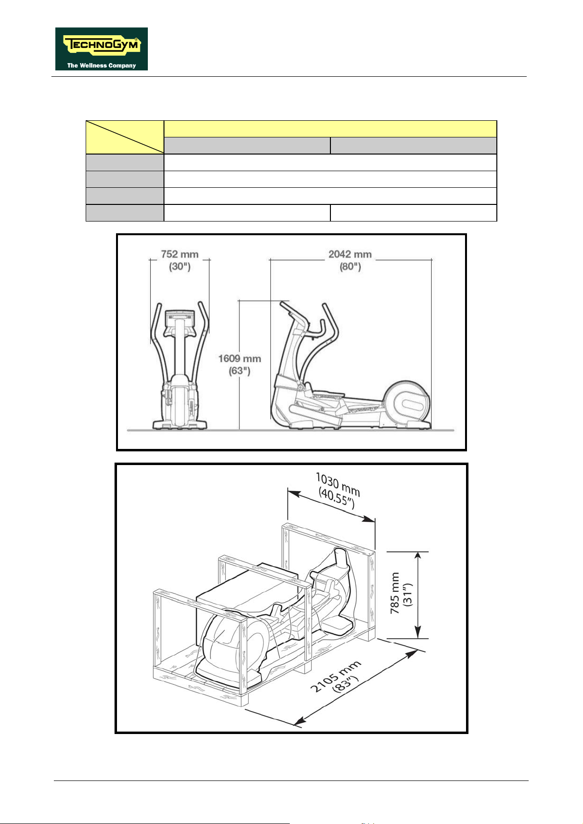
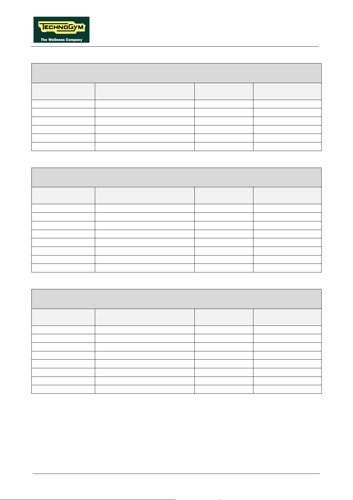
2.4. MECHANICAL CHARACTERISTICS
VERSION
500 – 700 - 700WTV 500SP – 700SP
Width
Length
Height
Weight
148 Kg - 326 lbs 150 Kg - 330 lbs
752 mm – 30”
2042mm – 80”
1609mm – 63”
Pagina 2.4
Page 17

SYNCHRO EXCITE Class & Trend: Service & maintenance manual - rev. 2.0
2.5. AMBIENT SPECIFICATIONS
Temperature
Humidity
Operating from 5° to 35° C
Storage from -10° to 70° C
Operating from 30% to 80% non-
condensing
Storage from 5% to 85% non-condensing
2.6. CONFORMITY TO REGULATIONS
The machine conforms to the following standards:
EMI
Safety
EN 957-9 classe SA (2003)
Directives
In addition:
• Electrical isolation class: Class I;
• Protection rating: IP21.
EUROPA USA
EN 55014-1 (2001)
EN 55014-2 (1998)
EN 61000-3-2 (2002)
EN 61000-3-3 (1997)
EN 60335-1 (1998)
EN 957-1 (2000)
73/23/CE
89/336/CE
98/37/CE
UL 1647
Page 2.5
Page 18

SYNCHRO EXCITE Class & Trend: Service & maintenance manual - rev. 2.0
2.7. WIRING DIAGRAMS
2.7.1. 500 MODEL (ARM BOARD)
2.7.1.1. Powered version (500)
CSAFE
DUAL
TGS
READER
C
N
1
BOARD
C
N
1
CBQ-13
CU-132
Patch
conn.
CBQ-32
C
N
7
C
N
2
KEYBOARD
C
N
8
ARM DIS PL AY BOARD
C
N
9
Patch
conn. 2
C
N
1
ELT- 05ELT-07
Patch
conn. 1
ELT-04ELT- 06
C
N
3
ELT- 16
DISPLAY
Patch
conn.
HFU
RECEIVER
NTC
VAC
Pagina 2.6
POWER
ENTRY
MODULE
ELT- 00
C
N
3
4
BRAKE
BOARD
C
N
C
N
1
C
N
2
ELT- 02
Patch
conn.
SPEED
SENSOR
BRAKE
Page 19

SYNCHRO EXCITE Class & Trend: Service & maintenance manual - rev. 2.0
2.7.1.2. Self-Powered version (500SP)
DUAL
TGS
READER
C
N
1
CU-132
Patch
conn.
CBQ-32
CSAFE
BOARD
CBQ-13
C
N
7
C
N
2
KEYBOARD
C
N
1
C
N
8
ARM DI SPLAY BOARD
C
N
9
Patch
conn. 2
C
N
1
ELT-05E LT-07
Patch
conn. 1
C
N
3
DISPLAY
ELT-16
HFU
RECEIVER
BATTERY
ALTERNATOR
BAT TER Y C H A RGER
INPUT
Patch
conn.
ELT-01
ELT-04ELT-06
C
N
4
C
BRAKE
N
3
BOARD
C
N
1
C
N
2
conn.
ELT-02
Patch
NTC
BRAKE
Page 2.7
Page 20

SYNCHRO EXCITE Class & Trend: Service & maintenance manual - rev. 2.0
2.7.2. 700 MODEL (ARM BOARD)
2.7.2.1. Powered version (700)
DUAL
TGS
READER
C
N
1
CU-132
Patch
conn.
CBQ-32
CSAFE
BOARD
CBQ-13
C
N
7
C
N
KEYBOARD
C
N
1
C
N
8
ARM DISPL AY BOARD
C
2
N
Patch
con n. 2
ELT-06
RECEIVER
9
HFU
ELT-16
C
N
conn. 1
3
C
N
1
ELT-05ELT-07
Patch
ELT-04
C
N
5
C
N
6
ELT-19
C
N
4
DISPLAY
Patch
conn.
Patch
conn. 6
ELT-31
NTC
LEF T
LEVER
RIGHT
LEVER
ELT-10 ELT-10
Patch
conn.
J
3
SENSOR
HAND
BOARD
2
J
1
J
4
J
Patch
conn.
2
J
CONNECTOR
BOARD
J
3
J
ELT-09
Patch
conn. 5
ELT-23
LEF T
HAND
SEN SOR
4
SENSOR
RIGHT
HAND
VAC
POWER
ENTRY
MODULE
ELT-0 0
C
BRAKE
BOARD
N
1
C
N
2
ELT-02
Patch
conn.
SPEED
SENSOR
BRAKE
C
N
3
C
N
4
Pagina 2.8
Page 21

SYNCHRO EXCITE Class & Trend: Service & maintenance manual - rev. 2.0
2.7.2.2. Self-Powered version (700SP)
DUAL
TGS
READER
C
CU-132
Patch
conn.
CBQ-32
BATTERY
HFU
RECEIVER
LEFT
LEVER
RIGHT
LEVER
ELT-1 0 ELT-10
CSAFE
BOARD
C
N
N
1
1
CBQ-13
C
N
8
ARM DI SPLAY BOARD
C
N
7
C
N
2
ELT-16
C
N
3
C
N
5
C
N
6
ELT-1 9
C
N
4
C
N
9
C
N
1
Patch
conn. 6
ELT-3 1
Patch
conn.
J
3
SENSOR
HAND
BOARD
2
J
J
1
J
4
KEYBOARD
Patch
conn.
2
J
CONNECTOR
BOARD
3
J
ELT-09
Patch
conn. 5
4
J
DISPLAY
ELT-23
ELT-01
Patch
con n . 2
ELT-0 6
C
N
C
N
3
4
BRAKE
BOARD
ELT-0 5ELT-07
Patch
conn. 1
ELT-0 4
C
N
Patch
conn.
1
C
N
2
ELT-0 2
NTC
BRAKE
LEFT
HAND
SENSOR
RIGHT
HAND
SENSOR
ALTERNATOR
BATTERY CHARGER
INPUT
Patch
conn.
Page 2.9
Page 22

SYNCHRO EXCITE Class & Trend: Service & maintenance manual - rev. 2.0
2.7.3. 700 WELLNESS TV MODEL – DIGITAL TV
2.7.3.1. Powerded version (700WTV)
CONNECTORS
PANEL
DUAL TGS
READER
1
N
C
CU132
Patch
Conn.
INVERTER
DISPLAY
Antenna
inlet
ELT-32
iPOD DOCKING
STATION
C-SAFE
CU167
CU166
tuner
DIGITAL TV
CU124
CU146
1
N
C
CBQ-32
LCD
C
8
N
N
C
F
S
1
N
C
CU240
5
J
3
C
1
N
N
C
3
2
N
C
BOARD
ASSEMBLY
7
J
CU160
N
C
1
3
2
N
C
5
CPU BOARD
N
C
A
8
2
CU82
Patch
conn.
HEADPHONE
JACK
TOUCH
SCREEN
ELT-07
L R
V
CONNECTORS BOARD
CU164
9
1
J
J
0
1
J
J
8
CU158
2
N
C
2
N
C
0
3
CU169
N
C
Patch
conn. 3
LEFT
LEVER
ELT-10
3
J
Pach
Conn.
HAND
SENS O R
BOARD
0
2
C
1
2
N
1
N
C
9
2
N
C
6
C
7
2
N
ELT-16
LEFT
RIGHT
HFU
RECEIVER
Pach
Conn. 6
ELT-19
ELT-31
CONNECTORS
2
J
1
J
4
J
2
J
BOARD
RIGHT
LEVER
ELT-10
Pach
Conn.
3
J
4
J
ELT-09
Pach
Conn. 5
ELT-05
ELT-23
LEFT
HAND
SENSOR
RIGHT
HAND
SENSO R
Pagina 2.10
VAC
POWER
ENTRY
MODULE
CU128
Patch
Conn. 2
Patch
Conn. 1
ELT-06 ELT-04
3
N
C
BRAKE
4
N
C
BOARD
Patch
Conn.
1
N
C
C
2
N
ELT-02
Patch
Conn.
NTC
SPEE D
SEN SO R
BRAKE
Page 23

SYNCHRO EXCITE Class & Trend: Service & maintenance manual - rev. 2.0
2.8. WIRING
The connectors indicated in the following pages, refer to 700 model’s LED Boards, unless
otherwise indicated.
The colour of the cables can be changed, refer in particular to the Pin Out.
2.8.1. CBQ CABLES
CBQ-13: CSafe board cable
(Display Board – CSafe Board)
Display Board
CN8
1 Digital #1 Flat cable 1
… … … …
14 Digital #14 Flat cable 14
Display Board:CN7
CPU Board:CN8
1 +12 Vdc power supply Rosso 8
3 Rx Marrone 1
5 Tx Blu 2
9 Gnd Nero 6
Signal Colour
CBQ-32: TGS Cable
(Display/CPU Board – Patch connector)
Signal Colour Patch conn.
CSafe Board;
CN1
2.8.2. CB CABLES
Scheda connettori
CN1
1 Color Red 1
2 left audio IN White 2
3 Gnd
4 right audio IN Red 4
5 Gnd Braid 5
6 video IN Yellow 6
7 Gnd
8 Switching White 8
CB-9: DVD video input cable
(Connectors Board –Input AUX Board)
Segnale Coloure
Braid
Braid
Scheda input
J2
3
7
Page 2.11
Page 24

SYNCHRO EXCITE Class & Trend: Service & maintenance manual - rev. 2.0
2.8.3. CU CABLES
CU132: TGS Cable
(Patch conn. – Dual TGS reader)
Patch conn. Signal Colour
1
8
7
3
+12 Vdc power supply
Rx
Tx
Gnd
CU158: AUX signals cable
(CPU board –Digital TV board)
CPU board
CN22
1
2
3
4
5
6
GND video signal
Video signal
GND Left audio signal
Left audio signal
Right audio signal
GND right audio signal
Signal Colour
CU160: CSafe – iPod – Video signals cable
(CPU board – Digital TV board)
CPU board
CN25
1
2
3
6
7
8
9
10
11
12
13
14
Power supply +8 Vdc
Power supply +8 Vdc
Power supply +8 Vdc
RX – TX
TX – RX
CTS
Power supply +5 Vdc
Power supply +5 Vdc
GND DTV board sensing
GND “Play” sensing
GND
GND
Signal Colour
Dual TGS reader
CN1
Black 1
Green 2
Black
Black
3
8
Digital TV board
J8
Black
White 6
Black
White 2
White 4
Black
Digital TV board
Black
Black
Black
Black
Black
Black
Black
Black
Black
Black
Black
Black
7
3
5
J7
1
2
3
7
6
8
9
10
11
12
13
14
Pagina 2.12
Page 25

SYNCHRO EXCITE Class & Trend: Service & maintenance manual - rev. 2.0
CU164: Audio/Video signal cable
(Digital TV board – AUX input board)
Digital TV board
J10
1 GND video Black 1
2 Signal video Black 2
3 GND audio L Black 3
4 Signal audio L Black 4
5 Signal audio R Black 5
6 GND audio R Black 6
n.c. Black 7
Signal Colour
CU166: CSafe – iPod – Video signals cable
(Digital TV board – AUX input board)
Digital TV board
J9
1 Power supply +8 Vdc Black 1
2 Power supply +8 Vdc Black 2
3 Power supply +8 Vdc Black 3
6 RX – TX Black 7
7 TX – RX Black 6
8 CTS Black 8
9 Power supply +5 Vdc Black 9
10 Power supply +5 Vdc Black 10
11 GND DTV board sensing Black 11
12 GND “Play” sensing Black 12
13 GND Black 13
14 GND Black 14
15 n.c. Black -
Signal Colour
CU167: iPod signals cable
(AUX input board – Docking Station)
AUX input cable
1 +V bus USB Black 14
2 GND bus USB Black 13
3 TX - RX Black 11
4 RX – TX Black 12
5 CTS Black 10
6 +5Vdc Black 9
7 GND Black 8
8 GND Black 7
9 GND video signal Black 6
10 Video signal Black 5
11 GND Lef audio signal Black 4
12 Left audio signal Black 3
13 Right audio signal Black 2
14 GND Right audio signal Black 1
Signal Colour
AUX input board
AUX input board
Docking Station
Page 2.13
Page 26

Patch connn.
CPU board
SYNCHRO EXCITE Class & Trend: Service & maintenance manual - rev. 2.0
CU169: Display power supply cable
(CPU board – Digital TV board – Patch conn.)
Signal Colour
1 GND
2 GND 12Vdc Black 2 -
3 GND 5Vdc Black - 2
4 sensing GND 5Vdc Black - 4
5 n.c. - - -
6 +12Vdc
7 +5 Vdc
8 sensing + 5Vdc
Yellow/Green
Red
Red
Red
CPU board
CN20
1 -
6 -
- 1
- 3
Digital TV board
J1
CU240: LCD inverter power supply cable
(CPU Board – Inverter LCD)
CN5
1
5
2 GND Black 3
4 GND Black 4
Input voltage + 12 Vdc
Input voltage + 12 Vdc
Signal Colour
Black
Black
Power system return:
3
7 n.c. Black 6
6 Lamp control Black 7
5Vdc = ON
0Vdc = OFF
Black
5
LCD Inverter
CN1
1
2
2.8.4. ELT CABLES
ELT-00: High voltage cable
(Power entry module – Brake board)
Power entry module Signal Colour
F Line White 1
N Neutral Black 3
T Earth Green 5
Brake board
CN4
Pagina 2.14
Page 27

SYNCHRO EXCITE Class & Trend: Service & maintenance manual - rev. 2.0
ELT-01: Alternator cable
(Brake board – Alternator – Battery – Inlet for battery charging)
Brake board
CN3
1 V+ voltage from
alternator
2 V- voltage from
alternator
3 RPM signal White Faston
4 V+ voltage from
battery charger
5 V- voltage from
battery charger
6 Battery V+ Red - Faston 7 Battery V- Black - Faston -
Signal Colour Alternator Battery
Red Faston -
Black Faston -
Red - soldered to internal
Black - soldered to external
ELT-02: Brake supply cable
(Brake board – Brake – Speed sensor – NTC)
Brake board
CN2
1 Brake supply + Brown Faston - 2 Brake supply - Blue Faston - -
3 SPM Grey 4 SPM Reference Black - eyelet -
5 NTC + White - - 2
6 NTC - Brown - - 1
Signal Colour
Brake
ELT-04: Power supply cable between upper and lower assemblies
(Brake board - Patch connector 1)
Brake board
CN1
2 Gnd Blue 2
3 Gnd Red 3
4 - sensing +5 Vdc digital Black 4
6 +12 Vdc White 6
7 +5 Vdc Green 7
8 +sensing +5 Vdc digital Orange 8
Signal Colour
Battery charging
inlet
contact
contact
Speed sensor NTC
Faston connected
to brown cable
Patch connector
1
-
Page 2.15
Page 28
SYNCHRO EXCITE Class & Trend: Service & maintenance manual - rev. 2.0
ELT-05: Power supply cable between upper and lower assemblies
(Patch connector 1 - Display Board)
Patch connector
1
2 Gnd Red 2
3 Gnd White 3
4 - sensing +5 Vdc digital Green 4
6 +12 Vdc Black 6
7 +5 Vdc Blue 7
8 +sensing +5 Vdc digital Orange 8
Signal Colour
Display Board
ELT-06: Serial communication cable between upper and lower assemblies
(Brake board - Patch connector 2)
Brake board
CN4
1 Digital Gnd Orange-White 1
2 Digital Gnd Orange 2
3 NC Green-White 3
4 Download Blue 4
5 Reset Blue-White 5
6 NC Green 6
7 485 Tx/Rx + Brown-White 7
8 485 Tx/Rx - Brown 8
Signal Colour Patch connector 2
ELT-07: Serial communication cable between upper and lower assemblies
(Patch connector 2 - Display Board)
Patch connector 2 Signal Colour
1 Digital Gnd Orange-White 1
2 Digital Gnd Orange 2
3 NC Green-White 3
4 Download Blue 4
5 Reset Blue-White 5
6 NC Green 6
7 485 Tx/Rx + Brown-White 7
8 485 Tx/Rx - Brown 8
Display Board
CN1
CN9
Pagina 2.16
Page 29

SYNCHRO EXCITE Class & Trend: Service & maintenance manual - rev. 2.0
ELT-09: Handlebar sensor cable
(Connector board - Patch connector 5)
Connector board
J3
1 Gnd Braid 1
2 Sensor signal reference White 2
3 Left sensor signal Black 3
4 Gnd Braid 4
5 Sensor signal reference Green 5
6 Right sensor signal Red 6
Signal Colour Patch connector 5
ELT-10: Lever cable
(Patch connector – Lever)
Patch connector Signal Colour
1 Sensor signal Clear Faston 2 Gnd Braid - 3 Lever button signal Green - 2
4 Sensor signal reference Black Faston 5 Reference Brown - 4
6 + 5Vdc Power supply White - 1
Sensor Button
Lever
ELT-16: HFU Receiver cable
(Display Board – HFU Receiver)
Display Board
CN3
1 +5 Vdc power supply White 2
7 Pulse (beat to beat) Black 4
8 Gnd Green 1
Signal Colour HFU Receiver
ELT-19: Hand sensor board cable - Lever buttons
(Display Board - Patch connector 6)
Display Board
CN4 CN5 CN6
1 - - + 5Vdc Power supply Red 8
2 - - NA Green 7
3 - - NA Orange 1
5 - - Out pulse Blue 3
6 - - Reference Black 2
- 1 - + 5Vdc Power supply White 12
- 2 - Left lever button (-). Green 11
- 4 - Reference Brown 10
- - 1 + 5Vdc Power supply White 6
- - 2 Right lever button (+). Green 5
- - 4 Reference Brown 4
Signal Colour
Patch connector
6
Page 2.17
Page 30

SYNCHRO EXCITE Class & Trend: Service & maintenance manual - rev. 2.0
ELT-23: Handlebar sensor cable
(Patch connector 5 – Sensors)
Sensors Patch
connector
Signal Colour
1 Gnd Braid - - - 2 Sensor signal reference Black - - down down
3 Left sensor signal White - - up up
4 Gnd Braid - - - 5 Sensor signal reference Black down down - 6 Right sensor signal White up up - -
rh 1 rh 2 lh 1 lh 2
ELT-31: Hand sensor board cable - Lever buttons
(Patch conn. 6 - Hand sensor board - Lever connectors - Connector Board)
Patch
connector
6
8 + 5Vdc Power supply Red 4 - - - 7 NA Green 1 - - - 1 NA Orange 2 - - - 3 Out pulse Blue 5 - - - -
2 Reference Black 3 - - - 12 + 5Vdc Power supply White - - 6 - 11 Left lever button signal
(–)
10 Reference Green - - 5 - -
- Gnd Braid - - 2 1 -
- Reference Black - - 4 2 -
- Left sensor signal Clear - - 1 3 6 + 5Vdc Power supply White - 6 - - 5 Right lever button signal
(+)
4 Reference Green - 5 - - -
- Gnd Braid - 2 - - 1
- Reference Black - 4 - - 2
- Right sensor signal White - 1 - - 3
Signal Colour
Brown - - 3 - -
Brown -
Hand Sensor
Board
J3
Lever
connector
RH LH J2 J4
3
Connector
board
- - -
Pagina 2.18
Page 31

SYNCHRO EXCITE Class & Trend: Service & maintenance manual - rev. 2.0
3. PRINCIPLES OF OPERATION
3.1. BLOCK DIAGRAM
The machine block diagram is illustrated in the figure below:
C-SAFE
BOARD
DUAL TGS
READER
POWERED VERSION
LED DISPL AY
KEYBOARD
iPOD DOCKI NG
STATION
TOUCH SCREEN
DISPLAY BOARD
WTV DISPLAY
CONNECTORS BOARD
DIGITAL TV
BOARD
ASSEMBLY
CORDLESS VERSION
L RC-SAFE V
CONNECTORS
BOARD
SENSORS
RIGHT
LEVER
RIGHT
TOUCH
tuner
LEFT
LEVER
HAND
SENSOR
BOARD
LEFT
TOUCH
SENSORS
DISPLAY
VAC
SPEED
SENSOR
NTC
POWER
ENTRY
MODULE
BRAKE
BRAKE
BOARD
BRAKE
BOARD
BATTERY
NTC
BRAKE
BATTERY
CHARGER
INPUT
Exte rnal
power supply
Page 3.1
Page 32

SYNCHRO EXCITE Class & Trend: Service & maintenance manual - rev. 2.0
3.1.1. LED ARM DISPLAY BOARDS (500 AND 500SP)
The display contains only one board which comprises the CPU, an ARM microprocessor, its logic
circuits and a FLASH EPROM containing the operating program for the machine moreover, acts as
the interconnection hub for all the components of the display and serves as the point of connection
with the brake Board.
The main functions of the board are:
¾ Manages and process signals from:
• Keyboard;
• HR receiver;
• CSafe Board;
• TGS reader (if present).
¾ distributes the voltages received from the Brake Board to the display;
¾ exchanges, via the RS-485 serial link to the Brake Board, the commands for controlling the brake;
¾ controls the LEDs and the 7-segment displays which provide feedback about the exercise session.
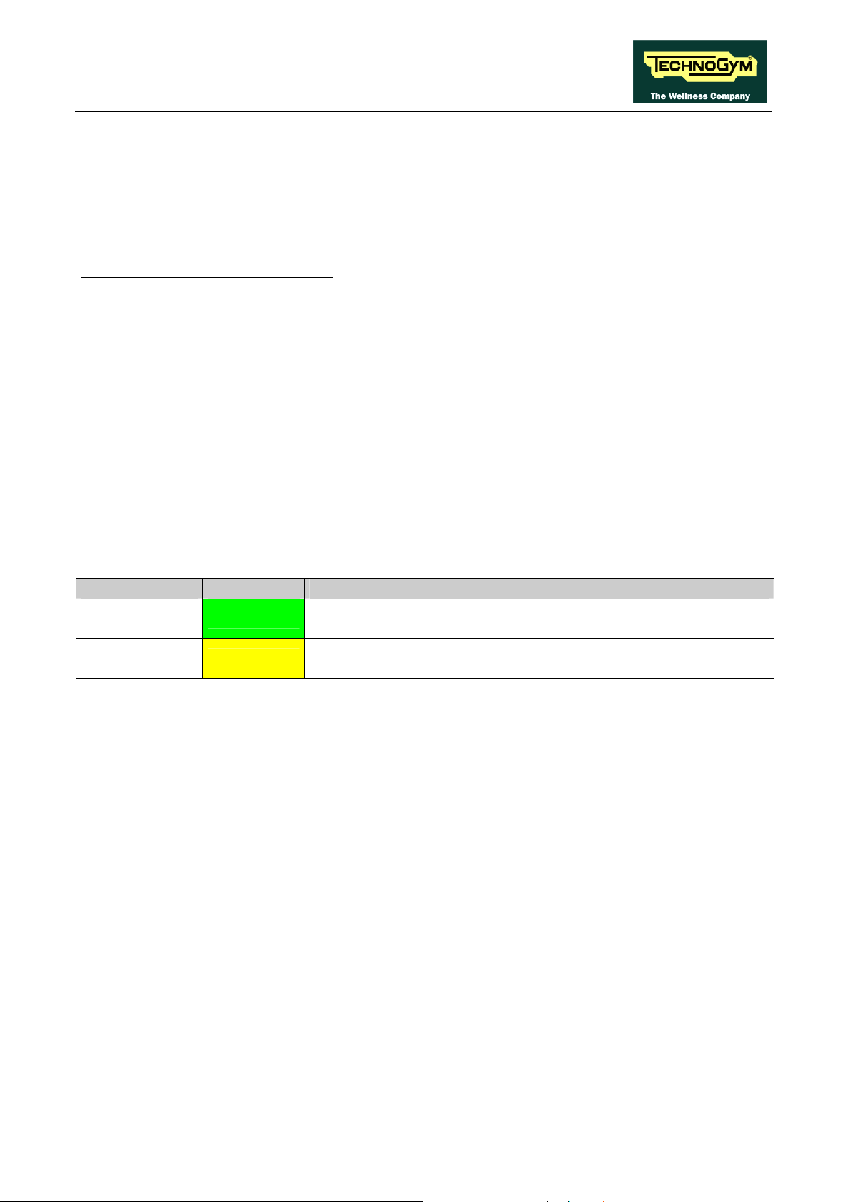
The board includes the following indicator LEDs:
LED name Colour Description
LED1 green
LED2 yellow
if ON the +12 Vdc power supply from the Brake Board correctly
reaches the board.
if ON the +5 Vdc power supply from the Brake Board correctly
reaches the board.
Pagina 3.2
Page 33
SYNCHRO EXCITE Class & Trend: Service & maintenance manual - rev. 2.0
3.1.2. LED ARM DISPLAY BOARDS (700 AND 700SP)
The display contains only one board which comprises the CPU, an ARM microprocessor, its logic
circuits and a FLASH EPROM containing the operating program for the machine moreover, acts as
the interconnection hub for all the components of the display and serves as the point of connection
with the Brake Board.
The main functions of the board are:
¾ Manages and process signals from:
Keyboard;
HS/HR receiver;
Touch sensor
CSafe Board;
TGS reader (if present).
¾ distributes the voltages received from the Brake Board to the display;
¾ exchanges, via the RS-485 serial link to the Brake Board, the commands for controlling the brake;
¾ controls the LEDs and the 7-segment displays which provide feedback about the exercise session.
The board includes the following indicator LEDs:
LED name Colour Description
LED1 green
LED2 yellow
if ON the +12 Vdc power supply from the Brake Board correctly
reaches the board.
if ON the +5 Vdc power supply from the Brake Board correctly
reaches the board.
Page 3.3
Page 34

SYNCHRO EXCITE Class & Trend: Service & maintenance manual - rev. 2.0
3.1.3. WELLNESS TV DISPLAY BOARDS –DIGITAL TV (700WTV)
3.1.3.1. CPU board
The board is called “Unified Board”, it is the circuit board which incorporates the CPU, its control
logic, the FLASH EPROM containing the operating program of the machine.
It is the circuit board which acts as the interconnection hub for all the components of the display
and serves as the point of connection with the digital TV Board and the Brake Board.
The main functions of the board are:
¾ Manages and process the signal from:
LCD;
Inverter for LCD;
Touch screen;
Headphone jack;
AUX input Board;
HS/HR receiver;
Touch sensors;
TGS reader (if present);
iPod docking station (if present).
¾ Distributes the voltages received from the Brake Board to the display;
¾ Exchanges, via the RS-485 serial link to the Brake Board, the commands for controlling the brake;
¾ Manages the display of images on the LCD.
The board includes the following indicator LED:
LED name Colour Description
D41 green
and a faston:
Nome Descrizione
if ON the +12 Vdc supply from the Brake Board correctly
reaches the CPU board.
J2
denotes a ground node on the circuit
board.
3.1.3.2. Digital TV board
It’s the circuit board which contains the decoder and all the components needed to receive and
manage the aerial antenna signal.
Directly to this board it is connected the antenna cable. Here it’s signal is amplified, divided
between the video and audio signal, codified by the decoder and managed by the tuner which
allows to tune the TV and radio channels.
Due to its positioning on the rear display support, just over the AUX input board, it is also used as a
“bridge” for the signals between AUX input board and iPod docking station, and CPU board.
Pagina 3.4
Page 35

SYNCHRO EXCITE Class & Trend: Service & maintenance manual - rev. 2.0
3.1.3.3. LCD Inverter
This device powers the LCD Display lamps. It receives DC power supplies (12 Vdc supply and 3.3
Vdc enable signal) from the CPU Board, and generates the AC voltage (380 Vac) needed to power
the LCD.
3.1.3.4. Touch screen interface board
This is the board that controls the 4-wire resistive Touch Screen and interfaces the Touch Screen to
the CPU Board.
3.1.3.5. AUX input board
It is the circuit Board which allows audio and video external sources to be displayed on the LCD
base band. The board m
anages also the functions of the CSafe Board, detailed in the following
pages, and provides 3 RC connectors and the RJ45 connector for the CSafe communication.
3.1.3.6. iPod docking station
It is the device that allows to plug & store iPod m
odels, in a safe docking station and to control it
from the ACTIVE Wellness TV interface.
With the docking station, developed for the full compatibility with iPod, it is possible to power,
recharge and fully control it from the touch screen of the machine.
In the following table, all the compatible iPod models:
iPod 5st gen.
iPod Classic
iPod mini
iPod Nano
iPod Touch
iPhone
3.1.3.7. Headphone jack
The machine display has one jack for connecting headphones. The jack is connected on a stereo
output of the CPU Board.
Page 3.5
Page 36

SYNCHRO EXCITE Class & Trend: Service & maintenance manual - rev. 2.0
3.1.4. CSAFE BOARD
This board makes available a communication port, on 1 externally accessible connector, which can
be used for interfacing compatible CSafe devices such as the CardioTheater readers. This connector
is situated on the back of the display.
On Wellness TV models these functions are carried out by the AUX Input Board.
These connectors can also be interfaced, using a special cable, to an external PC for programming
the FLASH EEPROM.
3.1.5. DUAL TGS READER
It’s the device which allows the machine to interact with the Wellness System.
This board enables the machine to read the user's TGS key for performing workouts programmed
with the propers SW of the Wellness System.
With Dual TGS reader it is possible to use both the Botom and the Mifare TGS keys.
3.1.6. CARDIO RECEIVER
This board manages the signal received from the telemetric transmitter used by the person
exercising. It receives the power supply signal from the display board and outputs a negative logic
pulse for every heart beat that is detected: the signal level is normally 5 Vdc, with a pulse at 0 Vdc
(having a width of approximately 30 msec) at each heart beat.
The receiver reception area is approximately a circle with a 1 m radius. If there is electromagnetic
noise (produced by high voltage lines, radio transmitters, monitors, motors etc.) within this area, the
receiver becomes saturated and no longer receives any signal.
Pagina 3.6
Page 37
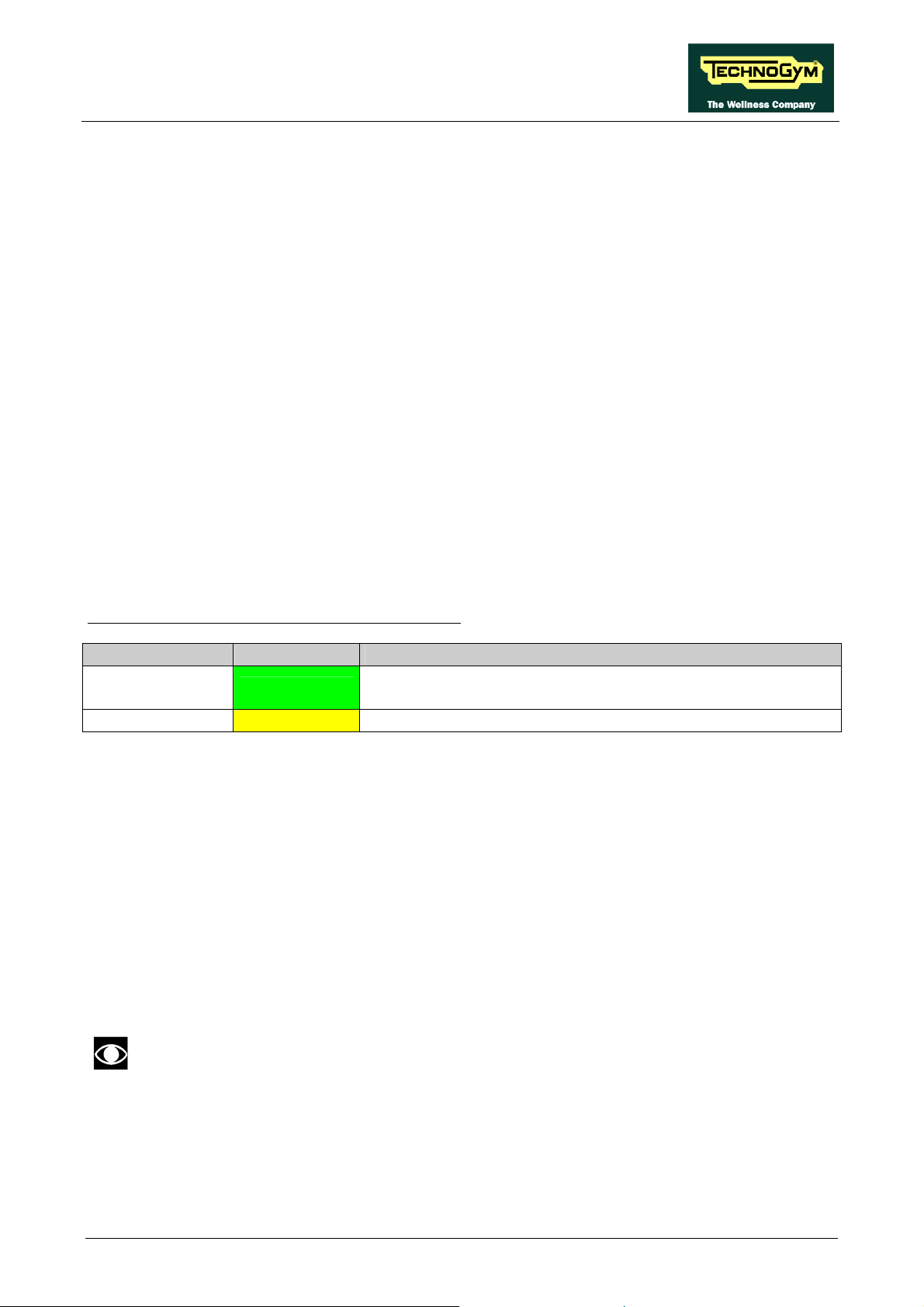
SYNCHRO EXCITE Class & Trend: Service & maintenance manual - rev. 2.0
3.1.7. BRAKE BOARD
There are 2 versions of the Brake Board, one which is used on the mains powered version and the
other on the self-powered version. In either case, the Brake Board consists of:
¾ Power supply section which generates the low voltages used by the machine: +5 Vdc and
+12 Vdc. Depending on the machine version, these voltages will be generated either from the
110 VAC or 220 VAC mains supply, or from the alternator-battery.
¾ Section for RS-485 serial communications with the Display Board for:
commands determining the resistance that is required of the brake;
brake error messages;
commands for modifying the circuit board configuration parameters;
commands for viewing the errors logged by the circuit board.
¾ Section which generates the current for the brake winding: varying the current produces a
proportional variation in the resistance of the brake. The excitation current supplied to the
brake is a function of the effort level selected on the display and the RPM value measured by
the speed sensor (angular velocity of the brake disk) and is determined by the values stored
in the braking table.
The board includes the following indicator LEDs:
LED name Colour Description
LED1 green
LED2 yellow
if ON the board is supplying the brake winding.
if BLINKING the Brake Board is in an error condition.
if ON there is the +5 Vdc supply from the circuit Board.
3.1.8. BRAKE
This is an eddy current brake, consisting of a flywheel mass and a flat copper disk that rotates in the
air gap of a winding. Variations in the winding current produce a change in the resulting field,
which consequently varies the eddy currents induced within the copper disk and hence its resistance
to movement.
The winding has a resistance of approximately 3.5 (Ohm).
A klixon thermal cut-out, installed directly on the winding, interrupts the circuit whenever it detects
a temperature exceeding 140°C.
3.1.9. SPEED SENSOR
Only for 500, 700 and 700WTV versions.
This consists of a magnetic induction sensor which detects the heads of the brake disk fixing screws.
On the self-powered machine, the speed sensor is directly built-in on the alternator (see paragraph
3.1.11. “Alternator”).
Page 3.7
Page 38

SYNCHRO EXCITE Class & Trend: Service & maintenance manual - rev. 2.0
3.1.10. POWER ENTRY MODULE
This is a module consisting of:
• power inlet socket;
• power outlet socket;
• fuse-holder for protecting line voltage and neutral with two 3.15A fast-blow fuses.
It is situated on the side of the rear platform.
WARNING: The power entry module has a maximum current rating of 10 A. This places an
upper limit on the number of machines that can be connected together. Therefore, do not
connect more than 6 New Bike Excite machines with a 220 VAC mains supply, or 3 machines
with a 110 VAC mains supply. If other types of machines are connected together, the
maximum number is determined by their current draw.
3.1.11. ALTERNATOR
Only for 500SP and 700SP versions.
The alternator consists of a stator winding whose rotor is put into rotation by the movement of the
pedals, generating the voltage necessary for the machine’s operation.
Depending on the rate of pedaling and the resulting speed of rotation, it generates an alternating
voltage which ranges from approximately 15-17 VAC at about 30-35 RPM to over 40 VAC for
higher pedaling speeds.
The alternator has a built-in speed sensor which provides to the Brake Board the speed signal.
3.1.12. BATTERY
Only for 500SP and 700SP versions.
This is a 12 V – 4.5 AH battery which, in the self-powered version, supplies the machine whenever
the alternator is unable to produce a sufficient voltage for powering the machine, and for at least 30
seconds after the user has stopped pedaling to allow data to be saved in memory.
The battery can be recharged in 2 ways:
• during the exercise, through the Brake Board;
• in the standby condition, from an external power supply included with the machine, which is
able to fully recharge the battery in 8 hours.
Do not use the machine during recharging with the external power supply.
Pagina 3.8
Page 39

SYNCHRO EXCITE Class & Trend: Service & maintenance manual - rev. 2.0
3.1.13. EXTERNAL POWER SUPPLY INPUT
Only for 500SP and 700SP versions.
This is a socket for plugging in the external power supply that comes with the machine, which can
be used to recharge the battery. It is situated on the side of the front platform.
Page 3.9
Page 40
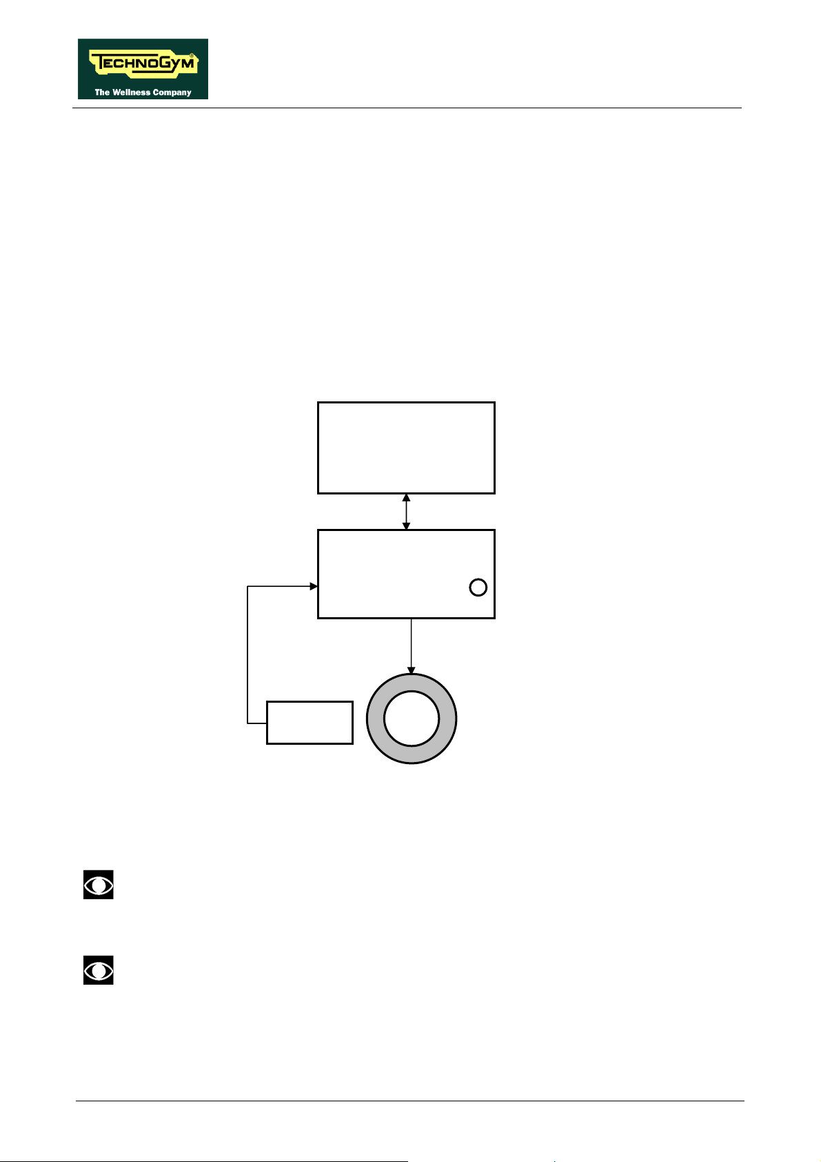
SYNCHRO EXCITE Class & Trend: Service & maintenance manual - rev. 2.0
3.2. BRAKE CONTROL
3.2.1. MECHANICS
The motion of the pedals imparts a rotation to the primary shaft via the belts and pulley system.
The primary shaft is connected to the secondary shaft and so to the brake, by means of a belt. The
speed sensor (only on mains operated models) attached to the frame detects the heads of the screws
which secure the disk to the flywheel, and generates a signal proportional to the speed. On self
powered machine, the speed value is detected measuring a phase of the alternator.
3.2.2. CONTROLS
The control block diagram is as follows:
Display Board
Pulses
Brake board
3-4/CN2
Speed
sensor
To obtain a given exercise effort level, the Display Board sends the required value of “electrical”
resistance to the Brake Board via the RS-485 serial link. Based on the commands received and the
feedback signal from the speed sensor, the Brake Board will then apply the appropriate excitation
current to the brake winding and generate an electromagnetic field.
CN9
RS-485
CN3
1-2/CN2
Excitation Current
Brake
Green LED
The value of the current applied is based on the value of the brake table memorized into the
Brake Board.
When the brake interface board receives the signal to generate resistance, the green LED
illuminates.
Pagina 3.10
Page 41

SYNCHRO EXCITE Class & Trend: Service & maintenance manual - rev. 2.0
The electromagnetic field produced by the winding and the rotation of the disk will induce eddy
currents in the disk itself, giving rise to a force that tends to brake its motion. This generates the
exercise resistance.
A higher brake excitation signal will produce a correspondingly higher exercise resistance. In
addition, for a given value of brake excitation, a higher speed of disk rotation will produce a
correspondingly higher exercise resistance.
Due to the eddy currents, energy is dissipated on the brake disk in the form of heat.
The Brake Board effects an open loop control of the brake, with no provision for regulating the
value of resistance produced but only uses the brake table memorized into the Brake Board.
The precision of the braking system has a tolerance of ±10%.
During the movement, the speed sensor detects the heads of the brake disk fixing screws, and
produces a speed feedback signal that is sent to the Brake Board, on the mains operated machines.
On the self powered machines, the speed signal comes directly from the measure of an alternator
phase.
If the Brake Board does not receive a speed signal, which indicates that an exercise session is in
progress, the machine will not produce any resistance.
During the movement, the Brake Board monitors for possible malfunctions. The errors which can
occur are:
Error Code Description
1
2
8
OVERHEATING: this condition occurs when the temperature detected by
the sensor on the circuit board exceeds 90°C.
OVERCURRENT: this condition occurs when the Brake Board detects an
excessive amount of current being sent to the winding.
OVERVOLTAGE: this condition occurs when the +12 Vdc voltage goes
above 13.7 Vdc (only on the 500, 700 and 700WTV models).
SOLENOID OVERHEATING: this condition occurs when the NTC,
16
connected in series with the solenoid, detects a temperature higher than 140°C
and opens the circuit.
32
128
EPROM: SW error on the Brake Board (braking table).
REFERENCE VOLTAGE FAULT: this error condition occurs when the
calibration parameter stored in the Brake Board is incorrect.
In the case of error 128, the machine remains fully functional, but the braking resistance produced
will not correspond to the value entered on the display. In all other cases, the Brake Board
interrupts the supply of current to the brake, the green LED changes from being steadily on to
blinking and sends an error message to the Display Board which displays the “THE EQUIPMENT
IS BLOCKED (COM)” message.
Page 3.11
Page 42

SYNCHRO EXCITE Class & Trend: Service & maintenance manual - rev. 2.0
3.2.3. THE SIGNALS INVOLVED
The machine uses the following control signals:
• RS-485 Signal
This is a digital signal exchanged between the Brake Board and the Display Board. There is no
provision for monitoring its state.
• Excitation current
This is the current generated by the Brake Board (pins 1-2 of connector CN2) which supplies
the brake winding. The current supplied is a function of the adjustment algorithm.
• Pulses
This is the signal produced by the speed sensor, and has the waveform shown in the figure
below:
Figure 3.2-1
The signal enters the Brake Board (pins 3-4 on connector CN2), where it is used to determine
the speed value (RPM)that is sent to the Display Board via the RS-485 serial link.
This signal can also be measured qualitatively using a multimeter. The voltage measured
across the sensor terminals should be 0 Vdc when the machine is stopped, and should increase
to a few hundred mV during pedal movement: the higher the speed, the higher the measured
voltage.
Pagina 3.12
Page 43

SYNCHRO EXCITE Class & Trend: Service & maintenance manual - rev. 2.0
4. ACCESSORIES
4.1. CARDIO THEATER CONNECTION
The machine can be connected to the CardioTheater by means of the RJ45 connector on the CSafe
board. The CardioTheater unit must be provided with a power cable having the following pin-out:
RJ45 Connector Signal
5 +5 Vdc
7 Ground
WARNING: for the numbering of the pins, on RJ45 connector, please refer to the diagram
below:
Page 4.1
Page 44

SYNCHRO EXCITE Class & Trend: Service & maintenance manual - rev. 2.0
4.2. PC LINK FOR PROGRAMMING
The machine can be connected to a PC for programming by means of the RJ45 connector on the
CSafe board.
WARNING: for the numbering of the pins, on RJ45 connector, please refer to the diagram
below:
When programming the machine sometimes it is necessary to fit plug into the free RJ-45 port
on the back of the display, to avoid any type of interference during the operation.
The wiring diagram of the RJ-45 plug is as follows:
Programming cable and plug can be ordered using the code H0002534AB.
Pagina 4.2
Page 45

SYNCHRO EXCITE Class & Trend: Service & maintenance manual - rev. 2.0
4.3. CABLE FOR EXCHANGING TV CHANNEL TUNING DATA
BETWEEN TWO MACHINES
The link for transferring the TV channel tuning data from one machine to the other is effected via a
special cable, which plugs into the RJ45 connectors of the CSafe boards.
The cable to use (code 0WC00644AA) must be wired as follows:
Cable CSafe Periferic
CSafe Board;
RJ45
3 Tx White 4
4 Rx Brown 3
7 Digital Ground Green 7
8 Ground Shield Yellow 8
Signal Colour CSafe Board;
RJ45
WARNING: for the numbering of the pins, on RJ45 connector, please refer to the diagram
below:
Page 4.3
Page 46
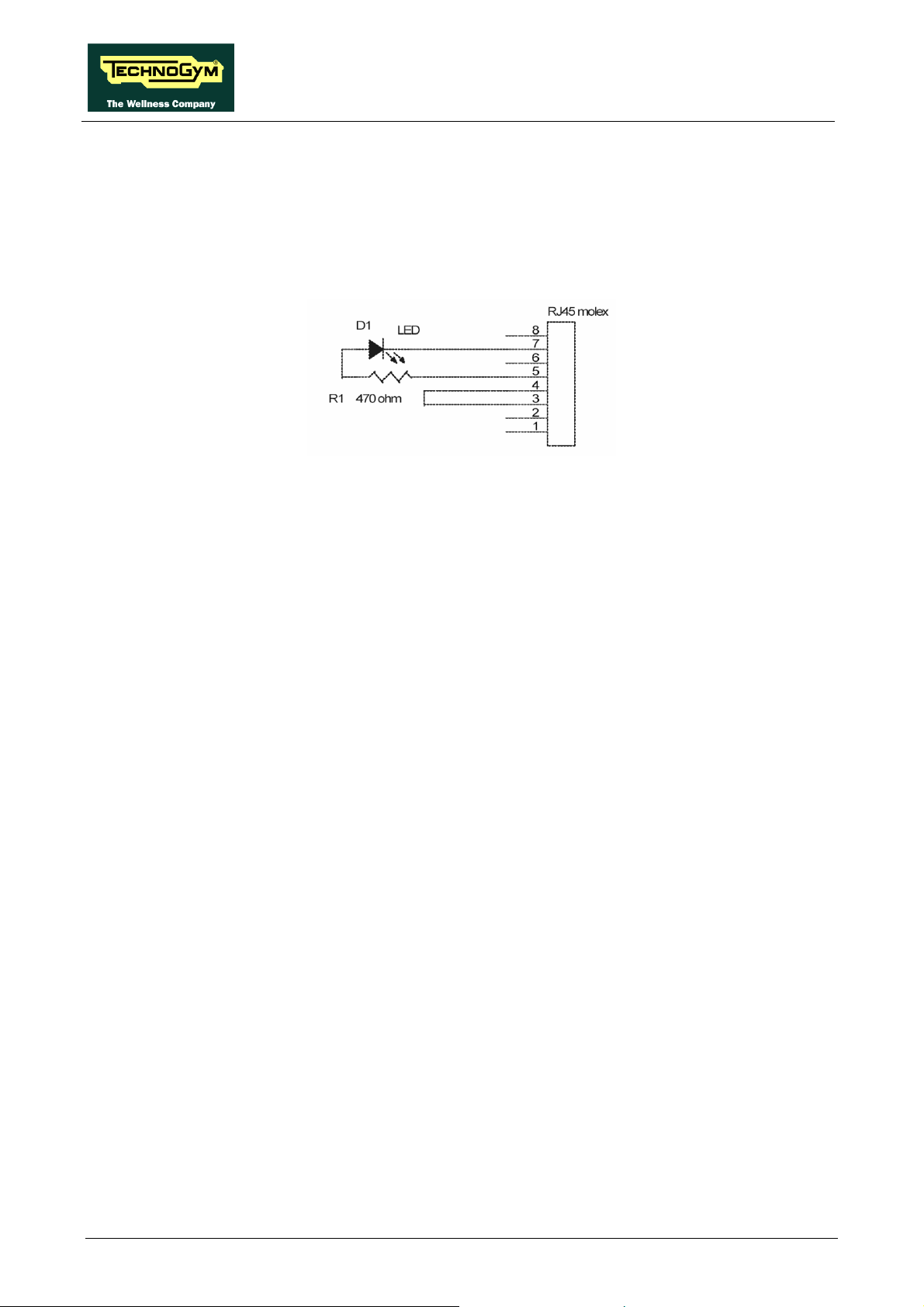
SYNCHRO EXCITE Class & Trend: Service & maintenance manual - rev. 2.0
4.4. MONITOR PLUG FOR CSAFE PORT
When the plug code 0WC00639AA is fitted into any one of the CSafe ports on the machine, the
corresponding LED should illuminate to indicate the presence of the 5 Vdc supply on the port.
During the CSafe port test function, the plug connects the transmit channel directly to the receive
channel, thereby producing a positive test outcome if the port is functioning correctly.
Pagina 4.4
Page 47

SYNCHRO EXCITE Class & Trend: Service & maintenance manual - rev. 2.0
4.5. WELLNESS TV UPGRADE KIT
There are upgrade kits available for converting Excite machines from the version with traditional LED
Display to the Wellness TV Display version with ACTIVE TV interface and integrated digital TV
decoder. The kit also includes all the cables and connectors required for the input of the antenna
signal.
The table below gives the codes of the kits, to be chosen according to the TV standard used in the
installation country.
WELLNESS TV
UPGRADE KIT
SYNCHRO 700 DVB-T A0000404-D
SYNCHRO 700 ATSC A0000404-A
SYNCHRO 700 ISDB-T A0000404-I
In the following table you can find the list of the analogyc and digital TV standard of the different
countries.
DIGITAL
COUNTRY
ALBANIA
ANGOLA
AUSTRALIA
AUSTRIA
AZERBAIJAN
BAHAMAS
BAHRAIN
BELGIUM
BERMUDA
BRAZIL
BULGARY
CANADA
COLOMBIA
CYPRUS
CZECH REPUBLIC
DENMARK
EGYPT
FAROE ISLANDS
FINLAND
FRANCE
GERMANY
GHANA
GREECE
HONG KONG
HUNGARY
INDIA
INDONESIA
IRAN
IRELAND
ISRAEL
ITALY
JAPAN
JORDAN
KAZAKHSTAN
KENYA
LATVIA
LEBANON
TV ANALOG TV COUNTRY DIGITAL TV ANALOG TV
DVB-T PAL B/G
DVB-T DVB-T PAL B/G
DVB-T PAL B/G
DVB-T -
ATSC NTSC M
DVB-T PAL B
DVB-T PAL B/G
DVB-T NTSC M
ISDB-T PAL M
DVB-T SECAM D/K
ATSC NTSC M
ATSC NTSC M
DVB-T PAL B
DVB-T SECAM/PAL D/K
DVB-T PAL B
DVB-T SECAM B
DVB-T PAL B
DVB-T PAL B/G
DVB-T SECAM E/L
DVB-T PAL B/G
DVB-T DVB-T PAL B/G
DVB-T PAL I
DVB-T PAL B/G & D/K
DVB-T PAL B
DVB-T PAL B
DVB-T SECAM H
DVB-T PAL I
DVB-T PAL B/G
DVB-T PAL B/G
ISDB-T NTSC M
DVB-T PAL B
DVB-T DVB-T PAL B
DVB-T DVB-T -
LUXEMBOURG
MALAYSIA
MALTA
MAURITIUS
MEXICO
MONACO
MOROCCO
NETHERLANDS
NEW ZEALAND
NIGERIA
NORWAY
OMAN
PHILIPPINES
POLAND
PORTUGAL
P.R.CHINA
QATAR
ROMANIA
RUSSIA
SAUDI ARABIA
SERBIA
SINGAPORE
SLOVAKIA
SLOVENIA
SOUTH AFRICA
SOUTH KOREA
SPAIN
SWEDEN
SWITZERLAND
SYRIA
TAIWAN
TUNISIA
TURKEY
U.S.A.
UAE
UNITED KINGDOM
URUGUAY
CODICE
DVB-T PAL B/G
DVB-T PAL B
DVB-T PAL B/G
DVB-T SECAM B
ATSC NTSC M
DVB-T SECAM/PAL L/G
DVB-T SECAM B
DVB-T PAL B/G
DVB-T PAL B/G
DVB-T DVB-T PAL B/G
DVB-T DVB-T NTSC M
DVB-T PAL D/K
DVB-T PAL B/G
DVB-T PAL D/K
DVB-T DVB-T PAL G
DVB-T SECAM D/K
DVB-T SECAM B
DVB-T DVB-T PAL B
DVB-T DVB-T DVB-T PAL I
ATSC NTSC M
DVB-T PAL B/G
DVB-T PAL B/G
DVB-T PAL B/G
DVB-T DVB-T NTSC M
DVB-T SECAM B
DVB-T PAL B
ATSC NTSC M
DVB-T PAL B/G
DVB-T PAL I
DVB-T PAL N
Page 4.5
Page 48
LIBYA
SYNCHRO EXCITE Class & Trend: Service & maintenance manual - rev. 2.0
DVB-T -
Pagina 4.6
Page 49

SYNCHRO EXCITE Class & Trend: Service & maintenance manual - rev. 2.0
Page intentionally left blank
Page 4.7
Page 50

Page 51

SYNCHRO EXCITE Class & Trend: Service & maintenance manual - rev. 2.0
5. INSTALLATION INSTRUCTIONS
5.1. SPECIFICATIONS AND REQUIREMENTS
For correct machine installation, make sure that:
1. The machine is installed on a level surface that is free of vibrations and has sufficient carrying
capacity for the combined weight of the machine and user.
2. The place of installation is free of dust and sand.
3. The place of installation meets the operating temperature and humidity conditions specified in
paragraph: 2.5. “Ambient specifications”.
4. The machine is not positioned close to sources of heat, sources of electromagnetic noise
(television sets, electrical motors, antennas, high voltage lines, household appliances, etc...) or
medical equipment.
5. To eliminate any interference with the cardio receiver, no transmitters should be placed less
than 90cm from the display.
Only for the 500, 700 and 700WTV models:
6. The mains voltage must match the value specified on the machine rating plate.
7. The electrical system must be correctly earthed.
8. The wall outlet used should be reserved for the machine and have a rating of at least 100VA.
9. The maximum number of machines connected in cascade should be that indicated in paragraph
3.1.10. “Power entry module”.
10. Position the mains lead of the machine where it will not be underfoot.
Page 5.1
Page 52
SYNCHRO EXCITE Class & Trend: Service & maintenance manual - rev. 2.0
5.2. INSTALLATION REQUIREMENTS AND SPECIFICATIONS
FOR WELLNESS TV MACHINES
You can find below the data useful for antenna technician, in order to check if the antenna signal is
suitable for Excite Wellness TV machines.
THE VALUES IN THE FOLLOWING TABLES MUST BE MEASURED DIRECTLY ON THE ANTENNA INLET
CONNECTOR OF THE MACHINE
ATTENTION: If the machine is not connected to a terrestrial antenna—or if it is but the
antenna signal line is interrupted by devices such as TV distribution units, modulators, etc…
The machine will not be able to receive a usable antenna signal for radio channel tuning.
RADIO FM SIGNAL: On machines with Digital TV receiver, it is possible only the tuning of
the digital band and not the analogue one.
.
5.2.1. DIGITAL SIGNAL
DVB-T
Level
Quality
Higher than -65 dBm (44 dBµV) (-16 dBmV)
CH B.E.R. < 10-3 (Channel Bit Error Rate)
Or
C/N (Carrier to Noise ratio)
Modulation type 16 QAM: > 13 dB
Modulation type 64 QAM: > 23 dB
ATSC
Level
Quality
Higher than -65 dBm (44 dBµV) (-16 dBmV)
CH B.E.R. < 10-3 (Channel Bit Error Rate)
or
C/N (rapporto Carrier to Noise)
> 23 dB
ISDB-T
Level Higher than -65 dBm (44 dBµV) (-16 dBmV)
Quality
CH B.E.R. < 10-3 (Channel Bit Error Rate)
or
C/N (rapporto Carrier to Noise)
Modulation type 16 QAM: > 13 dB
Modulation type 64 QAM: > 23 dB
Regarding the quality of the signal, it’s more relevant the CH.B.E.R. value instead of the C/N.
Pagina 5.2
Page 53

SYNCHRO EXCITE Class & Trend: Service & maintenance manual - rev. 2.0
5.2.2. ANALOGUE SIGNAL
ALL STANDARD
Level
Quality S/N (Signal to Noise ratio)
WARNING: If the machine is not connected to a terrestrial antenna--or if it is but the antenna
signal line is interrupted by devices such as TV distribution units, modulators, etc.--the
machine will not be able to receive a usable antenna signal for radio channel tuning.
Higher than -50 dBm (59 dBµV) (-1 dBmV)
Higher than +50 dB
5.3. INSTALLATION
To correctly install the machine, proceed as follows:
1. Ensure that the specifications and requirements for installation have been met (see paragraph:
5.1. “Specifications and requirements”).
2. Position the machine as specified above, on a level surface that is free of vibrations and has
sufficient carrying capacity for the combined weight of the machine and user.
3. Depending on the destination country, the machine may be shipped partially disassembled,
packed inside a special carton and fixed to a pallet, or fully assembled, wrapped in clear plastic
and fixed to a wooden pallet.
Follow the assembly operations described in the instruction sheets supplied with the machines.
Only for 500, 700 and 700WTV models.
4. Connect the mains lead to the power inlet socket on the machine.
5. Place the on/off switch in the 0 position.
6. Plug the mains lead into the wall outlet.
Only for 700WTV model.
7. Connect the antenna cable to the socket.
Page 5.3
Page 54

SYNCHRO EXCITE Class & Trend: Service & maintenance manual - rev. 2.0
5.4. FIRST POWER-ON
After completing the installation procedure, the machine is ready for use.
On the 500, 700 and 700WTV models, simply turn the on/off switch from position 0 to position 1,
while on the 500SP and 700SP models it is necessary to get on the machine and start pedaling.
On power-up the machine performs a self-test of the upper and lower assemblies. After completing
the self-test, the machine enters the stand by state, awaiting a command from the keyboard.
To check the correct operation of the machine:
• get on the machine;
• start exercising;
• check that the displayed speed varies accordingly;
• check that exercise resistance varies when the “+” and “-“ effort level keys are pressed, or
the touch sensors on the 700, 700 SP and 700WTV models are pressed, and the effort level
change from 1 to 25;
• put on the heart rate meter and check that the machine correctly reads the heart rate value;
• only for 700, 700 SP and 700WTV: grasp the sensors and check that the machine correctly
reads the heart rate value.
• only for 700WTV: Carry out the procedure described in paragraph: 9.9. “Touch screen
calibration”.
Pagina 5.4
Page 55
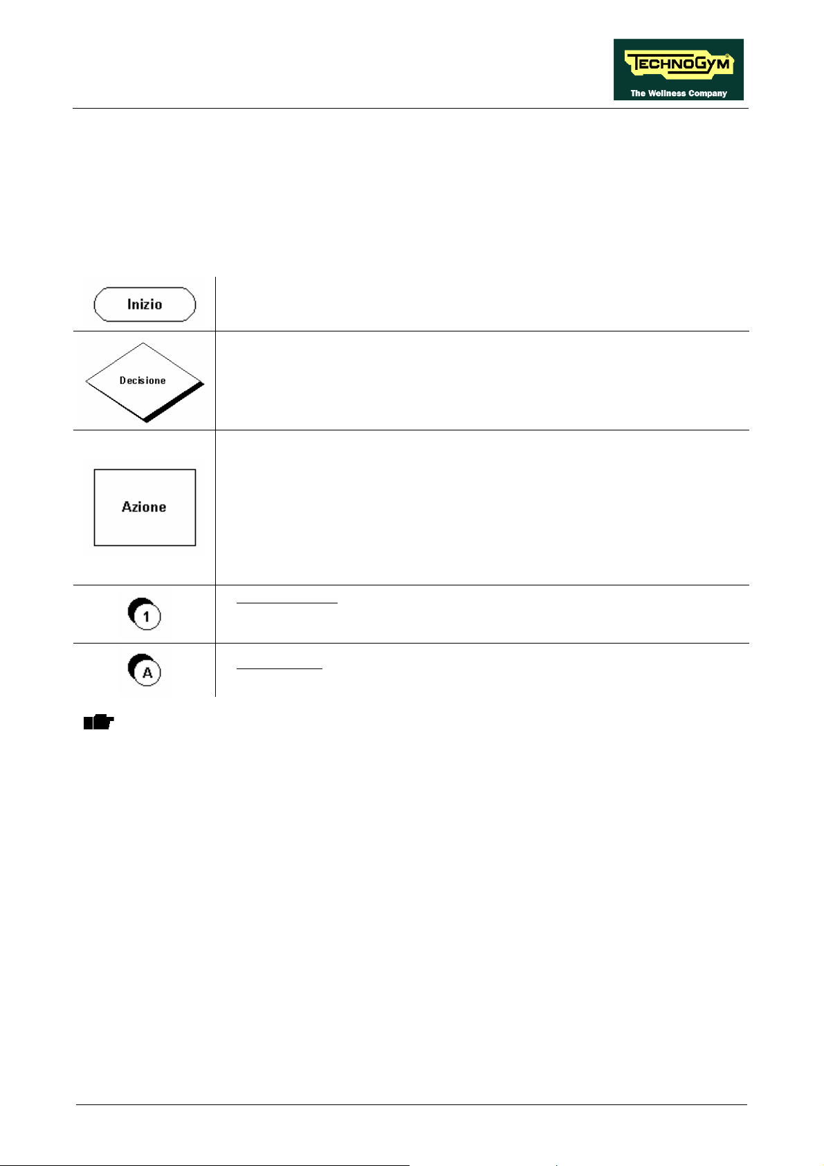
SYNCHRO EXCITE Class & Trend: Service & maintenance manual - rev. 2.0
6. TROUBLESHOOTING
The troubleshooting procedures are illustrated by means of flow diagrams. To facilitate
interpretation of these diagrams, the following standard box shapes are used:
This type of box is the START point of the troubleshooting procedure. It
typically contains a description of the problem or malfunction.
This type of box represents a decision point in the troubleshooting procedure.
It typically contains a description of the CHECK to be made, with an outcome
that is either a positive (YES) or negative (NO) response.
This type of box is a step in the troubleshooting procedure where an ACTION
must be carried out. It typically contains a description of the ACTION
necessary to resolve the problem Therefore, after executing the specified
ACTION:
1. Check whether the problem has been resolved;
2. If the problem persists, it is recommended to resume the troubleshooting
procedure from the point before the action was carried out.
A circled number (such as that shown on the left) next to a box of the
troubleshooting procedure indicates that more detailed instructions for
performing that particular check or action are provided below the flowchart.
A circled letter (such as that shown on the left) is used to mark a point in the
The connectors indicated in the following pages, refer to 700 model’s LED Boards, unless
otherwise indicated.
procedure. Typically, this indicator is used in page changes.
Page 6.1
Page 56

SYNCHRO EXCITE Class & Trend: Service & maintenance manual - rev. 2.0
6.1. TROUBLESHOOTING SERVICE MENU: ACTIVE
WELLNESS TV MODELS
The machine configuration procedure is invoked, when the machine is in standby mode, by pressing
the top right hand, the bottom left hand and the bottom right hand corner in sequence, as shown in
the picture below.
The machine display will shows a window from where you can access the different configuration
menus, using the proper password.
To access the menu, type in the password 2411 and press ENTER key to confirm or BACK key to
back forward.
At this point the machine display will shows the different parameters of the menu. To exit the
TROUBLESHOOTING menu press HOME key.
Pagina 6.2
Page 57

SYNCHRO EXCITE Class & Trend: Service & maintenance manual - rev. 2.0
Here below have been detailed all the parameters of the menu.
6.1.1. I2C DEVICE TEST
The I2C Device test checks the communication following the 32K and 256K memories. The test
can have two outcomes:
• “Test Successful”: Signifies that data packets were successfully transmitted and received
toward the display board.
• “EEPROM Error”: Signifies that the display board has communication problems with the memories.
6.1.2. CSAFE COM TEST
The test checks the communication on CSafe ports. The test can have two outcomes:
• “Test Successful”: This means that the test was completed successfully, i.e. that serial
communications on the selected port are correct.
• “Error COM1”: This means that the outcome of the test was negative.
The “CSafe COM test” done on a machine which CSafe port is not plugged with the monitor
plug described at chapter 4 of the Service & Maintenance manual.
6.1.3. LOW KIT COM TEST
The test checks the communication with the Low kit. The test can have two outcomes:
• “Test Successful”: This means that the test was completed successfully, i.e. that serial
communications on the selected port are correct.
• “Error COM2”: This means that the outcome of the test was negative.
Page 6.3
Page 58

SYNCHRO EXCITE Class & Trend: Service & maintenance manual - rev. 2.0
6.1.4. TGS COM TEST
The test checks the communication with the TGS reader. The test can have two outcomes:
• “Test Successful”: This means that the test was completed successfully, i.e. that serial
communications on the selected port are correct.
• “Error COM3”: This means that the outcome of the test was negative.
The “TGS COM test” done on machine not provided with the key reader gives a fail
outcome.
6.1.5. DVT BOARD TEST
It’s a command that allows to divert the serial communication, usually between the Digital TV
boardand the CPU board, on the external CSafe port.
This function wich allows to connect an external device to the Digital TV board is not used at the
moment.
Once the function has been launched it is necessary to switch off and switch on again the
machine to reinstate the correct connection.
Pagina 6.4
Page 59

SYNCHRO EXCITE Class & Trend: Service & maintenance manual - rev. 2.0
6.2. SERVICE TROUBLESHOOTING MENU: MODELLI LED
The configuration procedure is invoked when the machine is in standby mode, using a different
procedure for the 500 and 700 models.
• Accessing configuration of 500 models
Simultaneously press the ENTER, ↑, CLEAR keys. The following prompt appears on the display:
ENTER PASSWORD:
To access the procedure, type in the password 2501 which protects against unauthorized access and
press “Enter” to confirm. To enter the password, increase or decrease the displayed value using the
↑ and ↓ keys, or use the +/- GOAL keys to scroll through and modify the individual digits.
At this point there are two options available:
↑ = Tech Config
↓ = Troubleshooting
Press numeric key ↑ to access the menu for configuring technical parameters; the machine display
will begin showing the current configuration, structured as in the diagram below:
• Accessing configuration of 700 models
Simultaneously press the keys 369 for 700 LED models, whereas on 700 Wellness TV models the
keys 0369 must be pressed one after the other. The following prompt appears on the display:
ENTER PASSWORD:
To access the procedure, type in the password 2501 which protects against unauthorized access and
press the “Enter” key to confirm. At this point there are two options available:
1 = Tech Config
2 = Troubleshooting
Press numeric key 1 to access the menu for configuring technical parameters; the machine display
will begin showing the current configuration, structured as in the diagram below:
Page 6.5
Page 60

SYNCHRO EXCITE Class & Trend: Service & maintenance manual - rev. 2.0
TROUBLESHOOTING
AUTOMATIC TEST MANUAL TES T
I2C Devices Test
LED Test
SERIAL PORT S
TEST
TGS COM Te st
Low Ki t CO M Test
CSa fe CO M Test
MAN.KEYBOARD
TEST
To scroll through the list of available functions, press the + or – effort level keys to display the next
or the preceding item; confirm the choice by pressing ENTER. To cancel the operation, press the
CLEAR key for a few seconds.
The tests are divided into two groups: Automatic and Manual, and the prompt for a choice appears
immediately on accessing the troubleshooting menu.
6.2.1. AUTOMATIC TEST
The tests grouped under this section conduct checks on the machine’s operation in a fully automatic
manner. After selecting the desired test using the + and – effort level keys, press ENTER to initiate
the test and then await the result. Press ENTER again to continue, and use the CLEAR key to
return to the higher menu level, holding it down for a few seconds. The various tests are described
below.
6.2.1.1. I2C Devices Test
The I2C Devices test checks the communication following the 32K and 256K. The test can have
outcomes:
• “Test Successful, press Enter to continue”: Signifies that the transmission and reception of
data packets between the I2C devices and the display board was completed successfully.
• “EEPROM Error, press Enter to continue”: Signifies that the display board is having
problems communicating with its memories.
Pagina 6.6
Page 61

SYNCHRO EXCITE Class & Trend: Service & maintenance manual - rev. 2.0
6.2.1.2. LED Test
The LED test checks the functioning of the display by lighting all the LEDs in the matrix. It also
tests the buzzer by changing the frequency to produce a variation in the tone of the sound.
There is no message displayed concerning the outcome of this test, which must therefore be
checked visually.
6.2.1.3. Serial Ports Test
The serial ports test checks the communications on the following interface ports:
• CSafe COM test;
• Low Kit COM test;
• TGS COM test.
Using the + and – effort level keys, select the desired test item and confirm by pressing ENTER.
The test can have two outcomes:
• “Test Successful, press Enter to continue”: This means that the test was completed
successfully, i.e. that the communications on the selected serial port are functioning correctly.
• “COMx error, press Enter to continue”: This means that the outcome of the test was negative:
the message will specify COM1 in the case of the CSafe COM test, COM2 in the case of
communications with the low kit, or COM3 in the case of the TGS COM test.
The “TGS COM test” done on machine not provided with the key reader gives a fail outcome.
The same if the “CSafe COM test” is done on a machine which CSafe port is not plugged with
the monitor plug described at paragraph: 4.4. “Monitor plug for CSafe port”.
6.2.2. MANUAL TEST
The tests grouped under this section conduct checks on the machine’s operation in a fully automatic
manner. After selecting the desired test using the + and – effort level keys, press ENTER to initiate
the test and then await the result. To exit test mode, press and hold down the CLEAR key for a few
seconds.
6.2.2.1. Man. Keyboard Test
The m
the test by pressing ENTER, the message “Press all buttons (beep=OK)” appears on the display.
Pressing each key will produce an audible signal; if a key does not produce the beep it means it is
not working properly.
anual keyboard test checks the functioning of all the keys on the keyboard. After accessing
Page 6.7
Page 62

SYNCHRO EXCITE Class & Trend: Service & maintenance manual - rev. 2.0
6.3. THE DISPLAY FAILS TO ILLUMINATE
This error occurs when the power supply voltage is not reaching the upper assembly.
6.3.1. 500 AND 700 MODELS
TH E DIS P LAY
DOES NOT
ILLUMINATE
NO
Does the wall outlet suppl y the
correct voltage?
Plug th e m achine i nto a
work i ng el ectrical outlet
YES
I s the m ai ns lead OK ?
YES
Ar e the fus es O K?
YES
Ar e the LEDs on the
Displ ay boar d l i t on?
NO
Replace the mains lead
NO
Replace the fuses
1
YES
Replace the Displ ay
board
Pagina 6.8
NO
A
Continued on the following page
Page 63

SYNCHRO EXCITE Class & Trend: Service & maintenance manual - rev. 2.0
A
NO
Chack the cabl e that
connect t he Low Kit
with High Kit.
YES
Is the AC v oltage at the
input of the brake board
correct?
YES
Are the DC v oltages at the
output of the Barke board
correct?
NO
Replace the brak e
board
2
NO
4
Is the AC v oltage at the
output of the power ent ry
module cor rect?
YES
Replace
ELT-00
cable
3
NO
Replace the power
entry m odul e
Follow the procedure step by step to correctly diagnose the problem. Take particular care with the
checks highlighted by circled numbers, which are described in detail below:
(1) Check the LEDs 1 and 2 (green and yellow), of the Display Board, are correctly lit on.
(2) Place the tester probes across pins 3 and 1 of CN4 connectors on the Brake Board The
measured value should be approximately 220 VAC or 110 VAC depending on the mains
voltage.
(3) Slightly lift up the fast-on on the machine power entry module. Place the tester probes across
the live and neutral pins on the same connector. The measured value should be approximately
220 VAC or 110 VAC depending on the mains voltage.
(4) Using a tester, check that all the output voltages on connector CN1 of the Brake board. The
measured value should be:
• +12 Vdc between pins 6-2;
• +5 Vdc between pins 7-3.
(5) Check the continuity of the signal through ELT-04 and ELT-05 cables, which connect the
High Kit with Low Kit. Check also they are correctly connected and in a good state of wear,
replace if necessary.
If you replace Display board/Brake board, check that its SW version is updated, otherwise
install the last version.
Page 6.9
Page 64
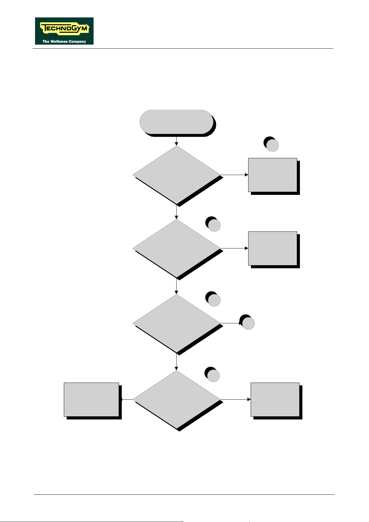
SYNCHRO EXCITE Class & Trend: Service & maintenance manual - rev. 2.0
6.3.2. 500SP AND 700SP MODELS
The problem may be caused by the display Board don’t receiving the speed signal
THE DISP LAY
DOES NOT
ILLUMINATE
1
Is the user pedaling?
YES
Are the LEDs on the
Display board lit on?
NO
Are the LEDs on the Brake
board, lit on while
pedaling ?
NO
Correct operation: after
30 seconds without
pedali ng the m achine
swi tches off
2
YES
Replace the Di splay
board
3
NO
B
Pagina 6.10
Replace the
ELT-04 and/or ELT-05
cables
YES
YES
Are the DC voltages at the
output of the brake board
correct?
4
NO
Replace the Brake
board
Continued on the following page
Page 65

SYNCHRO EXCITE Class & Trend: Service & maintenance manual - rev. 2.0
B
5
Replace the Brake
board
YES
Is t h e R PM signal and the
DC v olt age at the input t o
the brake board c orr ec t ?
NO
Replace t he Stat or
Follow the procedure step by step to correctly diagnose the problem. Take particular care with the
checks highlighted by circled numbers, which are described in detail below:
To speed up the troubleshooting procedure, check the state of the power indicator LEDs on the
various circuit boards.
(1) Check if the machine stays on for 30 seconds after having stopped pedalling. If the machine
switches off in few seconds, check if the fuse on the ELT-01cable is blown. Than check the
battery charge, if it isn’t about 12Vdc, recharge the battery for 8 hour with an external power
pack, without using the machine.
(2) Check the LEDs 1 and 2 (green and yellow), of the Display Board, are correctly lit on.
(3) Check if the LEDs 1 and 2 (green and yellow) of the Brake Board, are correctly lighting on,
as described in paragraph: 3.1.7. “Brake board”.
(4) Using a tester, check that all the output voltages on connector CN1 of the Brake board. The
measured value should be:
• +12 Vdc between pins 6-2;
• +5 Vdc between pins 7-3.
(5) Using a tester, check the voltage on connector CN3 of the Brake board. The measured value
should be 16-19 Vdc, between pins 1 e 2, nearly at 50 RPM. Use a tester, to estimate the RPM
signal on the CN3 connector of the Brake board. The measured value should be
approximately 30 Vac between pin 3 and a ground point.
If you replace Display board/Brake board, check that its SW version is updated, otherwise
install the last version.
Page 6.11
Page 66
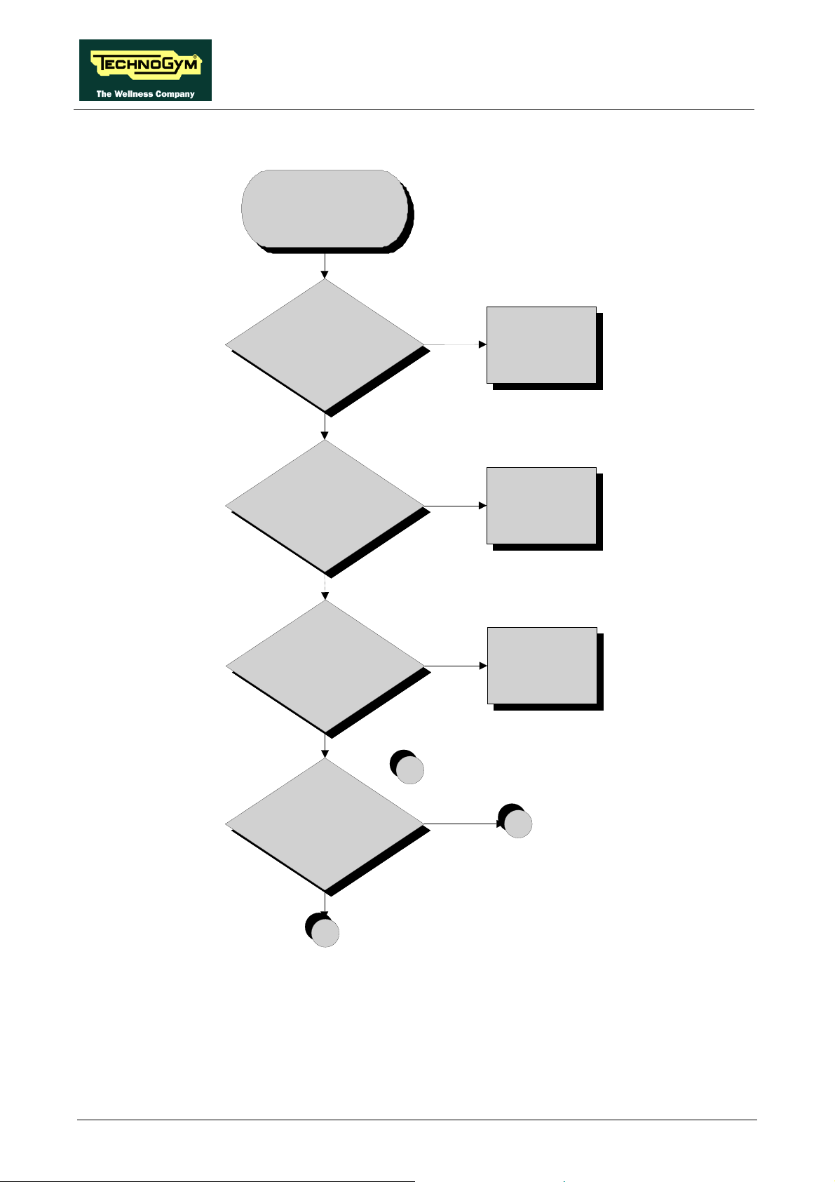
SYNCHRO EXCITE Class & Trend: Service & maintenance manual - rev. 2.0
6.3.3. 700WTV WELLNESS TV MODELS
THE DISP LAY
DOES NOT
ILLUMINATE
Does t he wall out l et s uppl y t he
correc t v oltage?
YES
NO
Plug the mac hi ne int o a
working elect ric al out l et
Is the mains lead OK?
YES
Are the f uses OK?
YES
Are the LED on t he
Dis pl ay board li t on?
NO
Replace t he m ai ns lead
NO
Replace t he f us es
1
YES
A
Pagina 6.12
NO
B
Continued on the following page
Page 67

SYNCHRO EXCITE Class & Trend: Service & maintenance manual - rev. 2.0
A
2
Start ex ercisi ng
by c hoosing "Quick -St a rt "
mode and press on t he Touc h-
Sensors: I s t he resis tanc e
change?
Do you hear beep
sound?
YES
NO
Replace C PU board
Replace t he LC D i nv ert er.
Does t h e problem
persists?
YES
Replace LC D
NO
Def ec t i v e LCD i nv et er
Continued on the following page
Page 6.13
Page 68
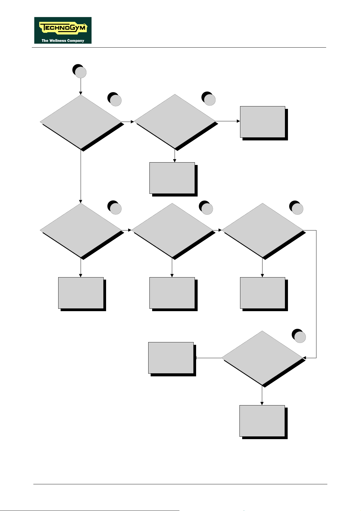
SYNCHRO EXCITE Class & Trend: Service & maintenance manual - rev. 2.0
B
NO
Is t he v olt age at t he input
of t he Brake board
correct?
YES
Are the v olt ages at the
output of t he Brak e board
correct?
NO
3
NO
Is the v olt age at t he
output of the power ent ry
module c orre c t ?
4
NO
Replac e the power
entry modu le
YES
Replac e ELT-00 c able
5
YES YES YES
Are the v olt ages on t he
patc h connec t or s 1 and 3
are corr ec t?
NO
6 7
Are the v olt age s at t he
input of t he D igital TV
board correct ?
NO
Replac e t he Bra k e
board
Replace
ELT-04 and/or ELT-05
cables
Replac e C PU board
YES
Replac e CU169 c able
8
Are the v olt ages at the
input of t he C PU board
correct?
NO
Replac e C U 169 c abl e
Pagina 6.14
Page 69

SYNCHRO EXCITE Class & Trend: Service & maintenance manual - rev. 2.0
Follow the procedure step by step to correctly diagnose the problem. Take particular care with the
checks highlighted by circled numbers, which are described in detail below:
(1) Check the LED D41 (green) of the display board, is correctly lit on.
(2) Start exercising in “Quick-Start” mode and check if the resistance change and a beep sound is
being produced when you click on the touch sensor buttons.
(3) Place the tester probes across pins 3 and 1 of CN4 connectors on the Brake board The
measured value should be approximately 220 VAC or 110 VAC depending on the mains
voltage.
(4) Slightly lift up the fastons on the machine power entry module. Place the tester probes across
the live and neutral pins on the same connector. The measured value should be approximately
220 VAC or 110 VAC depending on the mains voltage.
(5) Using a tester, check that all the output voltages on connector CN1 of the Brake board. The
measured value should be:
• +12 Vdc between pins 6-2;
• +5 Vdc between pins 7-3.
(6) As for step (5) but on patch connectors 1 and 3 of CU195 cable.
(7) Place the tester probes across pins 1 and 2 of J1 connectors on the Digital TV board. The
measured value should be +5Vdc.
(8) Place the tester probes across pins 2 and 6 of CN20 connectors on the CPU board. The
measured value should be +12Vdc.
If you replace Display board/Brake board, check that its SW version is updated, otherwise
install the last version.
The TV and RADIO channels is located in the Digital TV in the CPU Board and must
necessarily be present. This means that when even one of the two boards will be replaced,
should be re-stored channels through search or transferring from another machine via TGS
key or cable transfer.
Page 6.15
Page 70

SYNCHRO EXCITE Class & Trend: Service & maintenance manual - rev. 2.0
6.4. THE TOUCH SCREEN DOES NOT WORK / IT’S NOT
CALIBRATED
TOUCH SCREEN
DOES NO T WO RK /
NOT CALIBRAT ED
Check and update the HW
and SW related to the
Touch Scree n
1
2
YES
YES
Touch Scree n not
calibrated
Defect iv e Touch Screen
Replace C PU board
NO
Carry out the Touch Sc r een
calibrat ion proc edure.
Does it work correctly ?
NO
Replace the Touch Screen.
Does it work correctly ?
Follow the procedure step by step to correctly diagnose the problem. Take particular care with the
checks highlighted by circled numbers, which are described in detail below:
(1) It’s recommended to upgrade the HW and SW of machine display to the last version, due to
the steady work on the product for its improvement. Please refers to the proper section of the
TG Direct web site: “Parts catalogue” and “Product release”.
(2) Carry out the Touch Screen calibration procedure as detailed at paragraph 9.9. “Touch screen
calibration”.
Pagina 6.16
Page 71
SYNCHRO EXCITE Class & Trend: Service & maintenance manual - rev. 2.0
6.5. NO AUDIO SOUND
This error can be due to an incorrect machine configuration, or to problems with the audio circuit.
NO AUDI O SOUND
1
Replace t he C PU board
NO
Is t he TV st andard correc tly
conf igured?
YES
Replace t he headphone jac k .
Does it work?
NO
Replac e headphone
connection cable. Does it
work?
NO
YES
YES
Correc t ly conf igure t he
"TV Standard"
parameter
Defect iv e headphone
jack
Defect iv e headphone
cable
Follow the procedure step by step to correctly diagnose the problem. Take particular care with the
checks highlighted by circled numbers, which are described in detail below:
(1) Carry out the configuration procedure as detailed at paragraph 9.5.6. “TV Standard”.
If you replace Display board/Brake board, check that its SW version is updated, otherwise
install the last version.
The TV and RADIO channels is located in the Digital TV in the CPU Board and must
necessarily be present. This means that when even one of the two boards will be replaced,
should be re-stored channels through search or transferring from another machine via TGS
key or cable transfer.
Page 6.17
Page 72
SYNCHRO EXCITE Class & Trend: Service & maintenance manual - rev. 2.0
6.6. NO TV PICTURE
Check that the machine is connected to an antenna signal
This error can be due to an incorrect machine configuration, or to problems with the antenna signal.
ATTENTION - ONLY FOR JAPAN: Before to carry out the following troubleshooting, check
that the B-CAS card is correctly inserted on the TV Digital Board.
NO T V PICT URE
On the ot her m ac hines y ou see
the TV?
YES
Check i f the ant enna c able is
properly co nnec ted
YES
Connec t t he m achines at one
antenna soket sure working.
NO
Chec k t he ant e nna
signal.
1
NO
Connect the c able
NO
Replace t he ant enna
soket
Pagina 6.18
A
Continued on the following page
Page 73

SYNCHRO EXCITE Class & Trend: Service & maintenance manual - rev. 2.0
A
YES
2
Is the TV standard c orrec tly
conf igured?
YES
Check t he Ant enna
signal.
YES
Chec k the c ondi t ions of
antenna cable.
It is CU-198 ok?
YES
NO
Configure the
"TV standa rd"
parameter
3
4
NO
Replace t he C U -1 98
cable.
Replace t he D ig it a l TV
board
and / or
the CPU board
CU160 cable defect iv e
YES
Replace t he C U 160 cable.
Working?
NO
Follow the procedure step by step to correctly diagnose the problem. Take particular care with the
checks highlighted by circled numbers, which are described in detail below:
Page 6.19
Page 74

SYNCHRO EXCITE Class & Trend: Service & maintenance manual - rev. 2.0
(1) Check that the antenna cable is correctly connected to the TUNER on Digital TV board.
(2) Carry out the configuration procedure as detailed at paragraph 9.5.6. “TV Standard”.
(3) Check that the antenna signal matches with the minimal requested specifications detailed at
paragraph: 5.2. “Installation requirements and specifications for Wellness TV machines”.
(4) Check the state of wear of the antenna cable CU198, and that it properly works.
If you replace Display board/Brake board, check that its SW version is updated, otherwise
install the last version.
The TV and RADIO channels is located in the Digital TV in the CPU Board and must
necessarily be present. This means that when even one of the two boards will be replaced,
should be re-stored channels through search or transferring from another machine via TGS
key or cable transfer.
Pagina 6.20
Page 75

SYNCHRO EXCITE Class & Trend: Service & maintenance manual - rev. 2.0
6.7. THE RADIO DOES NOT PLAY
With the ANALOGIC signal, the radio signal can only be acquired from an aerial antenna
signal. If the machine is connected to a digital source (or to a satellite antenna) it will be
impossible to use the radio function.
If ACTIVE Wellness TV interface is installed, check that the parameter: 9.3.17. “Radio” is
correctly set.
It is now possible only the tuning of the digital band and not more the analogue one.
THE RADIO DO ES NOT
PLAY
Chec k if t h e ant enna
signal is good
Is the tuner connected to a
terr es t r ial an t enna c ab le
without any ty pe of interruption
(multiple x er, TV dis t r ibution
module)?
NO
Connec t a s i gnal t ha t
meets t hes e
requirements
YES
NO
Is the TV channel sound OK?
Perform t he "Audio does
not work" procedure
YES
1
NO
Replace the CPU board.
Does i t work correc tly ?
YES
Defective CPU board
Follow the procedure step by step to correctly diagnose the problem. Take particular care with the
checks highlighted by circled numbers, which are described in detail below:
Page 6.21
Page 76

SYNCHRO EXCITE Class & Trend: Service & maintenance manual - rev. 2.0
(1) Check that the antenna signal matches with the minimal requested specifications detailed at
paragraph: 5.2. “Installation requirements and specifications for Wellness TV machines”.
If you replace Display board/Brake board, check that its SW version is updated, otherwise
install the last version.
The TV and RADIO channels is located in the Digital TV in the CPU Board and must
necessarily be present. This means that when even one of the two boards will be replaced,
should be re-stored channels through search or transferring from another machine via TGS
key or cable transfer.
Pagina 6.22
Page 77

SYNCHRO EXCITE Class & Trend: Service & maintenance manual - rev. 2.0
6.8. THE IPOD DOES NOT WORK
THE iPOD DOES
Check the audio
con ne ct i on syst e m
YES
3
NOT WORK
E nter t he audio/ video files
lists. Can you see the list of all
the f iles uploaded on t he iP od?
NO
Replace the Docking
stati on board
2
SI
Is the i P od detect ed by the
m achine?
1
NO
Update t he iP od S W version
4
5
Has been the device enabled
from t he proper
functi on in t he user m enu?
NO
E nable t he iP od
YES
6
Check the CU167 cable
connection.
Is the i P od detect ed by the
m achine?
NO
Is the volt age at the input of t he
docking stat ion correct?
NO
A
YES
OK
7
YES
Replace the docking
stati on board
Continued on the following page
Page 6.23
Page 78

SYNCHRO EXCITE Class & Trend: Service & maintenance manual - rev. 2.0
A
8
Replace CU169 cable
YES
Is the voltage on t he patc h
connector correct?
11
NO
Is the voltage at the out put of
the AUX board correct ?
NO
Is the v olt age at t he i nput o f th e
AUX board correc t ?
NO
Is the voltage at the out put of
the D i git a l TV board c orrect ?
YES
Replace CU167 cable
9
YES
Replac e t he AU X board
10
YES
Replac e CU 166 c able
NO
Replace D igital TV
board
Follow the procedure step by step to correctly diagnose the problem. Take particular care with the
checks highlighted by circled numbers, which are described in detail below:
Pagina 6.24
Page 79

SYNCHRO EXCITE Class & Trend: Service & maintenance manual - rev. 2.0
(1) Switch on the machine, connect the iPod on the docking station and check that the device is
correctly detected by the machine.
(2) Check that the audio/video files uploaded in the iPod are visible and selectable through the
WTV interface.
(3) Carry out the troubleshooting procedure 6.5. “No audio sound”.
(4) To update the iPod SW you just need to connect to iTunes and it automatically upgrades to the
last version.
(5) Enable the iPod control as detailed at paragraph 9.3.18. “iPod connection option” in the user
menu.
(6) The CU167 cable has identical connectors on either end then it can sometimes be connected
the wrong way round. Check that the connector marked with a blue sign is connected on the
AUX connectors board.
(7) Place the tester probes across pins 8-9 of the connector on the docking station board where
the CU167 cable is connected. The measured value should be 5 Vdc.
(8) As for step (7) but across pins 6-7 of the connector on the AUX connectors board where
CU167 is connected.
(9) As for step (7) but across pins 9/10-13 of the connector on the AUX connectors board where
CU166 is connected.
(10) As for step (7) but across pins 9/10-13 of the connector J9 on the Digital TV board.
(11) Place the tester probes across pins 3-7 on patch connector of CU169 cable. The measured
value should be 5 Vdc.
If you replace Display board/Brake board, check that its SW version is updated, otherwise
install the last version.
Page 6.25
Page 80

SYNCHRO EXCITE Class & Trend: Service & maintenance manual - rev. 2.0
6.9. “THE EQUIPMENT IS LOCKED (COM)” MESSAGE ON
DISPLAY
This error message can be caused by loss of communication between the lower and upper
assemblies.
The error is displayed by a massage and stored in the “Errors Log” section.
To reinstate communications between the lower and upper assemblies:
(1) Check that cables ELT-06 and ELT-07 are correct, using the Test Box Excite and replace if
necessary;
(2) Try replacing the brake board and the display board in turn, and check whether the
communication works.
If you replace Display board/Brake board, check that its SW version is updated, otherwise
install the last version.
Pagina 6.26
Page 81
SYNCHRO EXCITE Class & Trend: Service & maintenance manual - rev. 2.0
6.10. THERE IS NO RESISTANCE
The machine will not produce resistance if:
• the display board is not receiving a speed signal;
• the brake board is not generating current;
• the brake is defective.
THERE IS NO
RESISTANCE
Are the W att and SPM value s
shown on the di s play dif f erent
from zero?
NO
Carry out t h e "The speed
signal is incorrect "
troubles hoot ing procedure
SELF-POWERED
YES
1
NO
Does t he br ak e board s upply
tens ion at t he brake?
Replace t he br ak e board
YES
2
Is t he res i s tanc e on t he Brake
winding
more or less 5 Ohm?
NO
Replac e the brake
Replace
ELT-02 cable
NO
YES
Does t he i nput of brake rec eiv e
tens i on f rom t he bra k e?
3
YES
Replac e the brak e
Page 6.27
Page 82
SYNCHRO EXCITE Class & Trend: Service & maintenance manual - rev. 2.0
Follow the procedure step by step to correctly diagnose the problem. Take particular care with the
checks highlighted by circled numbers, which are described in detail below:
(1) Place the tester probes across pins 1-2 of the connector CN2 on the brake board and exercise
at a speed of 60 RPM. You should measure a Vdc which increases according to the exercise
level.
(2) As for step (1) but across the two fast-on at the input of the brake.
(3) As for step (1) but with everything reconnected, and across the brake winding.
If you replace Display board/Brake board, check that its SW version is updated, otherwise
install the last version.
Pagina 6.28
Page 83

SYNCHRO EXCITE Class & Trend: Service & maintenance manual - rev. 2.0
6.11. THE RESISTANCE IS INCORRECT
The machine will produce an incorrect resistance if:
• the mechanical components are not in perfect condition;
• the speed measurement is incorrect;
• the brake board is defective;
• the brake is defective.
THE
RESISTANCE IS
INCORRECT
Carry out the St an dard Sett i ng
procedure
Are the mec hanic s of the
mac hine in good c ondition?
YES
Carry out t he "Speed
signal is I ncorrect "
troubles hoot i ng proc edure
1
2
NO
Repair t he f aulty
mec hanic al parts
3
Replac e t he Brak e
winding
YES
Does t he brak e board out put
the correct current to the brake
winding?
NO
Replace the brake board
Page 6.29
Page 84

SYNCHRO EXCITE Class & Trend: Service & maintenance manual - rev. 2.0
Follow the procedure step by step to correctly diagnose the problem. Take particular care with the
checks highlighted by circled numbers, which are described in detail below:
(1) Carry out the “Standard Setting” procedure as detailed at paragraph 9.5.5. “Standard
settings”.
(2) Check that the mechanical system, consisting of the pedals, belt and brake, moves smoothly
and without higher than normal friction or resistance.
(3) Measure the voltage supplied by the brake board to the winding. In “Quick Start” mode,
select the effort level and check that the value is different from 0.
If you replace Display board/Brake board, check that its SW version is updated, otherwise
install the last version.
Pagina 6.30
Page 85

SYNCHRO EXCITE Class & Trend: Service & maintenance manual - rev. 2.0
6.12. THE SPEED SIGNAL IS INCORRECT
The speed signal is incorrect if:
• The brake disk is incorrectly fixed to the flywheel;
• The speed sensor is defective;
• The brake board is defective.
TH E SPEED
SIGNAL IS
INCORRECT
Defectiv e SW
YES
Carry out t he St andard Setting
procedure
YES
Does t he s peed s ensor s en d
the c orrec t s ignal t o the brak e
board?
YES
Update the brak e board SW.
Is t h e s peed s i gnal correc t?
1
2
NO
Replace t he
speed s ensor
(generat or on SP m ode ls )
3
NO
Replace the Brake board
Follow the procedure step by step to correctly diagnose the problem. Take particular care with the
checks highlighted by circled numbers, which are described in detail below:
Page 6.31
Page 86

SYNCHRO EXCITE Class & Trend: Service & maintenance manual - rev. 2.0
(1) Carry out the “Standard Setting” procedure as detailed at paragraph 9.5.5. “Standard
settings”.
The speed sensor detects the heads of these bolts.
(2) Powered models: Place the tester probes across the terminals of the speed sensor. The
measured signal should be that indicated in Figure 3.2-1. In addition,
when pedaling at 80 RPM the frequency of the signal should be 136
Hz.
Self-Powered models: Check the signal on ELT-01 cable. The measured signal should be
that indicated in Figure 3.2-1. In addition, when pedaling at 80 RPM
the frequency of the signal should be 136 Hz.
The speed signal can also be observed qualitatively, using a multimeter. The value should be 0
Vdc when the machine is stopped, and gradually increase as the speed increases.
(3) Update the low kit SW uploading both firmware and brake table. At the end carry out the
“Default setting” procedure for the low kit parameters.
If you replace Display board/Brake board, check that its SW version is updated, otherwise
install the last version.
Pagina 6.32
Page 87

SYNCHRO EXCITE Class & Trend: Service & maintenance manual - rev. 2.0
6.13. THE MACHINE DOES NOT READ THE TGS
The machine displays this error if the TGS reader is not working properly, or if it is not supplied by
the display board.
TH E MA C H INE DO ES
NOT READ THE TGS
1
Replace the dis play board
NO
Is the voltage at the input to the
TGS reader correct?
NO
Is t he v oltage at t he out put to
the D isplay board correc t?
A
Is the serial c om m unic at i on link
between th e dis pl ay board and
the TGS reader OK?
YES
A
2
YES
Replace c able C BQ- 32
3
YES
Replac e the TGS reader
NO
3
Replac e the display board
NO
Replace t he TGS reader. I s t he
com m unicat i on lin k bet ween t he
displ ay board and the TGS
reader OK?
YES
TGS reader defect iv e
Follow the procedure step by step to correctly diagnose the problem. Take particular care with the
checks highlighted by circled numbers, which are described in detail below:
Page 6.33
Page 88

SYNCHRO EXCITE Class & Trend: Service & maintenance manual - rev. 2.0
(1) Place the tester probes across pins 1 and 8 of connector CN1 of the TGS reader. The
measured value should be +12 Vdc.
(2) As for step (1) but across pins 1 and 9 of connector CN8 on the display board.
(3) Use the serial communications test described at paragraph 6.2.1.3 “Serial Ports Test”.
If you replace Display board/Brake board, check that its SW version is updated, otherwise
install the last version.
Pagina 6.34
Page 89

SYNCHRO EXCITE Class & Trend: Service & maintenance manual - rev. 2.0
6.14. THERE IS NO HEART RATE SIGNAL
6.14.1. HFU TELEMETRIC RECEIVER
The machine displays this error if:
1. electromagnetic noise saturate the HR receiver which does not display any value due to a
specific SW filter which cut every signal, greater than 220 bpm;
2. the receiver is not working properly;
3. the receiver is not supplied by the display board.
TH ER E IS N O HR
SIGNAL
1
Carry out the
troubl es hoo t ing pr oc edur e
"THE TELEMETRIC
SIGN AL I S IN C OR R EC T"
2
YES
Replace the rec eiv er
3
YES
Replace ELT-16 cabl e
Replace display board
Is the supply voltage c orrect at
the inp ut t o the receiv er?
NO
NO
Is the supply voltage c orrect at
the output of t he di s pl ay board?
Follow the procedure step by step to correctly diagnose the problem. Take particular care with the
checks highlighted by circled numbers, which are described in detail below:
(1) Carry out the troubleshooting procedure: 6.15. “The telemetric heart rate signal is incorrect”.
(2) Place the tester probes across pins 1 and 2 of connector CN1 of the receiver. The measured
value should be +5 Vdc.
(3) As for step (2) but across pins 1 and 8 of connector CN3 on the display board.
Page 6.35
Page 90

SYNCHRO EXCITE Class & Trend: Service & maintenance manual - rev. 2.0
6.14.2. HAND SENSOR
The machine displays this error if the HS interface board is not working, or if it is not supplied by
the display board.
For an easier and quicker diagnosis of the problem, we recommend to use the functions of Test
Box Excite.
THERE IS NO HR
SIGNAL
1
Check the earth connection
of t he m achine
2
A re the sensors correctly
connected to t he connectors
board?
YES
Is the connectors board
correctly connected to t he HS
interface board?
YES
Is the supply voltage correct at
the input t o the HS int erface
board?
NO
NO
NO
Reinstate t he connection
Reinstate t he connection
3
YES
Replace the HS interface
board
4
Pagina 6.36
Is the supply voltage correct on
the pat ch connector 6?
NO
A
YES
Replace the
E LT-31 cable
Continued on the following page.
Page 91
SYNCHRO EXCITE Class & Trend: Service & maintenance manual - rev. 2.0
A
5
YES
Replac e c ab l e E LT-19
Replace the dis pl ay boar d
NO
Is t he s uppl y vol t age co rr e c t at
the output of the di splay board?
Follow the procedure step by step to correctly diagnose the problem. Take particular care with the
checks highlighted by circled numbers, which are described in detail below:
(1) Check the earth connection of the machine using a tester to measure the resistance between
the ground pin on the power supply cable and the ground node to which the receiver is
connected inside the display. The value must be less than 1 (Ohm).
(2) Check the connections, referring to paragraph 2.7. “Wiring diagrams”.
(3) Place the tester probes across pins 2 and 1 of connector J3 on the HS interface board. The
measured value should be +5 Vdc.
(4) As for point (2) but on patch connector 6.
(5) As for step (2) but across pins 1 and 6 of connector CN4 on the display board.
Page 6.37
Page 92

SYNCHRO EXCITE Class & Trend: Service & maintenance manual - rev. 2.0
6.15. THE TELEMETRIC HEART RATE SIGNAL IS INCORRECT
The machine displays this error if the receiver is disturbed by sources of electromagnetic noise.
THE TELEMETRIC
HR SIG NAL IS
INCORRECT
1
Check t he eart h connection
of t he m achine
2
Are the m a c hines c orr ec t l y
spac ed by t he requi red m i nim um
distance?
YES
Is the re c ei v er c o rrect l y
posit ioned and are the
connect ing c ables proper ly
routed?
YES
Are there sources of
elect rom agnet ic nois e near t he
receiver?
NO
Reposit ion the mac hines
so t hey are adequately
spaced
3
NO
Correc t t he pos it i on of the
receiv er and the rout ing of
the c ables
4
YES
Mov e t h e m ac hin e away
from t he nois e s ourc e or
att enuat e the power of t he
noise
Pagina 6.38
NO
A
Continued on the following page
Page 93

SYNCHRO EXCITE Class & Trend: Service & maintenance manual - rev. 2.0
A
5
Replac e the rec ei v er
YES
Is the t ransm it ter i n good
working order?
YES
Is the transmitter always wit hin
the 90 cm range from t he rec eiv er
NO
NO
Us e a correct ly
funct ioni ng t r ans m itt er
Reposition the transmitter
withi n ra n ge
Follow the procedure step by step to correctly diagnose the problem. Take particular care with the
checks highlighted by circled numbers, which are described in detail below:
(1) Check the earthing of the machine using a tester to measure the resistance between the ground
pin on the power supply cable and the ground node to which the receiver is connected inside
the display. The value must be less than 1 (Ohm).
(2) For machine positioning layouts, use the following diagram as a reference.
Page 6.39
Page 94

SYNCHRO EXCITE Class & Trend: Service & maintenance manual - rev. 2.0
r
where the value in the diagram indicates the medium distance for signal reception during the
exercise (± 4” inches or 10 cm).
(3) Check that the cardio receiver has been assembled properly as described in the procedure: 7.4.
“Cardio receiver” , that is in good condition, work properly and the state of the band (ie
battery).
(4) To check for electromagnetic noise near the machine, use Test Box Excite as detailed here
below. You can use one of the following cables ELT16 (0WC00518AB), CBQ28
(0WC00390AC) or TRM28 (0WC00336AC) as connection cable.
Receiver
Connection
cable
HR receive
TEST BOX
EXCITE
The circuit lights the LED for each heart beat and/or disturbance received: in this way it is
possible to determine whether there is any interference, and identify its sources.
(5) Check the battery power level, using a tester if possible. Otherwise use a receiver or another
reference machine to check the operation up to a distance of about 90 cm from the receiver.
Pagina 6.40
Page 95
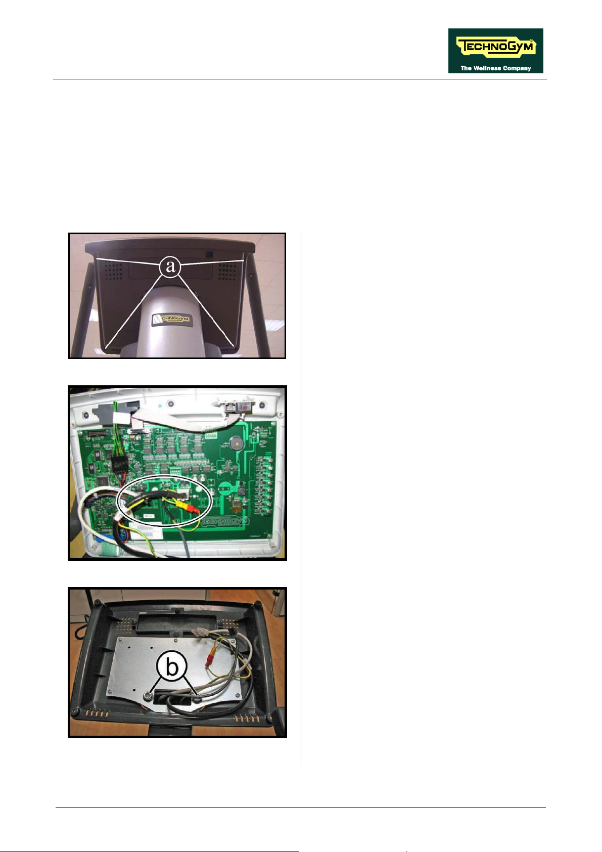
SYNCHRO EXCITE Class & Trend: Service & maintenance manual - rev. 2.0
7. DISASSEMBLY OF COMPONENTS
7.1. DISPLAY DISASSEMBLY
7.1.1. LED VERSION 500 AND 500SP
1. Turn off the machine and unplug the mains
lead from the wall outlet (Only for 500).
2. Back off the 4 screws (a) using a medium
Phillips screwdriver.
Figure 7.1-1
Figure 7.1-2
3. Unplug the connectors as indicated in the
figure at left [CN9-CN1-CN3].
4. Remove the display.
5. Back off the 2 screws (b), using an 8mm Hex
wrench, to remove the rear display support.
To reassemble the display, carry out the above
steps in reverse order.
Figure 7.1-3
Page 7.1
Page 96

SYNCHRO EXCITE Class & Trend: Service & maintenance manual - rev. 2.0
7.1.2. LED VERSION 700 AND 700SP
Figure 7.1-4
1. Turn off the machine and unplug the mains
lead from the wall outlet (Only for 700).
2. Back off the 4 screws (a) using a medium
Phillips screwdriver.
3. Unplug the connectors as indicated in the
figure at left [CN9-CN1-CN6-CN5-CN4].
4. Remove the display.
Figure 7.1-5
5. Back off the 2 screws (b), using an 8mm Hex
wrench, to remove the rear display support.
To reassemble the display, carry out the above
steps in reverse order.
Figure 7.1-6
Pagina 7.2
Page 97

SYNCHRO EXCITE Class & Trend: Service & maintenance manual - rev. 2.0
7.1.3. 700WTV VERSION (WELLNESS TV)
Turn off the machine and unplug the mains lead
from the wall outlet.
1. Back off the 4 screws (a) using a medium
Phillips screwdriver.
Figure 7.1-7
Figure 7.1-8
2. Unplug the connectors as indicated in the
figure at left [CN30-CN26-CN27-CN19CN21- CN22-CN25].
3. Remove the display.
4. Back off the 2 screws (b), using an 8mm Hex
wrench, to remove the rear display support.
To reassemble the display, carry out the above
steps in reverse order.
Figure 7.1-9
Page 7.3
Page 98

SYNCHRO EXCITE Class & Trend: Service & maintenance manual - rev. 2.0
7.2. DISPLAY BOARDS DISASSEMBLY
7.2.1. 500 AND 500SP VERSION
Carry out the operations described in
paragraphs: Errore. L'origine riferimento non
è stata trovata.“Errore. L'origine riferimento
non è stata trovata.”.
Then place the display on a work bench. It is
now possible to disassemble its circuit boards:
• The Display Board (A);
• The C-Safe Board (B).
Figure 7.2-1
Figure 7.2-2
Display Board (A):
1. Disconnect connectors (a) [CN2] of the
keyboard and (b) [CN8] of the CSafe board
from the Display board.
2. Back off the 5 screws (c) with a medium
Phillips screwdriver.
3. Remove the circuit board.
CSafe Board (B):
1. Disconnect connector (d) [CN8] of the C-
Safe from the Display board.
2. Remove the circuit board (e), slipping it off
from the top.
Pagina 7.4
Figure 7.2-3
Use again the hot glue to fix the
connectors, where necessary.
To reassemble the circuit boards, carry out the
above steps in reverse order.
Page 99

SYNCHRO EXCITE Class & Trend: Service & maintenance manual - rev. 2.0
7.2.2. 700 AND 700SP LED VERSION
Carry out the operations described in
paragraphs: Errore. L'origine riferimento non
è stata trovata.“Errore. L'origine riferimento
non è stata trovata.”.
Then place the display on a work bench. It is
now possible to disassemble its circuit boards:
Figure -7.2-4
• The Display Board (A);
• The C-Safe Board (B).
Display Board (A):
1. Disconnect connectors (a) [CN2] of the
keyboard and (b) [CN8] of the CSafe board
from the Display board.
2. Back off the 5 screws (c) with a medium
Phillips screwdriver.
3. Remove the circuit board.
Figure 7.2-5
Figure 7.2-6
CSafe Board (B):
1. Disconnect connector (d) [CN8] of the C-
Safe from the Display board.
2. Remove the circuit board (e), slipping it off
from the top.
Use again the hot glue to fix the
connectors, where necessary.
To reassemble the circuit board, carry out the
above steps in reverse order
Page 7.5
Page 100
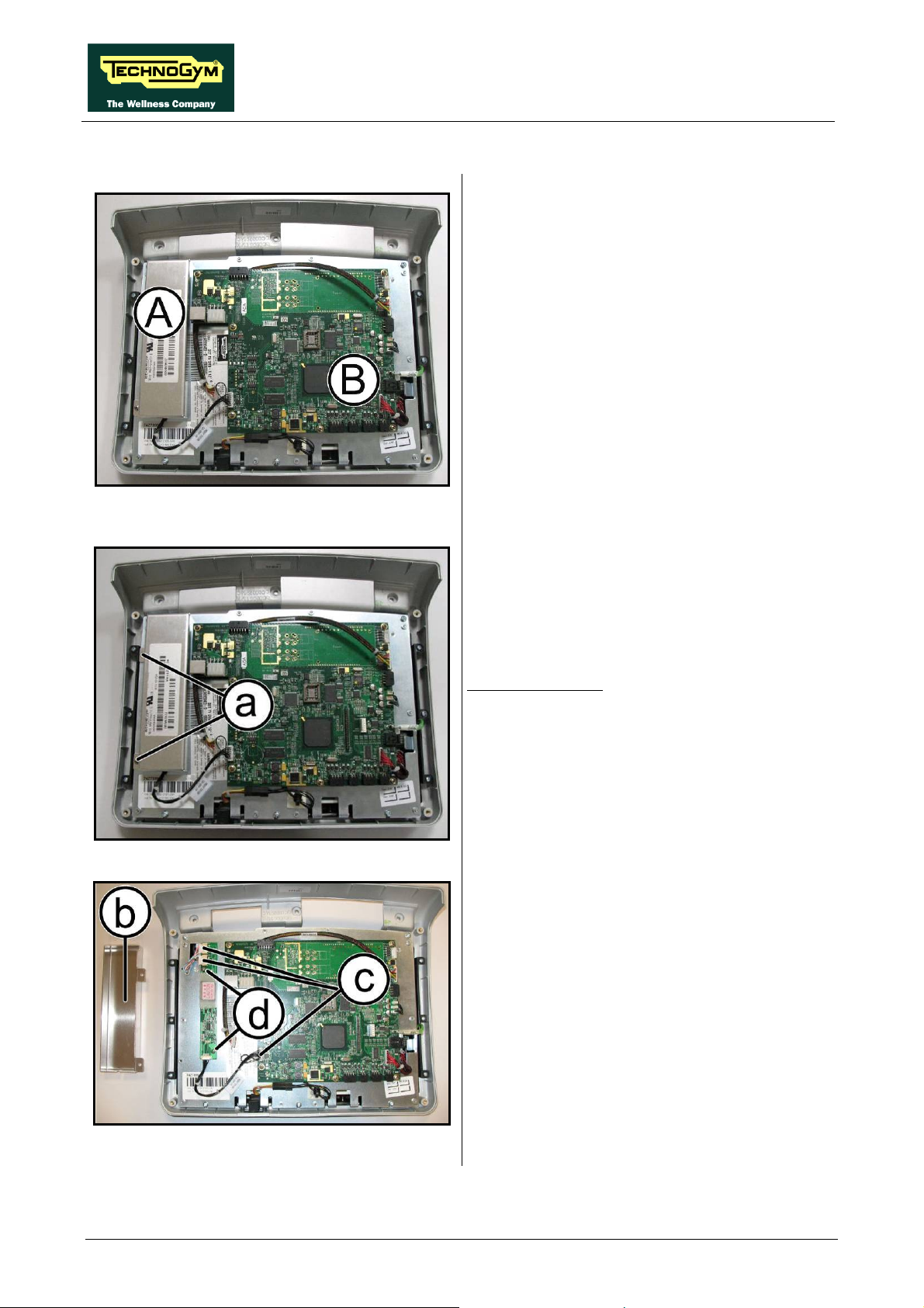
SYNCHRO EXCITE Class & Trend: Service & maintenance manual - rev. 2.0
7.2.3. 700WTV VERSION (WELLNESS TV)
Carry out the operations described in
paragraphs: Errore. L'origine riferimento non
è stata trovata.“Errore. L'origine riferimento
non è stata trovata.”.
Then place the display on a work bench. It is
now possible to disassemble its circuit boards:
And the circuit boards mounted on the rear
display support:
Figure 7.2-7
• The LCD inverter (A),
• The CPU Board (B).
• Digital TV Board
• Input AUX Board
Figure 7.2-8
Figure 7.2-9
LCD inverter (A):
1. Back off the 2 screws (a) with a medium
Phillips screwdriver
2. Remove the covering plate (b) of the LCD
inverter.
3. Disconnect the connectors (c) [CN2 – CN3-
CN5].
4. Back off the 2 screws (d), which fix the
board to the display plate.
5. Remove the LCD inverter.
Pagina 7.6
Continued on following page
→
 Loading...