

Technogym Step 500i SP, Step 500i, Step 700i, Step 700i S, Step 700i E Service Maintenance Manual
Page 1

SERVICE & MAINTENANCE MANUAL
REV. 1.4
Page 2

Page 3

The information contained in this manual is intended for QUALIFIED TECHNICIANS who have
completed a specific TECHNOGYM training course and are authorized to perform machine start-
up and adjustment procedures as well as extraordinary maintenance or repairs which require a
thorough knowledge of the machine, its operation, its safety devices and working procedures.
CAREFULLY READ THE INFORMATION CONTAINED IN
THIS MANUAL BEFORE PERFORMING ANY MAINTENANCE
PROCEDURES ON THE MACHINE
DANGEROUS VOLTAGES
PRESENT
NOTE
The information contained in this document is subject to change without notice.
Technogym does not guarantee this documentation in any way. Technogym shall not be held
responsible for any errors contained in this manual and declines all liability for accidents or
damages resulting from the supply, characteristics or use of this manual.
This document contains proprietary information that is protected by copyright. All rights reserved.
No part of this document may be photocopied, reproduced or translated into another language
without the prior written consent of Technogym.
The Technogym™ trademark is property of Technogym S.p.A.
The Step Excite™ trademark is property of Technogym S.p.A.
Page 4

Page 5

STEP EXCITE: Service & maintenance manual - rev. 1.4
Summary
1. GENERAL NOTICES ............................................................................................................................................. 1.1
1.1. INTRODUCTION...................................................................................................................................................1.1
1.2. RECOMMENDATIONS .......................................................................................................................................... 1.1
1.3. GENERAL RULES FOR REPAIR PROCEDURES ........................................................................................................ 1.2
2. TECHNICAL SPECIFICATIONS ........................................................................................................................ 2.1
2.1. PRODUCT CODES................................................................................................................................................. 2.1
2.2. AVAILABLE VERSIONS ........................................................................................................................................2.2
2.3. MECHANICAL CHARACTERISTICS ....................................................................................................................... 2.3
2.4. ELECTRICAL CHARACTERISTICS ......................................................................................................................... 2.3
2.5. CONFORMITY TO REGULATIONS.......................................................................................................................... 2.4
2.6. AMBIENT SPECIFICATIONS ..................................................................................................................................2.4
2.7. WIRING DIAGRAMS............................................................................................................................................. 2.5
2.7.1. 500i model........................................................................................................................................2.5
2.7.1.1. Powered version................................................................................................................................................................ 2.5
2.7.1.2. Cordless version................................................................................................................................................................ 2.6
2.7.2. 500i model – ARM board..................................................................................................................2.7
2.7.2.1. Powered version................................................................................................................................................................ 2.7
2.7.2.2. Cordless version................................................................................................................................................................ 2.8
2.7.3. 700i model........................................................................................................................................2.9
2.7.3.1. Powered version................................................................................................................................................................ 2.9
2.7.3.2. Cordless version.............................................................................................................................................................. 2.10
2.7.4. 700i model – ARM board................................................................................................................2.11
2.7.4.1. Powered version.............................................................................................................................................................. 2.11
2.7.4.2. Cordless version.............................................................................................................................................................. 2.12
2.7.5. 700iE WTV model...........................................................................................................................2.13
2.7.5.1. Wellness TV Touch screen NCB version....................................................................................................................... 2.13
2.7.5.2. Wellness TV Touch screen UB version ......................................................................................................................... 2.14
2.8. WIRING ............................................................................................................................................................ 2.15
3. PRINCIPLES OF OPERATION............................................................................................................................ 3.1
3.1. BLOCK DIAGRAM................................................................................................................................................ 3.1
3.1.1. Display boards..................................................................................................................................3.2
3.1.1.1. 500i and 500i SP versions................................................................................................................................................. 3.2
3.1.1.2. 500i ARM and 500i SP ARM models .............................................................................................................................. 3.3
3.1.1.3. 700i and 700i SP versions................................................................................................................................................. 3.3
3.1.1.4. 700i ARM and 700i SP ARM models .............................................................................................................................. 3.4
3.1.1.5. 700i E Wellness TV Touch screen ................................................................................................................................... 3.5
3.1.1.6. 700iE Wellness TV Touch screen UB model................................................................................................................... 3.6
3.1.2. CSafe Board......................................................................................................................................3.7
3.1.3. TGS reader .......................................................................................................................................3.8
3.1.4. Hand Sensor Board ..........................................................................................................................3.8
3.1.5. Cardio receiver.................................................................................................................................3.8
3.1.6. Connectors panel..............................................................................................................................3.8
3.1.7. Brake board...................................................................................................................................... 3.8
3.1.8. Brake.................................................................................................................................................3.9
3.1.9. Speed sensor.....................................................................................................................................3.9
3.1.10. NTC...................................................................................................................................................3.9
3.1.11. Power entry module.......................................................................................................................... 3.9
3.1.12. Alternator .......................................................................................................................................3.10
3.1.13. Battery ............................................................................................................................................3.10
3.1.14. External power supply input...........................................................................................................3.10
3.2. BRAKE CONTROL .............................................................................................................................................. 3.11
3.2.1. Mechanics.......................................................................................................................................3.11
3.2.2. Controls..........................................................................................................................................3.11
3.2.3. The signals involved .......................................................................................................................3.12
Page i
Page 6

STEP EXCITE: Service & maintenance manual - rev. 1.4
4. ACCESSORIES ....................................................................................................................................................... 4.1
4.1. CARDIO THEATER CONNECTION.......................................................................................................................... 4.1
4.2. PC LINK FOR PROGRAMMING .............................................................................................................................. 4.1
4.3. CABLE FOR EXCHANGING TV CHANNEL TUNING DATA BETWEEN TWO MACHINES.............................................. 4.2
4.4. MONITOR PLUG FOR CSAFE PORT ....................................................................................................................... 4.3
4.5. WELLNESS TV UPGRADE KIT.............................................................................................................................. 4.4
4.5.1. Installation procedure ...................................................................................................................... 4.5
5. INSTALLATION INSTRUCTIONS...................................................................................................................... 5.1
5.1. SPECIFICATIONS AND REQUIREMENTS ................................................................................................................ 5.1
5.2. INSTALLATION REQUIREMENTS AND SPECIFICATIONS FOR WELLNESS TV MACHINES......................................... 5.1
5.3. INSTALLATION.................................................................................................................................................... 5.2
5.4. FIRST POWER-ON ................................................................................................................................................5.2
6. TROUBLESHOOTING .......................................................................................................................................... 6.1
6.1. SERVICE TROUBLESHOOTING MENU.................................................................................................................... 6.2
6.1.1. Automatic Test..................................................................................................................................6.3
6.1.1.1. I2C Devices Test............................................................................................................................................................... 6.3
6.1.1.2. LED Test (not on 700iE models)...................................................................................................................................... 6.3
6.1.1.3. Serial Ports Test ................................................................................................................................................................ 6.4
6.1.2. Manual Test...................................................................................................................................... 6.4
6.1.2.1. Man. Keyboard Test.......................................................................................................................................................... 6.4
6.2. THE DISPLAY FAILS TO ILLUMINATE ................................................................................................................... 6.5
6.2.1. 500i and 700i Models.......................................................................................................................6.5
6.2.2. 500i SP and 700i SP Models ............................................................................................................ 6.7
6.2.3. 700i E Model with Wellness TV........................................................................................................6.9
6.3. NO AUDIO SOUND .............................................................................................................................................6.13
6.4. NO TV PICTURE................................................................................................................................................ 6.14
6.5. THE RADIO DOES NOT PLAY ..............................................................................................................................6.16
6.6. “THE EQUIPMENT IS BLOCKED” MESSAGE ON DISPLAY ........................................................................... 6.18
6.7. ERROR DETECTED BY BRAKE BOARD................................................................................................................ 6.19
6.7.1. Brake board error 1........................................................................................................................6.19
6.7.2. Brake board error 8........................................................................................................................6.19
6.8. THERE IS NO RESISTANCE ................................................................................................................................. 6.20
6.9. THE RESISTANCE IS INCORRECT ........................................................................................................................6.21
6.10. THE SPEED SIGNAL IS INCORRECT .....................................................................................................................6.22
6.11. THE MACHINE DOES NOT READ THE TGS.......................................................................................................... 6.24
6.12. THERE IS NO HEART SIGNAL.............................................................................................................................. 6.26
6.12.1. HFU telemetric receiver................................................................................................................. 6.26
6.12.2. Hand sensor.................................................................................................................................... 6.27
6.13. THE TELEMETRIC HEART RATE SIGNAL IS INCORRECT....................................................................................... 6.29
7. DISASSEMBLY OF COMPONENTS ................................................................................................................... 7.1
7.1. DISASSEMBLING THE DISPLAY ............................................................................................................................ 7.1
7.1.1. 700i and 700i SP LED version.........................................................................................................7.1
7.1.2. 700i E Wellness TV Touch screen Version....................................................................................... 7.2
7.1.3. 500i and 500i SP version..................................................................................................................7.3
7.2. DISASSEMBLING THE CIRCUIT BOARDS FROM THE DISPLAY ................................................................................ 7.4
7.2.1. 700i and 700i SP LED version.........................................................................................................7.4
7.2.2. 700i E Wellness TV Touch screen version........................................................................................7.6
7.2.2.1. NCB models...................................................................................................................................................................... 7.6
7.2.2.2. UB models......................................................................................................................................................................... 7.9
7.2.3. 500i and 500i SP version................................................................................................................7.13
7.3. DISASSEMBLING THE KEYBOARD...................................................................................................................... 7.14
7.3.1. 700i and 700i SP LED version.......................................................................................................7.14
7.3.2. 700iE Touch screen Wellness TV version.......................................................................................7.15
7.3.3. 500i and 500i SP version................................................................................................................7.17
7.4. DISASSEMBLING THE CARDIO RECEIVER ........................................................................................................... 7.18
7.5. DISASSEMBLING THE HANDLEBAR.................................................................................................................... 7.21
Pagina ii
Page 7

STEP EXCITE: Service & maintenance manual - rev. 1.4
7.6. DISASSEMBLING THE SENSOR ........................................................................................................................... 7.23
7.7. DISASSEMBLING THE GUARDS .......................................................................................................................... 7.24
7.8. DISASSEMBLING THE ELECTRICAL BOX............................................................................................................. 7.26
7.9. DISASSEMBLING THE PEDALS ........................................................................................................................... 7.27
7.10. DISASSEMBLING THE PEDAL LEVERS ................................................................................................................ 7.28
7.11. DISASSEMBLING THE BRAKE WINDING.............................................................................................................. 7.30
7.12. DISASSEMBLING THE FLYWHEEL ASSEMBLY..................................................................................................... 7.31
7.13. DISASSEMBLING THE BELT ............................................................................................................................... 7.35
7.14. DISASSEMBLING THE PRIMARY SHAFT ASSEMBLY ............................................................................................ 7.36
7.15. DISASSEMBLING THE SECONDARY SHAFT ASSEMBLY ....................................................................................... 7.38
7.16. DISASSEMBLING THE SPEED SENSOR................................................................................................................. 7.40
7.17. DISASSEMBLING THE POWER ENTRY MODULE AND THE WHEELS ...................................................................... 7.41
7.18. DISASSEMBLING THE PLATFORMS..................................................................................................................... 7.42
7.19. DISASSEMBLING THE BATTERY......................................................................................................................... 7.43
8. ADJUSTMENTS ...................................................................................................................................................... 8.1
8.1. BELT TENSION .................................................................................................................................................... 8.1
8.2. SPEED SENSOR POSITION..................................................................................................................................... 8.2
8.3. BRAKE WINDING POSITION ................................................................................................................................. 8.3
8.4. ALIGN THE CHAIN CONNECTING THE PRIMARY AND SECONDARY SHAFTS ........................................................... 8.4
8.5. TENSION THE CHAIN CONNECTING THE PRIMARY AND SECONDARY SHAFTS ....................................................... 8.5
8.6. ALIGN THE PULLEY AND BELT ............................................................................................................................ 8.6
8.7. LEVELLING ......................................................................................................................................................... 8.7
9. MACHINE CONFIGURATION ............................................................................................................................ 9.1
9.1. USER MENU CONFIGURATION FOR 700 MODELS .................................................................................................. 9.1
9.1.1. Language..........................................................................................................................................9.1
9.1.2. Distance............................................................................................................................................9.2
9.1.3. Priority setting..................................................................................................................................9.2
9.1.4. Maximum excercise time...................................................................................................................9.2
9.1.5. Pause time ........................................................................................................................................9.3
9.1.6. Enable TGS.......................................................................................................................................9.3
9.1.7. Enable keyboard...............................................................................................................................9.3
9.1.8. Modifiable target heart rate ............................................................................................................. 9.3
9.1.9. Enable custom messages ..................................................................................................................9.4
9.1.10. Edit custom messages.......................................................................................................................9.4
9.1.11. Change messagges languages..........................................................................................................9.4
9.1.12. Enable multi-language mode............................................................................................................ 9.5
9.1.13. Resetting parameters to default values.............................................................................................9.5
9.1.14. Format P&P.....................................................................................................................................9.5
9.1.15. SN .....................................................................................................................................................9.5
9.1.16. Lubricated.........................................................................................................................................9.6
9.1.17. Standby.............................................................................................................................................9.6
9.2. USER MENU CONFIGURATION FOR 500 MODELS .................................................................................................. 9.7
9.2.1. Language..........................................................................................................................................9.7
9.2.2. Change message language ............................................................................................................... 9.8
9.2.3. Units of measurement.......................................................................................................................9.8
9.2.4. Maximum exercise time .................................................................................................................... 9.8
9.2.5. Pause time ........................................................................................................................................9.8
9.2.6. Default age .......................................................................................................................................9.9
9.2.7. Default weight...................................................................................................................................9.9
9.2.8. Default duration ...............................................................................................................................9.9
9.2.9. Default calories ..............................................................................................................................9.10
9.2.10. Default distance..............................................................................................................................9.10
9.2.11. Modifiable target frequencies......................................................................................................... 9.10
9.2.12. Enable TGS.....................................................................................................................................9.11
9.2.13. Enable keyboard.............................................................................................................................9.11
9.2.14. Enable custom messages ................................................................................................................9.11
9.2.15. Resetting parameters to default values...........................................................................................9.12
Page iii
Page 8

STEP EXCITE: Service & maintenance manual - rev. 1.4
9.2.16. Format P&P key.............................................................................................................................9.12
9.2.17. Lubricated.......................................................................................................................................9.12
9.2.18. SN ...................................................................................................................................................9.12
9.3. SERVICE MENU CONFIGURATION ...................................................................................................................... 9.13
9.3.1. Time and date .................................................................................................................................9.14
9.3.1.1. Hour ................................................................................................................................................................................ 9.15
9.3.1.2. Minutes............................................................................................................................................................................ 9.15
9.3.1.3. Day .................................................................................................................................................................................. 9.15
9.3.1.4. Month .............................................................................................................................................................................. 9.15
9.3.1.5. Year................................................................................................................................................................................. 9.15
9.3.1.6. Set Clock ......................................................................................................................................................................... 9.15
9.3.2. Low kit parameter...........................................................................................................................9.15
9.3.2.1. Read from low kit ........................................................................................................................................................... 9.16
9.3.2.2. Write to low kit ...............................................................................................................................................................9.16
9.3.2.3. Default ravell .................................................................................................................................................................. 9.16
9.3.2.4. Table of configuration parameters.................................................................................................................................. 9.17
9.3.3. Operating data................................................................................................................................9.17
9.3.3.1. Read from low kit ........................................................................................................................................................... 9.18
9.3.3.2. Write to low kit ...............................................................................................................................................................9.18
9.3.3.3. Machine usage data......................................................................................................................................................... 9.18
9.3.4. Errors log .......................................................................................................................................9.18
9.3.4.1. Read from low kit ........................................................................................................................................................... 9.19
9.3.4.2. Reset Errors..................................................................................................................................................................... 9.19
9.3.4.3. COM.Fault ...................................................................................................................................................................... 9.19
9.3.4.4. View Errors ..................................................................................................................................................................... 9.20
9.3.5. Standard settings ............................................................................................................................9.20
9.3.6. Low kit menu...................................................................................................................................9.20
9.3.6.1. Low kit version ............................................................................................................................................................... 9.21
9.3.6.2. Low Kit fault code ..........................................................................................................................................................9.21
9.3.7. High kit version ..............................................................................................................................9.21
9.3.8. BOOT version.................................................................................................................................9.21
9.3.9. Floors climbed between successive lubrications............................................................................ 9.22
9.3.10. Last lubrication...............................................................................................................................9.22
9.3.11. Lubrication number........................................................................................................................9.22
9.3.12. TV Standard (700i E version only)................................................................................................. 9.22
9.3.13. Screen saver....................................................................................................................................9.23
9.3.14. Waiting time....................................................................................................................................9.24
9.4. TV MENU CONFIGURATION FOR 700I E MODELS ............................................................................................... 9.25
9.4.1. Tuning TV channels........................................................................................................................9.25
9.4.2. Wellness TV adjustments ................................................................................................................ 9.27
9.5. RADIO MENU CONFIGURATION FOR 700I E MODELS.......................................................................................... 9.28
9.5.1. Tuning radio channels....................................................................................................................9.28
9.5.1.1. Procedure for manually entering radio channel frequencies .......................................................................................... 9.29
9.5.1.2. Automatic radio channel tuning procedure .................................................................................................................... 9.30
9.6. TRANSFERRING THE TUNING DATA ...................................................................................................................9.31
9.6.1. Using the TGS.................................................................................................................................9.31
9.6.2. Using the connecting cable.............................................................................................................9.31
9.7. TOUCH SCREEN CALIBRATION .......................................................................................................................... 9.32
10. SCHEDULED MAINTENANCE .........................................................................................................................10.1
10.1. DAILY MAINTENANCE OPERATIONS ..................................................................................................................10.1
10.1.1. Setting up the operation..................................................................................................................10.1
10.1.2. External cleaning operations..........................................................................................................10.1
10.2. MONTHLY MAINTENANCE OPERATIONS ............................................................................................................ 10.2
10.2.1. Cleaning operations .......................................................................................................................10.2
10.2.2. Lubrication ..................................................................................................................................... 10.2
10.2.3. Checking the state of wear of the pedal chains ..............................................................................10.2
10.2.4. Checking the amount of play on the ball joints ..............................................................................10.2
10.2.5. Checking the operation of the cardiotester receiver.......................................................................10.2
10.2.6. Checking the operation of the hand sensor receiver ...................................................................... 10.2
10.3. TWICE-YEARLY MAINTENANCE OPERATIONS.................................................................................................... 10.3
10.3.1. Carrying out the monthly maintenance procedure.........................................................................10.3
10.3.2. Setting up the operation..................................................................................................................10.3
Pagina iv
Page 9

STEP EXCITE: Service & maintenance manual - rev. 1.4
10.3.3. Checking the working conditions....................................................................................................10.3
10.3.4. Checking the wear of rubber parts.................................................................................................10.3
10.3.5. Checking the belt............................................................................................................................10.3
10.3.6. Checking the chains........................................................................................................................ 10.3
10.3.7. Checking the wear of the pulleys.................................................................................................... 10.3
10.3.8. Checking the play of the lever and pedal group............................................................................. 10.4
10.3.9. Checking the display.......................................................................................................................10.4
10.3.10. Checking the wiring and connections............................................................................................. 10.4
10.4. LUBRICATION OF THE PEDALS CHAINS .............................................................................................................. 10.5
11. APPENDIX ............................................................................................................................................................. 11.1
11.1. UPDATING THE SW .......................................................................................................................................... 11.1
11.2. REQUIRED TOOLS ............................................................................................................................................. 11.2
Page v
Page 10

STEP EXCITE: Service & maintenance manual - rev. 1.4
Page intentionally left blank
Pagina vi
Page 11

STEP EXCITE: Service & maintenance manual - rev. 1.4
1. GENERAL NOTICES
1.1. INTRODUCTION
This document is reserved for Technogym Service technicians, and is intended to provide
authorized personnel with the necessary information to correctly carry out repairs and maintenance.
A thorough knowledge of the technical information contained in this manual is essential for
completing the professional training of the operator.
In order to facilitate consultation, the paragraphs are accompanied by schematic drawings which
illustrate the procedure being described.
This manual contains notices and symbols which have a specific meanings:
WARNING: non observance may result in accident or injury.
ATTENTION: non observance may cause damage to the machine.
Information about the operation in progress.
OBSERVE: observation about the operation in progress.
1.2. RECOMMENDATIONS
Technogym recommends the following steps for planning repair procedures:
• Carefully evaluate the customer’s description of the machine malfunction and ask all the
necessary questions to clarify the symptoms of the problem.
• Clearly diagnose the causes of the problem. This manual provides the fundamental theoretical
basis, which must then be integrated by personal experience and attendance at the training
courses periodically offered by Technogym.
• Rationally plan the repair procedure so as to minimize the downtime necessary for procuring
spare parts, preparing tools, etc.
• Access the component to be repaired, avoiding any unnecessary operations. In this regard it will
be useful to refer to the disassembly sequence described in this manual.
Page 1.1
Page 12

STEP EXCITE: Service & maintenance manual - rev. 1.4
1.3. GENERAL RULES FOR REPAIR PROCEDURES
1. Always mark any parts or positions which may be confused with each other at the time of
reassembly.
2. Use original Technogym spare parts and lubricants of the recommended brands.
3. Use special tools where specified.
4. Consult the Technical Newsletters, which may contain more up-to-date information on
adjustments and maintenance than those contained in this manual.
5. Before starting the repair procedure, make sure that the recommended tools are available and in
good condition.
6. For the procedures described in this manual, use only the specified tools.
OBSERVE: The tool sizes quoted in this manual are expressed in mm.
Page 1.2
Page 13

STEP EXCITE: Service & maintenance manual - rev. 1.4
2. TECHNICAL SPECIFICATIONS
2.1. PRODUCT CODES
The machine codes take into account all the possible variants and options available for the products.
The machine code, which does not include the Serial Number, consists of 16 alphanumeric
characters arranged as follows:
Characters description key to values
1,2,3 Machine type: Step Excite
4 Product version
5 Type of power supply
6 Type of display
7
8, 9 Color of the frame
10, 11 Color of the paddings
12 Color of the guards
13 Type of TV model
14,15 Language
16 Type of packaging
Device for downloading data used by the Wellness
System
For example, the code below:
D43
5 = Step 500i
7 = Step 700i
3 = multi-voltage (110-220)
4 = self-powered
L = LED display
E = Wellness TV
N = not available
T = TGS
AL = aluminium
00 = none
G = grey
0 = none
1 = Pal B/G
2 = Pal I
3 = Pal N
4 = NTSC M
5 = Secam E/L
6 = Secam D/K
7 = NTSC M44
8 = Pal D/K
9 = Secam B/G
A = Secam K1
B = Pal M
IT = Italian
DE = German
FR = French
US = American English
NL = Dutch
BR = Portuguese
JP = Japanese
UK = British English
ES = Spanish
I = Italy
E = standard international
S = overseas international
0 = none
Page 2.1
Page 14

would be interpreted as follows:
D43 7 3 L T AL 00 G 0 UK E
700i model
Step Excite
interfaced to TGS key reader
LED display
mains powered supply with multi-voltage inlet
STEP EXCITE: Service & maintenance manual - rev. 1.4
D4373LTAL00G0UKE
British English language
no TV model
grey guard
no paddings
aluminium frame color
international packing
2.2. AVAILABLE VERSIONS
There machine is available in 5 versions:
• Step 500i: mains operated machine
• Step 500i SP: self-powered machine
• Step 700i: mains operated machine
• Step 700i SP: self-powered machine
• Step 700i E: mains operated machine with Wellness TV display
all of which have the same structure but are differentiated by certain characteristics.
VERSION
Hand sensor
Touch sensor
CSafe
Cardio receiver
Training programs
CARATTERISTICA
Test functions
500I 500I SP 700I - 700I E 700I SP
NO YES
NO YES
YES YES
HFU HFU
Quick Start
Goal
Quick Start
Goal
CPR
6 profiles
CPR
Training zone
Weight Loss
Custom program
Fitness test Fitness test
Page 2.2
Page 15

STEP EXCITE: Service & maintenance manual - rev. 1.4
2.3. MECHANICAL CHARACTERISTICS
500i – 700i - 700i E 500i SP – 700i SP
Width
Length
Height
Weight
VERSION
79 cm – 31.1 in
112 cm – 44.1 in
184 cm – 72.4 in
100 kg - 220 lbs
2.4. ELECTRICAL CHARACTERISTICS
500I 700I – 700I E
Mains voltage
Frequency
Consumption
Fuses
Europe / Asia
USA / Canada
Europe / Asia
USA / Canada
Europe / Asia
USA / Canada
Europe / Asia
USA / Canada
VERSION
90 - 260 VAC
90 - 130 VAC
50 - 60 Hz
100 VA
2 x F 3.15 A
Page 2.3
Page 16

STEP EXCITE: Service & maintenance manual - rev. 1.4
2.5. CONFORMITY TO REGULATIONS
The machine conforms to the following standards:
EMI
Safety
Directives
In addition:
• Electrical isolation class: Class I (mains operated machine), Class II (self powered machine);
• Protection rating: IP20.
Europe USA
EN 55014-1
EN 55014-2
EN 61000-3-2
EN 61000-3-3
EN 60335-1
EN 957-1
EN 957-8 class SA
73/23/CE
89/366/CE
98/37/CE
UL 1647
2.6. AMBIENT SPECIFICATIONS
Temperature
Humidity
Operating from 5° to 35° C
Storage from -10° to 70° C
Operating from 30% to 80% non-
Storage from 5% to 85% non-condensing
condensing
Page 2.4
Page 17

STEP EXCITE: Service & maintenance manual - rev. 1.4
2.7. WIRING DIAGRAMS
2.7.1. 500I MODEL
2.7.1.1. Powered version
CSAFE
BOARD
C
N
1
CBQ-13
C
N
8
KEYBOARD
C
N
2
VAC
CBQ-32
C
N
1
TGS
READER
POWER
ENTRY
MODULE
386 BO ARD
C
N
7
DISPL AY BOARD
C
N
9
C
N
3
C
N
1
ELT-16
HFU
RECEIVER
DISPLAY
STP-00
STP-04
C
C
N
3
N
4
STP-03
C
N
BRAKE
BOARD
Patch
Conn.
1
C
N
2
STP-05
NTC
BRAKE
Patch
Conn.
SPEED
SENSOR
Page 2.5
Page 18

2.7.1.2. Cordless version
STEP EXCITE: Service & maintenance manual - rev. 1.4
CBQ-32
C
N
1
TGS
BOARD
CSAFE
KEYBOARD
BOARD
C
N
1
CBQ-13
C
N
C
N
8
2
386
BOARD
C
N
7
C
N
3
ELT-16
DI SPLAY BOA RD
C
N
C
9
N
1
HFU
RECEIVER
DISPLAY
BATTERY
ALTERNATOR
BATT ERY CHARGER
INPUT
Patch
Conn.
STP-01
STP-04 STP-03
C
N
4
C
BRAKE
N
3
BOARD
C
N
1
C
N
2
STP-05
BRAKE
Patch
Conn.
NTC
Page 2.6
Page 19

STEP EXCITE: Service & maintenance manual - rev. 1.4
2.7.2. 500I MODEL – ARM BOARD
2.7.2.1. Powered version
CSAFE
BOARD
C
N
1
CBQ-13
C
N
8
ARM DIS PL AY BOARD
C
N
7
KEYBOARD
C
C
N
9
N
2
C
N
1
C
N
3
ELT-16
HFU
RECEIVER
VAC
CBQ-32
C
N
1
TGS
READER
POWER
ENTRY
MODULE
STP-00
STP-04
C
N
4
C
N
3
STP-03
C
N
BRAKE
BOARD
DISPLAY
Patch
Conn.
1
C
N
2
STP-05
Patch
Conn.
NTC
BRAKE
SPEED
SENSOR
Page 2.7
Page 20

2.7.2.2. Cordless version
STEP EXCITE: Service & maintenance manual - rev. 1.4
CBQ-32
C
N
1
TGS
READER
CSAFE
KEYBOARD
BOARD
C
N
1
CBQ-13
C
N
C
N
8
2
ARM DISP LAY BOARD
C
N
7
C
N
9
C
N
3
C
N
1
ELT-16
HFU
RECEIVER
DISPLAY
BATTERY
ALTERNATOR
BATTERY CHARGER
INPUT
Patch
Conn.
STP-01
STP-04 STP-03
C
N
4
C
BRAKE
N
3
BOARD
C
N
1
C
N
2
STP-05
BRAKE
Patch
Conn.
NTC
Page 2.8
Page 21

STEP EXCITE: Service & maintenance manual - rev. 1.4
2.7.3. 700I MODEL
2.7.3.1. Powered version
HFU
RECEIVER
TGS
READER
C
N
1
CSAFE
BOARD
C
N
1
CBQ-13
C
N
8
ELT-16
C
N
3
CBQ-32
386 BOARD
C
N
7
DISP LAY BOARD
C
N
C
N
6
2
C
C
N
9
N
1
KEYBOARD
STP-06 STP-06
DISPLAY
RIGHT
TOUCH
SENSOR
STP-04 STP-03
C
C
N
N
4
CBQ-25-1
5
TOUCH
SENSOR
LEFT
J
3
HAND
SENSOR
BOARD
L LOWER
SENSOR
-
2
J
4
J
STP-06
L UPPER
SENSOR
R LOWER
SENSOR
R UPPER
SENSOR
VAC
POWER
ENTRY
MODULE
STP-00
Patch
Conn.
C
N
C
N
3
4
BRAKE
BOARD
C
N
1
C
N
2
STP-05
Patch
Conn.
NTC
BRAKE
SPEED
SENSOR
Page 2.9
Page 22

2.7.3.2. Cordless version
STEP EXCITE: Service & maintenance manual - rev. 1.4
HFU
RECEIVER
TGS
READER
C
N
1
CSAFE
BOARD
C
N
1
CBQ-13
C
N
8
ELT-1 6
C
N
3
CBQ-32
386 BOARD
C
N
7
DISPLAY BOARD
C
C
N
6
N
C
2
C
N
N
9
1
KEYBOARD
STP-06 STP-06
DISPLAY
RIGHT
TOUCH
SENSOR
STP-04 STP-03
C
C
N
N
4
5
SENSOR
CBQ-25-1
LEFT
TOUCH
3
J
HAND
SENSOR
BOARD
L LOWER
SENSOR
J
-
J
2
4
STP-06
L UPPER
SENSOR
R LOWER
SENSOR
R UPPER
SENSOR
BATTERY
ALTE RNA TOR
BATT ERY CHARGER
INPUT
Patch
conn.
STP-01
C
C
N
3
N
4
BRAKE
BOARD
C
N
1
C
N
2
STP-05
Patch
conn.
NTC
BRAKE
Page 2.10
Page 23

STEP EXCITE: Service & maintenance manual - rev. 1.4
2.7.4. 700I MODEL – ARM BOARD
2.7.4.1. Powered version
HFU
RECEIVER
TGS
READER
C
N
1
CSAFE
BOARD
C
N
1
CBQ-13
C
N
8
ELT-16
C
N
3
CBQ-32
ARM DIS PLA Y BOARD
C
N
7
C
N
C
N
6
2
C
C
N
9
N
1
KEYBOARD
STP-06 STP-06
DISPLAY
RIGHT
TOUCH
SENSOR
STP-04 STP-03
C
C
N
N
4
CBQ-25-1
5
TOUCH
SENSOR
LEFT
J
3
HAND
SENSOR
BOARD
L LOWER
SENSOR
-
2
J
4
J
STP-06
L UPPER
SENSOR
R LOWER
SENSOR
R UPPER
SENSOR
VAC
POWER
ENTRY
MODULE
STP-00
Patch
Conn.
C
N
C
N
3
4
BRAKE
BOARD
C
N
1
C
N
2
STP-05
Patch
Conn.
NTC
BRAKE
SPEED
SENSOR
Page 2.11
Page 24

2.7.4.2. Cordless version
STEP EXCITE: Service & maintenance manual - rev. 1.4
HFU
RECEIVER
TGS
READER
C
N
1
CSAFE
BOARD
C
N
1
CBQ-13
C
N
8
ELT-1 6
C
N
3
CBQ-32
ARM DIS PLAY BO ARD
C
N
7
C
C
N
6
N
C
2
C
N
N
9
1
KEYBOARD
STP-06 STP-06
DISPLAY
RIGHT
TOUCH
SENSOR
STP-04 STP-03
C
C
N
N
4
5
SENSOR
CBQ-25-1
LEFT
TOUCH
3
J
HAND
SENSOR
BOARD
L LOWER
SENSOR
J
-
J
2
4
STP-06
L UPPER
SENSOR
R LOWER
SENSOR
R UPPER
SENSOR
BATTERY
ALTE RNA TOR
BATT ERY CHARGER
INPUT
Patch
conn.
STP-01
C
C
N
3
N
4
BRAKE
BOARD
C
N
1
C
N
2
STP-05
Patch
conn.
NTC
BRAKE
Page 2.12
Page 25

STEP EXCITE: Service & maintenance manual - rev. 1.4
2.7.5. 700IE WTV MODEL
2.7.5.1. Wellness TV Touch screen NCB version
CN1
CN2
CN3
CN4
S-Video
IN PUT
AUX BOARD
Right
Left
CVBS
J8
J
2
J
2
CONNECTORS
PAN EL
Antenna
inle t
DISPLAY
C
IN VERTER
C
C
STP-07
J1
CB-9
CN1
C
N
1
CONNECTORS
8
CSAFE
BOARD
CBQ-13
BOARD
C
N
1
6
C
N
1
C
N
6
J
CU82
Patch
Conn.
LEFT
HEADPHONE
JACK
HFU
RECEIVER
CN11
C
N
1
0
J1
C
N
3
C
N
1
9
C
N
4
C
N
1
1
4
ELT-16
CBQ-25-1
J
3
HAND
SEN SOR
BOARD
LEFT
TOUCH
SENSO R
L LOWER
SEN SOR
J
2
J
4
-
STP-06
L UPPER
SENSO R
R LOWER
SENSO R
R UPPER
SEN SOR
RIGHT
TOUCH
SENSO R
TGS
READER
C
N
1
BOARD
C
N
TTL
C
N
2
1
CBQ-32
LCD
C
N
8
C
N
3
SPLITTER
A MPLIFIER
N
1
CU40
C
N
5
CN15
N
3
N
2
J
3
TUNE R
CPU
BOARD
C
N
1
2
CU125
CU81
Patch
Conn.
RIGHT
HEADPHONE
JACK
C
N
5
TOUCH SCREEN
INTERFACE
BOARD
C
N
1
TOUCH
SCRE EN
VAC
POWE R
ENTRY
MODULE
STP-00
STP-04 STP-03
C
N
3
BRAKE
C
N
4
BOARD
Patch
Conn.
C
N
1
C
N
2
STP-05
Patch
Conn.
NTC
SPEED
SEN SOR
BRAKE
Page 2.13
Page 26

2.7.5.2. Wellness TV Touch screen UB version
STEP EXCITE: Service & maintenance manual - rev. 1.4
DISPLAY
TGS
READER
C
N
C
INVERTER
C
C
1
CBQ-32
N
1
3
N
0
N
2
0
CU98
LCD
C
N
5
3
J
CU82
Pach
Conn.
CN7
USB
TTL
BOARD
C
N
1
CN8
CSAFE
C
N
AUX INPUT
6
C
N
2
CN4
S-Vide o
BOARD
CN3
CVBS
CU99
CN1
CN2
Right
Left
2
J
CU124
CB-9
CONNECTORS
PANEL
STP-07
Antenna
HFU
RECEIVER
intel
ELT-16
C
N
8
C
N
6
CPU
BOARD
C
8
N
2
A
C
N
C
N
2
2
2
5
C
0
C
0
N
3
N
2
J7
C
N
2
1
C
7
N
2
CBQ-25-1
C
9
N
1
C
N
6
2
4
J
3
J
HAND
SENSOR
BOARD
-
J
2
J
L LOWER
SENSOR
4
STP-06
L UPPER
SENSOR
R LOWER
SENSOR
R UPPER
SENSOR
LEFT
TOUCH
SENSOR
RIGHT
TOUCH
SENSOR
CU82
Pach
Conn.
RIGHT
HEADPHONE
JACK
VAC
POWER
ENTRY
MODULE
TOUCH
SCREEN
STP-00
STP-04 STP-03
3
BRAKE
BOARD
C
C
N
C
N
4
LEFT
HEADPHONE
JACK
Patch
Conn.
N
1
C
N
2
STP-05
Patch
Conn.
NTC
SPEED
SENSOR
BRAKE
Page 2.14
Page 27

STEP EXCITE: Service & maintenance manual - rev. 1.4
2.8. WIRING
CB-9: DVD video input cable
Connector board - AUX input board
Connector board
CN1
1 Color Red 1
2 left audio IN White 2
3 Gnd Braid 3
4 right audio IN Red 4
5 Gnd Braid 5
6 video IN Yellow 6
7 Gnd Braid 7
8 Switching White 8
Display Board
CN8
1 Digital #1 Flat cable 1
… … … …
14 Digital #14 Flat cable 14
Display Board
CN4
1 +5 Vdc power supply Red 2
5 Pulse out Blue 3
6 Reference Black 1
Display Board
CN7
1 +12 Vdc power supply Yellow 1
3 Rx White 8
5 Tx Green 7
9 Gnd Brown 3
Signal Color Input board
CBQ-13: CSafe board cable;
Display Board – CSafe Board
Signal Color CSafe Board;
CBQ-25-1: Hand sensor board cable
Display Board – Hand Sensor Board
Signal Color Hand sensor
CBQ-32: TGS Cable
Display Board – TGS reader
Signal Color TGS reader;
J1
CN1
board
J3
CN1
Page 2.15
Page 28

STEP EXCITE: Service & maintenance manual - rev. 1.4
CV-302: LCD inverter power supply cable
CPU Board - LCD Inverter
CPU Board
CN5
2 Gnd Black 2
3 +3.3 Vdc power supply Black 3
4 Gnd Black 4
5 +12 Vdc power supply Orange 5
Signal Color LCD Inverter
ELT-16: HFU Receiver cable
Display Board – HFU Receiver
Display Board
CN3
1 +5 Vdc power supply White 2
7 Pulse (beat to beat) Black 4
8 Gnd Green 1
Signal Color HFU Receiver
STP-00: High voltage cable
Power entry module – Brake board
Power entry module Signal Color Brake board
F Line White 1
N Neutral Brown 3
T Earth Green 5
STP-01: Alternator cable
Brake board – Alternator – Battery – Inlet for battery charging
Brake board
CN3
1 V+ voltage from
2 V- voltage from
3 RPM signal White Faston
4 V+ voltage from
5 V- voltage from
6 Battery V+ Red - Faston 7 Battery V- Black - Faston -
Signal Color Alternator Battery Battery charging
Red Faston -
alternator
Black Faston -
alternator
Red - soldered to
battery charger
Black - soldered to
battery charger
internal contact
external contact
CN1
CN3
inlet
Page 2.16
Page 29

STEP EXCITE: Service & maintenance manual - rev. 1.4
STP-03: Power supply cable between upper and lower assemblies
Brake board - Display Board
Brake board
CN1
2 Gnd White 2
3 Gnd Yellow 3
4 - sensing +5 Vdc digital Pink 4
6 +12 Vdc Brown 6
7 +5 Vdc Green 7
8 +sensing +5 Vdc digital Grey 8
Signal Color Display Board
STP-04: Serial communication cable between upper and lower assemblies
Brake board - Display Board
Brake board
CN4
1 Digital Gnd Orange-White 1
2 Digital Gnd Orange 2
3 NC Green-White 3
4 Download Blue 4
5 Reset Blue-White 5
6 NC Green 6
7 485 Tx/Rx + Brown-White 7
8 485 Tx/Rx - Brown 8
Signal Color Display Board
STP-05: Brake supply cable
Brake board – Brake – Speed sensor - NTC
Brake board
CN2
1 Brake supply + Brown Faston - 2 Brake supply - Blue Faston - -
3 SPM Grey -
4 SPM Reference Black - eyelet 5 NTC + White - - 2
6 NTC - Brown - - 1
Signal Color Brake Speed sensor NTC
Faston connected
to brown cable
CN1
CN9
-
Page 2.17
Page 30

STEP EXCITE: Service & maintenance manual - rev. 1.4
STP-06: Hand sensor – Touch sensor cable
Hand Sensor Board - Sensors
Hand sensor
board
J2 - J4
1 Right sensor signal White up 2 Sensor signal reference Brown down 3 Gnd Black - 4 Left sensor signal White - up
5 Sensor signal reference Brown - down
6 Gnd Yellow/green - -
Signal Color
Sensors
Right Left
Display board – Touch sensor
Display board
CN5 / CN6
1 + 5Vdc White 1
2 Button Brown 3
4 Reference Green 4
Signal Color Touch sensor
Page 2.18
Page 31

STEP EXCITE: Service & maintenance manual - rev. 1.4
3. PRINCIPLES OF OPERATION
3.1. BLOCK DIAGRAM
The machine block diagram is illustrated in the figure below:
Antenna
inlet
(W TV onl y)
DISPLAY
NET
CONNECTORS PANEL
CSAFE
BOARD
LEFT
SENSOR
RIGHT
SENSOR
CARDIO
RECEIVER
POWERED VERSIO N
VAC
POWER
ENTRY
MODULE
TGS READER
BRAKE
BOARD
DISPL AY BO ARDS
- KEYBOARD
- TOUCH SCREEN
(W TV only)
BRAKE
BOARD
HAND
SENSOR
BOARD
LEFT
TOUCH
SENSORS
CORDLESS VE RSION
BATTERY
BATTERY
CHARGER
INPUT
RIGHT
TOUCH
SENSORS
External
power supply
SPEED
SENSOR
NTC
BRAKE
BRAKE
NTC
Page 3.1
Page 32

STEP EXCITE: Service & maintenance manual - rev. 1.4
3.1.1. DISPLAY BOARDS
3.1.1.1. 500i and 500i SP versions
The display comprises the following circuit boards:
• 386 BOARD
This is the circuit board which comprises the CPU, a 386 microprocessor, its logic circuits and
a FLASH EPROM containing the operating program for the machine.
• DISPLAY BOARD
This is the heart of the display: this board acts as the interconnection hub for all the
components of the display, and serves as the point of connection with the electrical box. In fact
it:
> receives commands of the machine program from the 386 Board;
> sends to the 386 Board the signals received from:
- Keyboard;
- Cardio receiver;
- TGS reader;
- CSafe Board;
>
distributes the voltages received from the Brake board to the display;
> exchanges, via the RS-485 serial link to the Brake board, the commands for controlling the
brake;
> controls the LEDs and the 7-segment displays which provide feedback about the exercise
session.
The board includes the following indicator LEDs:
LED name Color Description
DL1 green
DL2 yellow
DL3 green
and 2 jumpers:
Jumper Name Setting Description
JP1 open if closed resets the board.
JP2 closed
if ON the +12 Vdc power supply from the
Brake board correctly reaches the board.
if ON the +5 Vdc power supply from the
Brake board correctly reaches the board.
if ON the +5 Vdc stabilized digital power
supply is correctly generated.
if closed allows the backup battery to keep
the system clock active.
Page 3.2
Page 33

STEP EXCITE: Service & maintenance manual - rev. 1.4
3.1.1.2. 500i ARM and 500i SP ARM models
The display comprises the following circuit boards:
• ARM DISPLAY BOARD
This is the heart of the display: this is the circuit board which comprises the CPU, an ARM
microprocessor, its logic circuits and a FLASH EPROM containing the operating program for
the machine moreover, acts as the interconnection hub for all the components of the display
and serves as the point of connection with the electrical box. In fact it receives and process
signals from:
- Keyboard;
- Cardio receiver;
- TGS reader;
- CSafe Board;
>
distributes the voltages received from the Brake board to the display;
> exchanges, via the RS-485 serial link to the Brake board, the commands for controlling the
brake;
> controls the LEDs and the 7-segment displays which provide feedback about the exercise
session.
The board includes the following indicator LEDs:
LED name Color Description
LED1 yellow
LED2 green
if ON the +5 Vdc power supply from the
Brake board correctly reaches the board.
if ON the +12 Vdc power supply from the
Brake board correctly reaches the board.
3.1.1.3. 700i and 700i SP versions
The display comprises the following circuit boards:
• 386 BOARD
This is the circuit board which comprises the CPU, a 386 microprocessor, its logic circuits and
a FLASH EPROM containing the operating program for the machine.
• CPU
BOARD
This is the heart of the display: this board acts as the interconnection hub for all the
components of the display, and serves as the point of connection with the electrical box. In fact
it:
> receives commands of the machine program from the 386 Board;
> sends to the 386 Board the signals received from:
- Keyboard;
- Cardio receiver;
- Hand Sensor Board;
- TGS reader;
- CSafe Board;
Page 3.3
Page 34

- Touch sensor.
> distributes to the display the voltages received from the Power Supply Board;
> exchanges, via the RS-485 serial link to the Brake board, the commands for controlling
the brake;
> controls the LEDs and the 7-segment displays which provide feedback about the
exercise session.
The board includes the following indicator LEDs:
LED name Color Description
DL1 green
DL2 yellow
DL3 green
if ON the +12 Vdc power supply from the
Brake board correctly reaches the board.
if ON the +5 Vdc power supply from the
Brake board correctly reaches the board.
if ON the +5 Vdc stabilized digital power
supply is correctly generated.
and 2 jumpers:
Jumper Name Setting Description
JP1 open if closed resets the board.
JP2 closed
if closed allows the backup battery to keep
the system clock active.
STEP EXCITE: Service & maintenance manual - rev. 1.4
3.1.1.4. 700i ARM and 700i SP ARM models
The display comprises the following circuit boards:
• ARM DISPLAY BOARD
This is the heart of the display: this is the circuit board which comprises the CPU, an ARM
microprocessor, its logic circuits and a FLASH EPROM containing the operating program for
the machine moreover, acts as the interconnection hub for all the components of the display
and serves as the point of connection with the electrical box. In fact it receives and process
signals from:
- Keyboard;
- Cardio receiver;
- TGS reader;
- CSafe Board;
> distributes the voltages received from the Brake board to the display;
> exchanges, via the RS-485 serial link to the Brake board, the commands for controlling the
brake;
> controls the LEDs and the 7-segment displays which provide feedback about the exercise
session.
Page 3.4
Page 35

STEP EXCITE: Service & maintenance manual - rev. 1.4
The board includes the following indicator LEDs:
LED name Color Description
LED1 yellow
LED2 green
if ON the +5 Vdc power supply from the
Brake board correctly reaches the board.
if ON the +12 Vdc power supply from the
Brake board correctly reaches the board.
3.1.1.5. 700i E Wellness TV Touch screen
The display comprises the following circuit boards:
• NEW CONNECTOR BOARD NCB
This board acts as the interconnection hub for all the components of the display, and serves as
the point of connection with the electrical box. It includes connectors for the following:
>
Cardio receiver;
> Hand Sensor Board;
> CSafe Board;
> AUX video input board;
> Antenna signal;
> Power supplies from the Brake board;
> RS-485 serial link with the brake;
> Touch sensor.
It has a connector linking it to the CPU board, for transferring the collected signals.
The board also includes an indicator LED:
LED name Color Description
D10 red
if ON the +12 Vdc power supply from the
Brake board correctly reaches the board.
and one Faston:
Name Description
J2 SHLD: denotes a ground node on the circuit board.
• CPU BOARD
This is the heart of the display: it is the circuit board which incorporates the CPU, a
microprocessor, its control logic, the FLASH EPROM containing the operating program of the
machine, and the tuner for the audio and video channels. Through the connector board, it
receives signals from the various machine components.
This circuit board is directly connected to:
>
TGS reader;
> TTL Board;
> Touch screen;
Page 3.5
Page 36

STEP EXCITE: Service & maintenance manual - rev. 1.4
> Headphone jack;
> Splitter / amplifier;
> LCD power supply inverter.
The principal functions of the board are:
>
Distributes the voltages received from the Brake board to the display;
> Exchanges, via the RS-485 serial link to the Brake board, the commands for controlling the
brake;
> Tunes the audio and video channels;
> Manages the display of images on the LCD.
The board includes the following 2 jumpers:
Jumper Name Setting Description
JP1 open if closed, resets the microprocessor
CN2 open if closed, enables writing to the flash eprom
and a 3-pin connector (CN18) that can be used for testing the power supplies output by the
board: 0 Vdc (ground), 5Vdc and 3.3 Vdc.
3.1.1.6. 700iE Wellness TV Touch screen UB model
The display includes only one board which carry out all the functions previously done by the
connectors board and CPU board.
It is the circuit board which incorporates the CPU, its control logic, the FLASH EPROM containing
the operating program of the machine, and the tuner for the audio and video channels. Through the
connector board, it receives signals from the various machine components.
The main functions of the board are:
>
Distributes the voltages received from the brake board to the display;
> Exchanges, via the RS-485 serial link to the brake board, the commands for controlling the
brake;
> Tunes the audio and video channels;
> Manages the display of images on the LCD.
> Acts as the interconnection hub for all the components of the display, and serves as the point
of connection with the brake board. It includes connectors for the following:
- Cardio receiver;
- Hand sensor board;
- TGS reader;
- Touch sensor;
- Touch screen;
- Headphone jack;
- AUX input board;
- LCD;
- Power supply inverter for LCD;
- Antenna signal;
Page 3.6
Page 37

STEP EXCITE: Service & maintenance manual - rev. 1.4
- Voltage received from the brake board;
- RS-485 serial link to the brake board.
The board includes the following indicator LED:
LED name Color Description
D41 green
if ON the +12 Vdc supply from the AT driver
box, correctly reaches the board.
and a faston:
Name Description
J2 SHLD: denotes a ground node on the circuit board.
• SPLITTER / AMPLIFIER;
This device amplifies the signal received from the antenna, separating the FM radio channel
from the TV channel, which it sends to the tuner.
• TTL BOARD;
This is an RGB buffer board with six bits per color, which interfaces the video signals sent
from the CPU board to the LCD.
• LCD INVERTER
This device powers the LCD display segments. It receives DC power supplies (12 Vdc supply
and 3.3 Vdc enable signal) from the CPU board, and generates the AC voltage (380 Vac)
needed to power the LCD.
• TOUCH SCREEN INTERFACE BOARD
This is the board that controls the 4-wire resistive Touch Screen and interfaces the Touch
Screen to the CPU board.
• AUX INPUT BOARD
This board provides 3 RC connectors and one mini DIN connector for interfacing external
audio visual devices to the machine. An input on this board allows the external source to be
displayed on the LCD base band.
• HEADPHONE JACK
The machine display has two jacks for connecting headphones. The two jacks are connected in
parallel to a stereo output of the CPU board. In addition to the audio signals, the connector also
includes a sense signal for routing the output to either the headphones or external speakers, if
the latter are installed. The sense contact is NC and opens when the headphone jack is plugged
in.
3.1.2. CSAFE BOARD
This board makes available a communication port, on 1 externally accessible connector, which can
be used for interfacing compatible CSafe devices such as the CardioTheater readers. This connector
is situated on the back of the display.
These connectors can also be interfaced, using a special cable, to an external PC for programming
the FLASH EEPROM.
Page 3.7
Page 38

STEP EXCITE: Service & maintenance manual - rev. 1.4
3.1.3. TGS READER
This board enables the machine to read the user's TGS key for performing workouts programmed
with the Wellness System.
3.1.4. HAND SENSOR BOARD
This is the board which manages the hand sensors, interfacing them with the Display board. It
processes the analog signal received from the sensors and outputs one pulse for each heart beat that
is detected. The signal level is normally 5 Vdc; it goes to 0 Vdc when the user's hands are placed on
the contacts, and a 5 Vdc pulse (having a width of approximately 30 msec) is output at each
detected heart beat.
3.1.5. CARDIO RECEIVER
This board manages the signal received from the telemetric transmitter used by the person
exercising. It receives the power supply signal from the display board and outputs a negative logic
pulse for every heart beat that is detected: the signal level is normally 5 Vdc, with a pulse at 0 Vdc
(having a width of approximately 30 msec) at each heart beat.
The receiver reception area is approximately a circle with a 1 m radius. If there is electromagnetic
noise (produced by high voltage lines, radio transmitters, monitors, motors etc.) within this area, the
receiver becomes saturated and no longer receives any signal.
3.1.6. CONNECTORS PANEL
This is located on the side of the front platform, and provides a connector for the antenna cable (on
700i E model only).
3.1.7. BRAKE BOARD
There are 2 versions of the Brake board, one which is used on the mains powered version and the
other on the self-powered version. In either case, the Brake board consists of:
• Power supply section which generates the low voltages used by the machine: +5 Vdc and +12
Vdc. Depending on the machine version, these voltages will be generated either from the 110
VAC or 220 VAC mains supply, or from the alternator-battery.
• Section for RS-485 serial communications with the Display Board for:
- commands determining the resistance that is required of the brake;
- brake error messages;
- commands for modifying the circuit board configuration parameters;
- commands for viewing the errors logged by the circuit board.
• Section which generates the current for the brake winding: varying the current produces a
proportional variation in the resistance of the brake. The excitation current supplied to the brake
is a function of the effort level selected on the display and the RPM value measured by the
speed sensor (angular velocity of the brake disk) and is determined by the values stored in the
braking table.
Page 3.8
Page 39

STEP EXCITE: Service & maintenance manual - rev. 1.4
The board includes the following indicator LEDs:
LED name Color Description
if ON the board is supplying the brake
LED1 green
LED2 yellow
winding.
if BLINKING the Brake board is in an error
condition.
if ON there is the +5 Vdc supply from the
circuit board.
3.1.8. BRAKE
This is an eddy current brake, consisting of a flywheel mass and a flat copper disk that rotates in the
air gap of a winding. Variations in the winding current produce a change in the resulting field,
which consequently varies the eddy currents induced within the copper disk and hence its resistance
to movement.
The winding has a resistance of approximately 3.3 Ohm.
A klixon thermal cut-out, installed directly on the winding, interrupts the circuit whenever it detects
a temperature exceeding 140°C.
3.1.9. SPEED SENSOR
Only for 500i, 700i and 700i E versions.
This consists of a magnetic induction sensor which detects the heads of the brake disk fixing
screws.
3.1.10. NTC
On the machine there are two NTC thermistors used for monitoring the temperature of the Brake
board and the brake winding. The monitoring of these two components makes it possible to reduce
the power when a given temperature threshold is reached, or open the circuit and cut off the power
altogether if this reduction fails to stop the rise in temperature.
3.1.11. POWER ENTRY MODULE
Only for 500i, 700i and 700i E versions.
This is a module consisting of:
• power inlet socket;
• power outlet socket;
• fuse-holder for protecting line voltage and neutral with two 3.15A fast-blow fuses.
It is situated on the side of the rear platform. The power entry module has a maximum current rating
of 10 A. This places an upper limit on the number of machines that can be connected together.
Page 3.9
Page 40

STEP EXCITE: Service & maintenance manual - rev. 1.4
Therefore, do not connect more than 14 Step Excite machines with a 220 VAC mains supply, or 7
machines with a 110 VAC mains supply.
WARNING: If other types of machines are connected together, the maximum number is
determined by their current draw.
3.1.12. ALTERNATOR
Only for 500i SP and 700i SP versions.
The alternator consists of a stator winding whose rotor is put into rotation by the movement of the
pedals, generating the voltage necessary for the machine’s operation.
Depending on the rate of pedaling and the resulting speed of rotation, it generates an alternating
voltage which ranges from approximately 15-17 VAC at about 30-35 RPM to over 40 VAC for
higher pedaling speeds.
The alternator has a built-in speed sensor which provides to the brake board the speed signal.
3.1.13. BATTERY
Only for 500i SP and 700i SP versions.
This is a 12 V – 4.5 AH battery which, in the self-powered version, supplies the machine whenever
the alternator is unable to produce a sufficient voltage for powering the machine, and for at least 30
seconds after the user has stopped pedaling to allow data to be saved in memory.
The battery can be recharged in 2 ways:
• during the exercise, through the brake board;
• in the standby condition, from an external power supply included with the machine, which is
able to fully recharge the battery in 8 hours.
Do not use the machine during recharging with the external power supply.
3.1.14. EXTERNAL POWER SUPPLY INPUT
Only for 500i SP and 700i SP versions.
This is a socket for plugging in the external power supply that comes with the machine, which can
be used to recharge the battery. It is situated on the side of the front platform.
Page 3.10
Page 41

STEP EXCITE: Service & maintenance manual - rev. 1.4
3.2. BRAKE CONTROL
3.2.1. MECHANICS
The motion of the pedals imparts a rotation to the primary shaft via the chain connected to the 2
pedals. This chain actually consists of sections of chain coupled with springs. The primary shaft is
connected to the secondary shaft by means of a chain, which is in turn connected to the brake by
means of a belt. The speed sensor (only on mains operated models) attached to the frame detects the
heads of the screws which secure the disk to the flywheel, and generates a signal proportional to the
speed. On self powered machine, the speed value is detected measuring a phase of the alternator.
3.2.2. CONTROLS
The control block diagram is as follows:
Display Board
Pulses
Brake board
3-4/CN2
Speed
sensor
To obtain a given exercise effort level, the display board sends the required value of exercise speed
in step per minute to the Brake board via the RS-485 serial link. Based on the commands received
the brake board will then apply the appropriate excitation current to the brake winding, which
generates an electromagnetic field.
CN9
RS-485
CN4
1-2/CN2
Excitation Current
Brake
Green LED
When the brake interface board receives the signal to generate resistance, the green
LED illuminates.
The electromagnetic field produced by the winding and the rotation of the disk will induce eddy
currents in the disk itself, giving rise to a force that tends to brake its motion. This generates the
exercise resistance.
A higher brake excitation signal will produce a correspondingly higher exercise resistance.
Page 3.11
Page 42

STEP EXCITE: Service & maintenance manual - rev. 1.4
Due to the eddy currents, energy is dissipated on the brake disk in the form of heat.
During the movement, the speed sensor detects the heads of the brake disk fixing screws, and
produces a speed feedback signal that is sent to the Brake board. The brake board will adjust s the
excitation current of the brake winding so that the speed detected by the speed sensor is equal to the
set value.
NOTE: Closed-loop control.
If the brake board does not receive a speed signal, which indicates that an exercise
session is in progress, the machine will not produce any resistance.
During the movement, the brake board monitors for possible malfunctions. The errors which can
occur are:
Error
Description
Code
1
8
OVERHEATING: this condition occurs when the temperature detected by
the sensor on the circuit board exceeds 90°C.
OVERVOLTAGE: this condition occurs when the +12 Vdc voltage goes
above 13.7 Vdc (only on the 500i, 700i, and 700i E models).
In all the cases, the brake board interrupts the supply of current to the brake, the green LED
changes from being steadily on to blinking and sends an error message to the display board which
displays the “THE EQUIPMENT IS BLOCKED” message.
3.2.3. THE SIGNALS INVOLVED
The machine uses the following control signals:
• RS-485 Signal
This is a digital signal exchanged between the brake board and the display board. There is no
provision for monitoring its state.
• Excitation current
This is the current generated by the brake board (pins 1-2 of connector CN2) which supplies the
brake winding. The current supplied is a function of the adjustment algorithm.
Page 3.12
Page 43
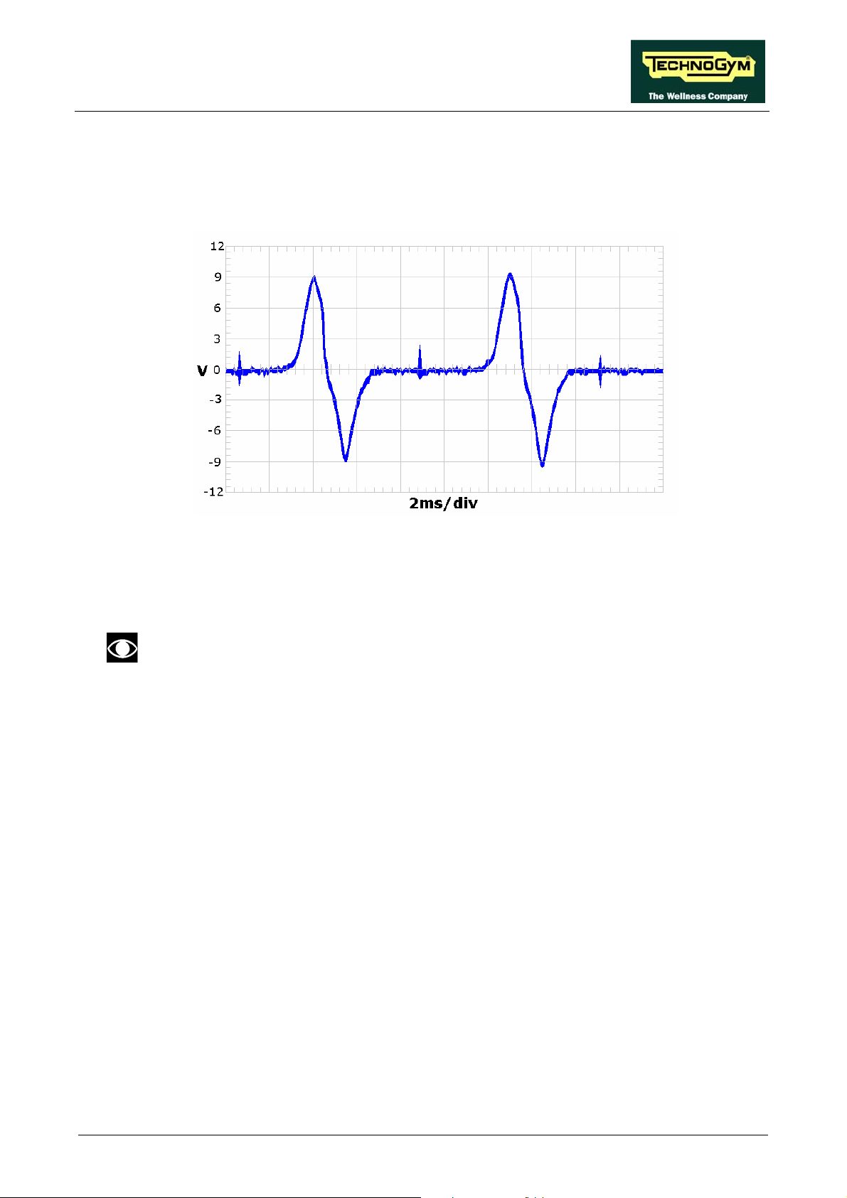
STEP EXCITE: Service & maintenance manual - rev. 1.4
• Pulses
This is the signal produced by the speed sensor, and has the waveform shown in the figure
below:
Figure 3.2-1
The signal enters the brake board (pins 3-4 on connector CN2), where it is used to determine the
speed value that is sent to the display board via the RS-485 serial link.
This signal can also be measured qualitatively using a multimeter. The voltage
measured across the sensor terminals should be 0 Vdc when the machine is stopped,
and should increase to a few hundred mV during pedal movement: the higher the
speed, the higher the measured voltage.
Page 3.13
Page 44

STEP EXCITE: Service & maintenance manual - rev. 1.4
Page intentionally left blank
Page 3.14
Page 45

STEP EXCITE: Service & maintenance manual - rev. 1.4
4. ACCESSORIES
4.1. CARDIO THEATER CONNECTION
The machine can be connected to the CardioTheater by means of the RJ45 connector on the CSafe
board. The CardioTheater unit must be provided with a power cable having the following pin-out:
RJ45 Connector Signal
5 +5 Vdc
7 Ground
ATTENTION: for the numbering of the pins, on RJ45 connector, please refer to the
diagram below:
4.2. PC LINK FOR PROGRAMMING
The machine can be connected to a PC for programming by means of the RJ45 connector on the
CSafe board.
The cable to use (code 0WC00434AB) must be wired as follows:
ATTENTION: for the numbering of the pins, on RJ45 connector, please refer to the
diagram below:
Page 4.1
Page 46

STEP EXCITE: Service & maintenance manual - rev. 1.4
When programming the machine sometimes it is necessary to fit plug into the free RJ-45
port on the back of the display, to avoid any type of interference during the operation.
The wiring diagram of the RJ-45 plug is as follows:
Programming cable and plug can be ordered using the code H0002534AA.
4.3. CABLE FOR EXCHANGING TV CHANNEL TUNING DATA
BETWEEN TWO MACHINES
The link for transferring the TV channel tuning data from one machine to the other is effected via a
special cable, which plugs into the RJ45 connectors of the CSafe boards.
The cable to use (code 0WC00644AA) must be wired as follows:
Cable
CSafe Board;
RJ45
3 Tx White 4
4 Rx Brown 3
7 Digital Ground Green 7
8 Ground Shield Yellow 8
Signal Color CSafe Board;
RJ45
ATTENTION: for the numbering of the pins, on RJ45 connector, please refer to the
diagram below:
Page 4.2
Page 47

STEP EXCITE: Service & maintenance manual - rev. 1.4
4.4. MONITOR PLUG FOR CSAFE PORT
When the plug code 0WC00639AA is fitted into any one of the CSafe ports on the machine, the
corresponding LED should illuminate to indicate the presence of the 5 Vdc supply on the port.
During the CSafe port test function, the plug connects the transmit channel directly to the receive
channel, thereby producing a positive test outcome if the port is functioning correctly.
Page 4.3
Page 48

STEP EXCITE: Service & maintenance manual - rev. 1.4
4.5. WELLNESS TV UPGRADE KIT
There are upgrade kits available for converting Excite machines from the version with traditional
LED display to the version with Wellness TV display. The kit also includes all the cables and
connectors required for the input of the antenna signal. The table below gives the codes of the kits
for each machine.
WELLNESS TV
UPGRADE KIT
STEP 700 A0000169AA-#
Where the character ‘#’ must be replaced with the multistandard code matching the TV standard of
the country where the machine has to be installed:
Multistandard
code
E
U
TG
TV Standard Countries
code
1 PAL B/G
2 PAL I
5 SECAM E/L
6 SECAM D/K
8 PAL D/K
9 SECAM B/G
A SECAM K1
3 PAL N
4 NTSC
7 NTSC M44
B PAL M
Albania Australia Austria Bahrain Belgium
Cameroon Croatia Cyprus Czech Rep Denmark
Finland Germany Ghana Greece Hungary
India Israel Italy Jordan Kenya
Luxembourg Malaysia Malta Netherlands New Zealand
Nigeria Norway Pakistan Poland Portugal
Romania Singapore Slovakia Slovenia Spain
Sri Lanka Sweden Switzerland Thailand Turkey
United Arab E Zambia Zimbabwe
Botswana Hong Kong Ireland South Africa Seychelles
UK
France
Bulgaria Estonia Ex URSS Latvia Lithuania
Poland Russia Ukraine
Czech Rep China Poland
Saudi Arabia Iran Iraq Morocco Tunisia
Syria
French Guyana Guadeloupe Madagascar Martinique New Caledonia
Senegal Togo Zaire
Argentina Paraguay Uruguay
Bahamas Bermuda Canada Chile Costa Rica
Guatemala Japan Korea Peru Philippines
Taiwan Trinidad USA Venezuela
Mexico
Brazil
CODE
Page 4.4
Table 4-1
Page 49

STEP EXCITE: Service & maintenance manual - rev. 1.4
4.5.1. INSTALLATION PROCEDURE
NOTE: It is always advisable, in any case, to upgrade the brake interface board to the
latest SW version.
The upgrade kit consists of:
Figure 4.5-1
(1) External connector board cover plate
(cod. 0C000550AB);
(2) External connector board
(cod. 0WQ00115AC);
(3) Self-tapping screws 5x14 (cod. 0Z775);
(4) Self-tapping screws 3.5x6 (cod. 0Z7018);
(5) Washers (cod. 0Z343);
(6) Connector plate (cod. 0G000353AB);
(7) Union connector (cod. 0K000303AA);
(8) STP_07 cable (cod. 0WCU0008AA);
(9) CB-9 cable (cod. 0WC00447AB);
(10) Code sticker (cod. 0E109);
(11) 12-inch LCD display assembly.
Figure 4.5-2
Page 4.5
Page 50

STEP EXCITE: Service & maintenance manual - rev. 1.4
1. Turn off the machine and unplug the mains
lead from the wall outlet.
2. Back off the 4 screws a using a medium
Phillips screwdriver.
Figure 4.5-3
Figure 4.5-4
3. Unplug the connectors indicated in the
figure.
4. Remove the display.
5. Turn the machine over on one side.
6. Back off the 4 screws b using a Phillips
screwdriver.
7. Remove the cover c.
Page 4.6
Figure 4.5-5
Continued on following page →
Page 51

STEP EXCITE: Service & maintenance manual - rev. 1.4
Figure 4.5-6
8. Remove connector plate d from the front
platform.
Figure 4.5-7
Figure 4.5-8
9. Assemble union connector 7 on connector
plate 6, securing it with its own lock-nut after
inserting the washer, as shown in the figure.
10. Insert cable 8 (STP_07) into hole e, and
bring it out from the top of the machine.
If the cable doesn’t pass trough the
machine frame, use a cable puller.
11. Plug the lower end of cable 8 (STP_07) into
union connector 7, previously assembled on
connector plate 6.
12. Snap connector plate 6 into its seat on the
platform.
13. Turn the machine back upright.
Continued on following page →
Page 4.7
Page 52

STEP EXCITE: Service & maintenance manual - rev. 1.4
14. Remove cover plate f, backing off the 4
screws h using a Phillips screwdriver.
Figure 4.5-9
Figure 4.5-10
15. Insert external connector board 2 along the
special guides on cover plate 1, in such a
way that the connectors on the board match
up with the holes on the cover plate.
16. Secure external connector board 2 with
screws and washers 4 and 5, using a Phillips
screwdriver.
17. Connect cable 9 (CB-9) to connector board
2.
18. Assemble cover plate 1 inside the rear
display housing, using the 4 screws 3 and a
Phillips screwdriver.
Page 4.8
Figure 4.5-11
Continued on following page →
Page 53

STEP EXCITE: Service & maintenance manual - rev. 1.4
Figure 4.5-12
Figure 4.5-13
19. Remove the covering from the LED display,
backing off the 3 screws h using a medium
Phillips screwdriver.
20. Unplug the TGS cable, if present.
21. Assemble the covering removed previously
in step 19 onto the WTV display, and secure
using the 3 screws h.
22. Connect the following cables to the WTV
display:
• Cable 8 (STP_07) on connector j1 of the
connector board.
• All the connectors previously
disconnected from the display in step 3.
• The TGS cable, if present, on connector
CN8 of the CPU board.
23. Fix the new display on the machine using the
4 screws removed previously in step 2.
Figure 4.5-14
24. Affix the sticker 10 in the position indicated
in the figure.
25. Turn on the machine and check that it is
working properly.
26. Carry out the Wellness TV configuration and
tuning procedure.
Page 4.9
Page 54

STEP EXCITE: Service & maintenance manual - rev. 1.4
Page intentionally left blank
Page 4.10
Page 55

STEP EXCITE: Service & maintenance manual - rev. 1.4
5. INSTALLATION INSTRUCTIONS
5.1. SPECIFICATIONS AND REQUIREMENTS
For correct machine installation, make sure that:
1. The machine is installed on a level surface that is free of vibrations and has sufficient carrying
capacity for the combined weight of the machine and user.
2. The place of installation is free of dust and sand.
3. The place of installation meets the operating temperature and humidity conditions specified in
paragraph 2.6. “Ambient specifications”.
4. The m
(television sets, electrical motors, antennas, high voltage lines, household appliances, etc...) or
medical equipment.
5. To eliminate possible interference with the cardio receiver, no transmitters should be placed less
than 1 meter from the display.
Only for 500i, 700i and 700i E models.
6. The mains voltage must match the value specified on the machine rating plate.
7. The electrical system must be correctly earthed.
8. The wall outlet used should be reserved for the machine and have a rating of at least 100 VA.
9. The maximum number of machines connected in cascade should be that indicated in paragraph
3.1.11. “Power entry module”.
10. Position the m
achine is not positioned close to sources of heat, sources of electromagnetic noise
ains lead of the machine where it will not be underfoot.
5.2. INSTALLATION REQUIREMENTS AND SPECIFICATIONS
FOR WELLNESS TV MACHINES
1. Ensure that the specifications and requirements for installation have been met (see paragraph
5.1. “Specifications and requirements”).
2. To obtain a good video signal, the S/N ratio at the antenna signal input of a W
machine should be between 70 and 80 dB.
WARNING: If the machine is not connected to a terrestrial antenna--or if it is but the
antenna line is split by devices such as TV distribution units, modulators, etc.--the machine
will not be able to receive a usable antenna signal for radio channel tuning.
ellness TV
Page 5.1
Page 56

STEP EXCITE: Service & maintenance manual - rev. 1.4
5.3. INSTALLATION
To correctly install the machine, proceed as follows:
1. Ensure that the specifications and requirements for installation have been met (see paragraph
5.1. “Specifications and requirements”).
2. Position the machine as specified above, on a level surface that is free of vibrations and has
sufficient carrying capacity for the combined weight of the machine and user.
3. The machine is shipped fully assembled and packed in a carton fixed to a wooden pallet.
Only for 500i, 700i and 700i E models.
4. Connect the mains lead to the power inlet socket on the machine.
5. Place the on/off switch in the 0 position.
6. Plug the mains lead into the wall outlet.
Only for 700i E model.
7. Connect the antenna cable to the socket.
5.4. FIRST POWER-ON
After completing the installation procedure, the machine is ready for use.
On the 500i, 700i and 700i E models, simply turn the on/off switch from position 0 to position 1,
while on the 500i SP and 700i SP models it is necessary to get on the machine and start pedaling.
On power-up the machine performs a self-test of the upper and lower assemblies. After completing
the self-test, the machine enters the stand by state, awaiting a command from the keyboard.
To check the correct operation of the machine:
• get on the machine;
• start exercising;
• check that the displayed speed varies accordingly;
• check that exercise resistance varies when the “+” and “-“ effort level keys are pressed, or the
touch sensors on the 700i, 700i SP and 700i E models are pressed, and the effort level change
from 1 to 25;
• put on the heart rate meter and check that the machine correctly reads the heart rate value;
• only for 700i, 700i SP and 700i E: grasp the sensors and check that the machine correctly reads
the heart rate value.
• only for 700i E: Carry out the procedure described in paragraph 9.7. “Touch screen calibration”.
Page 5.2
Page 57

STEP EXCITE: Service & maintenance manual - rev. 1.4
6. TROUBLESHOOTING
The troubleshooting procedures are illustrated by means of flow diagrams. To facilitate
interpretation of these diagrams, the following standard box shapes are used:
This type of box is the START point of the troubleshooting procedure. It
typically contains a description of the problem or malfunction.
This type of box represents a decision point in the troubleshooting procedure.
It typically contains a description of the CHECK to be made, with an outcome
that is either a positive (YES) or negative (NO) response.
This type of box is a step in the troubleshooting procedure where an ACTION
must be carried out. It typically contains a description of the ACTION
necessary to resolve the problem Therefore, after executing the specified
ACTION:
1. Check whether the problem has been resolved;
2. If the problem persists, it is recommended to resume the troubleshooting
procedure from the point before the action was carried out.
A circled number (such as that shown on the left) next to a box of the
troubleshooting procedure indicates that more detailed instructions for
performing that particular check or action are provided below the flowchart.
A circled letter (such as that shown on the left) is used to mark a point in the
procedure. Typically, this indicator is used in page changes.
Page 6.1
Page 58

STEP EXCITE: Service & maintenance manual - rev. 1.4
6.1. SERVICE TROUBLESHOOTING MENU
The configuration procedure is invoked when the machine is in standby mode, using a different
procedure for the 500 and 700 models.
• Accessing configuration of 500 models
Simultaneously press the ENTER, ↑, CLEAR keys. The following prompt appears on the LED
display:
ENTER PASSWORD:
To access the procedure, type in the password 2501 which protects against unauthorized access and
press “Enter” to confirm. To enter the password, increase or decrease the displayed value using the
↑ and ↓ keys, or use the +/- GOAL keys to scroll through and modify the individual digits.
At this point there are two options available:
↑ = Tech Config
↓ = Troubleshooting
Press numeric key ↑ to access the menu for configuring technical parameters; the machine display
will begin showing the current configuration, structured as in the diagram below:
• Accessing configuration of 700 models
Simultaneously press the keys 369 for 700 LED models, whereas on 700 Wellness TV models the
keys 0369 must be pressed one after the other. The following prompt appears on the display:
ENTER PASSWORD:
To access the procedure, type in the password 2501 which protects against unauthorized access and
press the “Enter” key to confirm. At this point there are two options available:
1 = Tech Config
2 = Troubleshooting
Press numeric key 1 to access the menu for configuring technical parameters; the machine display
will begin showing the current configuration, structured as in the diagram below:
Page 6.2
Page 59

STEP EXCITE: Service & maintenance manual - rev. 1.4
TROUBLESHOOTING
AUTOMATIC TEST M ANUAL T ES T
I2C Devices Test
LED Test
SERIAL PORT S
TEST
TGS COM Test
Low Kit COM Test
CSafe COM Test
MAN.KEYBOARD
TEST
To scroll through the list of available functions, press the + or – effort level keys to display the next
or the preceding item; confirm the choice by pressing ENTER. To cancel the operation, press the
CLEAR key for a few seconds.
The tests are divided into two groups: Automatic and Manual, and the prompt for a choice appears
immediately on accessing the troubleshooting menu.
6.1.1. AUTOMATIC TEST
The tests grouped under this section conduct checks on the machine’s operation in a fully automatic
manner. After selecting the desired test using the + and – effort level keys, press ENTER to initiate
the test and then await the result. Press ENTER again to continue, and use the CLEAR key to
return to the higher menu level, holding it down for a few seconds. The various tests are described
below.
6.1.1.1. I2C Devices Test
The I2C Devices test checks the com
outcomes:
• “Test Successful, press Enter to continue”: Signifies that the transmission and reception of
data packets between the I2C devices and the display board was completed successfully.
• “EEPROM Error, press Enter to continue”: Signifies that the display board is having
problems communicating with its memories.
6.1.1.2. LED Test (not on 700iE models)
The LED test checks the functioning of the display by lighting all the LEDs in the matrix. It also
tests the buzzer by changing the frequency to produce a variation in the tone of the sound.
munication following the 32K and 256K. The test can have
Page 6.3
Page 60

STEP EXCITE: Service & maintenance manual - rev. 1.4
There is no message displayed concerning the outcome of this test, which must therefore be
checked visually.
6.1.1.3. Serial Ports Test
The serial ports test checks the communications on the following interface ports:
• CSafe COM test;
• Low Kit COM test;
• TGS COM test.
Using the + and – effort level keys, select the desired test item and confirm by pressing ENTER.
The test can have two outcomes:
• “Test Successful, press Enter to continue”: This means that the test was completed
successfully, i.e. that the communications on the selected serial port are functioning correctly.
• “COMx error, press Enter to continue”: This means that the outcome of the test was
negative: the message will specify COM1 in the case of the CSafe COM test, COM2 in the case
of communications with the low kit, or COM3 in the case of the TGS COM test.
The “TGS COM test” done on machine not provided with the key reader gives a fail
outcome. The same if the “CSafe COM test” is done on a machine which CSafe port is
not plugged with the monitor plug described at paragraph 4.4. “Monitor plug for CSafe
port”.
6.1.2. MANUAL TEST
The tests grouped under this section conduct checks on the machine’s operation in a fully automatic
manner. After selecting the desired test using the + and – effort level keys, press ENTER to initiate
the test and then await the result. To exit test mode, press and hold down the CLEAR key for a few
seconds.
6.1.2.1. Man. Keyboard Test
The m
the test by pressing ENTER, the message “Press all buttons (beep=OK)” appears on the display.
Pressing each key will produce an audible signal; if a key does not produce the beep it means it is
not working properly.
On Wellness TV machines, pressing the keys does not produce an audible signal, but if the key is
working correctly it lights up green.
anual keyboard test checks the functioning of all the keys on the keyboard. After accessing
Page 6.4
Page 61

STEP EXCITE: Service & maintenance manual - rev. 1.4
6.2. THE DISPLAY FAILS TO ILLUMINATE
This error occurs when the power supply voltage is not reaching the upper assembly.
6.2.1. 500I AND 700I MODELS
THE DISPLAY
DOES NO T
ILLUMINATE
NO
Does t h e wall out let s upply t he
correct v olt ag e?
Plug the mac hi ne int o a
working elec trical out l et
YES
Is t he m ains lead OK?
YES
Are the f uses OK?
YES
Is the v olt age at t he
output of t he mac hine's
power entry modul e
correct?
NO
Replace t he m ain s lead
NO
Replace the fuses
1
NO
Replace t he power
entry m odul e on the
machine
YES
A
Page 6.5
Page 62

STEP EXCITE: Service & maintenance manual - rev. 1.4
A
2
Replace t he display
board and/or the 386
board
YES
Does t h e m ains v oltage
reach t he input to t he
brake boar d?
YES
Are the DC voltages at t he
output of t he brake board
correct?
YES
Are the D C volt ages at t he
input t o t he dis play board
correct?
NO
Replace c able STP-00
3
NO
Replace the brake
board
4
NO
Replace c able STP-03
Follow the procedure step by step to correctly diagnose the problem. Take particular care with the
checks highlighted by circled numbers, which are described in detail below:
To speed up the troubleshooting procedure, check the state of the power indicator LEDs
on the various circuit boards.
(1) Slightly lift up the fastons on the machine power entry module. Place the tester probes across
the live and neutral pins on the same connector. The measured value should be approximately
220 VAC or 110 VAC depending on the mains voltage.
(2) As for step (1) but across pins 3 and 1 of connector CN3 on the Brake board.
(3) Using a tester, check that all the output voltages on connector CN1 of the brake board are
correct, referring to paragraph 2.8. “Wiring”.
(4) As for step (3) but on connector CN1 of the display board.
Page 6.6
Page 63

STEP EXCITE: Service & maintenance manual - rev. 1.4
6.2.2. 500I SP AND 700I SP MODELS
THE DISPLAY
DOES NO T
ILLUMINATE
Is the us er i s ex ercis i ng?
YES
Is there a v olt ag e at t he
output of the alt ernat or?
YES
Is there a v olt ag e at t he
input t o t he br ak e boar d?
NO
Correct operation: af t er
30 seconds without do
the ex er c ise, t he
machine switches off
1
2
NO
Replace the alt ernat or
3
NO
Replace cable STP-01
or the fuse in the same
cable
Replace t he display
board
YES
YES
Are the D C volt ages at t he
output of t he brake board
correct?
YES
Are the D C volt ages at t he
input t o t he dis play board
correct?
4
NO
Replace the brake
board
5
NO
Replace c able STP-03
Page 6.7
Page 64

STEP EXCITE: Service & maintenance manual - rev. 1.4
Follow the procedure step by step to correctly diagnose the problem. Take particular care with the
checks highlighted by circled numbers, which are described in detail below:
To speed up the troubleshooting procedure, check the state of the power indicator LEDs
on the various circuit boards.
(1) Check if the machine stays on for 30 seconds after having stopped pedalling. If the machine
switches off in few seconds, check if the fuse on the STP-01 cable is blown.
(2) Place the tester probes across the ends of the cable from the alternator. The measured voltage
should be approximately 15-17 VDC at a speed of about 30 SPM.
(3) As for step (1) but across pins 1 and 2 of connector CN3 on the brake board.
(4) Using a tester, check that all the output voltages on connector CN1 of the brake board are
correct, referring to paragraph 2.8. “Wiring”.
(5) As for step (4) but on connector CN1 of the display board.
Page 6.8
Page 65

STEP EXCITE: Service & maintenance manual - rev. 1.4
6.2.3. 700I E MODEL WITH WELLNESS TV
THE DISPLAY
DOES NO T
ILLUMINATE
Does t h e wall out let s upply t he
correct v olt ag e?
YES
Is t he m ains lead OK?
YES
Are the t he f uses OK ?
YES
NO
Plug th e m ac hine i nt o a
working elec trical out l et
NO
Replace the mains lead
NO
Replace t he f us es
1
Is the v olt age at t he
output of t he machine's
power entry modul e
Does the mains voltage
reach t he input to t he
brake board?
Continued on the following page.
correct?
A
YES
YES
NO
Replace t he power
entry module on the
machine
2
NO
Replace c able STP-00
Page 6.9
Page 66

STEP EXCITE: Service & maintenance manual - rev. 1.4
A
3
Are the DC voltages at the
output of t he brak e board
correct?
YES
NO
Replace the brake
board
4
Are the DC
voltages c orre c t at t he:
-input of t he c onn. board?
-input of the C PU bo ard
(UB models )?
YES
Are the D C volt ages at the
output of the C PU board to
the LC D i nv ert er c or rec t?
YES
Are the D C volt ages at the
input t o t he LCD inv ert er
correct?
NO
Replace cable STP-03
5
NO
Replace t he C PU
and/or connec t or
board
6
NO
Replace cable:
-CV-302 ( N C B m odels)
-CU98 (U B m odels )
Are the AC v olt ages at t he
output t o the LCD i nv erter
Continued on the following page.
Page 6.10
YES
7
NO
Replace LC D inv ert er
correct?
B
Page 67

STEP EXCITE: Service & maintenance manual - rev. 1.4
B
NO
Replace the LCD
NO
Is the LC D neon la m p on?
YES
Chec k the c onnect ion or
try t o rep lac e the c able
between CPU board and
TTL board.
It works?
NO
Try t o replace t he C PU
board.
It works?
Replace LC D
YES
Cable dam ag e
YES
CPU board dam ag e
Follow the procedure step by step to correctly diagnose the problem. Take particular care with the
checks highlighted by circled numbers, which are described in detail below:
To speed up the troubleshooting procedure, check the state of the power indicator LEDs
on the various circuit boards.
(1) Place the tester probes across the ends of the cable coming from the generator. The measured
value should be approximately 110 or 220 VAC, depending on the mains voltage.
(2) As for step (1) but across pins 1 and 2 of connector CN3 on the Brake board.
(3) Using a tester, check that all the output voltages on connector CN1 of the brake board are
correct, referring to paragraph 2.8. “Wiring”.
(4) As for step (3) but on connector CN16 of the connector board.
(5) As for step (3) but on connector CN5 of the CPU board.
Page 6.11
Page 68

STEP EXCITE: Service & maintenance manual - rev. 1.4
(6) As for step (3) but on connector CN1 of the LCD inverter.
(7) Place the tester probes across the two pins of connectors CN2 and CN3 on the LCD inverter
board. The measured value should be approximately 380 VAC.
Page 6.12
Page 69

STEP EXCITE: Service & maintenance manual - rev. 1.4
6.3. NO AUDIO SOUND
This error can be due to an incorrect machine configuration, or to problems with the audio circuit.
NO AUDI O SOUND
1
Replace the CPU board
NO
Is the TV st anda rd c or rec tly
conf igured?
YES
Replace t he headph one jack .
Does it work?
NO
Try re plac i ng t he C PU. D oes i t
work?
NO
YES
YES
Correct ly c onf igur e t he
"TV Standard"
parameter
Def ec t i v e headphone
jack
Defect iv e C PU board
Follow the procedure step by step to correctly diagnose the problem. Take particular care with the
checks highlighted by circled numbers, which are described in detail below:
(1) Carry out the configuration procedure described in paragraph 9.3.12. “TV Standard (700i E
version only)”.
Page 6.13
Page 70

STEP EXCITE: Service & maintenance manual - rev. 1.4
6.4. NO TV PICTURE
Check that the machine is connected to an antenna signal
This error can be due to an incorrect machine configuration, or to problems with the antenna signal.
NO TV P ICT URE
1
NO
Is the ant enn a c able properl y
connected t o t he connec tor
board?
Connec t t he c abl e
The signal derived f rom
the v ideo signal is
insuf fi c ient . C ont ac t t he
sy stem adm i nis trator
NO
YES
Is the TV standard c orrec tly
conf igured?
YES
Dis c onnec t the s plitt er and
connect t he t uner direct ly t o an
antenna cable. D oes it work?
NO
Try re plac i ng t he C PU.
Does it work?
2
NO
Correct ly c onf igur e t he
"TV Standard"
parameter
3
YES
Replace t he s pl itt er
YES
Defective CPU board
Follow the procedure step by step to correctly diagnose the problem. Take particular care with the
checks highlighted by circled numbers, which are described in detail below:
(1) Check that the antenna cable is correctly connected to connector J1 on the connector board.
Page 6.14
Page 71

STEP EXCITE: Service & maintenance manual - rev. 1.4
(2) Carry out the configuration procedure described in paragraph 9.3.12. “TV Standard (700i E
version only)”.
(3) For models with European electronics, unplug the antenna cable from the connector board
and plug it into the tuner; while for models with US electronics, plug the external antenna
cable into the tuner.
Page 6.15
Page 72

STEP EXCITE: Service & maintenance manual - rev. 1.4
6.5. THE RADIO DOES NOT PLAY
The radio signal can only be acquired from an analog antenna signal. If the machine is
connected to a digital source it will be impossible to use the radio function.
This error can be due to an incorrect machine configuration, or to problems with the antenna signal.
THE RADIO DO ES NOT
PLAY
Is the antenna input connected
to a t e rres trial ant e nna c able
without any ty pe of interruption
(multiplexer, TV dist r ibution
module)?
YES
Is the TV channel sound OK?
YES
Dis c onnect t he s plit t er and
connect t he t uner direct ly t o an
antenna cable. D oes it work?
NO
Connect a s ignal t hat
meet s thes e
requirements
NO
Perform the "Audio do es
not work" procedure
1
YES
Replace t he s pl itt er
NO
The signal derived f rom
the v ideo signal is
insuf f ic ie nt . C o nt ac t t he
sy stem adm i nis trator
NO
Try repl ac i ng the C PU .
Does it work?
YES
Defective CPU board
Follow the procedure step by step to correctly diagnose the problem. Take particular care with the
checks highlighted by circled numbers, which are described in detail below:
Page 6.16
Page 73

STEP EXCITE: Service & maintenance manual - rev. 1.4
(1) After disconnecting the splitter from the tuner, procure a female RC connector and a copper
wire about 1.5 m long. Connect the copper wire to the tuner through the RC connector, so that
it serves as an antenna.
Page 6.17
Page 74

STEP EXCITE: Service & maintenance manual - rev. 1.4
6.6. “THE EQUIPMENT IS BLOCKED” MESSAGE ON DISPLAY
This error message can be caused by:
• loss of communication between the lower and upper assemblies;
• the brake board has detected an error condition, causing it to generate an alarm and store the
error code in memory.
"THE EQUIPMENT IS BL O C KED"
MESSAGE ON THE D ISPL A Y
Carry out the "Error
detected by brake
board" t roubl es ho ot i ng
procedure
3
YES
Is the serial
comm unic at ion bet ween
display and lower
elect ronic correct?
1
NO
Reins tat e the
communication link
between the upper and
lower assem blies
2
Follow the procedure step by step to correctly diagnose the problem. Take particular care with the
checks highlighted by circled numbers, which are described in detail below:
(1) Use the serial communications test described in paragraph 6.1.1.3 “Serial Ports Test”.
(2) To reinstate communications between the lower and upper assemblies:
• check that cable STP-04 is correct using the Test Box Excite;
• try replacing the brake board and the display board in turn, and check whether the
communication works.
(3) Check whether the brake interface board is in an error condition, by accessing the “Low kit
fault code” function in the “Low kit menu” described in paragraph 9.3.6.2 “Low Kit fault
code”.
If the displayed parameter value is “0”, there is no error condition.
Page 6.18
Page 75

STEP EXCITE: Service & maintenance manual - rev. 1.4
6.7. ERROR DETECTED BY BRAKE BOARD
When the brake board detects an error, it stops and interrupts the power supply to the brake
winding, writes a code identifying the fault condition to the error history log and sends an error
status signal to the display board. When this error signal is received by the display board, it
interrupts the exercise and shows the “THE EQUIPMENT IS BLOCKED” message on the display.
The errors logged by the brake board can also be viewed from the machine keyboard as described
in paragraph 9.3.4. “Errors log” or in paragraph 9.3.6.2 “Low Kit fault code”.
ERROR DETECTED BY
BRAKE BOA RD
Error 1
Check the error code
stored in memory
Error 8
The following paragraphs describe the troubleshooting procedures for these cases.
6.7.1. BRAKE BOARD ERROR 1
This code indicates an overheating error: this condition occurs when the temperature detected by
the sensor on the circuit board exceeds 90°C.
Try switching the machine off for 1 hour. If it resumes working correctly, the machine probably
overheated as a result of intensive use. If, on the other hand, the error persists, it is necessary to
replace the Brake board.
6.7.2. BRAKE BOARD ERROR 8
This code indicates an overvoltage error: this condition occurs when the +12 Vdc voltage exceeds
13.7 Vdc.
This error is caused by surges in the voltage output by the power supply section of the Brake board,
as a result of defective components. If the error persists or recurs frequently, replace the Brake
board.
Page 6.19
Page 76

6.8. THERE IS NO RESISTANCE
The machine will not produce resistance if:
• the display board is not receiving a speed signal;
• the brake board is not generating current;
• the brake is defective.
TH ER E IS N O
RESISTANCE
STEP EXCITE: Service & maintenance manual - rev. 1.4
Replace c able ELT-02
NO
Are the Watt and SPM values
shown on t he di s pl ay dif f erent
from zero?
YES
Does the brake board supply
curre nt t o the brake winding?
YES
Does t h e brak e winding receiv e
current f rom the brake board?
NO
1
NO
2
YES
Carry out the "SPM value
is incorrect "
troubles hoot ing proc edure
Replace the brake board
Replace the brake winding
Follow the procedure step by step to correctly diagnose the problem. Take particular care with the
checks highlighted by circled numbers, which are described in detail below:
(1) Disconnect the brake winding and measure the current output by the brake board with a load
of at least 5 Ohm and 80 Watts. The value should be different from 0 A.
(2) As for step (1) but with everything reconnected, and across the brake winding.
Page 6.20
Page 77

STEP EXCITE: Service & maintenance manual - rev. 1.4
6.9. THE RESISTANCE IS INCORRECT
The machine will produce an incorrect resistance if:
• the mechanical components are not in perfect condition;
• the speed measurement is incorrect;
• the brake board is defective;
• the brake is defective.
THE
RESIST ANCE IS
INCORRECT
1
NO
2
NO
Repair t he f ault y
mechanical part s
Replace the brake board
Replace the brake winding
YES
Are the m echanics of t he
machine in good condition?
YES
Carry out the "Speed is
Inc orrec t " t roubles hoot ing
procedure
Does t h e brak e boar d out p ut
the current to t he br ak e
winding?
Follow the procedure step by step to correctly diagnose the problem. Take particular care with the
checks highlighted by circled numbers, which are described in detail below:
(1) Check that the mechanical system, consisting of the pedals, belt and brake, moves smoothly
and without higher than normal friction or resistance.
(2) Measure the voltage supplied by the brake interface board to the winding. In QUICK START
mode, select the effort level and check that the value is different from 0.
Page 6.21
Page 78

STEP EXCITE: Service & maintenance manual - rev. 1.4
6.10. THE SPEED SIGNAL IS INCORRECT
The speed signal is incorrect if:
• The brake disk is incorrectly fixed to the flywheel;
• The speed sensor is defective;
• The brake board is defective.
TH E SPEED IS
INCORRECT
1
Is the brake dis k c orrec tly fixed
to t h e f ly wheel?
YES
Does t h e s peed s ensor s e nd
the c or rec t s igna l t o the brak e
board?
YES
Check if t he parameters
conf iguration i s r igh t . I s the
speed signal c or rect ?
NO
Fix it correctly
2
NO
Replace the
speed sens or / generat or
3
YES
Configuration param et er
not c orrec t
YES
4
SW not c orr ec t l y loaded
YES
Upload t he brak e board SW. I s
the s pee d s ignal c orr ec t ?
NO
Replace the brake board
Follow the procedure step by step to correctly diagnose the problem. Take particular care with the
checks highlighted by circled numbers, which are described in detail below:
Page 6.22
Page 79

STEP EXCITE: Service & maintenance manual - rev. 1.4
(1) Check that the 6 screws fixing the disk brake to the flywheel are all locked down.
The speed sensor detects the heads of these screws.
(2) Powered models: Place the tester probes across the terminals of the speed sensor. The
measured signal should be that indicated in Figure 3.2-1. In addition, when
pedaling at 80 SPM the frequency of the signal should be 136 Hz.
Self-Powered models: Check the signal on the STP-01 cable referring to paragraph 2.8.
“Wiring”. The measured signal should be that indicated in Figure
3.2-1. In addition, when pedaling at 80 SPM the frequency of the
signal should be 136 Hz.
The speed signal can also be observed qualitatively, using a multimeter. The value
should be 0 Vdc when the machine is stopped, and gradually increase as the speed
increases.
(3) Launch the default setting for the low kit parameters.
(4) Update the low kit SW uploading both firmware and brake table. At the end launch the
default setting for the low kit parameters.
Page 6.23
Page 80

STEP EXCITE: Service & maintenance manual - rev. 1.4
6.11. THE MACHINE DOES NOT READ THE TGS
The machine displays this error if the TGS reader is not working properly, or if it is not supplied by
the display board.
TH E MA CH INE DOES
NOT READ THE TGS
1
Replace the dis play board
NO
Does t he s upply voltage
correct ly reach t he inp ut to t he
TGS reader?
NO
Is the s upply v olt age correct at
the output to t he display board
correct?
A
Is the serial c om m unic ation link
between the display board and
the TGS reader OK?
YES
A
2
YES
Replace c able C B Q-32
3
YES
Replace the TGS reader
NO
3
YES
TGS reader defec tiv e
Replace the dis play board
NO
Replace t he TGS reader. I s t he
comm unic at ion li nk bet ween the
displ ay board and t he TGS
reader OK?
Follow the procedure step by step to correctly diagnose the problem. Take particular care with the
checks highlighted by circled numbers, which are described in detail below:
Page 6.24
Page 81

STEP EXCITE: Service & maintenance manual - rev. 1.4
(1) Place the tester probes across pins 1 and 3 of connector CN1 of the TGS reader. The
measured value should be +12 Vdc.
(2) As for step (1) but across pins 1 and 9 of connector CN7 on the display board.
(3) Use the serial communications test described in paragraph 6.1.1.3 “Serial Ports Test”.
Page 6.25
Page 82

STEP EXCITE: Service & maintenance manual - rev. 1.4
6.12. THERE IS NO HEART SIGNAL
6.12.1. HFU TELEMETRIC RECEIVER
The machine displays this error if:
1. electromagnetic noise saturate the HR receiver which does not display any value due to a
specific SW filter which cut every signal, greater than 220 bpm;
2. the receiver is not working properly;
3. the receiver is not supplied by the display board.
TH ER E IS N O HR
SIGNAL
1
Carry out the
troubl es hoo t ing pr oc edur e
"THE TELEMETRIC
SIGN AL I S IN C OR R EC T"
2
YES
Replace the rec eiv er
3
YES
Replace C BQ-28 c abl e
Replace display board
Is the supply voltage c orrect at
the inp ut t o the receiv er?
NO
NO
Is the supply voltage c orrect at
the output of t he di s pl ay board?
Follow the procedure step by step to correctly diagnose the problem. Take particular care with the
checks highlighted by circled numbers, which are described in detail below:
(1) Carry out the troubleshooting procedure 6.13. “The telemetric heart rate signal is incorrect”.
(2) Place the tester probes across pins 1 and 3 of connector CN1 of the receiver. The measured
value should be +5 Vdc.
(3) As for step (1) but across pins 1 and 8 of connector CN3 on the display board.
Page 6.26
Page 83

STEP EXCITE: Service & maintenance manual - rev. 1.4
6.12.2. HAND SENSOR
The machine displays this error if the HS interface board is not working, or if it is not supplied by
the display board.
For an easier and quicker diagnosis of the problem, we recommend to use the
functions of Test Box Excite.
TH ER E IS N O HR
SIGNAL
1
Chec k the earth c onnect ion
of t h e m ac hin e
Replace the dis play board
NO
Are the sens ors c orrect ly
connected to the HS interface
board?
YES
Is the s upply v olt age correct at
the input to the HS interface
board?
NO
Is the s upply v olt age correct at
the out put of the dis play board?
2
NO
Reinstat e the connec tion
3
YES
Replace the HS interf ace
board
4
YES
Replace cable CBQ-25-1
Follow the procedure step by step to correctly diagnose the problem. Take particular care with the
checks highlighted by circled numbers, which are described in detail below:
(1) Check the earthing of the machine using a tester to measure the resistance between the ground
pin on the power supply cable and the ground node to which the receiver is connected inside
the display. The value must be less than 1 Ohm.
Page 6.27
Page 84

STEP EXCITE: Service & maintenance manual - rev. 1.4
(2) Check the connections, referring to paragraph 2.8. “Wiring”.
(3) Place the tester probes across pins 2 and 1 of connector J3 on the HS interface board. The
measured value should be +5 Vdc.
(4) As for step (2) but across pins 1 and 6 of connector CN4 on the display board.
Page 6.28
Page 85

STEP EXCITE: Service & maintenance manual - rev. 1.4
6.13. THE TELEMETRIC HEART RATE SIGNAL IS INCORRECT
The machine displays this error if the receiver is disturbed by sources of electromagnetic noise.
THE TELEMETRIC
HR SIG N AL IS
INCORRECT
1
Check t he eart h c onnec tion
of the mac hine
2
Are the m achines c orrect l y
spac ed by t he r equir ed m inim u m
distance?
YES
Is the receiver correctly
positioned an d are t he
connect ing c ab les proper ly
routed?
YES
Are there s ourc es of
electrom agn et ic nois e near t he
receiv er?
NO
Reposition t he mac hines
so t hey are adequately
spaced
3
NO
Correct t he po s ition of t he
receiv er and the rout ing of
the c abl es
4
YES
Move the mac hi ne away
fr om t he noi s e s our c e or
att enuat e the power of t he
noise
Continued on the following page.
NO
A
Page 6.29
Page 86

STEP EXCITE: Service & maintenance manual - rev. 1.4
A
5
NO
Is the t ransm it ter in good
working order?
YES
Us e a c orr ec t l y
func tioni ng t ransm itt er
Replac e the rec ei v er
YES
Is the transmitter always within
the 80 cm range from t he rec eiv er
NO
Reposition the transmitter
within range
Follow the procedure step by step to correctly diagnose the problem. Take particular care with the
checks highlighted by circled numbers, which are described in detail below:
(1) Check the earthing of the machine using a tester to measure the resistance between the ground
pin on the power supply cable and the ground node to which the receiver is connected inside
the display. The value must be less than 1 Ohm.
(2) For machine positioning layouts, use the following diagram as a reference.
89
60
99
78
99
77
102
70
Receiver
115
86
103
83
95
76
103
82
where:
1. The distances are in centimeters.
2. The smaller number indicates the maximum locking distance for signal reception at the
start of the exercise.
3. The higher number indicates the maximum reception distance during the exercise.
Page 6.30
Page 87

STEP EXCITE: Service & maintenance manual - rev. 1.4
r
(3) Check that the cardio receiver has been assembled properly as described in the procedure 7.4.
“Disassembling the cardio receiver”.
(4) To check for electromagnetic noise near the machine, use Test Box Excite as detailed here
below. You can use one of the following cables ELT-16 (0WC00518AB), CBQ-28
(0WC00390AC) or TRM-28 (0WC00336AC) as connection cable.
HFU
Receiver
Connection
cable
HR receive
TEST BOX
EXCITE
The circuit lights the LED for each heart beat and/or disturbance received: in this way it is
possible to determine whether there is any interference, and identify its sources.
(5) Check the battery power level, using a tester if possible. Otherwise use a receiver or another
reference machine to check the operation up to a distance of about 80 cm from the receiver.
Page 6.31
Page 88

STEP EXCITE: Service & maintenance manual - rev. 1.4
Page intentionally left blank
Page 6.32
Page 89

STEP EXCITE: Service & maintenance manual - rev. 1.4
7. DISASSEMBLY OF COMPONENTS
7.1. DISASSEMBLING THE DISPLAY
7.1.1. 700I AND 700I SP LED VERSION
1. Turn off the machine and unplug the mains
lead from the wall outlet.
2. Back off the 4 screws a using a medium
Phillips screwdriver.
Figure 7.1-1
Figure 7.1-2
3. Unplug the connectors indicated in the figure
at left.
4. Remove the display.
5. Back off the 2 screws b, using an 8-mm hex
wrench, to remove the rear display support.
To reassemble the display, carry out the above
steps in reverse order.
Figure 7.1-3
Page 7.1
Page 90

STEP EXCITE: Service & maintenance manual - rev. 1.4
7.1.2. 700I E WELLNESS TV TOUCH SCREEN VERSION
1. Turn off the machine and unplug the mains
lead from the wall outlet.
2. Back off the 4 screws a using a medium
Phillips screwdriver.
Figure 7.1-4
Figure 7.1-5
3. Unplug the cables indicated in the figure
from the connector board and the CSafe
board.
4. Remove the display.
5. Back off the 2 screws b, using an 8-mm hex
wrench, to remove the rear display support.
To reassemble the display, carry out the above
steps in reverse order.
Page 7.2
Figure 7.1-6
Page 91

STEP EXCITE: Service & maintenance manual - rev. 1.4
7.1.3. 500I AND 500I SP VERSION
Figure 7.1-7
1. Turn off the machine and unplug the mains
lead from the wall outlet.
2. Back off the 4 screws a using a medium
Phillips screwdriver.
Figure 7.1-8
Figure 7.1-9
3. Unplug the connectors indicated in the figure
at left.
4. Remove the display.
5. Back off the 2 screws b, using an 8-mm hex
wrench, to remove the rear display support.
To reassemble the display, carry out the above
steps in reverse order.
Page 7.3
Page 92

STEP EXCITE: Service & maintenance manual - rev. 1.4
7.2. DISASSEMBLING THE CIRCUIT BOARDS FROM THE
DISPLAY
7.2.1. 700I AND 700I SP LED VERSION
Carry out the procedure described in paragraph
7.1. “Disassembling the display”.
Then place the display on a work bench. It is
now possible to disassemble its three circuit
boards:
• The 386 board a;
• The display board b;
• The CSafe board c.
Figure 7.2-1
Figure 7.2-2
386 board a:
1. Remove the hot glue and release the fixing
tabs. The board will lift up slightly.
2. Extract it from the connector on the display
board.
display board b:
1. Unplug the keyboard connector indicated in
the figure.
2. Back off the 5 screws d using a medium
Phillips screwdriver.
3. Remove the circuit board.
CSafe board c:
1. Unplug the connector indicated in the figure.
2. Remove the circuit board from the top.
Page 7.4
Figure 7.2-3
Continued on following page →
Page 93

STEP EXCITE: Service & maintenance manual - rev. 1.4
Figure 7.2-4
To remove the hand sensor board:
1. Unplug the 2 connectors indicated in the
figure.
2. Release the 3 clips e and remove the hand
sensor board.
To reassemble the electronics boards, carry out
the above steps in reverse order.
Page 7.5
Page 94

STEP EXCITE: Service & maintenance manual - rev. 1.4
7.2.2. 700I E WELLNESS TV TOUCH SCREEN VERSION
7.2.2.1. NCB models
Carry out the procedure described in paragraph
7.1. “Disassembling the display”.
Then place the display on a work bench. It is
now possible to disassemble its circuit boards:
• The CSafe board a.
• The LCD inverter b;
• The connector board c;
• The CPU board d;
• The Touch Screen interface board e.
Figure 7.2-5
Figure 7.2-6
CSafe Board a:
1. Unplug connector f from the CSafe board.
2. Remove the circuit board from the top.
LCD inverter b:
1. Back off the two screws g using a Phillips
screwdriver.
2. Raise the inverter cover plate.
Page 7.6
Figure 7.2-7
Continued on following page →
Page 95

STEP EXCITE: Service & maintenance manual - rev. 1.4
Figure 7.2-8
1. Unplug the connectors indicated in the
figure.
2. Back off the two screws h securing the board
to the plate of the display.
3. Remove the LCD inverter.
Figure 7.2-9
Figure 7.2-10
Connector board c:
1. Unplug connectors i and l.
2. Back off the screws m using a medium
Phillips screwdriver.
3. Remove the circuit board from the display,
taking care not to damage the connector that
attaches it to the CPU board.
CPU Board d:
1. Disassemble the connector board.
2. Unplug the cables indicated in the figure,
coming from the TTL board, LCD inverter,
touch screen and headphone jack.
3. To unplug the cable from the TTL board,
open the connector on the CPU as shown in
the close-up at the top left, and remove the
cable.
4. Back off the 5 screws n using a small
Phillips screwdriver.
5. Remove the CPU board.
Continued on following page →
Page 7.7
Page 96

STEP EXCITE: Service & maintenance manual - rev. 1.4
Touch screen interface board e:
1. Unplug the cables on connectors CN1 and
CN5, indicated in the figure, coming from
the touch screen and CPU respectively.
2. Back off the screws o using a small Phillips
screwdriver.
3. Remove the circuit board from the display.
Figure 7.2-11
Figure 7.2-12
To disassemble the LCD:
1. Unplug the connectors of the cables leading
from the touch screen to the touch screen
interface board, to the TTL board and to the
LCD (on the inverter) indicated in the figure.
2. Back off the 6 screws p securing the plate
and all the display boards to the front cover.
3. To unplug the cable from the TTL board,
open the connector on the CPU as illustrated
in the close-up at left, and remove the cable.
4. Back off the 2 screws q securing the
headphone jack to the display, using a small
Phillips screwdriver.
5. Unplug the connectors indicated in the
figure.
6. Remove the two headphone jacks from the
display housing.
7. Lift up the plate to which all the circuit
boards and the LCD are fixed.
Page 7.8
Figure 7.2-13
Continued on page 7.11 →
Page 97

STEP EXCITE: Service & maintenance manual - rev. 1.4
7.2.2.2. UB models
Figure 7.2-14
Carry out the procedure described in paragraph
7.1. “Disassembling the display”.
Then place the display on a work bench. It is
now possible to disassem
ble its circuit boards:
• The LCD inverter a;
• The CPU board b.
Figure 7.2-15
LCD inverter b:
1. Back off the two screws c using a Phillips
screwdriver.
2. Raise the inverter cover plate.
3. Unplug the connectors indicated in the
figure.
4. Back off the two screws d securing the board
to the plate of the display.
5. Remove the LCD inverter.
Figure 7.2-16
Continued on following page →
Page 7.9
Page 98

STEP EXCITE: Service & maintenance manual - rev. 1.4
CPU Board b:
1. Disassemble the connector board.
2. Unplug the cables indicated in the figure,
coming from the TTL board, LCD inverter
and headphone jack.
To unplug the cable from the TTL
board, open the connector on the CPU
as shown in the close-up at the top left,
and remove the cable.
3. Back off the 5 screws n using a small
Figure 7.2-17
Phillips screwdriver.
4. Remove the CPU board.
To disassemble the LCD:
1. Unplug the connectors of the cables leading
from the touch screen, to the TTL board and
to the LCD (on the inverter) indicated in the
figure.
Figure 7.2-18
Figure 7.2-19
To unplug the cable from the TTL
board, open the connector on the CPU
as shown in the close-up at left and
remove the cable.
2. Back off the 5 screws f securing the plate and
all the display boards to the front cover.
3. Back off the screws g securing the
headphone jack to the display, using a small
Phillips screwdriver.
4. Unplug the connectors indicated in the
figure.
5. Remove the two headphone jacks from the
display housing.
6. Lift up the plate to which all the circuit
boards and the LCD are fixed.
Continued on following page →
Page 7.10
Page 99

STEP EXCITE: Service & maintenance manual - rev. 1.4
Figure 7.2-20
7. Back off the 10 screws r using a small
Phillips screwdriver.
8. Remove the touch screen protection plate.
9. Shift on one side, the touch screen s paying
attention to its cable.
10. Back off the 4 screws t using a small Phillips
screwdriver.
11. Lift up and remove the LCD.
Figure 7.2-21
To disassemble the AUX input board:
1. Work on the rear display support.
2. Back off the 2 screws s using a small Phillips
screwdriver.
3. Remove the board from its housing.
Figure 7.2-22
Continued on following page →
Page 7.11
Page 100

STEP EXCITE: Service & maintenance manual - rev. 1.4
To remove the hand sensor board:
1. Unplug the 2 connectors indicated in the
figure.
2. Release the 3 clips t and remove the hand
sensor board.
To reassemble the circuit boards and the LCD,
carry out the above steps in reverse order.
Figure 7.2-23
Page 7.12
 Loading...