

Page 1
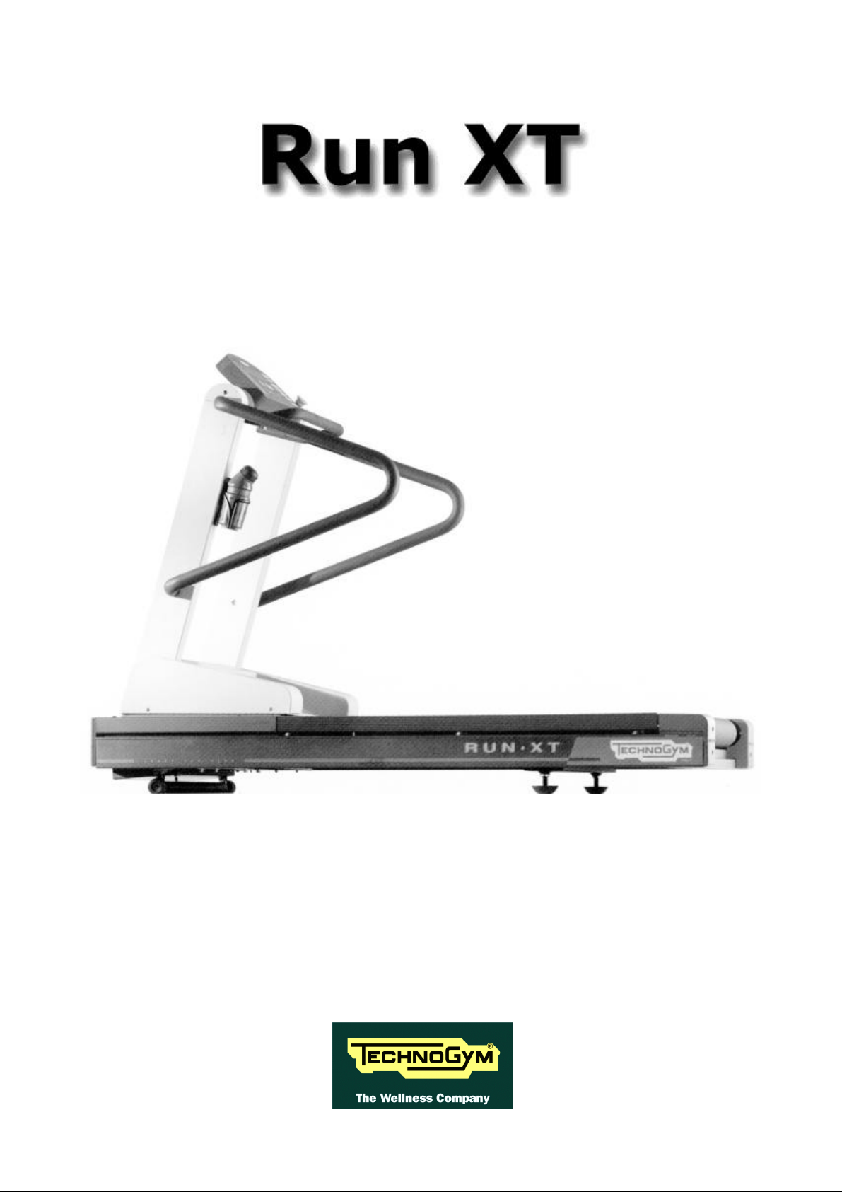
SERVICE & MAINTENANCE MANUAL
PRELIMINARY
Page 2

Page 3
The information contained in this manual is intended for QUALIFIED TECHNICIANS who have
completed a specific TECHNOGYM training course and are authorized to perform machine start-up
and adjustment procedures as well as extraordinary maintenance or repairs which require a thorough
knowledge of the machine, its operation, its safety devices and working procedures.
CAREFULLY READ THE INFORMATION CONTAINED IN
THIS MANUAL BEFORE PERFORMING ANY MAINTENANCE
PROCEDURES ON THE MACHINE
DANGEROUS VOLTAGES
PRESENT EVEN WHEN THE
MACHINE IS TURNED OFF
NOTE
The information contained in this document is subject to change without notice.
Technogym does not guarantee this documentation in any way. Technogym shall not be held
responsible for any errors contained in this manual and declines all liability for accidents or damages
resulting from the supply, characteristics or use of this manual.
This document contains proprietary information that is protected by copyright. All rights reserved.
No part of this document may be photocopied, reproduced or translated into another language
without the prior written consent of Technogym.
The Technogym™ trademark is property of Technogym S.r.l.
The Run XT™ trademark is property of Technogym S.r.l.
Page 4

Page 5

RUN XT: Service & Maintenance Manual - rev. 2.0
Contents
1. GENERAL NOTICES....................................................................................................................................... 1.1
1.1. INTRODUCTION ............................................................................................................................................1.1
1.2. RECOMMENDATIONS.....................................................................................................................................1.1
1.3. GENERAL RULES FOR REPAIR PROCEDURES.....................................................................................................1.2
2. TECHNICAL CHARACTERISTICS...............................................................................................................2.1
2.1. MECHANICAL CHARACTERISTICS...................................................................................................................2.1
2.2. ELECTRICAL CHARACTERISTICS.....................................................................................................................2.1
2.3. AMBIENT SPECIFICATIONS.............................................................................................................................2.1
2.4. CONFORMITY TO REGULATIONS .....................................................................................................................2.1
2.5. WIRING DIAGRAM FOR THE 220 MODEL........................................................................................................ 2.2
2.5.1. Connectors.......................................................................................................................................2.2
2.5.2. Wiring..............................................................................................................................................2.3
2.6. WIRING DIAGRAM FOR THE 220 USA MODEL.................................................................................................2.6
2.7. WIRING DIAGRAM FOR THE 110 MODEL........................................................................................................ 2.8
3. PRINCIPLES OF OPERATION ......................................................................................................................3.1
3.1. BLOCK DIAGRAM..........................................................................................................................................3.1
3.2. TREAD-BELT MOTOR DRIVE...........................................................................................................................3.4
3.3. U P-DOWN MOTOR DRIVE...............................................................................................................................3.6
4. ACCESSORIES.................................................................................................................................................4.1
4.1. CONNECTING TO THE TGS.............................................................................................................................4.1
5. INSTALLATION INSTRUCTIONS................................................................................................................. 5.1
5.1. SPECIFICATIONS AND REQUIREMENTS............................................................................................................5.1
5.2. INSTALLATION .............................................................................................................................................5.1
5.3. FIRST POWER-ON..........................................................................................................................................5.2
6. TROUBLESHOOTING....................................................................................................................................6.1
6.1. THE DISPLAY DOES NOT ILLUMINATE............................................................................................................. 6.2
6.2. THE DISPLAY SHOWS “E1” OR “E2”...............................................................................................................6.6
6.3. THE DISPLAY SHOWS “E3” OR “E4”...............................................................................................................6.8
6.3.1. The inverter display shows E1, E2, E3, E4 or E5.............................................................................. 6.9
6.3.2. The inverter display shows E6 or E7...............................................................................................6.11
6.3.3. The inverter display shows E8, E10 or E11.....................................................................................6.12
6.3.4. The inverter display shows E9 ........................................................................................................6.14
6.3.5. The inverter display shows E12 ...................................................................................................... 6.16
6.3.6. The inverter display shows E14 ...................................................................................................... 6.17
6.3.7. The inverter display does not show any error..................................................................................6.18
6.4. THE BELT MOTOR IS JERKING.......................................................................................................................6.20
6.5. THE BELT MOTOR STARTS WITH DELAY........................................................................................................6.21
6.6. THE DISPLAYED SPEED IS INCORRECT...........................................................................................................6.23
6.7. THE DISPLAY SHOWS “E5”..........................................................................................................................6.26
6.8. THE UP-DOWN MOVES IN ONLY ONE DIRECTION............................................................................................ 6.31
6.9. THE DISPLAYED ELEVATION IS INCORRECT...................................................................................................6.34
6.10.THERE IS NO HEART RATE SIGNAL................................................................................................................6.35
6.11.THE HEART RATE SIGNAL IS INCORRECT ....................................................................................................... 6.36
7. DISASSEMBLY OF COMPONENTS..............................................................................................................7.1
7.1. DISASSEMBLING THE DISPLAY.......................................................................................................................7.1
Page i
Page 6

RUN XT: Service & Maintenance Manual - rev. 2.0
7.2. DISASSEMBLING THE EPROM .........................................................................................................................7.2
7.3. DISASSEMBLING THE CPU BOARD................................................................................................................... 7.3
7.4. DISASSEMBLING THE KEYBOARD...................................................................................................................7.4
7.5. DISASSEMBLING THE CARDIO RECEIVER.........................................................................................................7.5
7.6. DISASSEMBLING THE EMERGENCY BUTTON.................................................................................................... 7.8
7.7. DISASSEMBLING THE MOTOR GUARD............................................................................................................7.10
7.8. DISASSEMBLING THE FRONT PLATE.............................................................................................................. 7.11
7.9. DISASSEMBLING THE RUNNING TRACK......................................................................................................... 7.12
7.10.DISASSEMBLING THE DRIVEN ROLLER, THE DRIVING ROLLER, THE TREAD BELT AND THE MOTOR BELT............7.14
7.11.DISASSEMBLING THE BELT MOTOR...............................................................................................................7.17
7.12.DISASSEMBLING THE ELECTRONIC CIRCUIT BOARDS ..................................................................................... 7.19
7.13.DISASSEMBLING THE INVERTER...................................................................................................................7.20
7.14.DISASSEMBLING THE UP-DOWN MOTOR BELT ...............................................................................................7.21
7.15.DISASSEMBLING THE UP-DOWN MOTOR........................................................................................................ 7.22
7.16.DISASSEMBLING THE UP-DOWN MOTOR BRUSHES..........................................................................................7.25
7.17.DISASSEMBLING THE ELEVATION BARS ........................................................................................................ 7.26
7.18.DISASSEMBLING THE LEAD SCREW NUTS ......................................................................................................7.27
7.19.DISASSEMBLING THE LIMIT SWITCHES..........................................................................................................7.29
7.20.DISASSEMBLING THE PHOTOCELL ................................................................................................................7.30
8. ADJUSTMENTS............................................................................................................................................... 8.1
8.1. TENSIONING A NEW TREAD BELT .................................................................................................................. 8.1
8.2. TENSIONING A USED TREAD BELT ..................................................................................................................8.2
8.3. CENTERING THE TREAD BELT........................................................................................................................8.3
8.4. ADJUSTING THE TENSION AND ALIGNMENT OF THE TREAD-BELT MOTOR BELT ................................................. 8.4
8.5. TENSIONING THE U P-DOWN MOTOR BELT.......................................................................................................8.6
8.6. ALIGNING THE ELEVATION BARS ................................................................................................................... 8.7
8.7. CALIBRATING THE TREAD BELT SPEED...........................................................................................................8.8
8.8. CENTERING THE PHOTOCELL.........................................................................................................................8.9
9. MACHINE CONFIGURATION.......................................................................................................................9.1
9.1. CHANGING THE SETTINGS ON THE DISPLAY PANEL..........................................................................................9.1
9.1.1. Language used .................................................................................................................................9.1
9.1.2. Measurement system......................................................................................................................... 9.1
9.1.3. Maximum time.................................................................................................................................. 9.2
9.1.4. Activating the “+” and “−” keys......................................................................................................9.2
9.1.5. Disabling the function keys...............................................................................................................9.2
9.1.6. Enabling the “ENTER” key ..............................................................................................................9.2
9.2. MAINTENANCE INFORMATION....................................................................................................................... 9.3
9.2.1. Hours on ..........................................................................................................................................9.3
9.2.2. Hours of use ..................................................................................................................................... 9.3
9.2.3. Hours of motor use...........................................................................................................................9.3
9.2.4. Minutes of up-down motor use..........................................................................................................9.3
9.2.5. Distance travelled ............................................................................................................................9.3
9.3. CHANGING THE MAINTENANCE INFORMATION................................................................................................9.3
9.3.1. Hours on ..........................................................................................................................................9.3
9.3.2. Hours of use ..................................................................................................................................... 9.4
9.3.3. Hours of motor use...........................................................................................................................9.4
9.3.4. Minutes of up-down motor use..........................................................................................................9.4
9.3.5. Distance travelled ............................................................................................................................9.4
9.4. PROGRAMMING THE HITACHI J100 INVERTER ............................................................................................. 9.5
9.4.1. Version E2........................................................................................................................................ 9.5
9.4.2. Versions E3, E4 and E5.................................................................................................................... 9.5
10.SCHEDULED MAINTENANCE....................................................................................................................10.1
11.APPENDIX......................................................................................................................................................11.1
Page ii
Page 7

RUN XT: Service & Maintenance Manual - rev. 2.0
11.1.TECHNICAL NOTES ON CARDIO RECEIVERS ................................................................................................... 11.1
11.1.1. type of ASIC................................................................................................................................. 11.1
11.1.2. Presence of electromagnetic fields...............................................................................................11.2
11.1.3. Reducing receiver sensitivity ....................................................................................................... 11.2
11.1.4. Mechanical vibrations .................................................................................................................11.3
11.1.5. Position of the receiver................................................................................................................11.3
11.1.6. Routing of cables.........................................................................................................................11.5
11.2.HITACHI J100 INVERTER ERROR CODES.....................................................................................................11.6
11.3.MULTIMETER MEASUREMENTS....................................................................................................................11.8
11.3.1. AC voltage ...................................................................................................................................11.8
11.3.2. DC voltage .................................................................................................................................. 11.8
11.3.3. AC and DC current......................................................................................................................11.9
Page iii
Page 8

RUN XT: Service & Maintenance Manual - rev. 2.0
Page intentionally left blank
Page iv
Page 9
RUN XT: Service & Maintenance Manual - rev. 2.0
1. GENERAL NOTICES
1.1. INTRODUCTION
This document is reserved for Technogym Service technicians, and is intended to provide authorized
personnel with the necessary information to correctly carry out repairs and maintenance. A thorough
knowledge of the technical information contained in this manual is essential for completing the
professional training of the operator.
In order to facilitate consultation, the paragraphs are accompanied by schematic drawings which
illustrate the procedure being described.
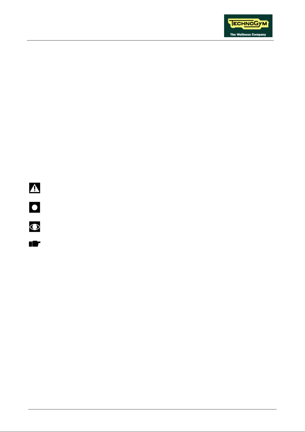
This manual contains notices and symbols which have specific meanings:
WARNING: non observance may result in accident or injury.
ATTENTION: non observance may cause damage to the machine.
Information about the operation in progress.
OBSERVE: observation about the operation in progress.
1.2. RECOMMENDATIONS
Technogym recommends the following steps for planning repair procedures:
• Carefully evaluate the customer’s description of the machine malfunction and ask all the
necessary questions to clarify the symptoms of the problem.
• Clearly diagnose the causes of the problem. This manual provides the fundamental theoretical
basis, which must then be integrated by personal experience and attendance at the training
courses periodically offered by Technogym.
• Rationally plan the repair procedure so as to minimize the downtime necessary for procuring
spare parts, preparing tools, etc.
• Access the component to be repaired, avoiding any unnecessary operations. In this regard it will
be useful to refer to the disassembly sequence described in this manual.
Page 1.1
Page 10

RUN XT: Service & Maintenance Manual - rev. 2.0
1.3. GENERAL RULES FOR REPAIR PROCEDURES
1. Always mark any parts or positions which may be confused with each other at the time of
reassembly.
2. Use original Technogym spare parts and lubricants of the recommended brands.
3. Use special tools where specified.
4. Consult the technical circulars, which may contain more up-to-date information on adjustments
and maintenance than those contained in this manual.
5. Before starting the repair procedure, make sure that the recommended tools are available and in
good condition.
6. For the procedures described in this manual, use only the specified tools.
WARNING: The tool sizes quoted in this manual are expressed in mm.
Page 1.2
Page 11
RUN XT: Service & Maintenance Manual - rev. 2.0
2. TECHNICAL CHARACTERISTICS
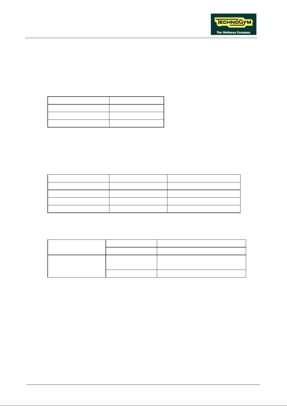
2.1. MECHANICAL CHARACTERISTICS
Width 80 cm
Length 190 cm
Height 142 cm
Weight 183 kg
2.2. ELECTRICAL CHARACTERISTICS
There are two separate models of the machine for 220 and 110 V mains electricity supplies, which
differ in certain components detailed in paragraph 2.7. :
110 Model 220 and 220 USA Models
Mains voltage 115 VAC 230 VAC
Frequency 50 - 60 Hz 50 - 60 Hz
Consumption ~ 1800 Watt - 8 A ~ 1800 Watt - 8 A
Fuses 5x20 4 A slow-blow 5x20 4 A slow-blow
2.3. AMBIENT SPECIFICATIONS
Temperature Operating from 5° to 35° C
Storage from -20 to 55° C
Humidity Operating from 30% to 80% non-
condensing
Storage from 5% to 85% non-condensing
2.4. CONFORMITY TO REGULATIONS
The machine conforms to the following directives:
• EMC Directive 89/336/EEC.
• LVD Directives 73/23/EEC and 93/68/EEC.
And is therefore certified with the EC Mark.
The US version of the machine, both for 110 and 220 V mains supply, conforms to the UL 1950
standard.
Page 2.1
Page 12
RUN XT: Service & Maintenance Manual - rev. 2.0
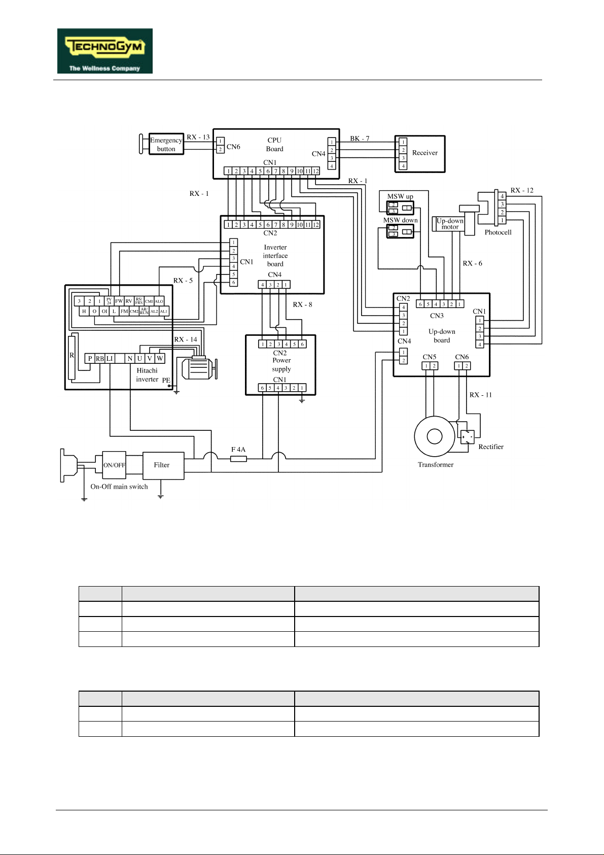
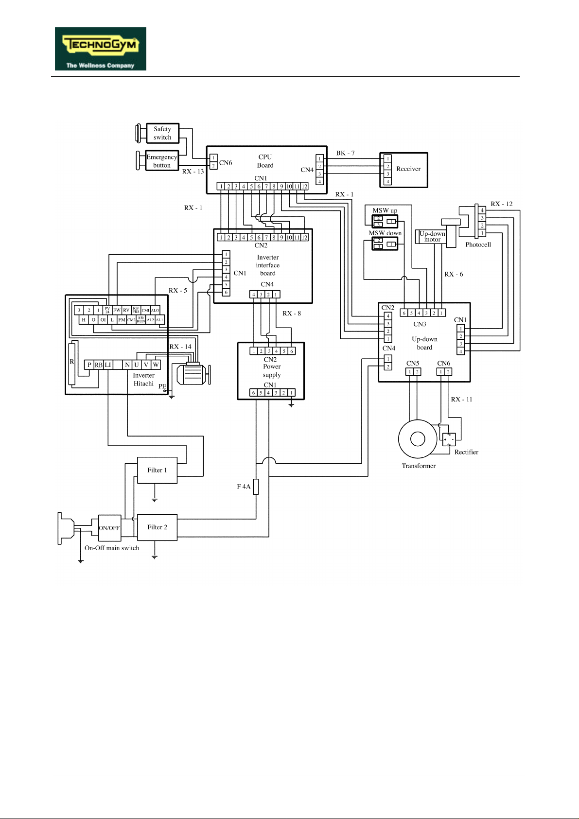
2.5. WIRING DIAGRAM FOR THE 220 MODEL
2.5.1. CONNECTORS
• CPU board
name type of connector connection
CN1 AMP MATE-N-LOCK 12-pin F. to up-down and inverter interface boards
CN2 AMP MODU II 2-pin M. to emergency button
CN4 AMP MODU II 4-pin M. to cardio receiver
• Power supply
name type of connector connection
CN1 PANDUIT 6-pin to mains electricity supply
CN2 PANDUIT 8-pin to inverter interface board
Page 2.2
Page 13
RUN XT: Service & Maintenance Manual - rev. 2.0
Status (pulse every ½
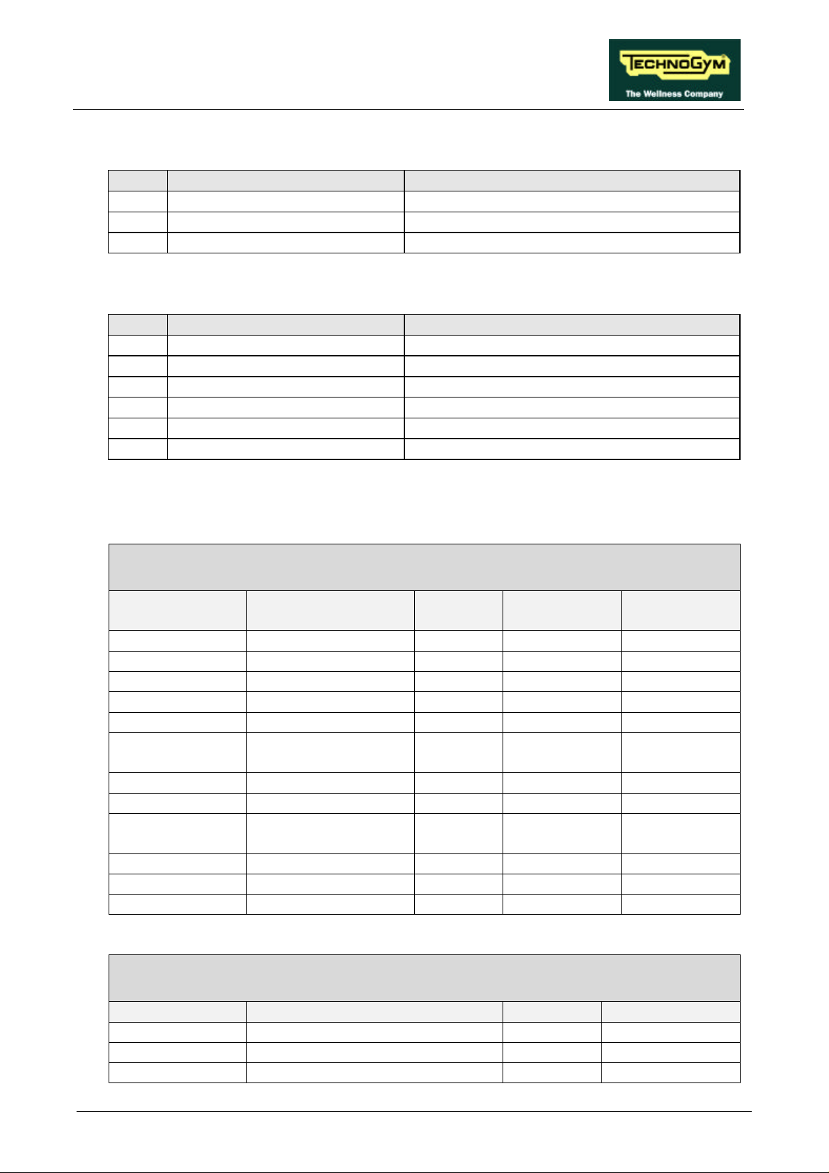
• Inverter interface board
name type of connector connection
CN1 AMP MATE-N-LOCK 6-pin F. to inverter
CN2 AMP MATE-N-LOCK 12-pin F. to CPU board
CN4 AMP MOD I 4-pin M to power supply
• Up-down board
name type of connector connection
CN1 AMP MOD II 4-pin M. to photocell
CN2 AMP MATE-N-LOCK 4-pin F. to CPU board
CN3 AMP MATE-N-LOCK 6-pin F. to up-down motor
CN4 AMP MATE-N-LOCK 2-pin F. to mains electricity supply
CN5 Sauro 2-pin to transformer
CN6 Sauro 2-pin to rectifier bridge
2.5.2. WIRING
CPU/CN1 Signal Color Inverter interf.
1 +12 V Blue 1 1 2 + 5 V Brown 1 2 3 ground Gray 1 3 4 -12 V White 5 5 not used Violet 12 6 Tread belt speed
7 Start Black 8 8 Inverter alarm Orange 9 9
10 Up Pink - 2
11 Down Blue 2 - 3
12 ground Gray 2 - 4
RX-1: Internal connection cable
CPU – Inverter interface board – Up-down board
board /CN2
Red 10 -
reference (PWM)
Brown 2 - 1
degree)
Up-down
board/CN2
CPU/CN4 Signal Color Receiver
BK-7: Heart rate monitor cable
CPU – Cardio receiver
1 +5 V Red 1
2 Pulse per beat Blue 2
3 ground Black 3
Page 2.3
Page 14
RUN XT: Service & Maintenance Manual - rev. 2.0
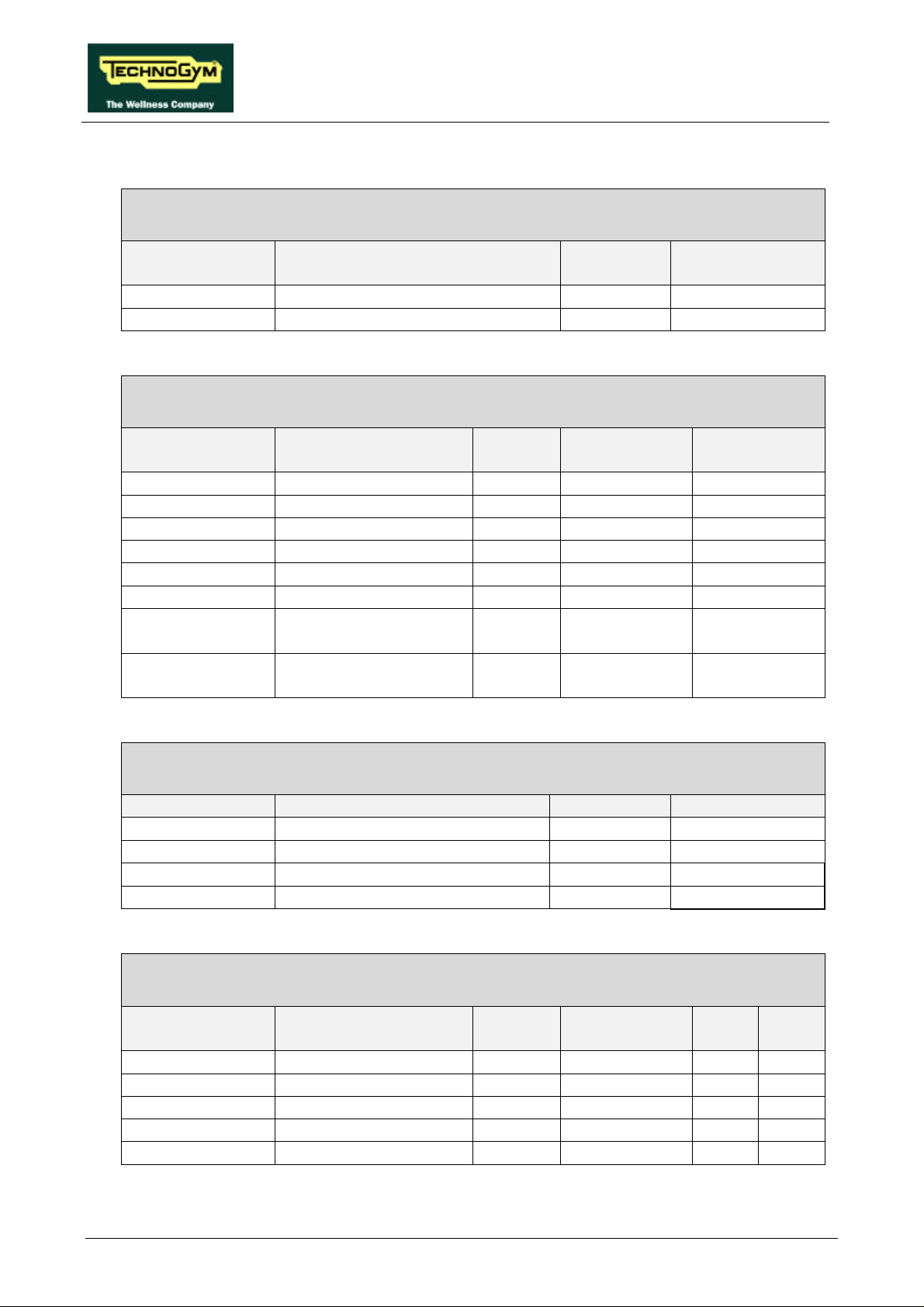
RX-13: Emergency button cable
CPU – Emergency button
CPU/CN2 Signal Color Emergency
button
1 NC contact Brown 1
2 Reference Blue 2
RX-5: Inverter cable
Inverter interface board – Inverter – Motor thermal cutout
Inverter interf.
board / CN1
1 Reference White PV24 -
- Thermal cutout reference Red PV24 1
- NC thermal cutout Red 1 2
2 Start Gray FW 3 NC Alarm Violet AL1 4 Alarm reference Red AL0 5 Inverter control
6 Inverter control
Signal Color Inverter Motor thermal
cutout
Brown 0 -
(0-10 Vdc)
Black L -
reference
RX-14: Belt motor cable
Inverter – Belt motor
Inverter Signal Color Belt motor
U Phase U Blue U
V Phase V Black V
W Phase W Brown W
PE ground Yellow-Green Casing
RX-6: Up-down motor cable
Up-down board – Up-down motor – Limit Switches
Up-down
board / CN3
1 Motor power supply Brown 1 - 2 Motor ground Blue 2 - 3 NO upper limit White - 3 4 NC lower limit switch Violet - - 2
6 Limit switch ground Black - 1 1
Signal Color Up-down
motor
UpperLSLower
LS
Page 2.4
Page 15
RUN XT: Service & Maintenance Manual - rev. 2.0
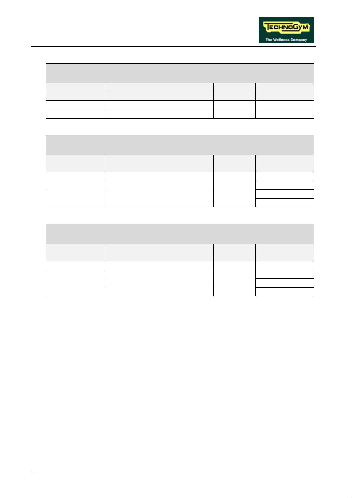
RX-11: Up-down motor power supply cable
Up-down board – Rectifier bridge
Up-down board Signal Color Rectifier bridge
CN6
1 48 Vac Red +
2 Ground Black
RX-12: Photocell cable
Up-down board – Photocell
Up-down
board / CN1
1 + 5 Vdc Red 1
2 Clock Orange 2
3 Direction Blue 3
4 ground Black 4
Signal Color Photocell
−
RX-8: Low voltage power supply cable
Power supply – Inverter interface board
Power supply/
CN2
1 + 5 V Yellow 4
2-4-5 Ground Black 3
3 + 12 V Red 2
6 - 12 V Blue 1
The high voltage power supply cables and the ground connections are not described here, in that
they can be easily determined from the wiring diagram above.
Signal Color Inverter interf.
board / CN4
Page 2.5
Page 16
RUN XT: Service & Maintenance Manual - rev. 2.0
2.6. WIRING DIAGRAM FOR THE 220 USA MODEL
The differences between the 220 USA Model and the 220 Model are:
• power supply cable;
• high voltage wiring;
• use of separate filters for the inverter and the power supply - up-down board;
• presence of an additional emergency device called a "Safety Switch" in series with the standard
emergency button. This device consists of a reed relay and a magnet, connected to a cable which
clips onto the user running on the machine. If the user moves away from the display, the cable is
pulled taut and eventually detaches the magnet when the distance becomes excessive. The
absence of the magnet causes the reed relay to commutate from closed to open, generating the
emergency signal. The safety switch requires cable RX-13 to be modified as follows:
Page 2.6
Page 17
RUN XT: Service & Maintenance Manual - rev. 2.0
RX-13 USA: Emergency cable
CPU – Emergency button – Safety switch reed relay
CPU/CN2 Signal Color Emergency
button
1 NC contact Brown 1 -
- NC contact Blue 2 1
2 Reference Orange - 2
OBSERVE: An upgrade kit is available (code 0WK247) for installing the safety switch
on European machines.
The other cables are unchanged. Therefore, for their description, refer to the details provided for the
220 Model.
Safety
reed relay
Page 2.7
Page 18
RUN XT: Service & Maintenance Manual - rev. 2.0
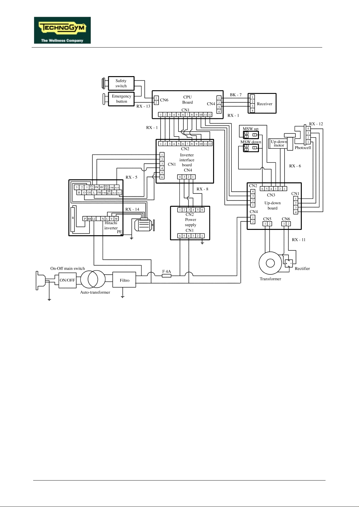
2.7. WIRING DIAGRAM FOR THE 110 MODEL
The differences between the 110 Model and the 220 Model are:
• the automatic circuit breaker is 20 A - class D instead of 10 A - class C;
• autotransformer 110 - 220;
• mains lead with different cable section and plug;
• presence, as on the 220 USA Model, of the safety switch.
As regards the wiring, the safety switch uses cable RX-13 USA, while the other cables remain
unvaried. Therefore, for their description, refer to the details provided for the 220 and 220 USA
Models.
Page 2.8
Page 19

RUN XT: Service & Maintenance Manual - rev. 2.0
3. PRINCIPLES OF OPERATION
3.1. BLOCK DIAGRAM
The machine block diagram is shown in the figure below:
(1) CARDIO TRANSMITTER
It is worn by the person using the machine, and transmits to the cardio receiver one pulse for
every heart beat that is detected.
(2) CARDIO RECEIVER
It is connected to the machine’s CPU board and receives the pulses sent by the transmitter. Its
reception area is approximately a circle of 1 meter of radius. If there is electromagnetic noise
Page 3.1
Page 20

RUN XT: Service & Maintenance Manual - rev. 2.0
(produced by high voltage lines, radio transmitters, monitors, motors, etc.) within its reception
area, the receiver becomes saturated and stops receiving any signal. If there are 2 transmitters
within its area of reception, it will receive signals from both, and may produce an error or
irregular reading.
(3) CPU BOARD
This is the heart of the machine, which controls all the machine functions by executing the
program stored in EPROM. It receives information from the user (age, weight, etc.) during
set-up of the training session, from the cardio receiver (user’s heart rate), from the inverter
interface board and from the up-down interface board. It controls the speed selected with the
“+” “−” keys and the elevation selected with the “↑” “↓” keys or according to the chosen
training program. It receives the error signal from the inverter interface board and the status
signal from the up-down interface board
(4) INVERTER INTERFACE BOARD
Receives from the display a PWM signal proportional to the selected speed, and converts it
into a continuous voltage for controlling the inverter. Receives the error signal generated by
the inverter in the event of problems and transmits it to the display. Receives the low voltages
output by the power supply and passes them to the display. There are 2 LEDs on the board:
DL1 illuminates when the tread belt is moving, while DL2 illuminates when the inverter does
not detect any error conditions and therefore the alarm signal is inactive.
(5) UP-DOWN BOARD
Receives from the display the enable signal for elevation motion and converts it into a control
for the up-down motor. Generates its power supply and the DC power supply for the motor by
means of a transformer and rectifier bridge. Determines the motor position, and hence the
treadmill elevation, by means of the photocell. Generates and sends to the display a motion
status signal at every 0.5% variation in the elevation. Checks the lower and upper travel limits
by means of 2 limit switches. The board includes 2 LEDs associated to the limit switches,
which are normally illuminated: DL1 comes off when the upper limit switch is tripped, while
DL3 comes off if the lower limit switch is tripped.
(6) INVERTER
This is the device which supplies the three-phase belt motor. It receives a DC control voltage
from the inverter interface board. Variations in this voltage cause corresponding variations in
the operating frequency of the inverter/motor, and hence change the speed of the tread belt. It
handles motor drive errors and, in the event of an error, shuts down the power supply to the
motor and sends an alarm signal through the interface board to the display. The event which
caused the error is memorized as an error code.
(7) PHOTOCELL
This is the device which provides feedback on the motion of the up-down motor. It transmits
one pulse for each slot detected on the encoder which is fixed to the gearmotor, and a signal
indicating the direction of movement. The up-down board, receiving the pulses, sends the
status signal to the display which stops the motor when the number of pulses received
coincides with the desired elevation.
Page 3.2
Page 21

RUN XT: Service & Maintenance Manual - rev. 2.0
(8) UP-DOWN MOTOR
It is a DC motor which, by means of a mechanical reduction unit and a timing belt, turns the
lead screw nuts on the threaded elevation bars, causing the machine to be raised or lowered
depending on the direction of rotation.
(9) BELT MOTOR
An asynchronous three-phase motor which, by means of a pulley and a poly-v belt, turns the
driving roller of the tread belt. Each motor phase is equipped with a normally-closed bimetallic
safety which opens when the temperature exceeds a preset threshold, in order to safeguard the
integrity of the motor. The 3 bimetallic safeties are connected in series and reach the inverter as
a NC external input signal. When this contact opens, the inverter generates an alarm.
(10) LIMIT SWITCHES
There are 2 limit switches which control the range of motion of the elevation mechanism.
These switches are positioned at the travel limits of the elevation bars, and change state when
pressed and/or released. The lower limit switch is NC, while the upper one is NO.
(11) POWER SUPPLY
Receives the mains voltage at its input and outputs the DC voltages (+5 V, +12 V and −12 V)
which supply the display and the inverter interface board.
Page 3.3
Page 22

RUN XT: Service & Maintenance Manual - rev. 2.0
3.2. TREAD-BELT MOTOR DRIVE
The tread belt is actuated by the motor through a linkage consisting of the motor pulley, the driving
roller and the belt which connects them. In this way, a given belt motor speed corresponds to a
predetermined linear tread belt speed. The belt motor is controlled by the inverter which generates a
variable-frequency sine wave signal: variations in frequency cause the motor speed and hence the
tread belt speed to vary.
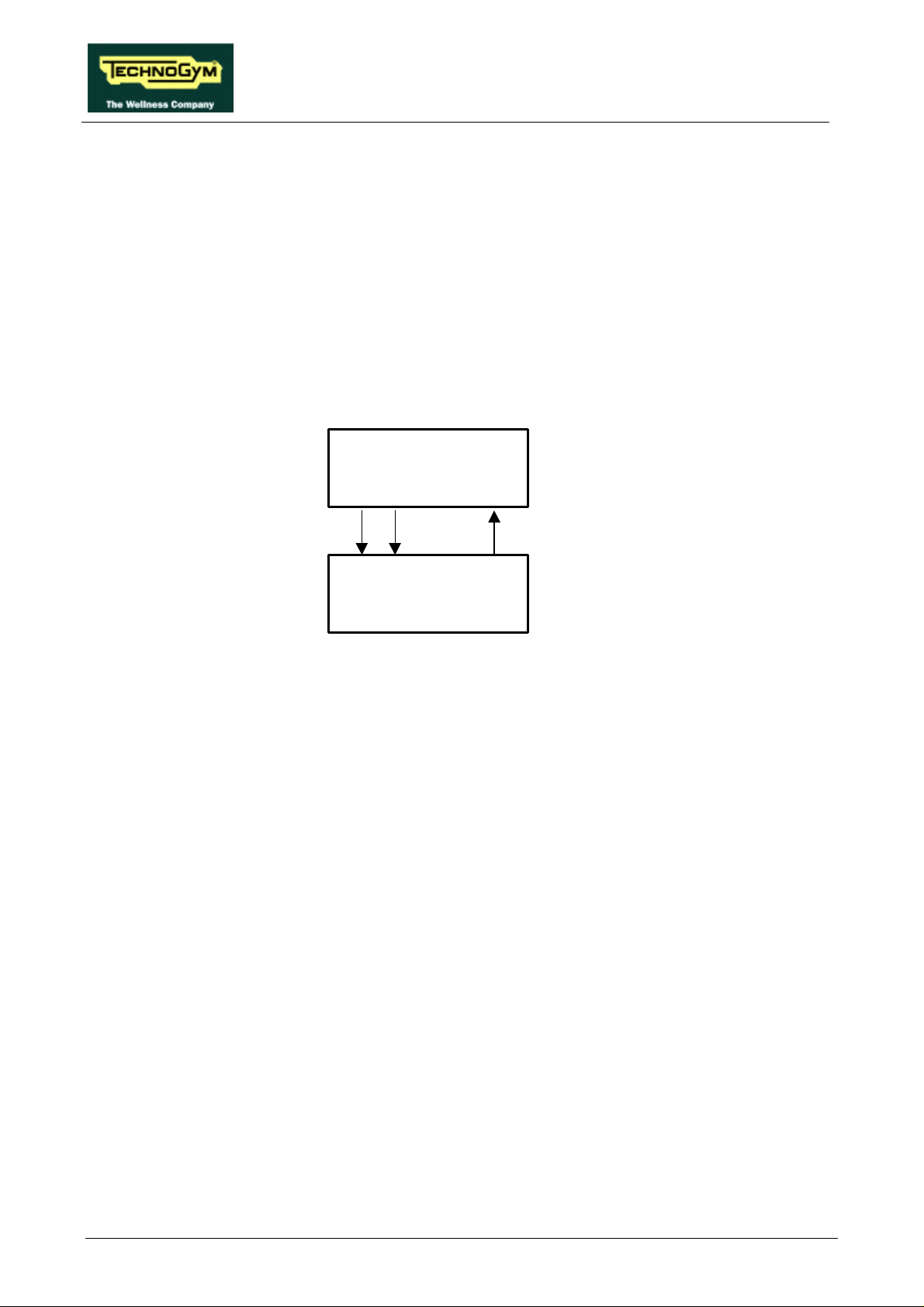
The machine controls the speed of the belt motor by means of the CPU board and the inverter
interface board, as shown in the figure below:
CPU board
StartPWM
Inverter
interface board
Vref
The speed control utilizes 3 signals:
• Start signal
This is the signal generated by the CPU to enable starting of the motor (pin 7-3 of connector
CN1 on the CPU board). When the tread belt is stopped this signal is at logic level low (0 Vdc),
whereas immediately after the “Start” button on the display is pressed it goes high (4.5 Vdc).
The signal enters the inverter interface board (pin 8-3 of connector CN2 on the inverter interface
board), is processed and sent to the inverter (pin 2-1 of connector CN1 on the inverter interface
board). In the belt-stopped condition it is -24.7 Vdc, while immediately after pressing the “Start”
button on the display it is -2.7 Vdc.
Start
Inverter
Alarm
Alarm
• Speed reference signal
This is the signal generated by the CPU (pins 6-3 of connector CN1) to control the motor speed.
It is a PWM signal, that is to say a fixed frequency square wave with a variable duty cycle. The
logic of this control has the duty cycle decreasing with increasing speed. The measurement of its
DC component with a multimeter shows a value that decreases with increasing speed, from a
maximum of approximately 5 Vdc down to a few hundred mVdc.
This signal enters the inverter interface board (pins 10-3 of connector CN2), is converted into a
variable analogue signal between 0 and 10 Vdc and sent to the inverter (pins 5-6 of connector
Page 3.4
Page 23

RUN XT: Service & Maintenance Manual - rev. 2.0
CN1 on the inverter interface board). The signal input to the inverter increases with increasing
speed.
The relationship between the speed reference and the inverter frequency is determined by the
programming of the inverter.
• Alarm signal
This is the signal generated by the inverter if a problem is detected in the motor drive, or if the
motor thermal cutouts open. It enters the inverter interface board (pins 3-4 of connector CN1)
and its value is 0 Vdc under normal conditions, 10 Vdc under alarm conditions.
The signal is then sent to the inverter interface board (pins 9-3 of connector CN2) to the CPU
board (pins 8-3 of connector CN1) and is 5 Vdc under normal conditions, 0 Vdc under alarm
conditions. When this alarm signal switches to 0 Vdc, the CPU disables the Start signal, resets
the PWM signal and shows the E3 or E4 error message on the display.
Page 3.5
Page 24
RUN XT: Service & Maintenance Manual - rev. 2.0
3.3. UP-DOWN MOTOR DRIVE
The elevation of the machine is varied by the up-down motor which, by means of a timing belt, turns
the lead screw nuts on the 2 elevation bars. The motor has an integral encoder wheel which, by
means of a photocell, provides the motor motion control signal: each motor revolution corresponds
to a predetermined number of pulses and to a predetermined displacement on the elevation bars.
The direction of rotation of the motor determines whether the treadmill moves upward or
downward.
The machine controls the elevation through the CPU board and the up-down interface board as
shown in the figure below:
CPU board
StatusDownUp
Up-down
interface board
The elevation control utilizes 3 signals:
• Up signal
This is the signal generated by the CPU (pins 10-12 of connector CN1) to enable movement of
the up-down motor in the upward direction. Under normal conditions the signal is at logic level
low (0 Vdc), and it goes high (5 Vdc) to actuate the motor. The signal remains high for the entire
duration of the movement.
The signal enters the up-down board (pin 2-4 of connector CN2) and enables movement of the
motor in the desired direction.
• Down signal
This is the signal generated by the CPU (pin 11-12 of connector CN1) to enable movement of the
up-down motor in the downward direction. Under normal conditions the signal is at logic level
low (0 Vdc), and it goes high (5 Vdc) to actuate the motor. The signal remains high for the entire
duration of the movement.
The signal enters the up-down board (pin 3-4 of connector CN2) and enables movement of the
motor in the desired direction.
• Status signal
This is the signal generated by the up-down board whenever the photocell detects a number of
pulses corresponding to an 0.5% variation in the elevation. This signal (pin 1-4 of connector CN2
of the up-down board) is normally at logic level low (0Vdc) and goes high (5 Vdc) for a few
msec.
The CPU board receives this signal (pin 9-12 of connector CN1) which indicates the actual
elevation of the machine. Comparing it with the desired elevation value, the CPU determines
Page 3.6
Page 25

RUN XT: Service & Maintenance Manual - rev. 2.0
whether to keep the Up or Down signal asserted to continue the movement or, if the desired
elevation has been reached, to reset the Up or Down signal.
If, after having asserted the Up or Down signal, the CPU board does not receive any Status
signal within a predetermined period of time (a few seconds), it resets the asserted signal and
displays error code E5 to indicate absence of movement.
Page 3.7
Page 26

RUN XT: Service & Maintenance Manual - rev. 2.0
Page intentionally left blank
Page 3.8
Page 27
RUN XT: Service & Maintenance Manual - rev. 2.0
4. ACCESSORIES
4.1. CONNECTING TO THE TGS
The machine can be connected to the Technogym System by means of the 9-pin D-type connector
situated on the back of the display, which provides the RS 232 serial port for connecting the TGS
reader.
The serial port is connected to the CPU by the cable described below, which is supplied in the
upgrade kit:
TGSRN2XT: Internal cable
CPU - 9-pin connector
CPU/CN2 Signal Color DB9 male
1 + 12 V yellow 1
2 Tx brown 3
5 Rx white 2
6 ground green 5
To prevent interference with the cardio receiver, route the cable behind cable RX-1 and
connector CN1 of the CPU board, as described in paragraph 11.1. .
For all further information, including troubleshooting, refer to the following manual: “Technogym
System: Installation Guide”.
Page 4.1
Page 28

RUN XT: Service & Maintenance Manual - rev. 2.0
Page intentionally left blank
Page 4.2
Page 29

RUN XT: Service & Maintenance Manual - rev. 2.0
5. INSTALLATION INSTRUCTIONS
5.1. SPECIFICATIONS AND REQUIREMENTS
For correct machine installation, make sure that:
1. The machine is installed on a level surface that is free of vibrations and has sufficient carrying
capacity for the combined weight of the machine and user.
2. The environment is dust or sand free.
3. The environment meets the operating temperature and humidity conditions specified in paragraph
2.3. .
4. The machine is not positioned close to sources of heat, sources of electromagnetic noise
(television sets, electric motors, antennas, high voltage lines, appliances etc…) or medical
equipment.
5. To eliminate any interference with the cardio receiver, there should not be any transmitters at a
distance of 100 cm from the display.
6. The mains voltage must match the value specified on the machine rating plate.
7. The electrical system must be provided with an efficient ground connection.
8. The wall outlet used should be reserved for the machine and have a rating of at least 1800 Watt.
9. Do not connect other machines or users to the same wall outlet.
10. Position the mains lead of the machine where is will not be underfoot. For this purpose, it is
recommended to use the special trackways supplied with the machine.
5.2. INSTALLATION
To correctly install the machine, proceed as follows:
1. Ensure that the specifications and requirements for installation have been met (see paragraph 5.1.
).
2. Remove the machine from its packing materials: one carton fixed to a wooden pallet for overseas
shipment, one nylon bag for Italy. For machines shipped in cartons, the side uprights and handles
are disassembled and placed on the tread belt.
3. Position the machine as specified above, on a level surface that is free of vibrations and has
sufficient carrying capacity for the combined weight of the machine and the user.
4. For machines which shipped in a carton, it is necessary to reassemble the components that were
disassembled for transport. Follow the procedure for assembling the side uprights and handles
described in the "Operating and service instructions" supplied with each machine.
5. Connect the mains lead to the inlet socket on the machine.
6. Place the on/off switch in the “0” position.
7. Plug the mains lead into the electrical outlet.
Page 5.1
Page 30

RUN XT: Service & Maintenance Manual - rev. 2.0
5.3. FIRST POWER-ON
After completing the installation procedure, the machine is ready to be powered up. To turn on the
machine, simply toggle the on/off switch from the 0 position to the 1 position.
When the machine is turned on it will perform a power-on test which:
• sounds the buzzer;
• lights all the LEDs.
• resets the elevation
After completing this power-on test the machine enters standby mode, awaiting a keyboard
command.
To check the correct operation of the machine:
• get on the machine;
• press the "Start" key on the keyboard to begin exercising;
• check that the belt motor starts;
• press the “+” and “−” keys on the keyboard and check that the tread belt speed changes
accordingly;
• press the “↑” and “↓“ keys on the keyboard and check that the machine elevation changes
accordingly;
• put on the heart rate transmitter and check that the machine correctly measures the heart rate
value.
Page 5.2
Page 31
RUN XT: Service & Maintenance Manual - rev. 2.0
6. TROUBLESHOOTING
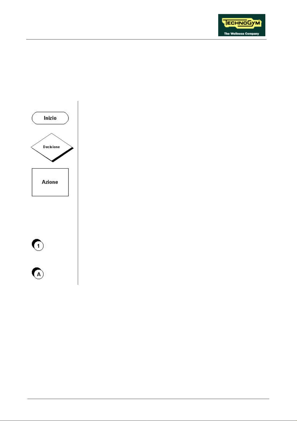
The troubleshooting procedures are shown in the form of flow charts. In order to facilitate
consultation, the following standard box shapes are used.
This type of box is the START point of the troubleshooting procedure. It
typically contains a description of the problem or malfunction.
This type of box represents a decision point in the troubleshooting procedure.
It typically contains a description of the DECISION to be made, with an
outcome that can be either a positive (YES) or negative (NO) response.
This type of box corresponds to a step in the troubleshooting procedure where
an ACTION must be carried out. It typically contains a description of the
ACTION necessary to resolve the problem. Therefore, after executing the
specified ACTION:
1. Check whether the problem has been resolved;
2. If the problem persists, it is recommended to resume the troubleshooting
procedure from the point before the action was carried out.
A circled number (such as that shown on the left) next to a box of the
troubleshooting procedure indicates that detailed instructions for performing
that particular check or action are provided below the flowchart.
A circled letter (such as that shown on the left) is used to highlight a point in
the procedure. Typically, this indicator is used in page changes.
Page 6.1
Page 32
RUN XT: Service & Maintenance Manual - rev. 2.0
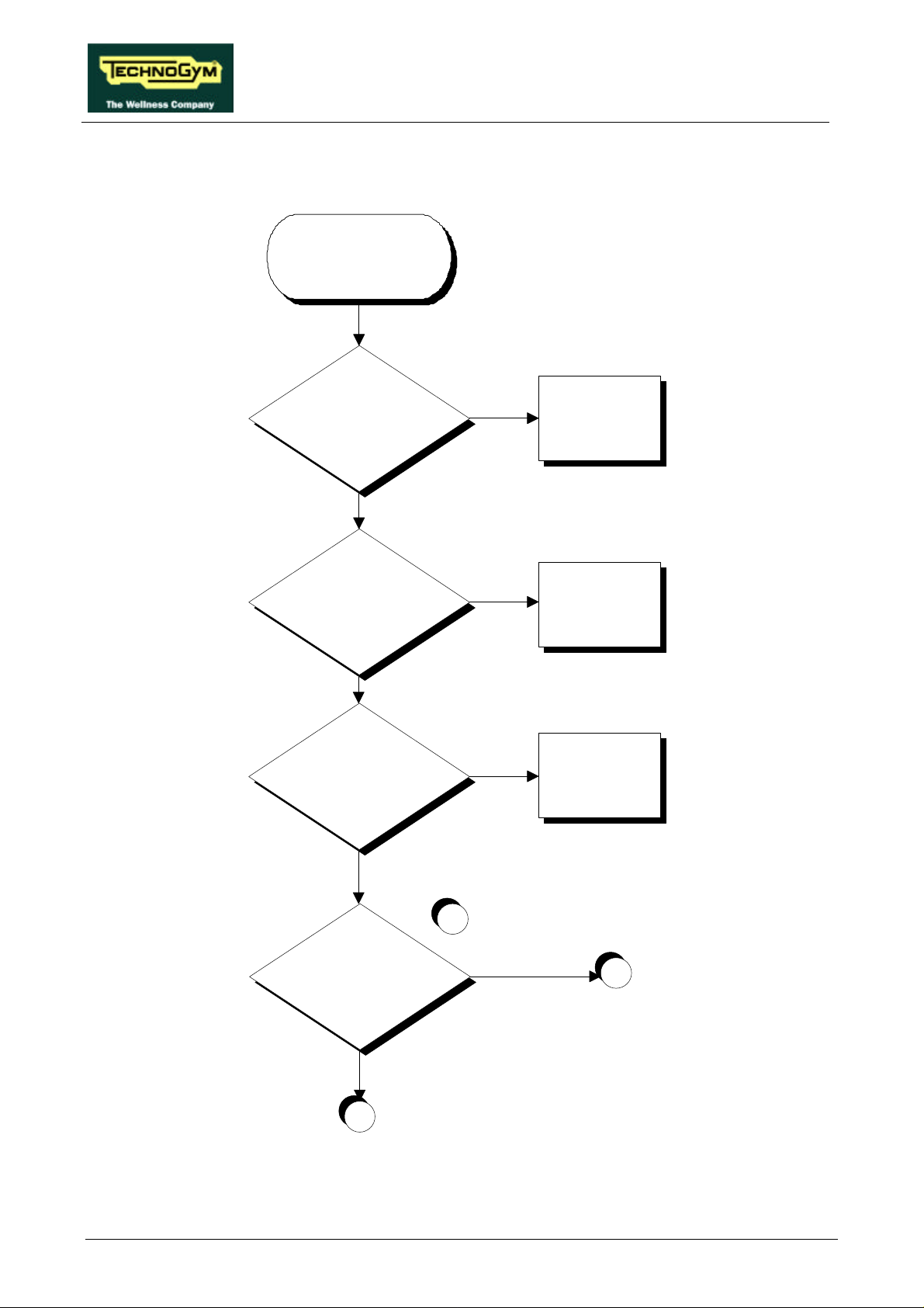
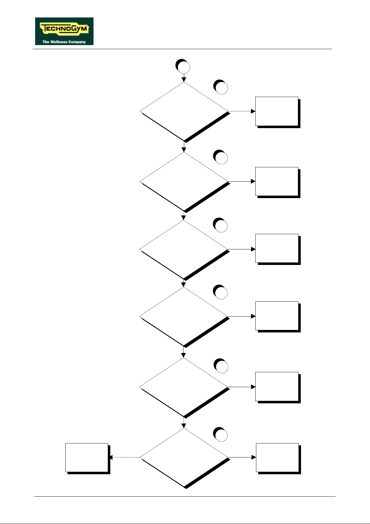
6.1. THE DISPLAY DOES NOT ILLUMINATE
THE DISPLAY
DOES NOT
ILLUMINATE
Is the fuse OK?
YES
Is mains lead OK?
YES
Does the wall output supply the
correct voltage?
NO
NO
NO
Replace the blown fuse
Replace the mains lead
Connect machine to a
suitable
electrical output
Is the mains voltage present at
the power supply input?
Continued on the following page.
Page 6.2
YES
1
NO
B
YES
A
Page 33
RUN XT: Service & Maintenance Manual - rev. 2.0
A
YES
2
Are DC voltages output by the
power supply correct?
YES
Do all DC voltages reach the
display?
NO
Do all DC voltages reach the
inverter interface board?
NO
Replace the power
supply: see paragraph
7.12.
3
YES
Replace the display
CPU board: see
paragraph 7.3.
4
NO
Replace cable RX-8
connecting the power
supply to the inverter
interface board
Are all DC voltages present at
the output of the inverter
interface board?
Replace cable RX-1
*alternator interface
board to the display
Continued on the following page.
YES
YES
connecting the
5
NO
Replace the inverter
interface board: see
par. 7.12.
Page 6.3
Page 34
RUN XT: Service & Maintenance Manual - rev. 2.0
B
6
Is the mains voltage present at
the output of the power input
socket?
YES
Is the mains voltage present at
the input to the automatic circuit
breaker?
YES
Is the mains voltage present at
the output of the automatic
circuit breaker?
NO
Replace the power
input socket of the
machine
7
NO
Replace the cable
connecting the input
socket to the
automatic circuit
breaker
8
NO
Replace the
automatic circuit
breaker
Replace the wiring
between the filter -
fuse holder - power
suppl
YES
YES
Is the mains voltage present at
the input to the filter?
YES
Is the mains voltage present at
the output of the filter?
YES
Is the fuse holder continuity OK?
9
10
11
NO
NO
NO
Replace the cable
connecting the
automatic circuit
breaker to the filter
Replace the filter
Replace the fuse
holder
Page 6.4
Page 35
RUN XT: Service & Maintenance Manual - rev. 2.0
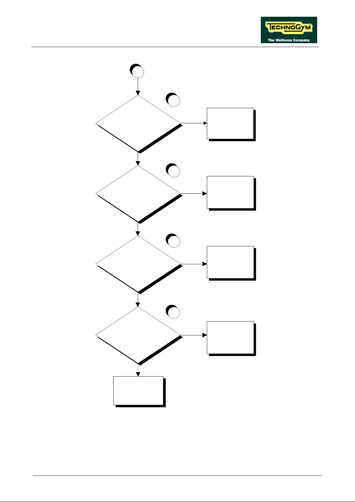
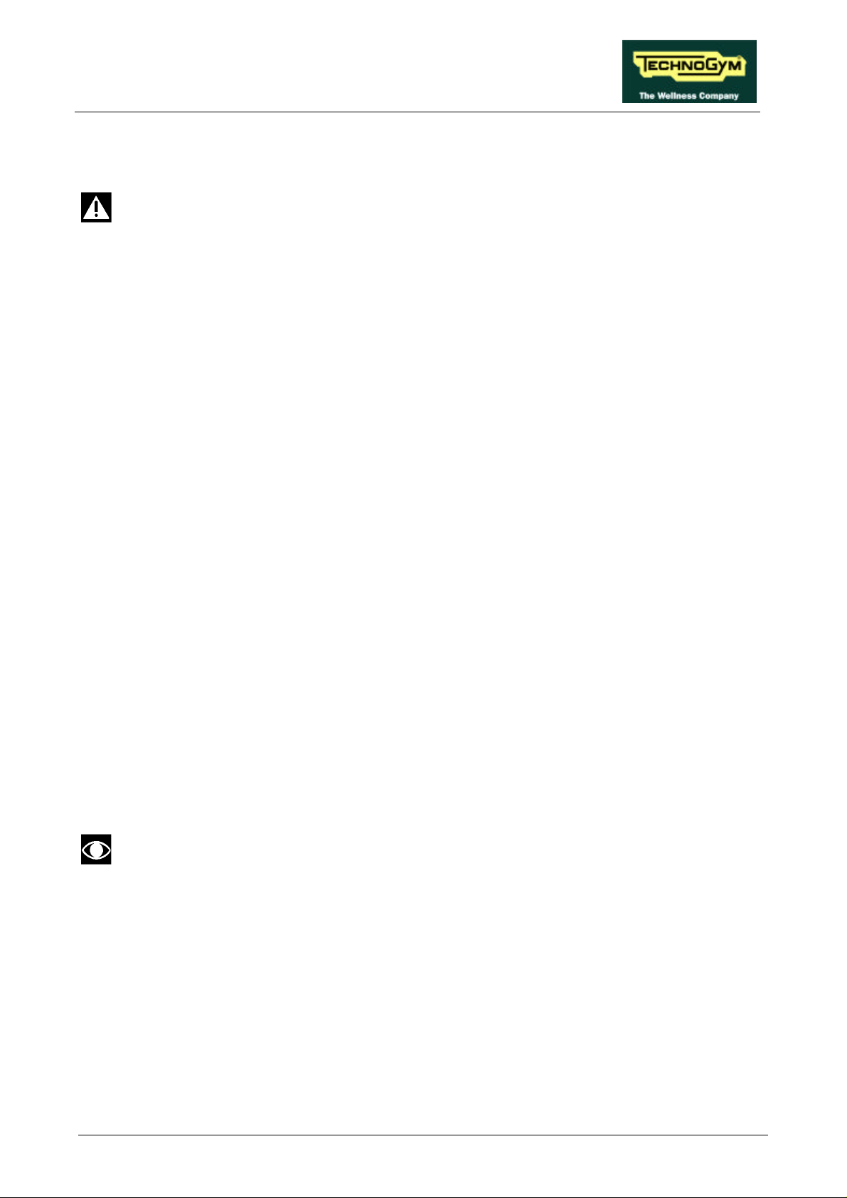
Follow the procedure step by step to correctly diagnose the problem. Take particular care with the
checks highlighted by circled numbers, which are described in detail below:
WARNING: Carry out these checks with the machine powered up.
(1) Slightly lift connector CN1 on the power supply. Place the tester probes between pins 4 and 6
on that connector. The measured voltage should be approximately 220 Vac or 110 Vac
depending on the type of mains electricity supply.
(2) Slightly lift connector CN2 on the power supply in order to access the pins with the tester
probes. Check that all the output voltages of the power supply are correct by referring to
paragraph 2.5.2. “Wiring”.
(3) As for point (2) but on connector CN1 of the display CPU board.
(4) As for point (2) but on connector CN4 of the inverter interface board.
(5) As for point (2) but on connector CN2 of the inverter interface board.
(6) Slightly lift the Fastons on the machine power inlet socket. Place the tester probes between the
live and neutral terminals of the connector. The measured voltage should be approximately 220
Vac or 110 Vac depending on the type of mains electricity supply.
(7) As for point (6) but on the input of the automatic circuit breaker.
(8) As for point (6) but on the output of the automatic circuit breaker.
(9) As for point (6) but on the input of the filter.
(10) As for point (6) but on the output of the filter.
(11) Using the tester probes, check the continuity of the fuse holder by measuring its resistance.
This is correct if the measured value is less than a few Ohms.
On certain machines, it has been found that the display turns off after the “Clear” key is
pressed. To solve this problem, mount a 15 Ohm 5 W resistor between pins 3 and 4 of
connector CN4 of the inverter interface board. This modification is standard on
machines starting from SN D241U 50000010 (USA), D240 50003665 (ITA) and D240
50003649 (UK) (production date 13/02/98).
Page 6.5
Page 36
RUN XT: Service & Maintenance Manual - rev. 2.0
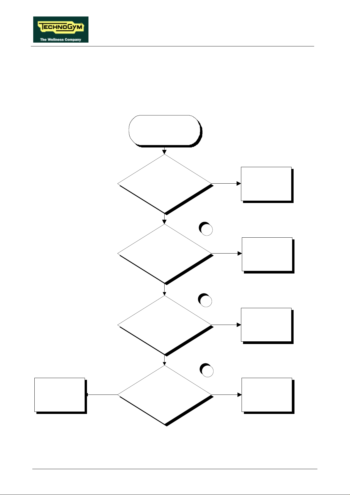
6.2. THE DISPLAY SHOWS “E1” OR “E2”
These messages are related to the emergency button. The machine displays:
• E1 if the emergency button is pressed during a training session.
• E2 if the emergency button is pressed at the start of a training session.
THE DISPLAY
SHOWS E1 / E2
Did the user press the emergency
button during the training session or
at the start?
NO
Is the SW version up to date?
YES
Is the voltage at the emergency
button terminals correct?
YES
Correct operation
1
NO
Update the SW of the
machine
2
YES
Replace the emergency
button: see paragraph
7.6.
NO
3
Replace cable RX-13
between the CPU board
and the emergency button
YES
Is the voltage at the output of the
CPU board correct?
NO
Replace the CPU board:
see paragraph 7.3.
Follow the procedure step by step to correctly diagnose the problem. Take particular care with the
checks highlighted by circled numbers, which are described in detail below:
Page 6.6
Page 37

RUN XT: Service & Maintenance Manual - rev. 2.0
(1) The SW version must be higher than EUR 2.4, USA 2.3, TGS EUR 2.2 or TGS USA 2.3.
(2) Place the tester probes between the terminals of the emergency button. When the button is
pressed the measured voltage should be +5Vdc, when it is released it should be 0 Vdc.
(3) Place the tester probes between pins 1 and 2 of connector CN2 of the CPU board. The
measured voltage should be +5Vdc.
Page 6.7
Page 38
RUN XT: Service & Maintenance Manual - rev. 2.0
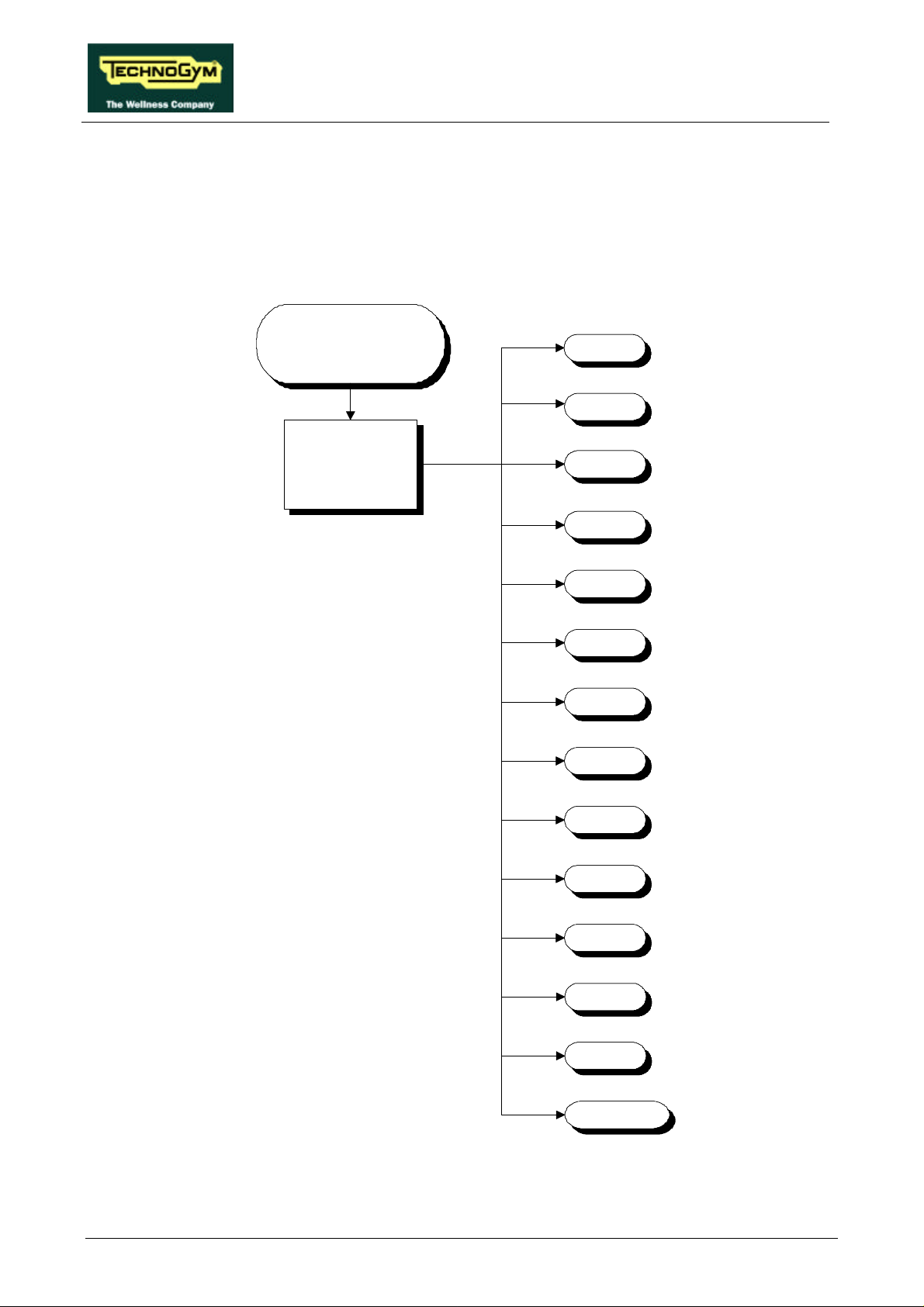
6.3. THE DISPLAY SHOWS “E3” OR “E4”
These messages are related to the belt motor group. The machine displays:
• E3 failure to actuate movement of the belt motor at the start of the training session;
• E4 the movement of the belt motor is interrupted during the training session.
THE DISPLAY
SHOWS "E3" OR
"E4"
Check the error message
displayed and/or
memorized by the inverter
E1
E2
E3
E4
E5
E6
E7
E8
E9
E10
E11
E12
E14
None
The paragraphs below illustrate the troubleshooting procedures for each individual error code.
Page 6.8
Page 39
RUN XT: Service & Maintenance Manual - rev. 2.0
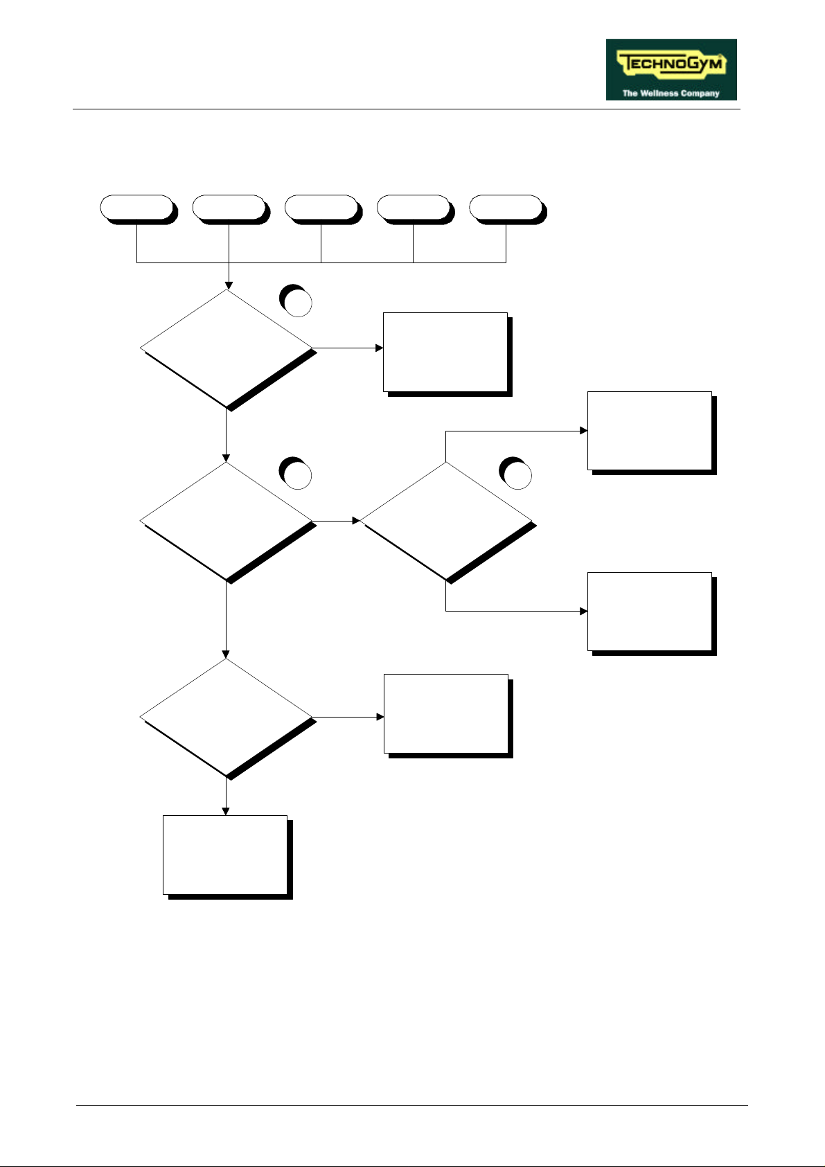
6.3.1. THE INVERTER DISPLAY SHOWS E1, E2, E3, E4 OR E5
These inverter error messages are related to output short-circuit problems.
E2 E3 E4 E5E1
1
Is the inverter output
short-circuited?
NO
Is there a short-circuit on the
motor cable terminals?
NO
Does the machine resume
correct operation after being
turned off for 1 minute?
YES
Replace the inverter: see
paragraph 7.13.
2 3
YES
Is the belt motor
short-circuited?
YES
Probable interference. The
machine is OK
YES
NO
Replace the belt motor:
see paragraph 7.11.
Replace the belt motor
cable
NO
Replace the inverter: see
paragraph 7.13.
Follow the procedure step by step to correctly diagnose the problem. Take particular care with the
checks highlighted by circled numbers, which are described in detail below:
(1) Disconnect the motor cable from the inverter and place the tester probes between its terminals
U-V, U-W and V-W. The measured resistance should be very high, in the order of MOhms. It
is difficult to obtain a stable resistance measurement, however, a phase can be considered
short-circuited or defective when the measured resistance is in the order of a few tens of
Ohms.
Page 6.9
Page 40

RUN XT: Service & Maintenance Manual - rev. 2.0
(2) Place the tester probes between the blue - black, blue - brown and black - brown wires of the
motor cable. The measured resistance should be approximately 3.1 Ohm.
(3) Disconnect the motor cable from the motor and place a tester between its terminals U-V, U-W
and V-W. The measured resistance should be 3.1 Ohm.
Page 6.10
Page 41
RUN XT: Service & Maintenance Manual - rev. 2.0
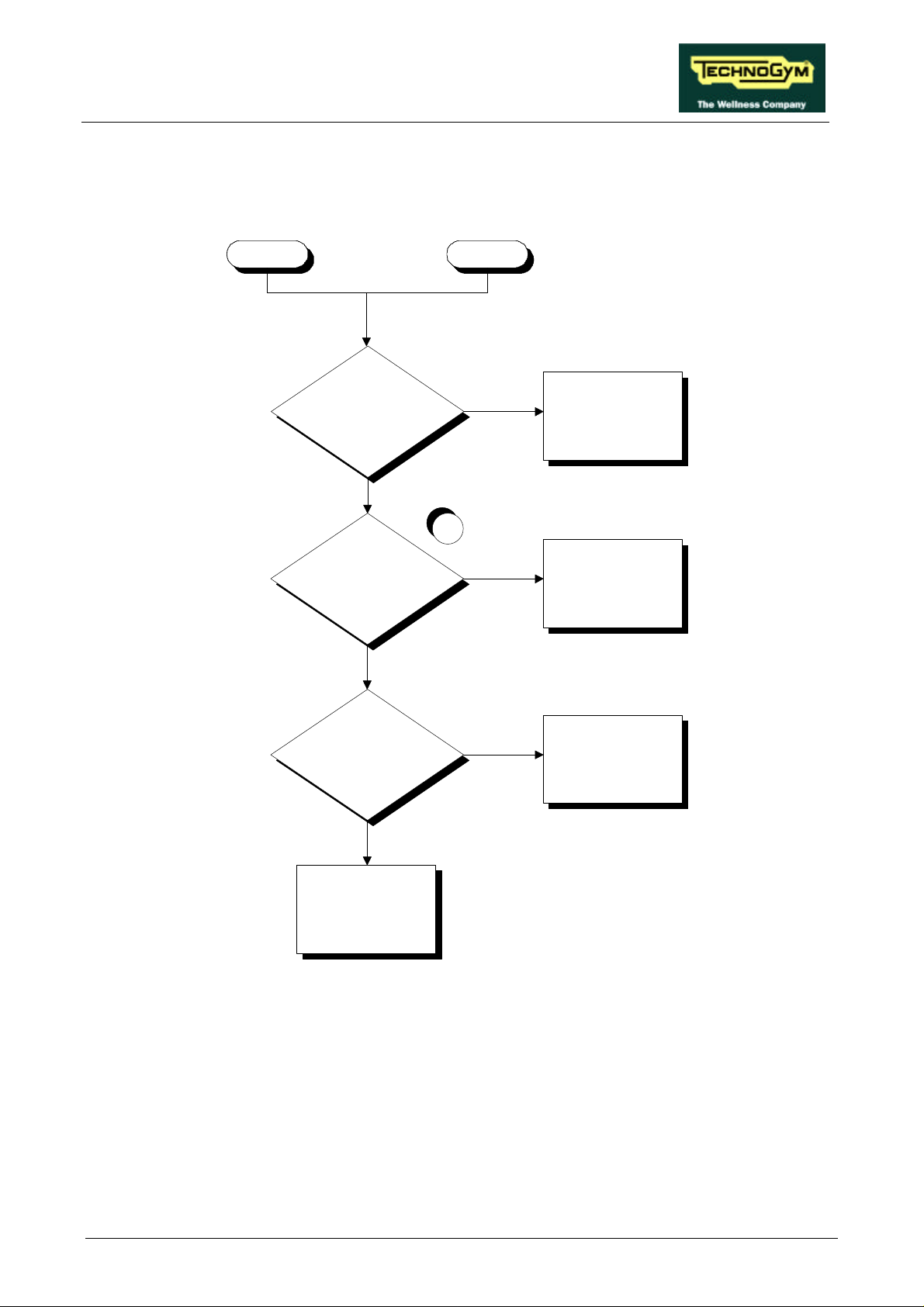
6.3.2. THE INVERTER DISPLAY SHOWS E6 OR E7
These inverter error messages are related to problems with the inverter braking group or the braking
resistor.
E7E6
Is the braking resistor
correctly connected to the
inverter?
YES
Is the value of the braking
resistance correct?
YES
Does the machine resume
correct operation after being
turned off for 1 minute?
NO
Reinstate the connection
1
NO
Replace the braking
resistor
YES
Probable interference. The
machine is OK
NO
Replace the inverter: see
paragraph 7.13.
Follow the procedure step by step to correctly diagnose the problem. Take particular care with the
checks highlighted by circled numbers, which are described in detail below:
(1) With the machine turned off, disconnect one of the resistor wires from the inverter terminal
block and place the tester probes across the resistor. The measured resistance should be 150
Ohm.
Page 6.11
Page 42
RUN XT: Service & Maintenance Manual - rev. 2.0
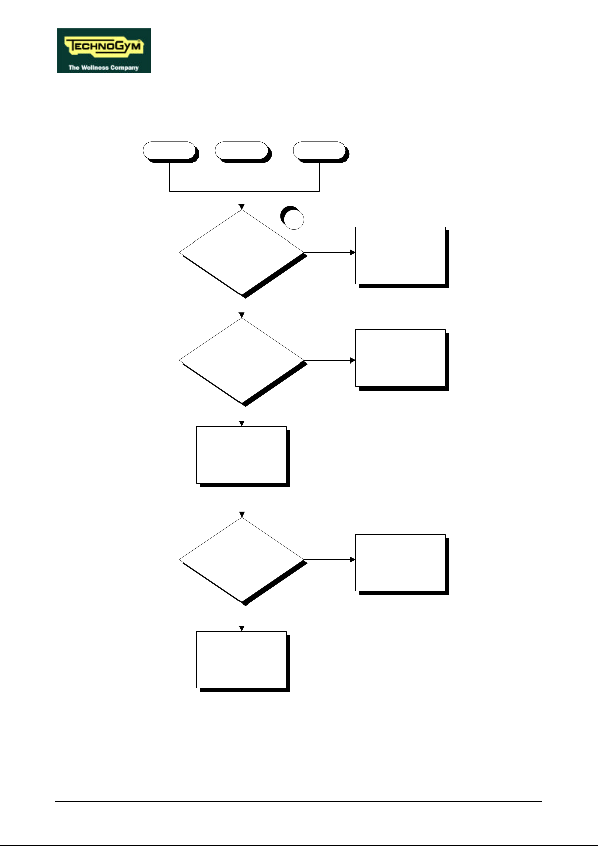
6.3.3. THE INVERTER DISPLAY SHOWS E8, E10 OR E11
These inverter error messages are related to HW and SW problems with the inverter.
E10E8 E11
1
Does the error occur
frequently?
NO
Does the machine resume
correct operation after being
turned off for 1 minute?
NO
Re-program the inverter:
see paragraph 9.1.
YES
YES
Replace the inverter: see
paragraph 7.13.
Probable interference. The
machine is OK
Does the machine resume
correct operation after being
turned off for 10 minutes?
YES
Programming correct. The
machine is OK
NO
Replace the inverter: see
paragraph 7.13.
Follow the procedure step by step to correctly diagnose the problem. Take particular care with the
checks highlighted by circled numbers, which are described in detail below:
Page 6.12
Page 43

RUN XT: Service & Maintenance Manual - rev. 2.0
(1) Determine the frequency of the errors by counting the number of occurrences in the inverter
error memory, and by running targeted checks. An error is considered frequent if it occurs 2 or
3 times a day.
WARNING: incorrect programming of the inverter can cause serious damage to the
machine or malfunctioning that is potentially hazardous to the user. Therefore, attempt
this operation only if certain of being able to carry out the procedure with the latest SW
version.
Page 6.13
Page 44
RUN XT: Service & Maintenance Manual - rev. 2.0
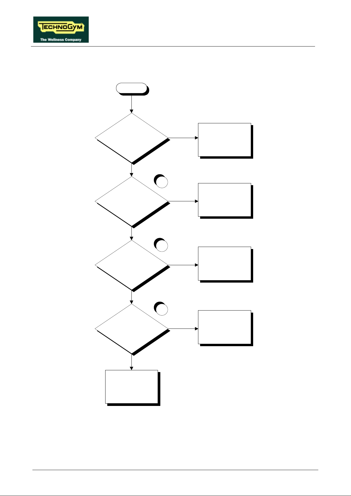
6.3.4. THE INVERTER DISPLAY SHOWS E9
This inverter error message is related to low line voltage problems on the inverter power supply.
E9
Does the machine resume
correct operation after being
turned off for 1 minute?
NO
Is the power supply at the
inverter input OK?
NO
Is the supply voltage at the
filter input correct?
YES
YES
Probable low line voltage.
The machine is OK
1
YES
Replace the inverter: see
paragraph 7.13.
2
NO
Check and reinstate the
wiring between the power
input socket, automatic
circuit breaker and filter
3
NO
Is the supply voltage at the
filter output correct?
Replace the filter
YES
Check and reinstate the
wiring between the filter
and inverter
Follow the procedure step by step to correctly diagnose the problem. Take particular care with the
checks highlighted by circled numbers, which are described in detail below:
(1) Place the tester probes between terminals L1 and N of the inverter. The measured voltage
should be 220 Vac or 110 Vac depending on the type of mains electricity supply.
Page 6.14
Page 45

RUN XT: Service & Maintenance Manual - rev. 2.0
(2) Disconnect the filter power supply cables and place the tester probes on the terminals. The
measured voltage should be 220 Vac or 110 Vac depending on the type of mains electricity
supply.
(3) Disconnect the filter output cables and place the tester probes across the filter terminals. The
measured voltage should be 220 Vac or 110 Vac depending on the type of mains electricity
supply.
This error may be generated even by brief drops in the line voltage due to overloads or
other causes. Therefore, it can be very useful to check the value of the mains voltage
recorded in the inverter memory at the time when the error occurred. To obtain the
mains voltage, the displayed value must be divided by 0.141 .
Page 6.15
Page 46
RUN XT: Service & Maintenance Manual - rev. 2.0
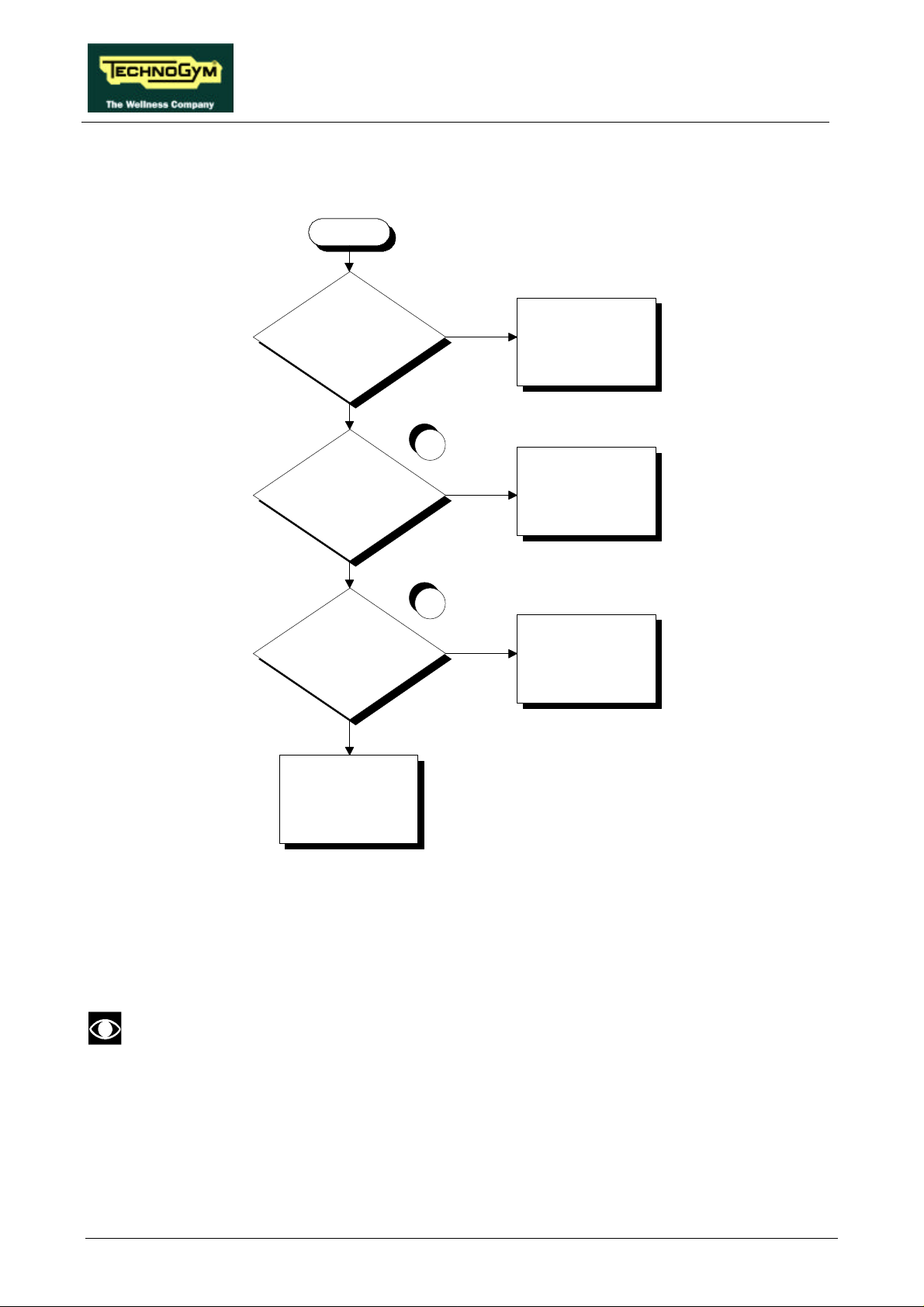
6.3.5. THE INVERTER DISPLAY SHOWS E12
This inverter error message is related to the opening of the motor thermal cutouts.
E12
YES
Does the machine resume
correct operation after being
turned off for 1 hour?
NO
1
NO
Is the thermal cutout on the
motor OK?
Probable overheating of
the motor. The machine is
OK
Replace the belt motor:
see paragraph 7.11
YES
2
Is the wiring between the
motor thermal cutout and
the inverter correct?
NO
Replace cable RX-5
YES
Replace the inverter: see
paragraph 7.13
Follow the procedure step by step to correctly diagnose the problem. Take particular care with the
checks highlighted by circled numbers, which are described in detail below:
(1) Disconnect the motor thermal cutout cables from the inverter and place the tester probes
between their terminals. The measured resistance should be less than 1 Ohm.
In some cases the value may be higher due to oxidation of the contacts. To reinstate
correct operation, it is necessary to perform a special operation which will be described
to you on contacting the Technogym Service.
(2) Disconnect the motor thermal cutout cables on both the motor and inverter sides, and place the
tester probes at either end of each wire. The measured resistance should be 0 Ohm.
Page 6.16
Page 47
RUN XT: Service & Maintenance Manual - rev. 2.0
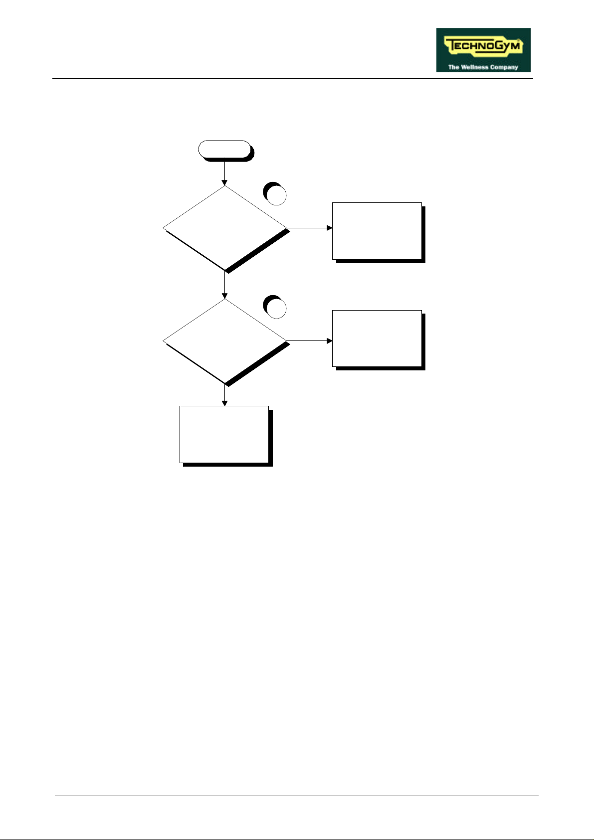
6.3.6. THE INVERTER DISPLAY SHOWS E14
This inverter error message is related to poor isolation between the motor phases and ground.
E14
1
Are the motor phases
isolated from ground at the
inverter output?
NO
Replace the inverter: see
paragraph 7.13
YES
2
NO
Are the motor phases
isolated from ground?
Replace the belt motor:
see paragraph 7.11.
YES
Check and reinstate cable
RX-14
Follow the procedure step by step to correctly diagnose the problem. Take particular care with the
checks highlighted by circled numbers, which are described in detail below:
(1) Disconnect the motor cable from the inverter and place the tester probes between terminals U,
V and W of the inverter and the ground screw (PE). The measured resistance should be MOhm
or higher.
(2) Disconnect the motor cable from the motor and place the tester probes between its terminals
U, V and W and ground. The measured resistance should be MOhm or higher.
Page 6.17
Page 48
RUN XT: Service & Maintenance Manual - rev. 2.0
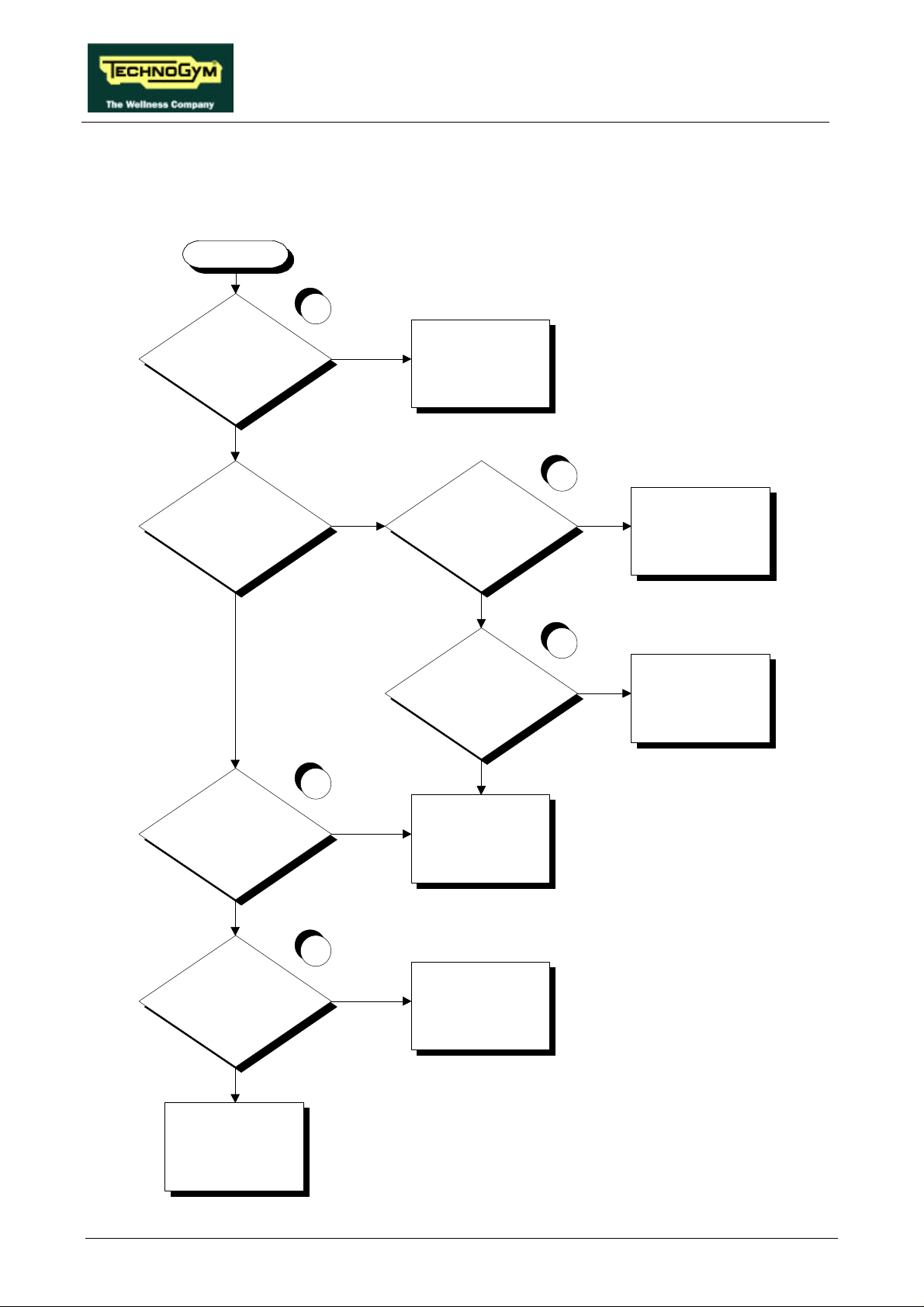
6.3.7. THE INVERTER DISPLAY DOES NOT SHOW ANY ERROR
This is an anomalous error condition in which the machine display reports an error but the inverter
has not generated an error.
None
1
Is the SW version up to
date?
YES
Is LED DL2 on the inverter
interface board illuminated?
YES
NO
Update the SW version
2
NO
Is the alarm signal present
at the inverter output?
YES
Replace the inverter: see
paragraph 7.13.
NO
3
YES
Is the alarm signal present
at the input to the inverter
interface board?
4
NO
Check and/or replace cable
RX-5 connecting the
inverter interface board to
the inverter
Page 6.18
Is the alarm present at the
output of the interface
board?
NO
Is the alarm present at the
input to the display?
NO
Replace the CPU board:
see paragraph 7.3.
YES
Replace the inverter
interface board: see
paragraph 7.12.
5
YES
Check and/or replace cable
RX-1 which connects the
inverter interface board to
the CPU board
Page 49

RUN XT: Service & Maintenance Manual - rev. 2.0
Follow the procedure step by step to correctly diagnose the problem. Take particular care with the
checks highlighted by circled numbers, which are described in detail below:
(1) The SW version must be higher than EUR 2.4, USA 2.3, TGS EUR 2.2 or TGS USA 2.3.
(2) Place the tester probes between terminals AL0 and AL1 of the inverter. Under an alarm
condition the measured voltage should be 0 Vdc, under normal conditions it should be +10
Vdc.
(3) As for point (2) but between pins 3 (signal) and 4 (ground) of connector CN1 on the inverter
interface board.
(4) Place the tester probes between pins 3 (ground) and 9 (signal) of connector CN2 on the
inverter interface board. Under an alarm condition the measured voltage should be 0 Vdc,
under normal conditions it should be +5 Vdc.
(5) As for point (4) but between pins 3 (ground) and 8 (signal) of connector CN1 on the CPU
board.
Page 6.19
Page 50
RUN XT: Service & Maintenance Manual - rev. 2.0
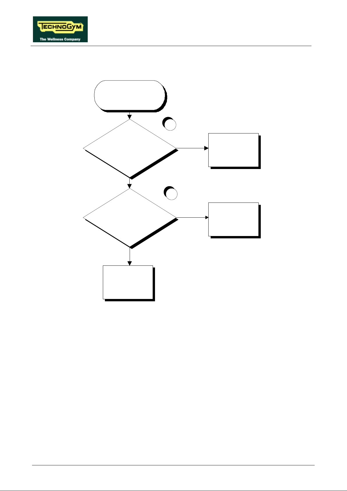
6.4. THE BELT MOTOR IS JERKING
THE BELT
MOTOR IS
JERKING
1
YES
Are the belt motor windings
short-circuited or open-circuited
NO
2
Replace the belt motor:
see paragraph 7.11.
Does the inverter generate a
balanced voltage on all phases?
NO
Replace the inverter: see
paragraph 7.12.
YES
Check and/or replace
cable RX-14 connecting
the inverter to the belt
motor
Follow the procedure step by step to correctly diagnose the problem. Take particular care with the
checks highlighted by circled numbers, which are described in detail below:
(1) Disconnect the motor cable from the motor and place a tester across its terminals U-V, U-W
and V-W. The measured resistance should be approximately 3.1 Ohm.
(2) Run the machine at 12.6 Km/h (European version) or 9.0 mph (USA version) and place a
tester across its terminals U-V, U-W and V-W. The measured voltage should be 220 Vac.
Page 6.20
Page 51
RUN XT: Service & Maintenance Manual - rev. 2.0
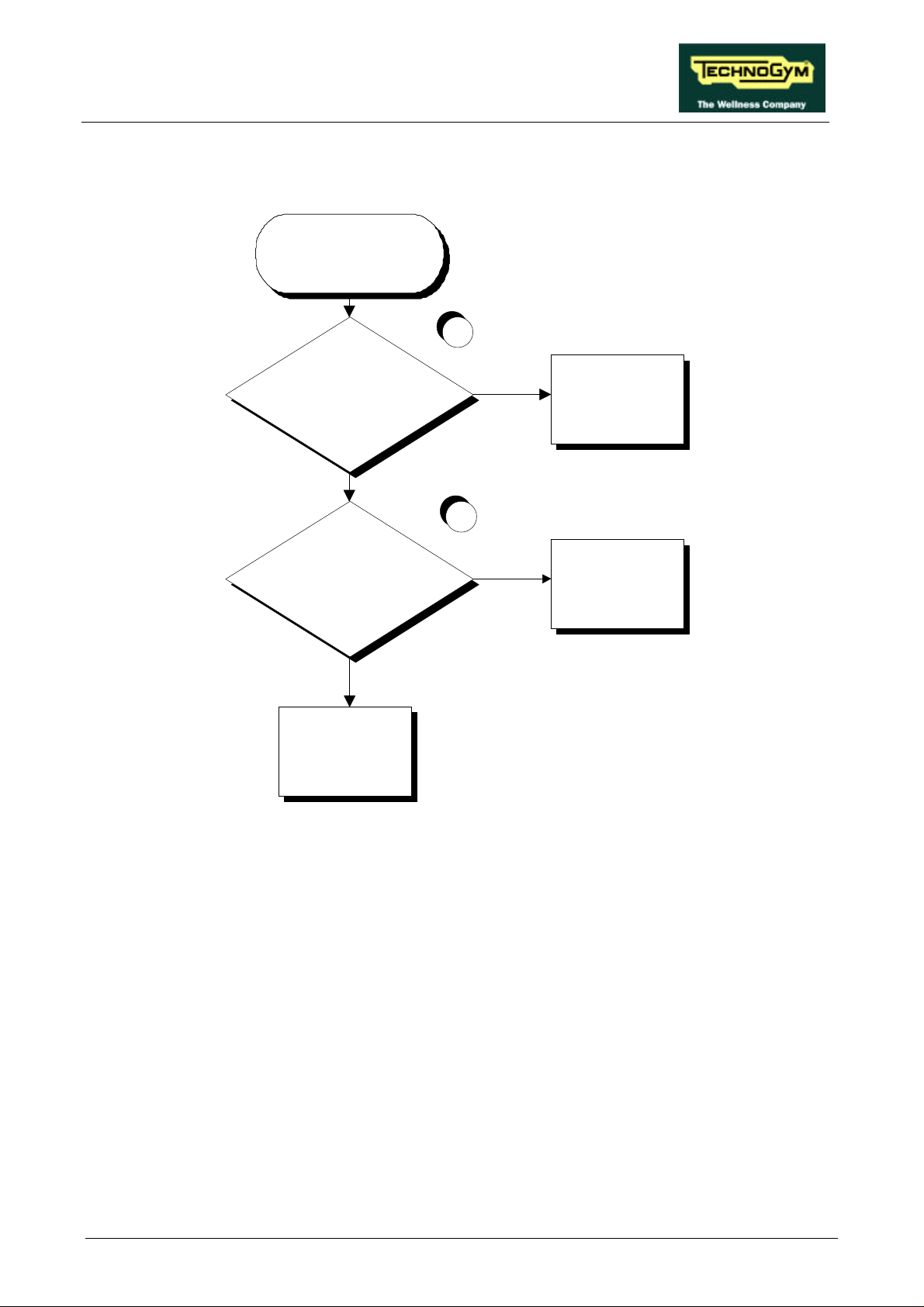
6.5. THE BELT MOTOR STARTS WITH DELAY
THE BELT
MOTOR STARTS
WITH DELAY
1
Are the Start and Speed PWM
signals correct at the output of the
CPU board?
YES
Are the Start signal and the analog
speed reference signal correct at the
output of the inverter interface
board?
YES
Replace the inverter: see
paragraph 7.13.
NO
Replace the CPU board:
see paragraph 7.3.
2
NO
Replace the inverter
interface board: see
paragraph 7.12.
Follow the procedure step by step to correctly diagnose the problem. Take particular care with the
checks highlighted by circled numbers, which are described in detail below:
(1) To check the Start signal, place a tester between pins 7 (signal) and 3 (ground) of connector
CN1 on the CPU board. When the belt is halted the measured voltage should be 0 Vdc,
whereas immediately after pressing the “Start” key on the display the measured voltage should
be 4.5 Vdc. To check the speed PWM signal, place a tester between pins 6 (signal) and 3
(ground) of connector CN1 on the CPU board. When the belt is halted the measured voltage
should be 5 Vdc, whereas immediately after pressing the “Start” key on the display the reading
should rapidly decrease until it reaches a fixed value corresponding to the selected speed. The
variation of the signal must be accompanied by a corresponding variation in the tread belt
speed: see Table 6.6-1 or Table 6.6-2.
(2) To check the Start signal, place a tester between pins 2 (signal) and 1 (ground) of connector
CN1 on the inverter interface board. When the belt is halted the reading should be -24.7 Vdc,
whereas immediately after pressing the “Start” key on the display the measured value should be
-2.7 Vdc. To check the speed PWM signal, place a tester between pins 5 (signal) and 6
Page 6.21
Page 52

RUN XT: Service & Maintenance Manual - rev. 2.0
(ground) of connector CN1 on the inverter interface board. When the belt is halted the
measured value should be 0 Vdc, whereas immediately after pressing the “Start” key on the
display the reading should rapidly increase to reach a fixed value corresponding to the selected
speed. The variation of the signal must be accompanied by a corresponding variation in the belt
speed: see Table 6.6-1 or Table 6.6-2.
Page 6.22
Page 53

RUN XT: Service & Maintenance Manual - rev. 2.0
6.6. THE DISPLAYED SPEED IS INCORRECT
THE DISPLAYED SPEED
IS INCORRECT
1
Is the relationship between the
displayed speed and the inverter
frequency correct?
NO
Is the inverter control voltage
correct?
NO
Is the inverter control voltage at the
output of the inverter interface board
correct?
YES
The machine is operating
correctly
YES
2
3
Replace the inverter: see
paragraph 7.13.
YES
Is the inverter programmed
correctly?
Re-program the inverter:
4
YES
Check and/or replace
cable RX-5 between the
inverter interface board
and the inverter
NO
see paragraph 9.1.
NO
Is the inverter control PWM signal at
the input of the inverter interface
board correct?
NO
A
Continued on the following page.
5
YES
Replace the inverter
interface board: see
paragraph 7.12.
Page 6.23
Page 54
RUN XT: Service & Maintenance Manual - rev. 2.0
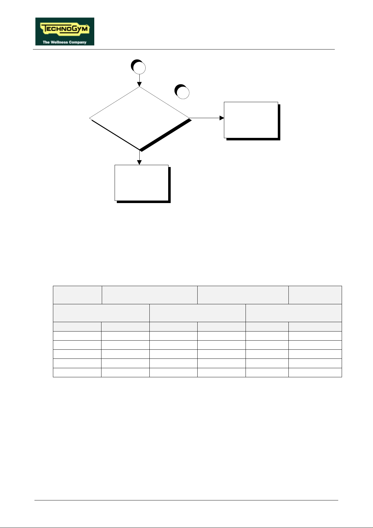
A
6
Is the inverter control PWM signal at
the output of the CPU board correct?
NO
Replace the CPU board:
see paragraph 7.3.
YES
Check and/or replace
cable RX-1 connecting
the CPU board and the
inverter interface board
Follow the procedure step by step to correctly diagnose the problem. Take particular care with the
checks highlighted by circled numbers, which are described in detail below:
(1) When the machine is in operation, check that the speed shown on the machine display and
inverter operating frequency correspond to the values shown in the tables below.
• For versions with speed expressed in km/h:
SPEED
(Km/h)
CPU BOARD INVERTER
PWM SIGNAL
(Vdc)
ANALOG SIGNAL
(Vdc)
FREQUENCY
(Hz)
INVERTER
INTERFACE BOARD
DISPLAY 6-3/CN1 10-3/CN2 5-6/CN1 L-0 DISPLAY
2.0 4.40 4.40 1.08 1.08 11.2
5.0 3.53 3.53 2.68 2.68 27.5
9.0 2.38 2.38 4.82 4.82 49.3
12.6 1.34 1.34 6.75 6.75 69.0
16.0 0.35 0.35 8.57 8.57 87.6
Table 6.6-1
Page 6.24
Page 55
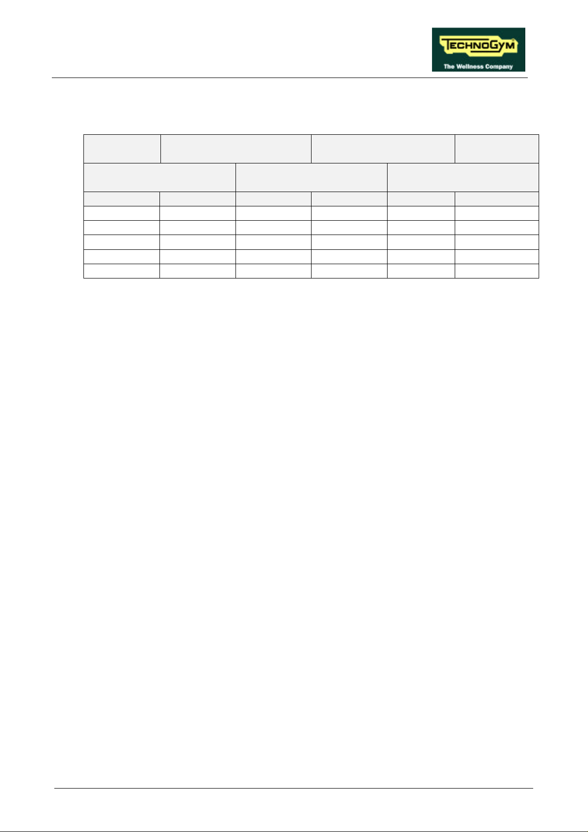
RUN XT: Service & Maintenance Manual - rev. 2.0
• For versions with the speed expressed in mph:
SPEED
(mph)
CPU BOARD INVERTER
PWM SIGNAL
(Vdc)
ANALOG SIGNAL
(Vdc)
FREQUENCY
(Hz)
INVERTER
INTERFACE BOARD
DISPLAY 6-3/CN1 10-3/CN2 5-6/CN1 L-0 DISPLAY
1.0 4.56 4.56 0.87 0.87 9.0
3.0 3.62 3.62 2.60 2.60 26.5
5.0 2.70 2.70 4.32 4.32 44.1
7.0 1.75 1.75 6.06 6.06 61.7
9.0 0.81 0.81 7.78 7.78 79.3
Table 6.6-2
Obviously, the voltages and frequencies quoted above are nominal values.
(2) Place the tester probes between the terminals 0 (signal) and L (ground) of the inverter. Check
that during machine operation the speed shown on the display and the voltage measured on the
inverter correspond to the values shown in Table 6.6-1 or in Table 6.6-2.
(3) See paragraph 9.4.
(4) Place the tester probes between pins 5 (signal) and 6 (ground) of connector CN1 on the
inverter interface board. Check that during machine operation the speed shown on the display
and the measured voltage correspond to the values shown in Table 6.6-1 or in Table 6.6-2.
(5) Place the tester probes between pins 10 (signal) and 3 (ground) of connector CN2 of the
inverter interface board. Check that during machine operation the speed shown on the display
and the measured voltage correspond to the values shown in Table 6.6-1 or Table 6.6-2.
(6) Place the tester probes between pins 6 (signal) and 3 (ground) of connector CN1 on the CPU
board. Check that during machine operation the speed shown on the display and the measured
voltage correspond to the values shown in Table 6.6-1 or in Table 6.6-2.
Page 6.25
Page 56
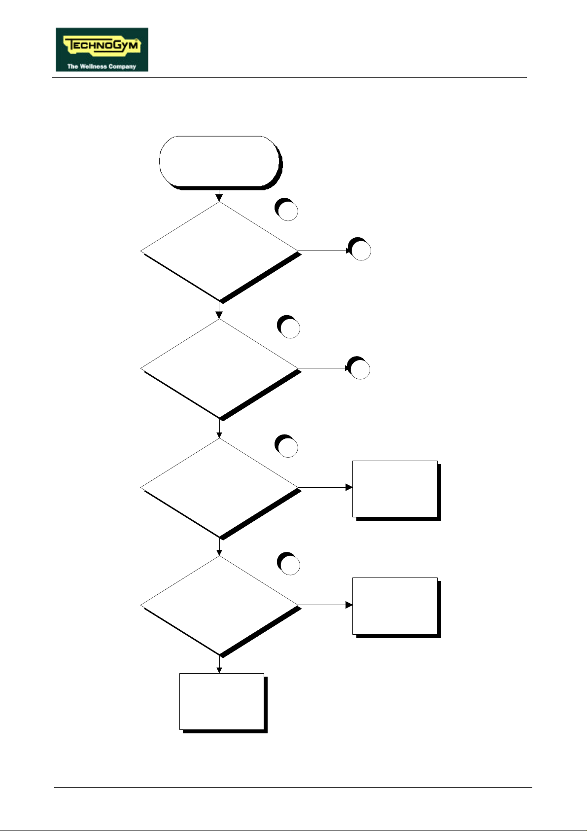
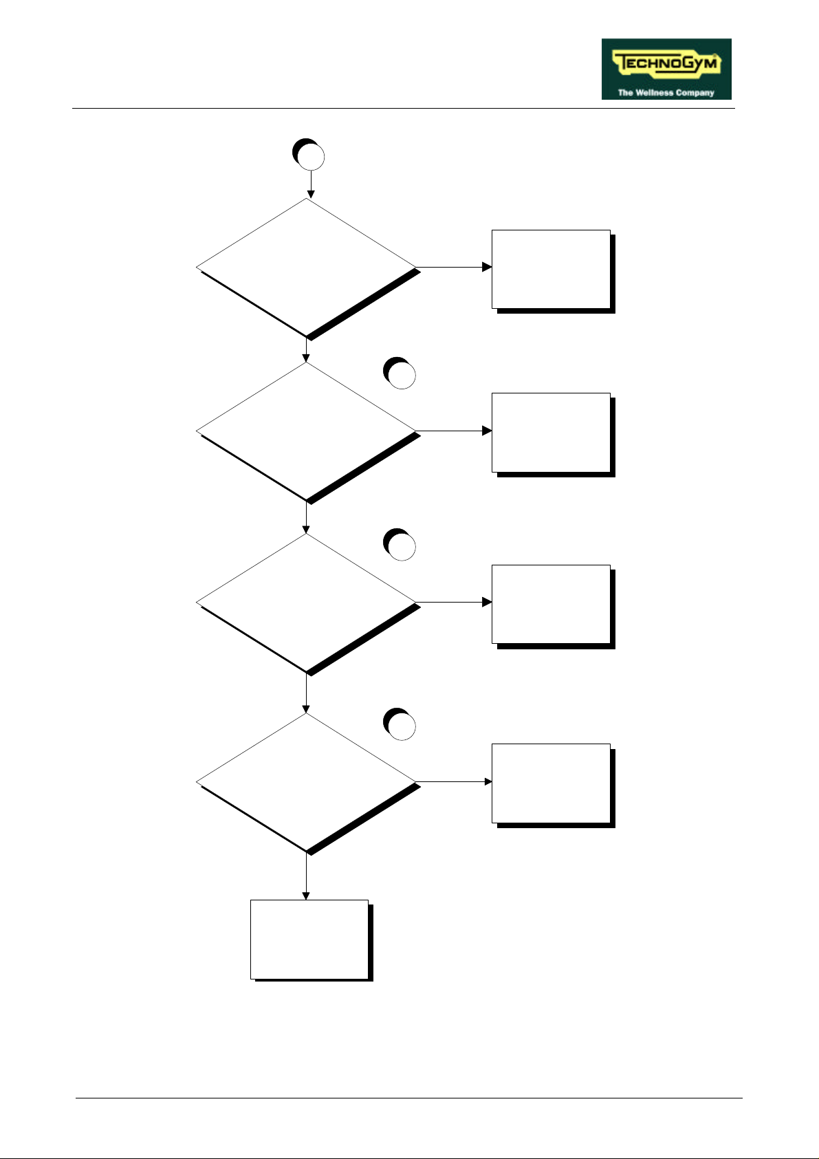
6.7. THE DISPLAY SHOWS “E5”
THE DISPLAY
SHOWS "E5"
1
Are LEDs DL1 and DL2 on the
up-down board both illuminated?
YES
2
RUN XT: Service & Maintenance Manual - rev. 2.0
NO
A
Is the supply to the up-down motor
correct when the actuation command
arrives?
NO
Does the CPU board send the
correct control signal?
YES
Does the up-down board receive the
correct control signal?
YES
B
3
NO
Replace the CPU board:
see paragraph 7.3.
4
NO
Check and/or replace
cable RX-1 connecting
the CPU board to the
up-down board
Replace the up-down
board: see paragraph
Continued on the following page.
Page 6.26
YES
7.12.
Page 57
RUN XT: Service & Maintenance Manual - rev. 2.0
A
NO
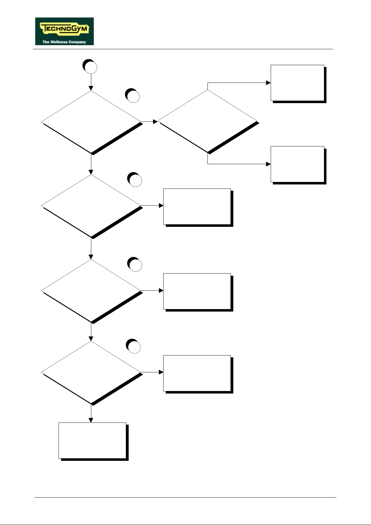
Is fuse F1 of the up-down board OK?
YES
Does the up-down board receive the
mains electricity supply?
YES
Does the voltage at output by the
transformer-rectifier reach the
up-down board?
Replace the fuse
5
NO
Check and/or replace the
cable connecting the
up-down board to the
filter
6
YES
Replace the up-down
board: see paragraph
7.12.
Is the voltage at the transformer
output correct?
Replace the transformer:
see paragraph 7.12.
Continued on the following page.
NO
NO
7
YES
Replace the rectifier
bridge: see paragraph
7.12.
Page 6.27
Page 58
RUN XT: Service & Maintenance Manual - rev. 2.0
B
Is the up-down motor current
correct?
YES
Is the pulse signal at the photocell
output correct?
NO
Lubricate the elevation
bars
8
NO
Are the elevation bars lubricated?
Replace the up-down
motor: see paragraph
YES
7.15.
9
NO
Replace the photocell: see
paragraph 7.20.
YES
Does the up-down board output the
status signal?
YES
Does the status signal reach the
CPU board?
YES
10
11
NO
Replace the up-down board: see
paragraph 7.12.
NO
Check and/or replace cable RX-1
connecting the CPU board to the
up-down board
Page 6.28
Replace the CPU board: see
paragraph 7.3.
Page 59

RUN XT: Service & Maintenance Manual - rev. 2.0
Follow the procedure step by step to correctly diagnose the problem. In particular, carry out the
checks described in the flowchart with the machine at an elevation between 0 and +15%.
If the motor momentarily starts and stops immediately afterward, there is probably a
problem with the photocell or its cable.
If the machine is locked in one of its travel limit positions, the corresponding limit switch
will be tripped, and therefore the machine will be able to move in only one direction. If
movement in this direction is impeded due to a problem, the message E5 may appear on
the display.
Take particular care with the checks highlighted by circled numbers, which are described in detail
below:
(1) Each LED corresponds to a limit switch. DL1 turns off when the upper limit switch is tripped,
while DL3 turns off when the lower limit switch is tripped. If neither of the 2 limit switches is
tripped and one of the 2 LEDs is off, refer to paragraph 6.8. “The up-down moves in only one
direction”.
(2) Place the tester probes between pins 1 and 2 of connector CN3 on the up-down board. When
the “↑” or “↓” key is pressed the measured value should be approximately 48 Vdc.
(3) Place the tester probes between pins 12 (ground) and 11 (signal) of connector CN1 on the
CPU board. When the “↓” key is pressed the measured value should be approximately 5 Vdc.
Place the tester probes between pins 12 (ground) and 10 (signal) of connector CN1 of the CPU
board. When the “↑” key is pressed the measured voltage should be approximately 5 Vdc.
(4) Place the tester probes between pins 4 (ground) and 3 (signal) of connector CN2 on the up-
down. board. When the “↓” key is pressed the measured voltage should be approximately 5
Vdc. Place the tester probes between pins 4 (ground) and 2 (signal) of connector CN2 on the
up-down board. When the “↑” key is pressed the measured voltage should be approximately 5
Vdc.
(5) Place the tester probes between pins 1 and 2 of connector CN4 on the up-down board. The
measured voltage should be approximately 220 Vac or 110 Vac depending on the type of
mains electricity supply.
(6) Place the tester probes between pins 1 and 2 of connector CN6 on the up-down board. The
measured voltage should be approximately 50 Vdc.
(7) Disconnect the yellow transformer cables on the rectifier bridge and place the tester probes
across the 2 terminals. The measured voltage should be 38 Vac.
(8) Place the tester probes in series with the motor cable. When the “↑” or “↓” key is pressed the
measured steady-state current should be less than 6 A. To correctly carry out the measurement
procedure refer to 11.3.3. “AC and DC current”.
Page 6.29
Page 60

RUN XT: Service & Maintenance Manual - rev. 2.0
(9) Slightly lift the connector on the photocell and place the tester probes between pins 4 (ground)
and 2 (signal). When the motor moves, the tester should detect the pulses generated by the
photocell.
(10) Place the tester probes between pins 4 (ground) and 1 (signal) of connector CN2 on the up-
down. board. When the motor moves, there should be one pulse for each ½ degree change in
the machine elevation.
(11) As for step (10), but with the tester probes between pins 12 (ground) and 9 (signal) of
connector CN1 on the CPU board.
Page 6.30
Page 61
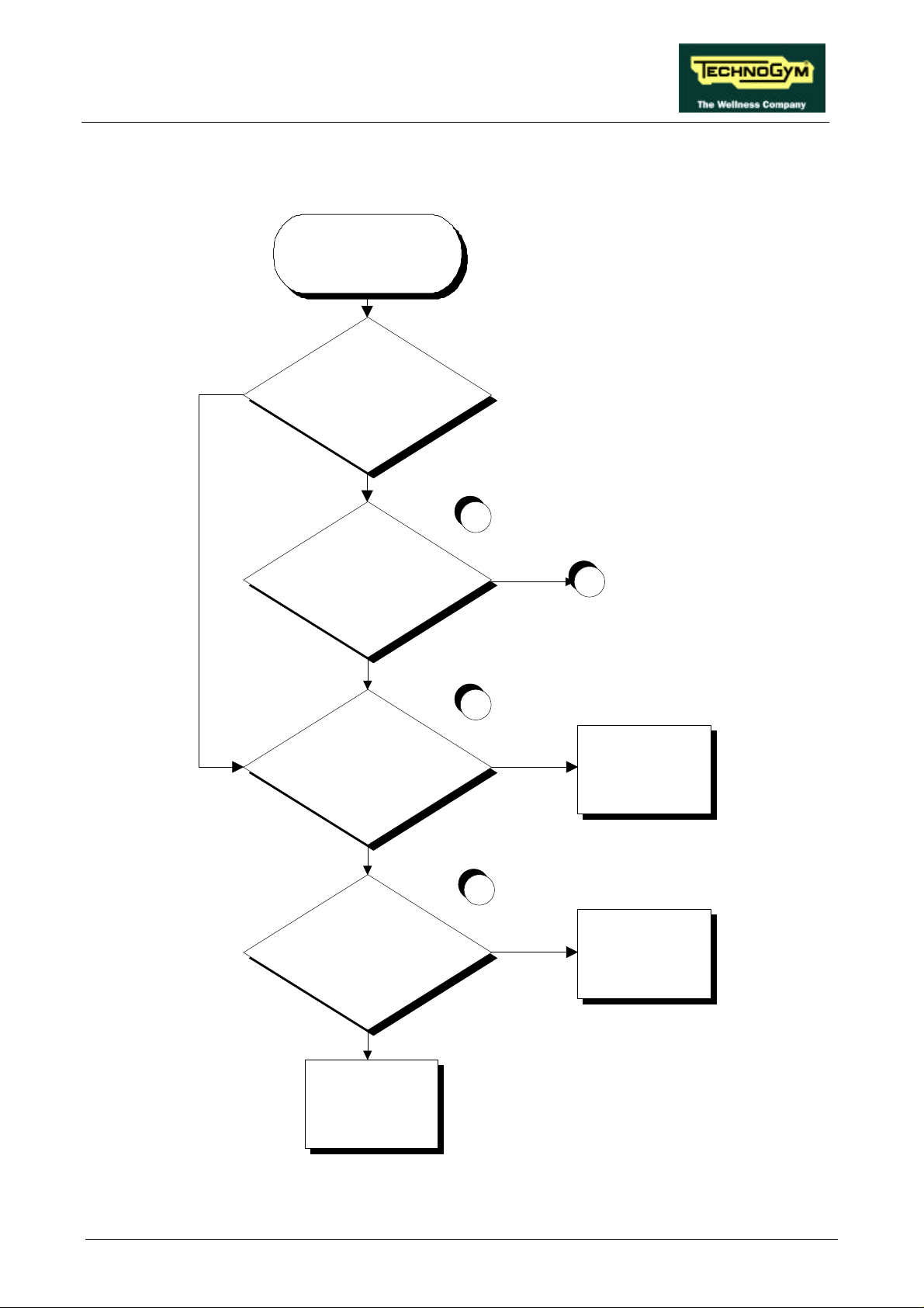
RUN XT: Service & Maintenance Manual - rev. 2.0
6.8. THE UP-DOWN MOVES IN ONLY ONE DIRECTION
THE UP-DOWN
MOVES IN ONLY
ONE DIRECTION
YES
Are LEDs DL1 and DL3 on the
up-down board both illuminated?
NO
1
Is the machine in one of the 2 travel
limit poYEStions?
YES
Does the up-down board receive the
correct control YESgnal in the
inactive direction?
NO
Does the CPU board send the
correct control YESgnal in the
inactive direction?
NO
A
2
YES
Replace the up-down
board: see paragraph
7.15
3
YES
Check and/or replace
cable RX-1 connecting
the CPU board to the
up-down board
Replace the CPU board:
Continued on the following page.
NO
see paragraph 7.3.
Page 6.31
Page 62
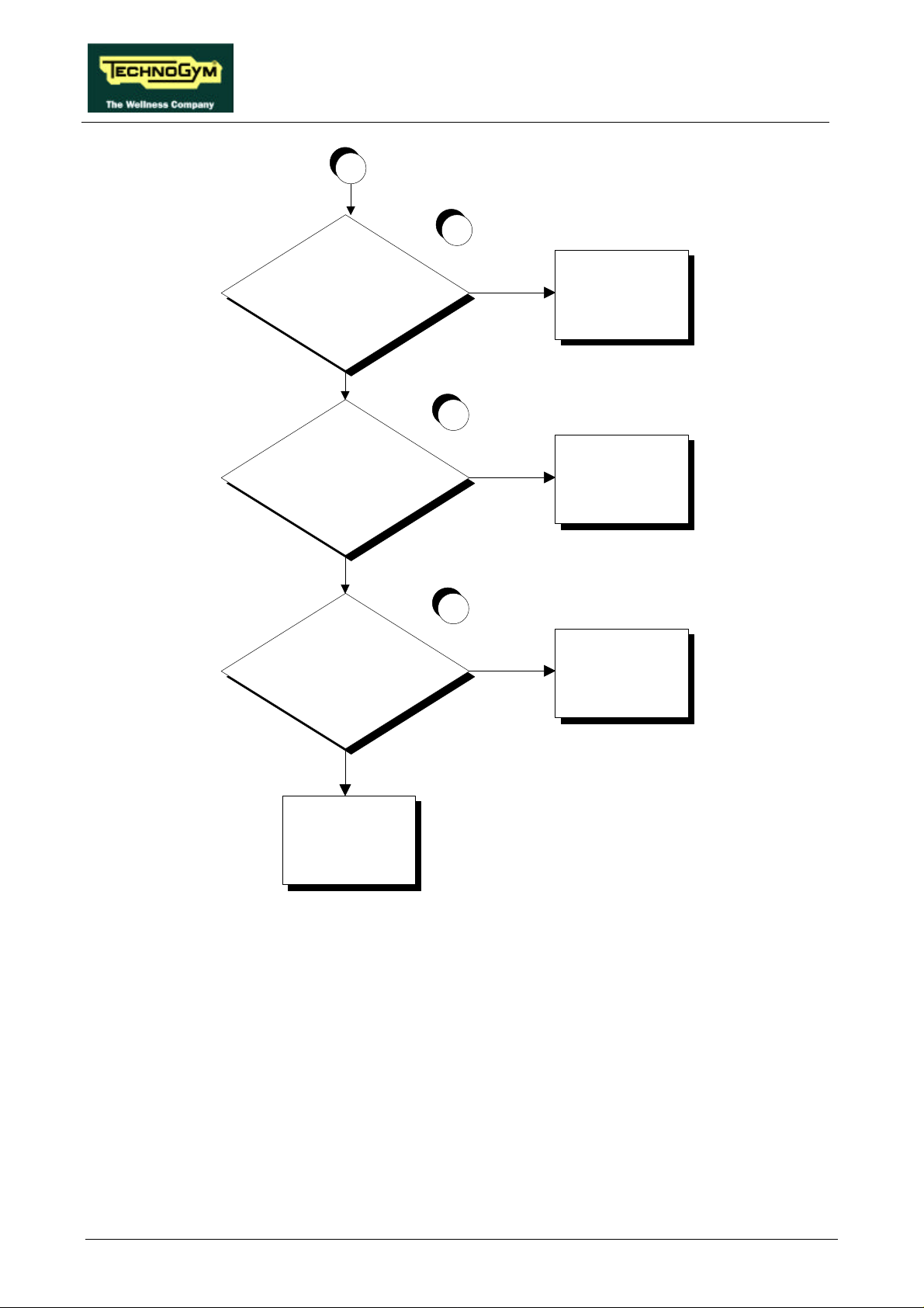
A
Is the limit switch associated with the
non-illuminated LED tripped?
NO
RUN XT: Service & Maintenance Manual - rev. 2.0
4
YES
Check the position and/or
replace the limit switch:
see paragraph 7.19.
5
Is the power supply to the limit
switch associated with the
non-illuminated LED correct?
NO
Does the up-down board send the
correct power supply to the limit
switch associated with the
non-illuminated LED?
NO
Replace the up-down
board: see paragraph
7.12.
YES
Replace the limit switch:
see paragraph 7.19.
6
YES
Check and/or replace
cable RX-6 connecting
the up-down board to the
limit switches
Follow the procedure step by step to correctly diagnose the problem. Take particular care with the
checks highlighted by circled numbers, which are described in detail below:
(1) The machine is considered to have reached a travel limit when the corresponding limit switch is
tripped. The lower limit switch is tripped when its lever is pressed, while the upper limit switch
is tripped when its lever is released.
(2) If the machine fails to move downward, place the tester probes between pins 4 (ground) and 3
(signal) of connector CN2 on the up-down board: the measured voltage should be
approximately 5 Vdc. If the machine fails to move upward, place the tester probes between
pins 4 (ground) and 2 (signal) of connector CN2 on the up-down board: the measured voltage
should be approximately 5 Vdc.
Page 6.32
Page 63

RUN XT: Service & Maintenance Manual - rev. 2.0
(3) If the machine fails to move downward, place the tester probes between pins 12 (ground) and
11 (signal) of connector CN1 on the CPU board: the measured voltage should be
approximately 5 Vdc. If the machine fails to move upward, place the tester probes between
pins 12 (ground) and 10 (signal) of connector CN1 on the CPU board: the measured voltage
should be approximately 5 Vdc.
(4) DL1 corresponds to the upper limit switch, while DL3 corresponds to the lower limit switch.
(5) Disconnect the 2 connecting cables of the relevant limit switch and place the tester probes
across them: the measured voltage should be approximately 12 Vdc.
(6) To check the upper limit switch, place the tester probes between pins 6 (ground) and 3 (signal)
of connector CN3 on the up-down board.: the measured voltage should be 12 Vdc. To check
the lower limit switch, place the tester probes between pins 6 (ground) and 4 (signal) of
connector CN3 on the up-down board: the measured voltage should be 12 Vdc.
Page 6.33
Page 64
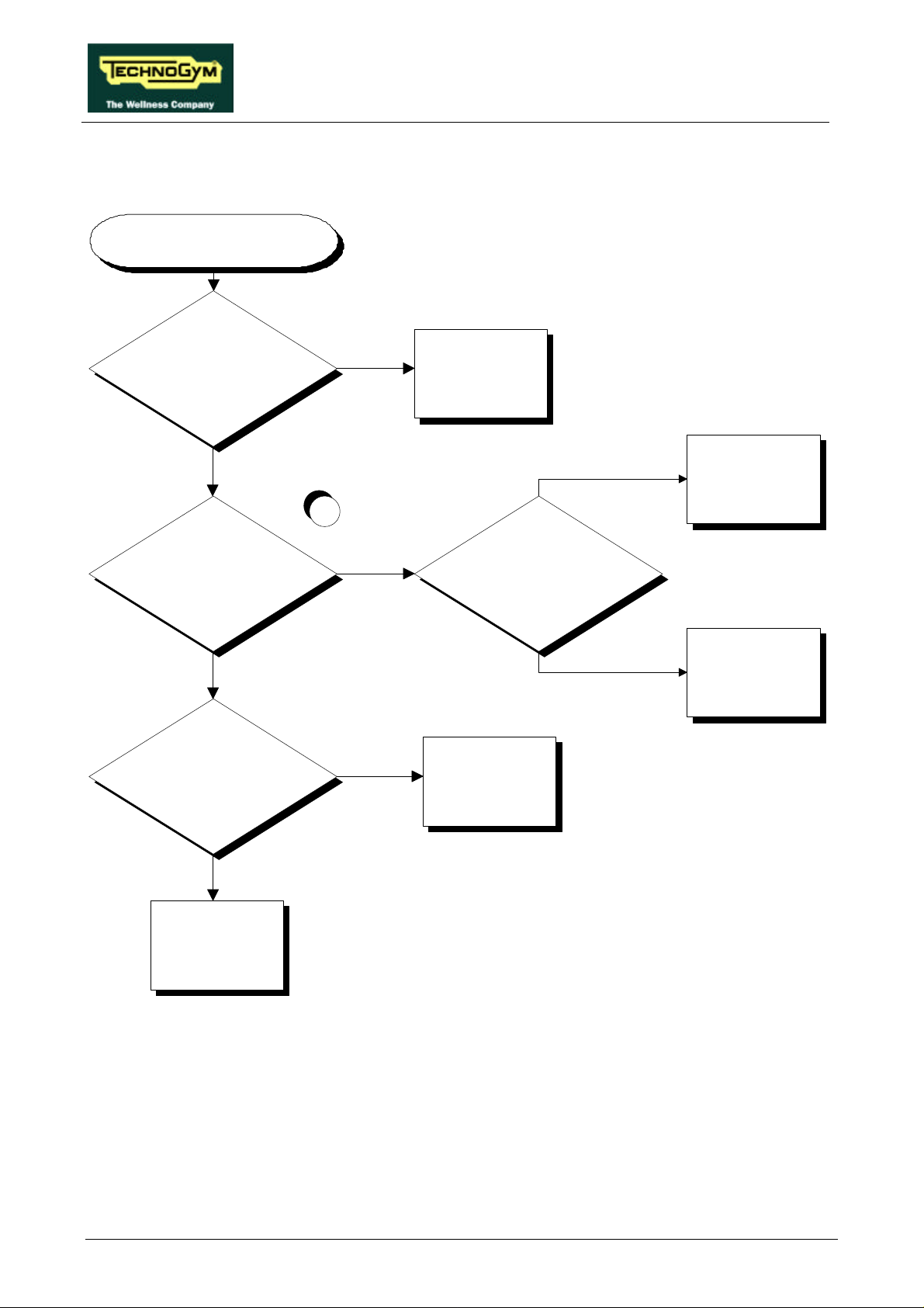
RUN XT: Service & Maintenance Manual - rev. 2.0
6.9. THE DISPLAYED ELEVATION IS INCORRECT
THE DISPLAYED
ELEVATION IS INCORRECT
NO
Is the position of the limit switch
correct?
Adjust the position of the
limit switch
YES
Is the up-down motor current
correct?
YES
Is the photocell clean?
YES
NO
Lubricate the elevation
bars
1
NO
Are the elevation bars lubricated?
Replace the up-down
motor: see paragraph
YES
7.15.
NO
Clean the photocell
Replace the photocell and
cable RX-12 connecting
the up-down board and
the photocell: see
paragraph 7.20.
Follow the procedure step by step to correctly diagnose the problem. Take particular care with the
checks highlighted by circled numbers, which are described in detail below:
(1) Place the tester probes in series with the motor cable. When the “↑” or “↓” keys are pressed
the measured steady-state current should be less than 6 A. To correctly carry out the
measurement procedure refer to 11.3.3. “AC and DC current”.
Page 6.34
Page 65
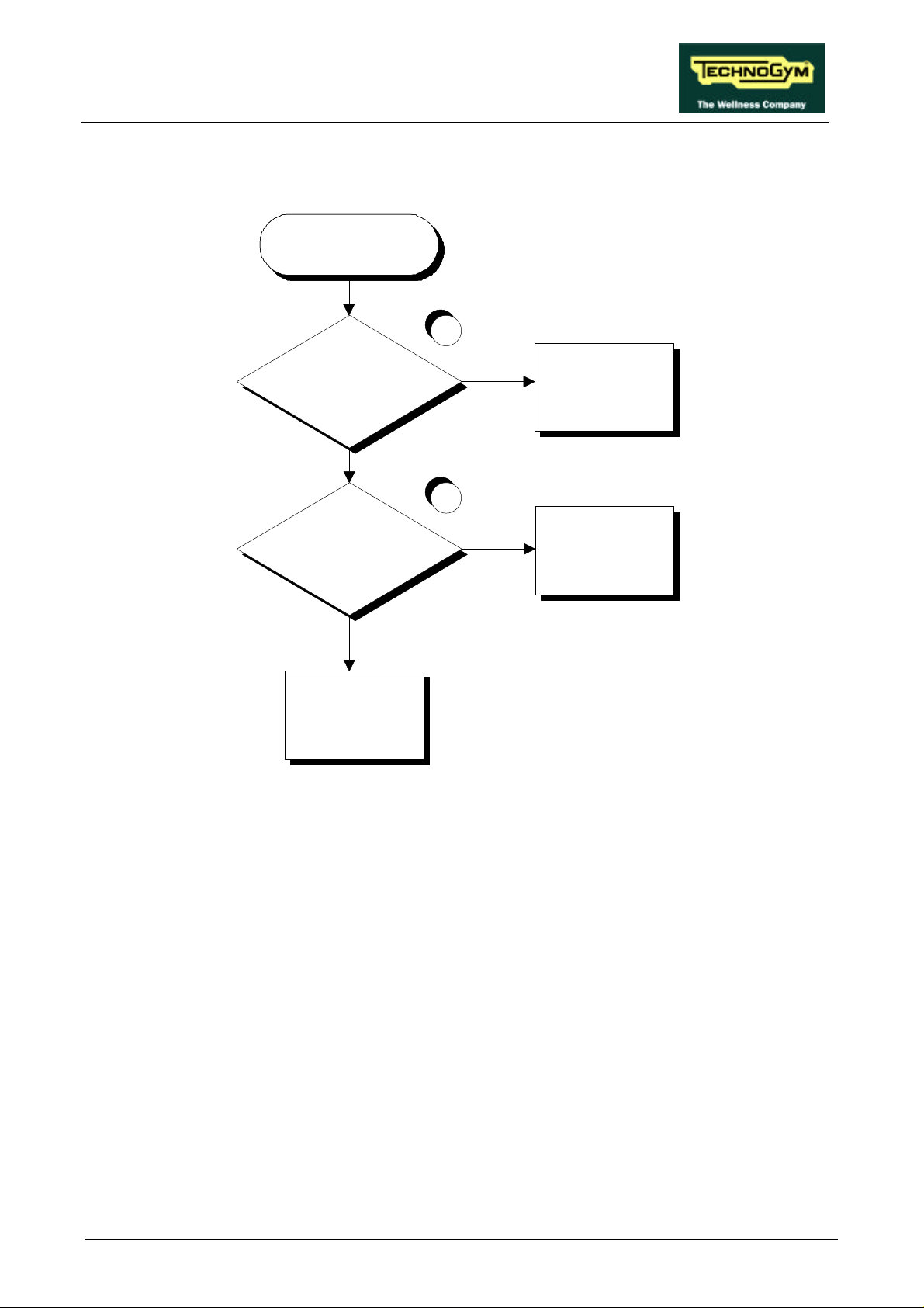
RUN XT: Service & Maintenance Manual - rev. 2.0
6.10. THERE IS NO HEART RATE SIGNAL
THERE IS NO
CARDIO SIGNAL
1
Is the supply voltage on the
receiver connector correct?
YES
Replace the receiver: see
paragraph 7.5.
NO
2
Is the supply voltage on
connector CN4 of the CPU board
correct.
YES
Replace or repair cable
BK-7: see paragraph 7.5.
NO
Replace the display CPU
board: see paragraph 7.3.
Follow the procedure step by step to correctly diagnose the problem. Take particular care with the
checks highlighted by circled numbers, which are described in detail below:
(1) Place the tester probes between pins 1 (signal) and 3 (ground) (corresponding to the red and
black wires) of the 4-pin receiver connector: the measured voltage should be +5Vdc.
(2) Place the tester probes between pins 1 (signal) and 3 (ground) (corresponding to the red and
black wires) of connector CN4 on the CPU board of the display: the measured voltage should
be +5Vdc.
Page 6.35
Page 66
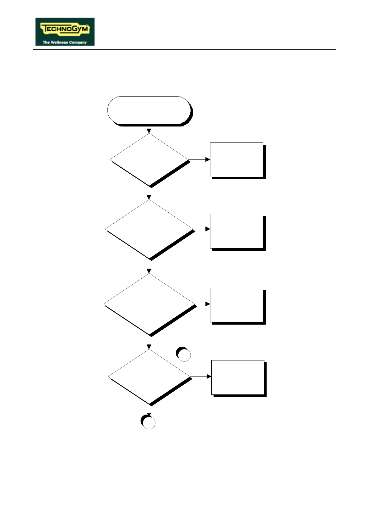
RUN XT: Service & Maintenance Manual - rev. 2.0
6.11. THE HEART RATE SIGNAL IS INCORRECT
In some case the machine may show “Err” on the heart rate display.
THE HEART RATE
SIGNAL IS
INCORRECT
Is the minimum distance
between machines OK?
YES
Is the receiver positioned
correctly, and are the
connecting cables correctly
routed?
YES
If the TGS is present, is the
TGSRN2ST cable correctly
routed?
NO
Move the machines to
the minimum distance:
see paragraph 5.1.
NO
Position the receiver and
the cable correctly: see
paragraph 11.1
NO
Correctly route the cable:
see paragraph 11.1.
Are there sources of
electromagnetic noise near
Continued on the following page.
Page 6.36
YES
the receiver?
NO
A
1
Move the machine away
YES
from the electromagnetic
source or attenuate the
power of the noise: see
paragraph 11.1.
Page 67
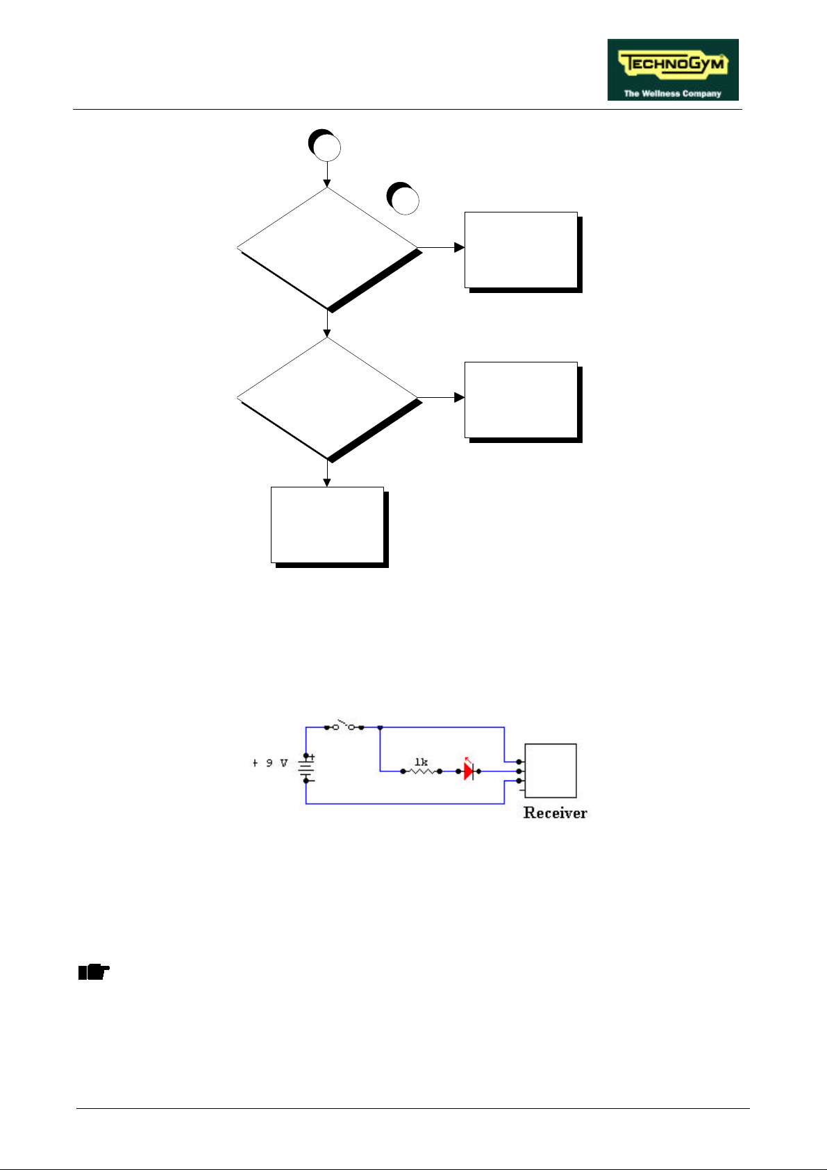
RUN XT: Service & Maintenance Manual - rev. 2.0
A
2
Is the transmitter in good
working order?
NO
Use a known good
transmitter
YES
Is the transmitter always
within a distance of 80 cm
from the receiver?
NO
Keep the transmitter
within the minimum
reception distance
YES
Change the receiver.
See paragraph 7.5.
Follow the procedure step by step to correctly diagnose the problem. Take particular care with the
checks highlighted by circled numbers, which are described in detail below:
(1) To check for electromagnetic noise near the machine, use a frequency signal monitor
constructed as shown in the schematic below:
The circuit lights the LED for every heart beat and/or disturbance that is received: in this way
it possible to determine whether there is any interference, and identify its sources.
(2) Check the battery power level, using a tester if possible. Otherwise use a receiver or another
“reference” machine to check operation up to a distance of about 80 cm from the receiver.
ATTENTION: Consult paragraph 11.1. “Technical notes on cardio receivers” in the
Appendix.
Page 6.37
Page 68

RUN XT: Service & Maintenance Manual - rev. 2.0
Page intentionally left blank
Page 6.38
Page 69
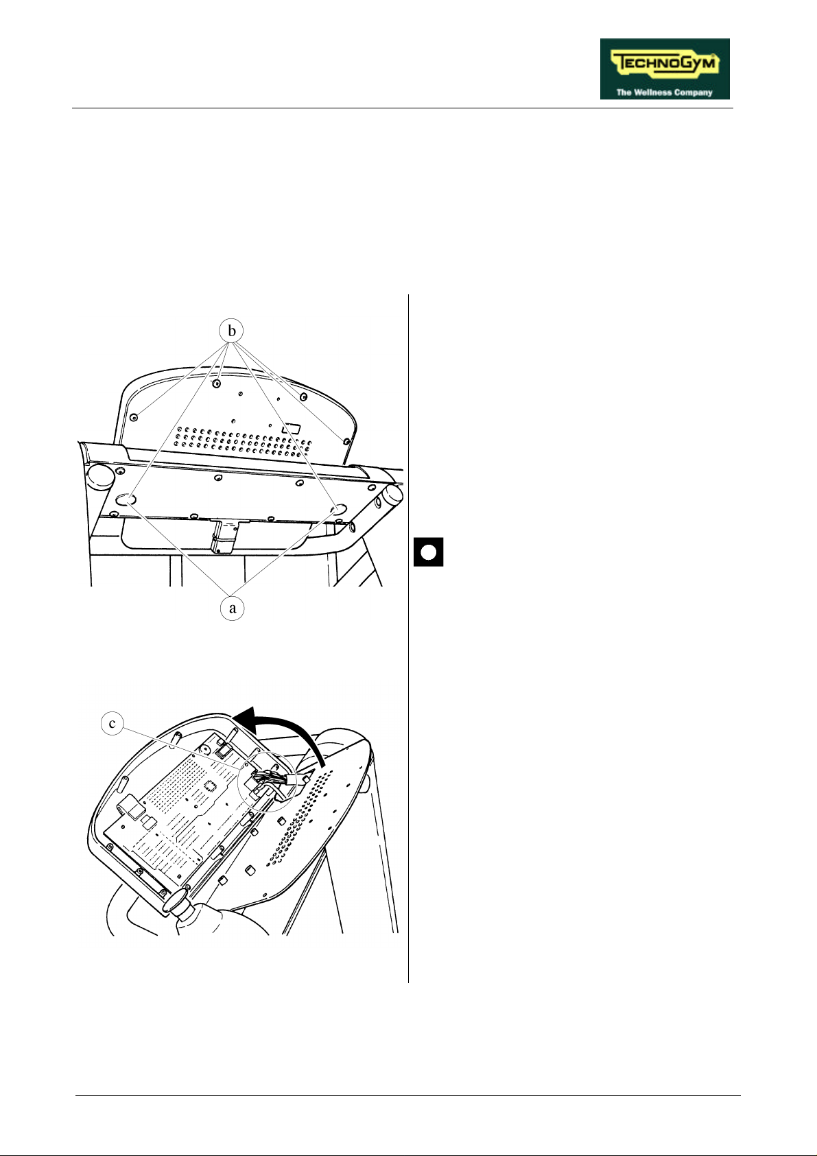
RUN XT: Service & Maintenance Manual - rev. 2.0
7. DISASSEMBLY OF COMPONENTS
7.1. DISASSEMBLING THE DISPLAY
1. Turn off the machine and unplug the mains
lead from the wall outlet.
2. Remove the 2 caps a.
Figure 7.1-1
3. Unscrew the 6 self-tapping screws b which
fix the DISPLAY, using a large Phillips
screwdriver.
Support the DISPLAY before removing
the last screw.
4. Open the DISPLAY.
To remove the DISPLAY:
1. Disconnect connectors c.
2. Remove the DISPLAY.
Figure 7.1-2
To reassemble the DISPLAY, carry out the
above steps in reverse order.
Page 7.1
Page 70
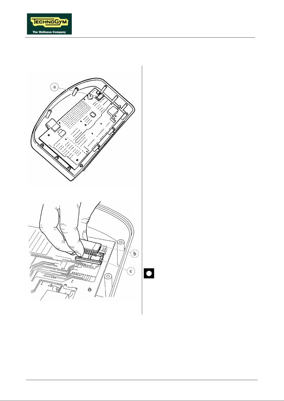
RUN XT: Service & Maintenance Manual - rev. 2.0
7.2. DISASSEMBLING THE EPROM
Carry out the procedure described in paragraph
7.1. “Disassembling the display”.
With the display on a work bench:
Remove EPROM a from its socket using an
integrated-circuit extractor tool.
Figure 7.2-1
Figure 7.2-2
To reassemble the EPROM:
1. Make sure that reference index b on the
EPROM coincides with reference notch c on
the socket.
2. Be careful to center the EPROM pins above
their corresponding holes in the socket.
3. Push the pins into the socket.
The EPROM can be irreversibly
damaged if the reference index on the
EPROM is not correctly aligned with
the notch on the socket, or if its pins are
bent.
Page 7.2
Page 71
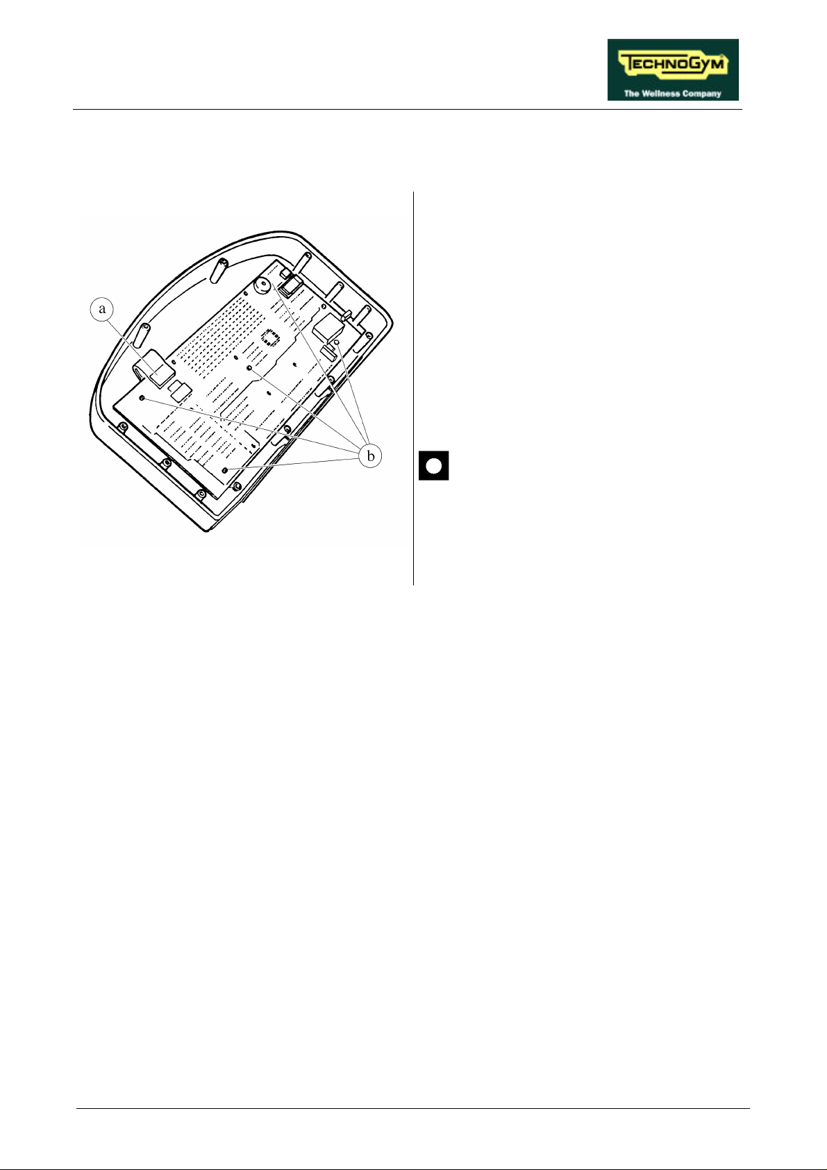
RUN XT: Service & Maintenance Manual - rev. 2.0
7.3. DISASSEMBLING THE CPU BOARD
Carry out the procedures described in paragraph
7.1. “Disassembling the display”.
With the display placed on a work bench:
1. Disconnect keyboard connector a.
2. Remove the 5 screws b, using a small Phillips
screwdriver.
3. Disconnect the cardio receiver if it is still
connected.
4. Remove the CPU board.
Figure 7.3-1
These procedures must be carried out on
a work bench.
To reassemble the CPU BOARD, carry out the
above steps in reverse order
Page 7.3
Page 72
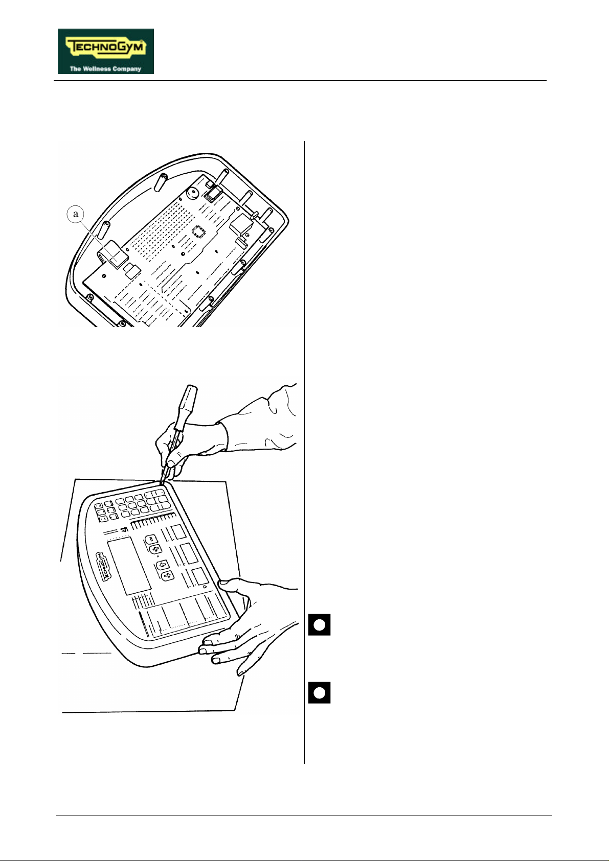
RUN XT: Service & Maintenance Manual - rev. 2.0
7.4. DISASSEMBLING THE KEYBOARD
Carry out the procedure described in paragraph
7.1. “Disassembling the display”.
1. Disconnect KEYBOARD connector a.
Figure 7.4-1
With the display placed on a work bench:
1. Use a sharp tool to lift up a corner of the
KEYBOARD and detach it.
To assemble the new KEYBOARD, with the
display on a work bench:
1. Remove the backing film which protects the
adhesive.
2. Apply the adhesive part, starting from the left
and working towards the right, without
bending the KEYBOARD.
3. Insert the connector in the special slot on the
display and connect it to the CPU board.
4. Remove the protective film.
When reassembling the keyboard, make
sure that none of the keys are bent or
remain pushed in.
Page 7.4
Figure 7.4-2
The KEYBOARD assembly procedure
can only be carried out once, because
disassembly damages the tracks and
keys.
Page 73
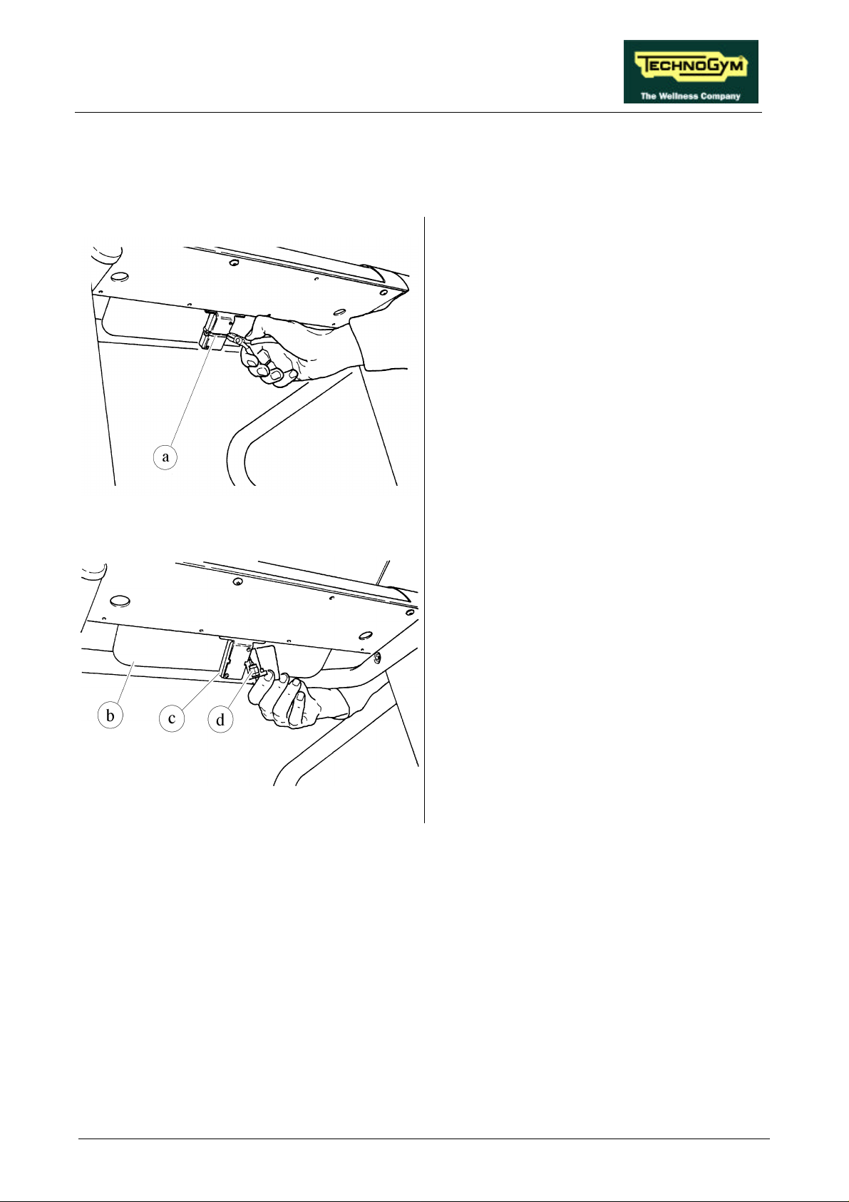
RUN XT: Service & Maintenance Manual - rev. 2.0
7.5. DISASSEMBLING THE CARDIO RECEIVER
Version A: receiver positioned under the display.
1. Place the machine in its maximum elevation
position.
2. Turn off the machine and unplug the mains
lead from the wall outlet.
3. Cut strap a.
Figure 7.5-1
Figure 7.5-2
4. Lift the lexan instruction panel b, and open
the box c which houses the RECEIVER.
5. Disconnect connector d of cable BK-7 from
the RECEIVER.
6. Remove the RECEIVER.
To reassemble the RECEIVER, carry out the
above steps in reverse order, positioning it
between the 2 foam pads and using a new strap
to secure the box.
Page 7.5
Page 74
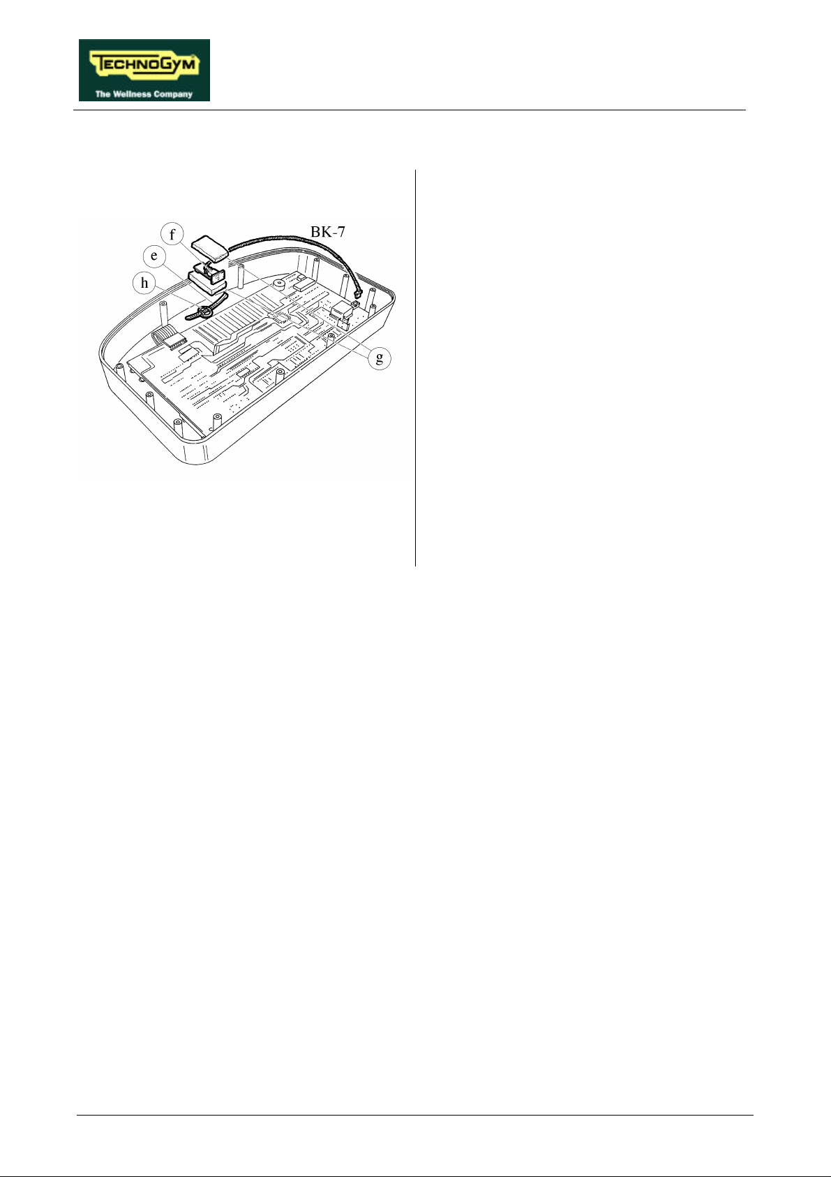
RUN XT: Service & Maintenance Manual - rev. 2.0
Version B: receiver positioned inside the display, secured by a strap.
Carry out the procedure described in paragraph
7.1. “Disassembling the display”.
With the display on a work bench:
1. Cut the fixing strap e.
2. Disconnect the connector f of RECEIVER
cable BK-7.
To assemble the new RECEIVER, with the
display on a work bench:
1. Connect the connector f of RECEIVER cable
BK-7.
2. Position the RECEIVER between the foam
Figure 7.5-3
pads g as shown in the figure at left.
3. Passing the strap through clamp h, fix and
secure with the strap.
Page 7.6
Page 75
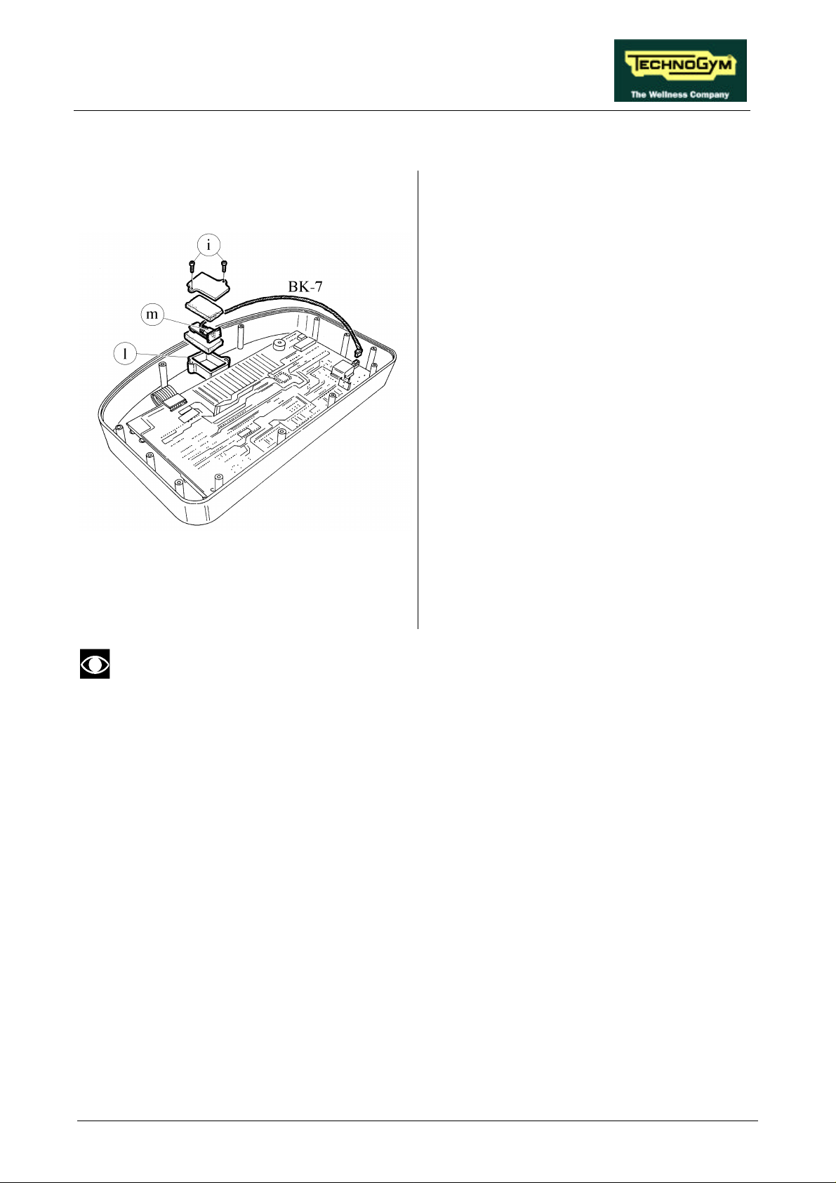
RUN XT: Service & Maintenance Manual - rev. 2.0
Version C: receiver housed in a box inside the display.
Carry out the procedure described in paragraph
7.1. “Disassembling the display”.
With the display on a work bench:
1. Unscrew the screws i on RECEIVER housing
2. Disconnect the connector m of RECEIVER
To assemble the new RECEIVER, with the
display on a work bench:
box l using a small Phillips screwdriver.
cable BK-7.
3. Connect connector m of RECEIVER cable
BK-7.
Figure 7.5-4
4. Position the RECEIVER in the box as shown
in the figure at left.
5. Lock down the screws i of the RECEIVER
housing box.
WARNING: route the cables as described in paragraph 11.1. “Technical notes on cardio
receivers”.
Page 7.7
Page 76
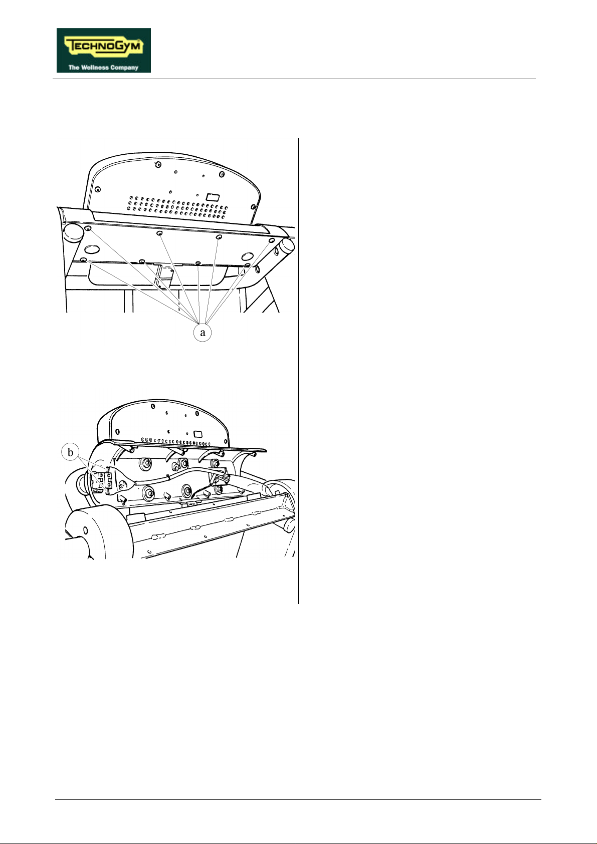
RUN XT: Service & Maintenance Manual - rev. 2.0
7.6. DISASSEMBLING THE EMERGENCY BUTTON
1. Turn off the machine and unplug the mains
lead from the wall outlet.
2. Unscrew the 8 self-tapping screws a which
fix the DISPLAY, using a large Phillips
screwdriver.
Figure 7.6-1
Figure 7.6-2
3. Open the display panel support.
4. Disconnect the two EMERGENCY
BUTTON wires b, using a large Phillips
screwdriver.
Continued on the following page→
Page 7.8
Page 77
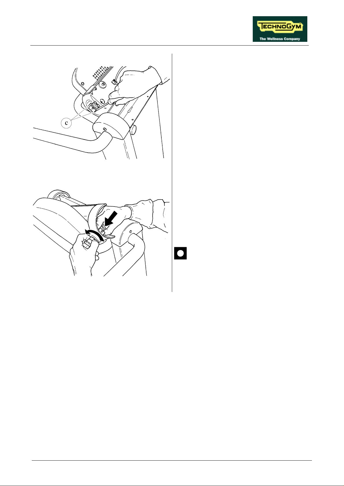
RUN XT: Service & Maintenance Manual - rev. 2.0
Figure 7.6-3
5. Back off the 2 screws c which fix the
EMERGENCY BUTTON to the panel using
a large Phillips screwdriver.
6. Firmly gripping the inner part, push and
rotate the EMERGENCY BUTTON to
detach it.
Figure 7.6-4
To reassemble the EMERGENCY BUTTON,
carry out the above steps in reverse order.
For the 4-terminal version of the
emergency button, remember to connect
the wires in position 1-2 (NC button).
Page 7.9
Page 78
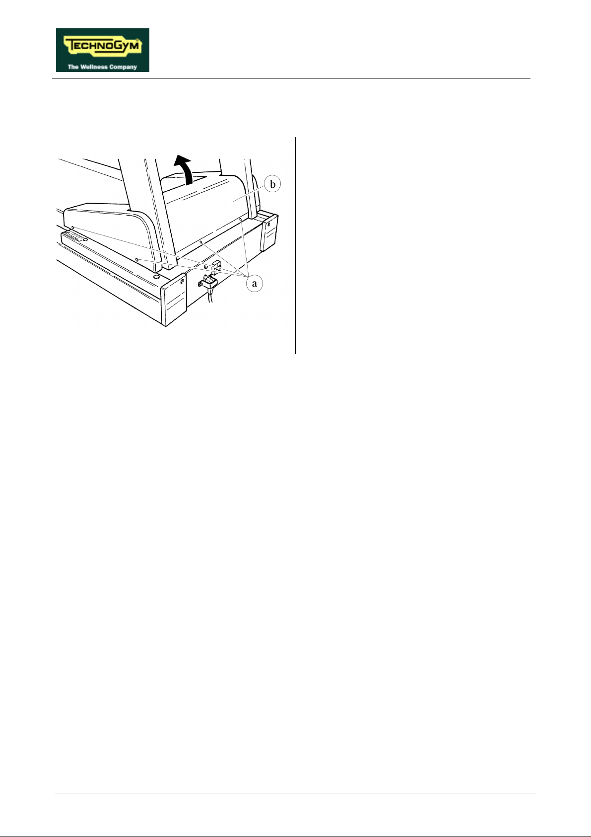
RUN XT: Service & Maintenance Manual - rev. 2.0
7.7. DISASSEMBLING THE MOTOR GUARD
1. Turn off the machine and unplug the mains
lead from the wall outlet.
2. Unscrew the 6 screws a using a large Phillips
screwdriver.
3. Remove the MOTOR GUARD b.
To reassemble the MOTOR GUARD, carry out
the above steps in reverse order.
Figure 7.7-1
Page 7.10
Page 79
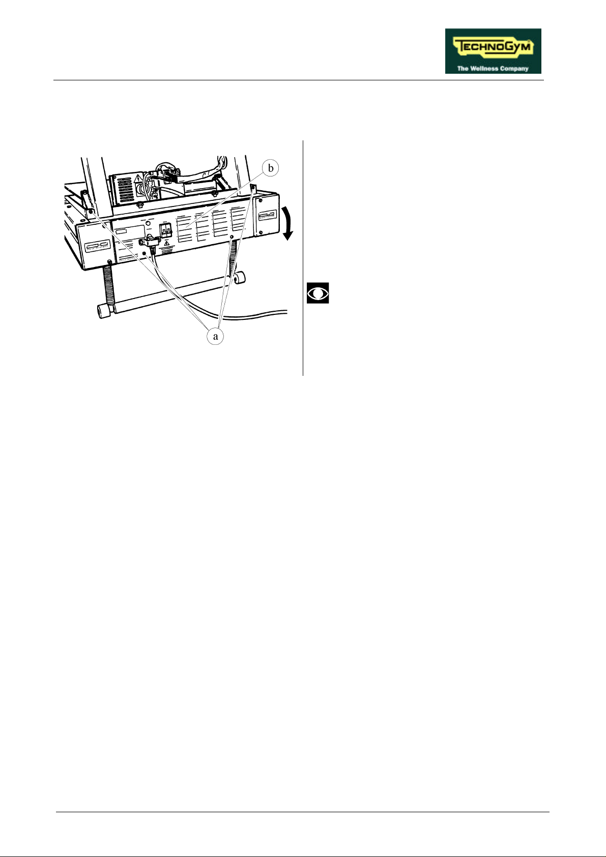
RUN XT: Service & Maintenance Manual - rev. 2.0
7.8. DISASSEMBLING THE FRONT PLATE
1. Carry out the procedure described in
paragraph 7.7. “Disassembling the motor
guard”.
2. Unscrew the 4 self-tapping screws a using a
large Phillips screwdriver.
3. Rotate the FRONT PLATE b downward.
The plate remains connected to the
frame by two steel cables.
To reassemble the FRONT PLATE, carry out the
Figure 7.8-1
above steps in reverse order.
Page 7.11
Page 80
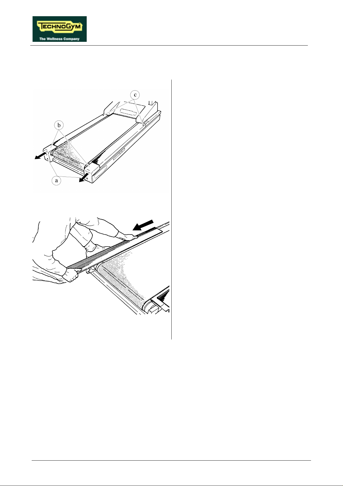
RUN XT: Service & Maintenance Manual - rev. 2.0
7.9. DISASSEMBLING THE RUNNING TRACK
1. Turn off the machine and unplug the mains
lead from the wall outlet.
2. Unscrew the 2 screws a using a 6-mm Allen
T wrench.
3. Remove the rear caps b on the right and left
hand sides.
4. Unscrew the 2 screws c fixing the footrests
using a 5-mm Allen T wrench.
Figure 7.9-1
Figure 7.9-2
5. Remove the footrests by pulling them toward
the back of the machine.
Continued on the following page→
Page 7.12
Page 81
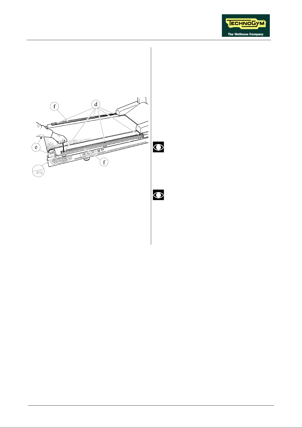
RUN XT: Service & Maintenance Manual - rev. 2.0
6. Depending on the type of shock absorbers:
• Unscrew the 6 screws d using a 5-mm
Allen T wrench.
• Unscrew the 2 rear screws d using a 5-
mm Allen T wrench, and the 4 front
screws using a 5-mm Allen T wrench
while holding the nut in place with a 13mm wrench.
7. Remove the 2 footrest guides f.
8. Pull out the RUNNING TRACK from the
side.
The front and rear profiles of the
RUNNING TRACK are different, and
therefore it is necessary to mark the
correct positions in order to avoid errors
during the reassembly phase.
Figure 7.9-3
Before reassembling the caps, check that
the fixing bolts are in the position
indicated in the figure.
To reassemble the RUNNING TRACK, carry out
the above steps in reverse order.
Page 7.13
Page 82
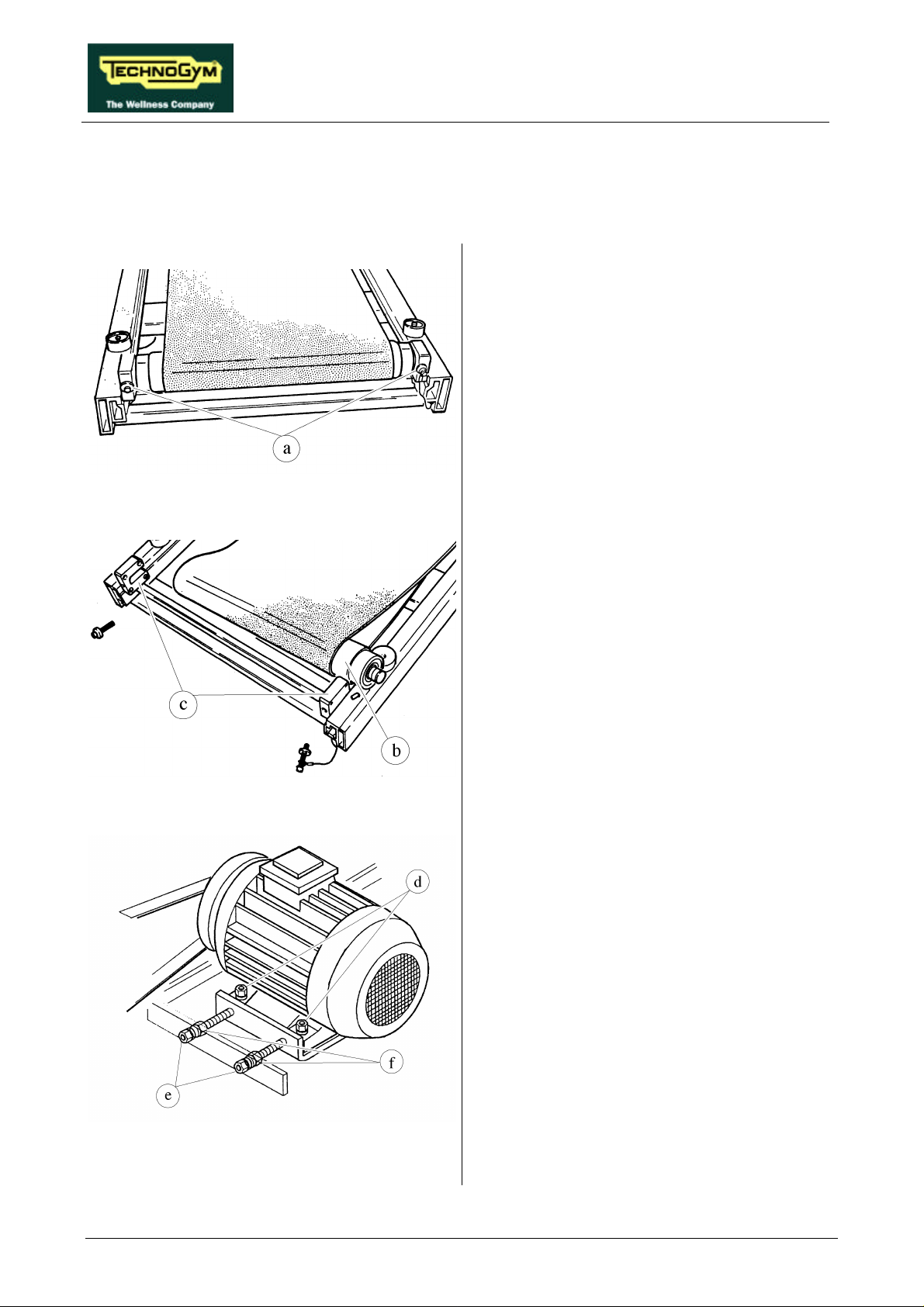
RUN XT: Service & Maintenance Manual - rev. 2.0
7.10. DISASSEMBLING THE DRIVEN ROLLER, THE DRIVING
ROLLER, THE TREAD BELT AND THE MOTOR BELT
1. Place the machine in the maximum elevation
position.
2. Carry out the procedure described in
paragraphs 7.7. “Disassembling the motor
guard” and 7.9. “Disassembling the running
track”.
3. Remove the dust guard.
4. Unscrew the 2 screws a using a 6-mm Allen
Figure 7.10-1
T wrench.
Figure 7.10-2
5. Pull out the DRIVEN ROLLER b from its
supports c.
6. Remove the DRIVEN ROLLER.
7. Back off the 4 nuts d (2 are concealed by the
motor in the figure at left) which fix the belt
motor to the machine frame using a 13-mm
wrench, and holding the screw underneath in
place with a 6-mm Allen T wrench.
8. Back off the 2 outer nuts e and the 2 inner
nuts f using a 13-mm wrench.
Page 7.14
Figure 7.10-3
Continued on the following page→
Page 83
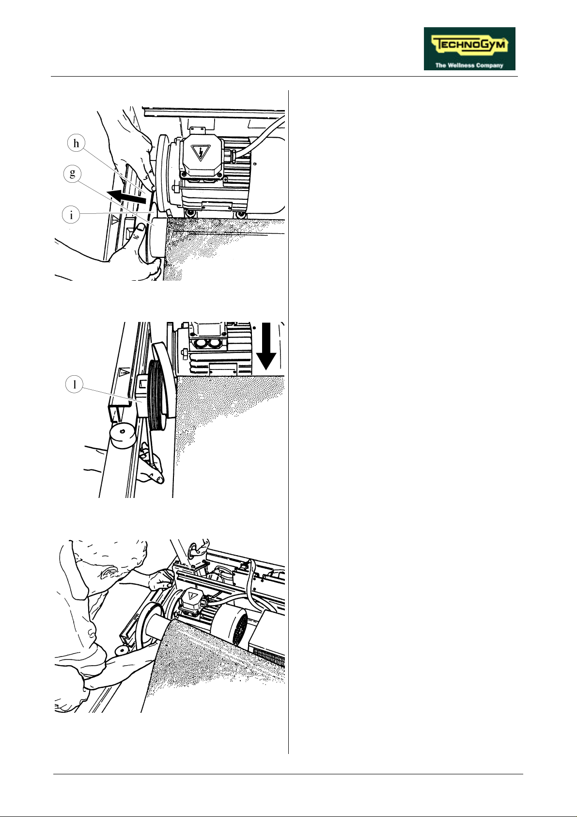
RUN XT: Service & Maintenance Manual - rev. 2.0
Figure 7.10-4
9. Move the belt motor toward the DRIVING
ROLLER g and pull outward to remove belt
h from the motor pulley i.
Figure 7.10-5
10. Unscrew the 2 fixing screws of the DRIVING
ROLLER l using a 6-mm Allen T wrench.
11. Disengage the DRIVING ROLLER from its
supports.
12. Remove the MOTOR BELT by pulling it out
from the DRIVING ROLLER.
13. Remove the DRIVING ROLLER.
14. Remove the TREAD BELT.
Figure 7.10-6
Continued on the following page →
Page 7.15
Page 84
RUN XT: Service & Maintenance Manual - rev. 2.0
To reassemble the DRIVEN ROLLER, the
DRIVING ROLLER, the TREAD BELT and the
MOTOR BELT, carry out the above steps in
reverse order.
To ensure correct reassembly, insert the
DRIVING ROLLER in the MOTOR
BELT before assembling it on the
supports.
After completing this procedure, adjust
the tension and centering of the TREAD
BELT as described in paragraphs 8.1.
8.2. 8.3. and adjust the tension and
alignment of the MOTOR BELT as
described in paragraph 8.4.
Page 7.16
Page 85
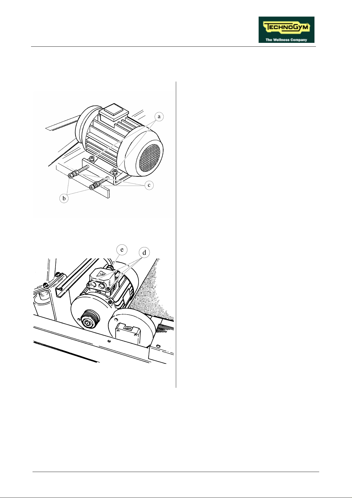
RUN XT: Service & Maintenance Manual - rev. 2.0
7.11. DISASSEMBLING THE BELT MOTOR
1. Carry out the procedure described in
paragraph 7.7. “Disassembling the motor ”.
2. Remove the dust guard.
3. Unscrew the 4 nuts a (2 are concealed by the
motor in the figure at left) which fix the belt
motor to the machine frame using a 13-mm
wrench and holding the screw underneath in
place with a 6-mm Allen T wrench.
4. Back off the 2 outer nuts b and the 2 inner
nuts c using a 13-mm wrench.
5. Move the BELT MOTOR toward the driving
roller.
6. Disengage the motor belt.
Figure 7.11-1
Figure 7.11-2
7. Unscrew the 4 screws d of the BELT
MOTOR cover using a large Phillips
screwdriver.
8. Back off the cable clamp e.
9. Open the cover.
Continued on the following page →
Page 7.17
Page 86
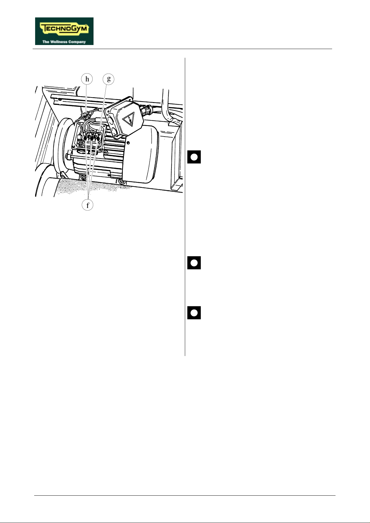
RUN XT: Service & Maintenance Manual - rev. 2.0
10. Disconnect the 3 phase conductors f using a
7-mm wrench, the ground conductor g using
a large Phillips screwdriver, and the motor
thermal cutout h using a small flat-blade
screwdriver.
Make sure that no nuts or washers fall
inside the BELT MOTOR.
11. Remove the BELT MOTOR.
Figure 7.11-3
To reassemble the BELT MOTOR, carry out the
above steps in reverse order.
When locking down the cover screws,
make sure that the conductors inside the
box are correctly positioned to avoid
pinching them with the cover.
After completing the procedure, adjust
the tension and alignment of the
MOTOR BELT as described in
paragraph 8.4. .
Page 7.18
Page 87
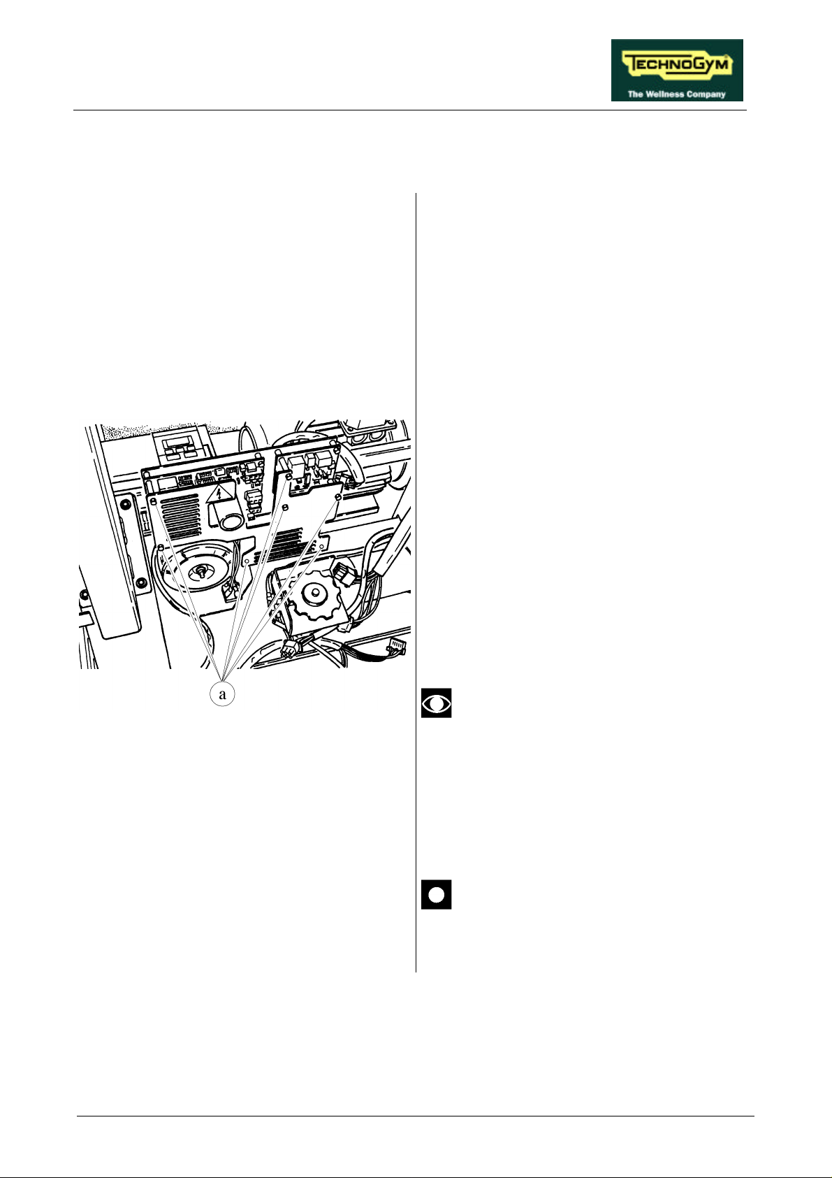
RUN XT: Service & Maintenance Manual - rev. 2.0
7.12. DISASSEMBLING THE ELECTRONIC CIRCUIT BOARDS
1. Carry out the procedures described in
paragraphs 7.7. “Disassembling the motor
guard” and 7.8. “Disassembling the front
plate”.
2. Cut any straps fixing the cables to the grille
protecting the ELECTRONIC CIRCUIT
BOARDS.
3. Unscrew the 7 plastic hexagonal-head screws
a which secure the protective grille using a 7mm wrench.
4. Remove the protective grille.
Figure 7.12-1
To disassemble an ELECTRONIC CIRCUIT
BOARD:
5. Disconnect all the connectors.
6. Unscrew the screws fixing it to the plate
support using a 7-mm socket wrench.
7. Manually unscrew the fixing studs of the
protective grille.
8. Remove the ELECTRONIC CIRCUIT
BOARD.
To remove the up-down board it is
sufficient to disconnect the red and
black cables; the yellow cables pertain to
the transformer.
To reassemble the ELECTRONIC CIRCUIT
BOARDS, carry out the above steps in reverse
order.
After reassembling the inverter interface
board, calibrate the speed as instructed
in paragraph 8.7. .
Page 7.19
Page 88
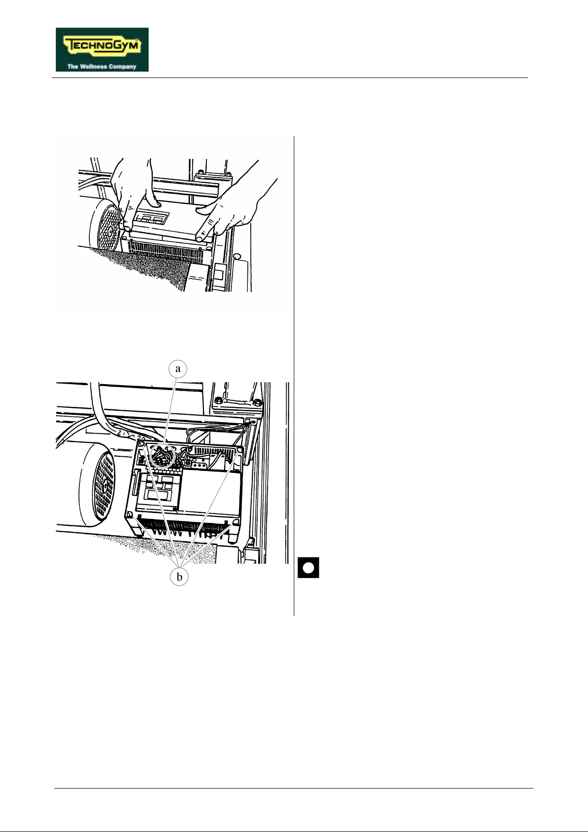
RUN XT: Service & Maintenance Manual - rev. 2.0
using a
7.13. DISASSEMBLING THE INVERTER
1. Carry out the procedure described in
paragraph 7.7. “Disassembling the motor
guard”.
2. Remove the INVERTER cover, using a small
Phillips screwdriver to unscrew the fixing
screw, if present.
Figure 7.13-1
Figure 7.13-2
3. Disconnect the electrical cables a
small flat-head screwdriver for the logic
signals (upper terminal block) and a medium
flat-blade screwdriver for the power signals
(lower terminal block).
4. Disconnect the yellow-green ground
conductor of the inverter using a medium
Phillips screwdriver.
5. Unscrew the 4 fixing screws b using a 4-mm
Allen T wrench.
6. Remove the INVERTER.
To reassemble the INVERTER, carry out the
above steps in reverse order.
After completing this procedure,
calibrate the speed as instructed in
paragraph 8.7. .
Page 7.20
Page 89
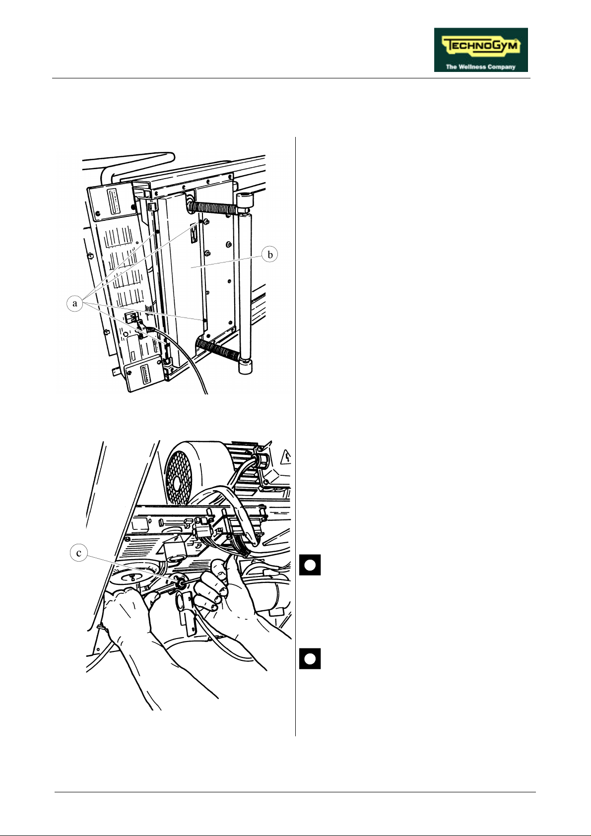
RUN XT: Service & Maintenance Manual - rev. 2.0
7.14. DISASSEMBLING THE UP-DOWN MOTOR BELT
1. Place the machine in its maximum elevation
position.
2. Carry out the procedures described in
paragraphs 7.7. “Disassembling the motor
guard” and 7.8. “Disassembling the front
plate”.
3. Overturn the machine on the right hand side.
4. Using a large Phillips screwdriver, unscrew
the 4 self-tapping screws a.
5. Remove the belt guard b.
Figure 7.14-1
6. Holding the pivot in place with a 5-mm Allen
T wrench, back off the self-tapping nut of belt
tensioner c using a 17-mm wrench.
7. Rotate the belt tensioner to slacken the
BELT.
8. Remove the BELT.
When removing the BELT, be careful
not to rotate the lead screw nuts.
To reassemble the BELT, carry out the above
steps in reverse order.
After completing this procedure, adjust
the tension of the UP-DOWN MOTOR
BELT as instructed in paragraph 8.5. .
Figure 7.14-2
Page 7.21
Page 90
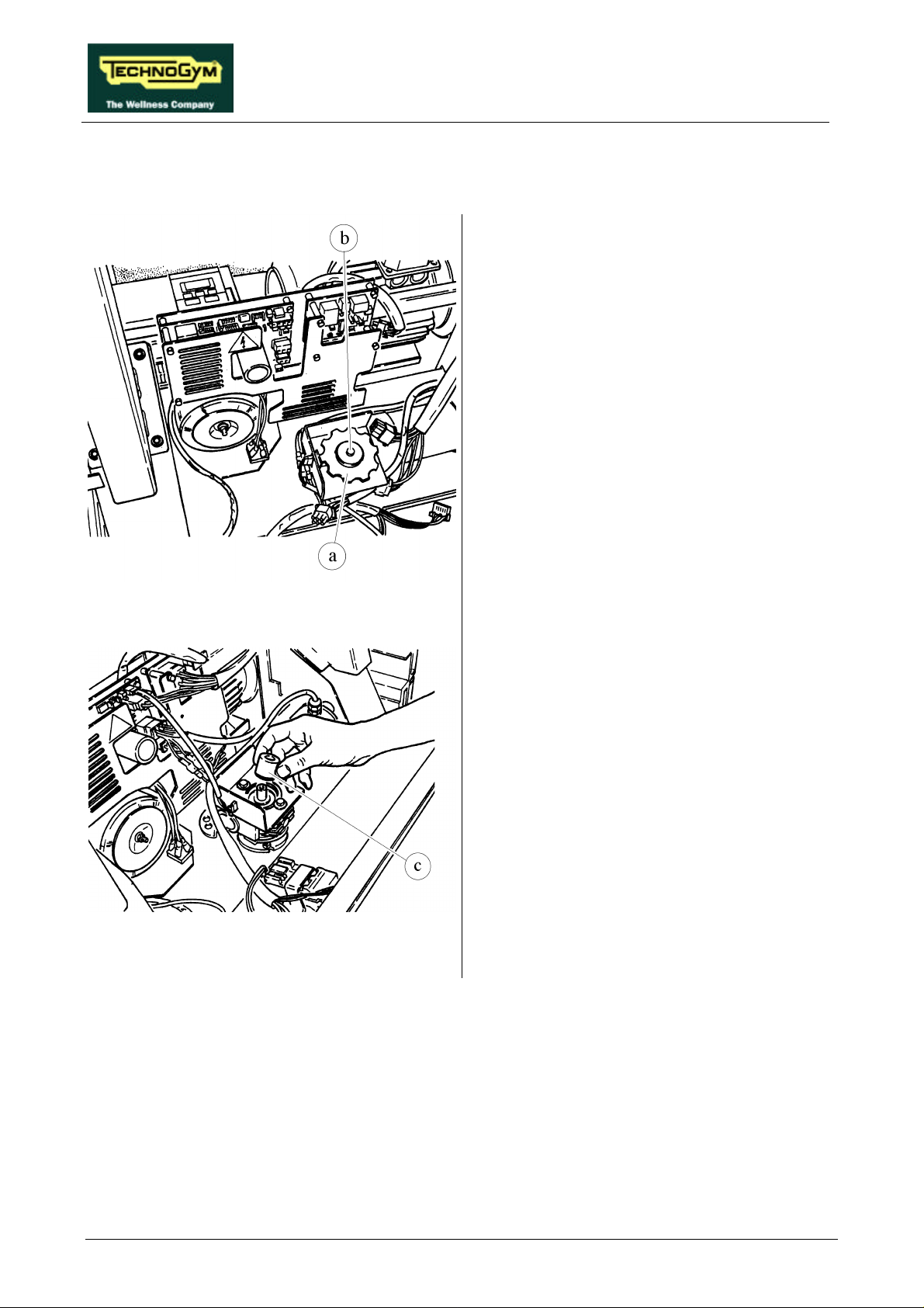
RUN XT: Service & Maintenance Manual - rev. 2.0
7.15. DISASSEMBLING THE UP-DOWN MOTOR
1. Carry out the procedure described in
paragraph 7.14. “Disassembling the up-down
motor belt” up to the slackening of the belt
(step 7).
2. Disconnect the motor power supply cable and
the photocell cable.
3. If present, use a 10-mm wrench to remove
the 2 fixing screws from the cover of the
protective housing of encoder wheel a
4. Open the cover.
Figure 7.15-1
Figure 7.15-2
5. Use a 10-mm wrench to remove screw b.
6. Disassemble encoder wheel a.
7. Remove the spacer c.
Continued on the following page →
Page 7.22
Page 91
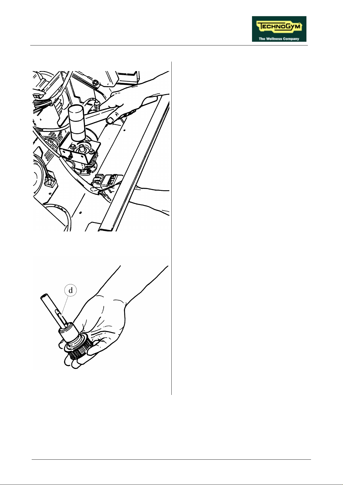
RUN XT: Service & Maintenance Manual - rev. 2.0
8. Strike the motor shaft with a rubber hammer,
and, using a pointed tool if necessary, remove
the shaft from the lower side of the machine.
Figure 7.15-3
Figure 7.15-4
9. Recover the tab d.
Continued on the following page→
Page 7.23
Page 92
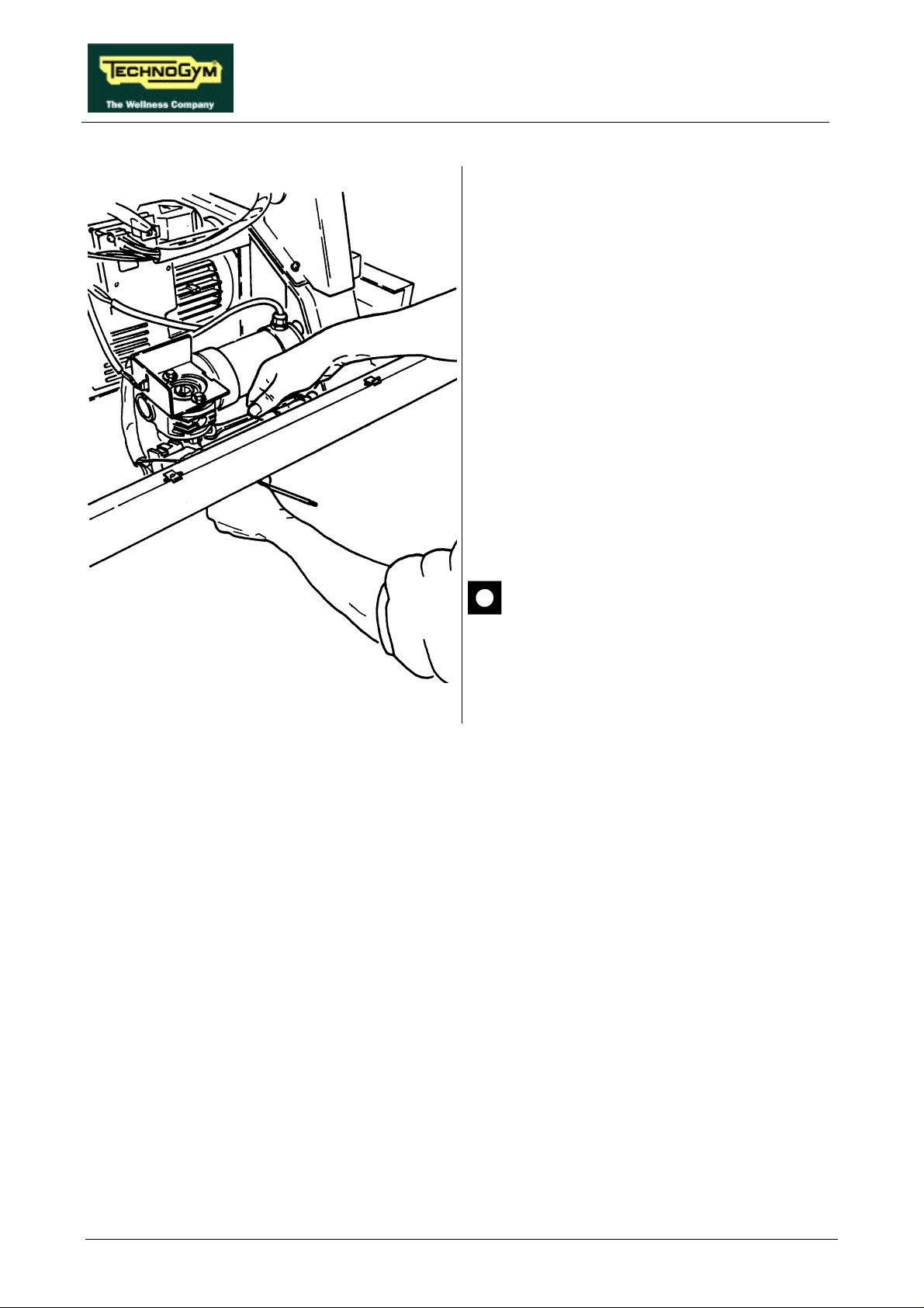
RUN XT: Service & Maintenance Manual - rev. 2.0
DOWN MOTOR using a 4-mm Allen T
10. Disassemble protective housing of the
encoder wheel, using, depending on the type
of motor:
• “BONFIGLIOLI” motor: 10-mm wrench;
• “SITI” motor: 8-mm wrench.
11. Unscrew the 4 fixing screws of the UP-
wrench and holding the nut in place with a
10-mm wrench.
12. Remove the UP-DOWN MOTOR.
Figure 7.15-5
To reassemble the UP-DOWN MOTOR, carry
out the above steps in reverse order.
After completing the procedure, adjust
the tension of the up-down motor belt as
instructed in paragraph 8.5. .
Page 7.24
Page 93
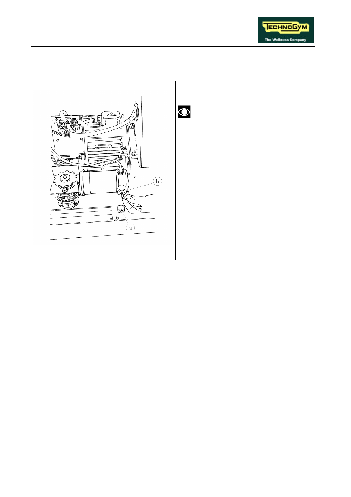
RUN XT: Service & Maintenance Manual - rev. 2.0
7.16. DISASSEMBLING THE UP-DOWN MOTOR BRUSHES
It is not possible to carry out this
procedure on all types of motors.
1. Carry out the procedures described in
paragraphs 7.7. “Disassembling the motor
guard” and 7.8. “Disassembling the front
plate”.
2. Manually, or using a small flat-head
screwdriver, unscrew the protective caps a of
the brushes.
3. Remove the BRUSHES b.
Figure 7.16-1
To reassemble the BRUSHES, carry out the
above steps in reverse order.
Page 7.25
Page 94
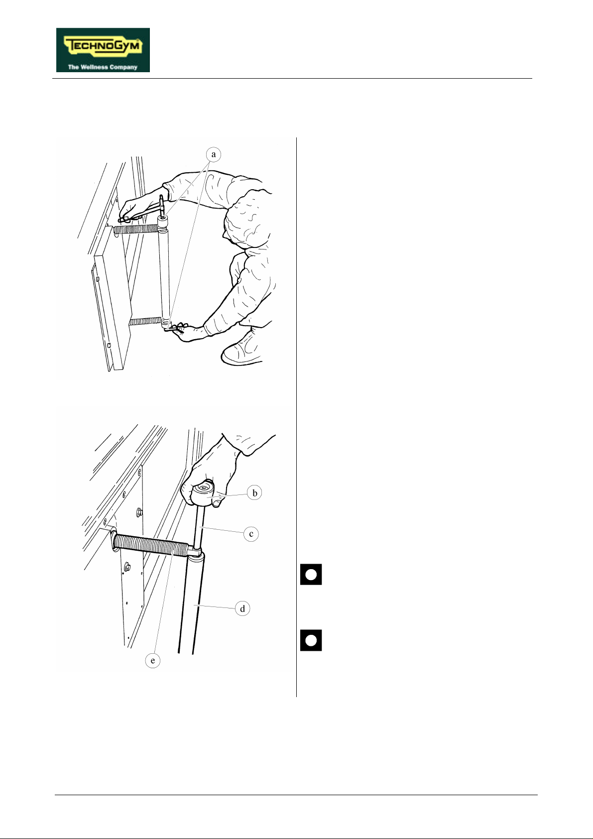
RUN XT: Service & Maintenance Manual - rev. 2.0
Remove, unscrewing them by hand, the 2
7.17. DISASSEMBLING THE ELEVATION BARS
1. Place the machine in its maximum elevation
position.
2. Carry out the operations described in
paragraphs 7.7. “Disassembling the motor
guard” and 7.8. “Disassembling the front
plate”.
3. Overturn the machine on its right hand side.
4. Unscrew the two fixing screws of wheels a
using two 6-mm T wrenches.
Figure 7.17-1
Figure 7.17-2
5. Remove wheel b.
6. Remove the wheel shaft c.
7. Remove spacer d.
8.
ELEVATION BARS e.
To reassemble the ELEVATION BARS, carry
out the above steps in reverse order.
During the reassembly phase, lubricate
the elevation bars with MOLYKOTE
GN PLUS grease.
After completing the procedure, adjust
the alignment of the ELEVATION
BARS as instructed in paragraph 8.6. .
Page 7.26
Page 95
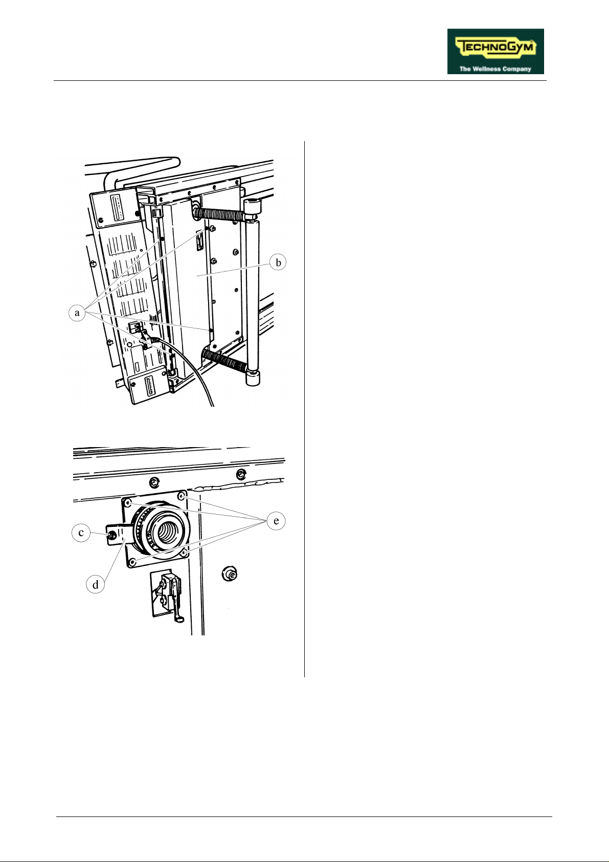
RUN XT: Service & Maintenance Manual - rev. 2.0
7.18. DISASSEMBLING THE LEAD SCREW NUTS
1. Place the machine in its maximum elevation
position.
2. Carry out the procedures described in
paragraphs 7.7. “Disassembling the motor
guard” and 7.8. “Disassembling the front
plate”.
3. Overturn the machine on its right hand side.
4. Using a large Phillips screwdriver unscrew
the 4 self-tapping screws a.
5. Remove the belt guard b.
Figure 7.18-1
Figure 7.18-2
6. Carry out the procedure described in
paragraph 7.17. “Disassembling the elevation
bars”.
7. Back off the bearing clamp screw c using a 4-
mm Allen T wrench.
8. Rotate the clamp d.
9. Unscrew the 4 screws e using a 4-mm Allen
T wrench.
Continued on the following page →
Page 7.27
Page 96
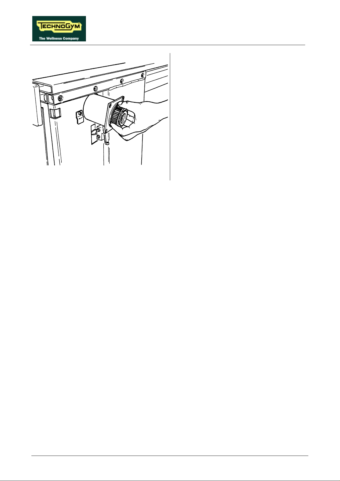
Figure 7.18-3
RUN XT: Service & Maintenance Manual - rev. 2.0
10. Remove the LEAD SCREW NUT GROUP.
To reassemble the LEAD SCREW NUT
GROUP, carry out the above steps in reverse
order.
Page 7.28
Page 97
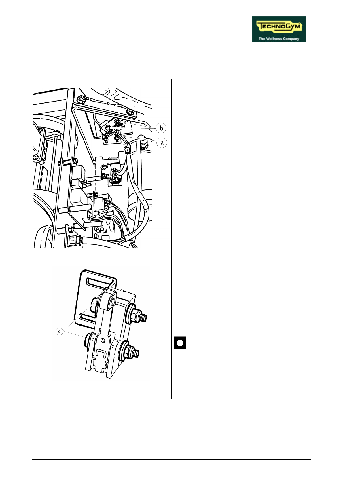
RUN XT: Service & Maintenance Manual - rev. 2.0
7.19. DISASSEMBLING THE LIMIT SWITCHES
1. Carry out the procedures described in
paragraphs 7.7. “Disassembling the motor
guard” and 7.8. “Disassembling the front
plate”.
To remove the LIMIT SWITCHES:
2. Disconnect the cables a.
3. Unscrew the 2 fixing screws b of the LIMIT
SWITCH support bracket using a 3-mm
Allen T wrench.
4. Remove the LIMIT SWITCH group and the
supporting bracket.
Figure 7.19-1
Figure 7.19-2
5. To remove the LIMIT SWITCHES from the
supporting bracket, unscrew the 2 screws c
using a 3-mm Allen T wrench while holding
the nut underneath in place with an 8-mm
wrench.
To reassemble the LIMIT SWITCHES, carry out
the above steps in reverse order.
When reconnecting the cables,
remember that the UPPER LIMIT
SWITCH is connected between
terminals 1 and 3, and the LOWER
LIMIT SWITCH is between terminals 1
and 2.
Page 7.29
Page 98
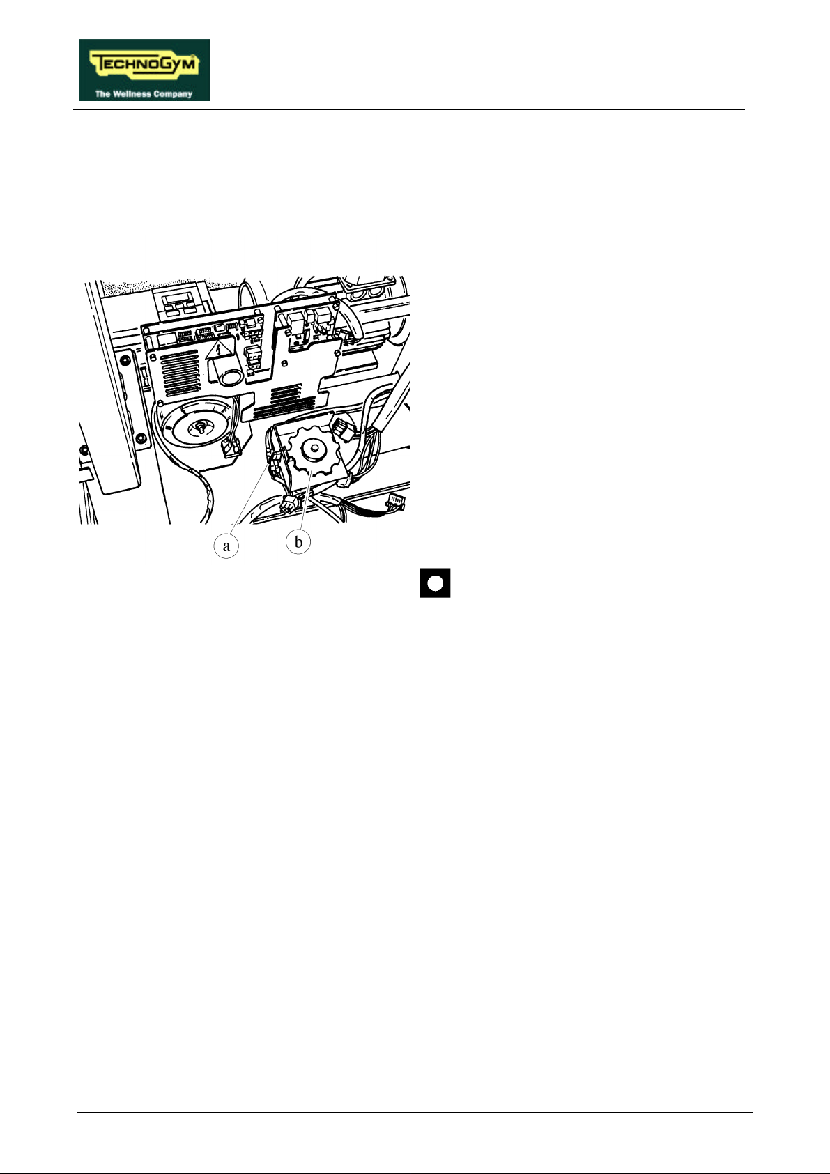
RUN XT: Service & Maintenance Manual - rev. 2.0
7.20. DISASSEMBLING THE PHOTOCELL
1. Carry out the procedures described in
paragraphs 7.7. “Disassembling the motor
guard” and 7.8. “Disassembling the front
plate”.
2. Disconnect connector a on the PHOTOCELL
board.
3. Using a 10-mm wrench, unscrew the 2 screws
fixing the cover of the protective housing of
encoder wheel b if present.
4. Open the cover.
Figure 7.20-1
5. Unscrew the 2 screws fixing the
PHOTOCELL board to the support using a
small Phillips screwdriver.
6. Remove the PHOTOCELL board.
There are 2 versions of photocell,
distinguished by the name of the printed
circuit board on which they are
mounted, which require a specific
version of the SW for the up-down
board microcontroller:
• board GF970711 operates with SW
RX42V2;
• board GF920415 operates with SW
RUNXT42.
To reassemble the PHOTOCELL, carry out the
above steps in reverse order.
Page 7.30
Page 99
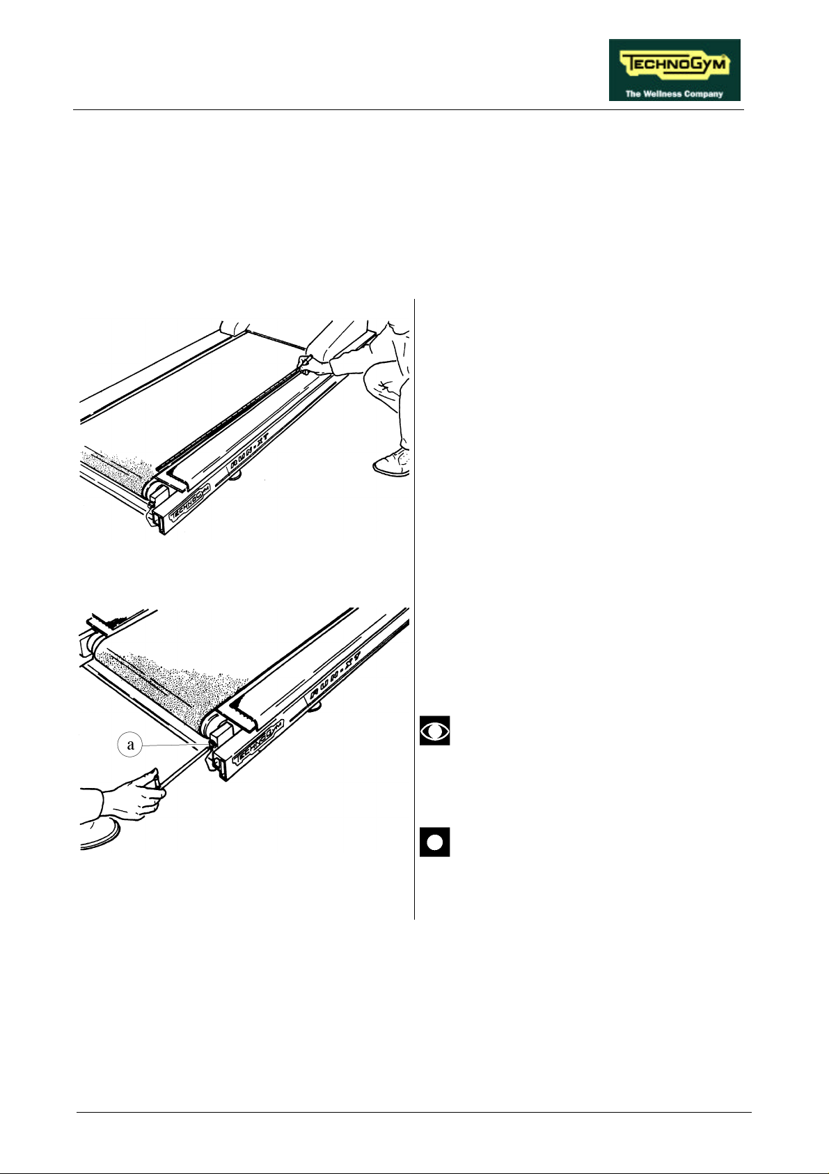
RUN XT: Service & Maintenance Manual - rev. 2.0
8. ADJUSTMENTS
8.1. TENSIONING A NEW TREAD BELT
1. After assembling the new tread belt, tighten
the tread belt until it is just slightly taut.
2. Place a tape measure along the right hand
edge of the tread belt, and use a pen make
two reference marks on the tread belt at a
distance of exactly 1 meter from each other.
Figure 8.1-1
Figure 8.1-2
3. Lock down the right hand tread belt tensioner
screw a until the distance between the
reference marks increases by 7 mm.
4. Lock down the left hand tread belt tensioner
screw until the driven roller is aligned with
the crosspiece.
After completing this procedure, any
further adjustments should be
performed using only the left-hand
tensioning screw.
After completing this procedure, check
the centering of the tread belt as
instructed in paragraph 8.3.
Page 8.1
Page 100
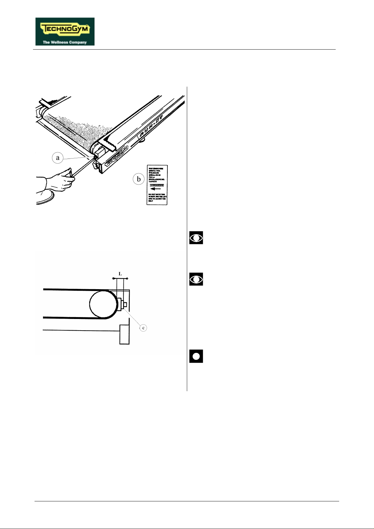
RUN XT: Service & Maintenance Manual - rev. 2.0
8.2. TENSIONING A USED TREAD BELT
1. After completing reassembly of the used tread
belt, lock down the rear right hand screw a
until measurement L in Figure 8.2-2
corresponds to the value shown on the red
decal b on the inside of the rear right hand
cap.
2. Lock down the left hand tread belt tensioning
screw until the drive roller is aligned with the
crosspiece.
Figure 8.2-1
Figure 8.2-2
Use a gauge to measure the distance
between the surface of the driven roller
and the outer edge of spacer c.
This procedure is normally carried out
after replacing the driving or driven
rollers, or in those cases where it is
necessary to reassemble the used tread
belt: it is not possible to carry out the
procedure as described in 8.1. because
the tread belt is not elastic.
After completing this procedure, check
the centering of the tread belt as
described in paragraph8.3. .
Page 8.2
 Loading...