

Technogym Run Excite 500, Run Excite 700, Run Excite 700E, Run Excite 900, Run Excite 900E Service Maintenance Manual

S
ERVICE
&
MAINTENANCE MANUAL
REV. 1.5


The information contained in this manual is intended for QUALIFIED TECHNICIANS who have
completed a specific TECHNOGYM training course and are authorized to perform machine start-
up and adjustment procedures as well as extraordinary maintenance or repairs which require a
thorough knowledge of the machine, its operation, its safety devices and working procedures.
CAREFULLY READ THE INFORMATION CONTAINED IN
THIS MANUAL BEFORE PERFORMING ANY MAINTENANCE
PROCEDURES ON THE MACHINE
DANGEROUS VOLTAGES
PRESENT
NOTE
The information contained in this document is subject to change without notice.
Technogym does not guarantee this documentation in any way. Technogym shall not be held
responsible for any errors contained in this manual and declines all liability for accidents or
damages resulting from the supply, characteristics or use of this manual.
This document contains proprietary information that is protected by copyright. All rights reserved.
No part of this document may be photocopied,
without the prior written consent of Technogym.
The Technogym™ trademark is property of Technogym S.p.A.
The Run Excite™ trademark is property of Technogym S.p.A.
reproduced or translated into another language


RUN EXCITE: Service & Maintenance Manual - rev. 1.5
Contents
1. GENERAL NOTICES...........................................................................................................................................1.1
1.1. I
1.2. R
1.3. G
2. TECHNICAL CHARACTERISTICS..................................................................................................................2.1
2.1. A
2.2. M
2.3. E
2.4. C
2.5. A
2.6. P
2.7. W
2.8. W
NTRODUCTION
ECOMMENDATIONS
ENERAL RULES FOR REPAIR PROCEDURES
VAILABLE VERSIONS
ECHANICAL CHARACTERISTICS
LECTRICAL CHARACTERISTICS
ONFORMITY REGULATIONS
MBIENT SPECIFICATIONS
RODUCT CODES
IRING DIAGRAM
2.7.1. 900 model ....................................................................................................................................... 2.5
2.7.2. 700 model ....................................................................................................................................... 2.9
2.7.3. 500 model ..................................................................................................................................... 2.13
IRING
........................................................................................................................................................ 2.16
.............................................................................................................................................. 1.1
..................................................................................................................................... 1.1
.................................................................................................... 1.2
................................................................................................................................... 2.1
................................................................................................................... 2.1
..................................................................................................................... 2.2
.......................................................................................................................... 2.2
............................................................................................................................. 2.3
............................................................................................................................................ 2.3
.......................................................................................................................................... 2.5
2.7.1.1. EU 220 VAC lower assembly.....................................................................................................................................2.5
2.7.1.2. UL 220 VAC lower assembly.....................................................................................................................................2.6
2.7.1.3. UL 110 VAC lower assembly.....................................................................................................................................2.6
2.7.1.4. Upper assembly: LED version ....................................................................................................................................2.7
2.7.1.5. Upper assembly: Wellness TV version.......................................................................................................................2.8
2.7.2.1. EU 220 VAC lower assembly.....................................................................................................................................2.9
2.7.2.2. UL 220 VAC lower assembly...................................................................................................................................2.10
2.7.2.3. UL 110 VAC Lower assembly..................................................................................................................................2.10
2.7.2.4. Upper assembly, LED version ..................................................................................................................................2.11
2.7.2.5. Upper assembly: Wellness TV version.....................................................................................................................2.12
2.7.3.1. EU 220 VAC lower assembly...................................................................................................................................2.13
2.7.3.2. UL 220 VAC lower assembly...................................................................................................................................2.14
2.7.3.3. UL 110 VAC Lower assembly..................................................................................................................................2.14
2.7.3.4. Upper assembly, LED version ..................................................................................................................................2.15
3. PRINCIPLES OF OPERATION..........................................................................................................................3.1
3.1. B
3.2. T
LOCK DIAGRAM
3.1.1. Display boards................................................................................................................................3.1
3.1.1.1. 500 LED model ...........................................................................................................................................................3.1
3.1.1.2. 700 / 900 LED models ................................................................................................................................................3.2
3.1.1.3. 700E / 900E models (Wellness TV )...........................................................................................................................3.4
3.1.2. CSafe Board....................................................................................................................................3.6
3.1.3. TGS/Smart Card Board..................................................................................................................3.6
3.1.4. Hand sensor Board.........................................................................................................................3.6
3.1.5. Cardio receiver............................................................................................................................... 3.6
3.1.6. Joystick ........................................................................................................................................... 3.7
3.1.7. Emergency Switch...........................................................................................................................3.7
3.1.8. Relay............................................................................................................................................... 3.7
3.1.9. Inverter ........................................................................................................................................... 3.7
3.1.10. Belt motor.......................................................................................................................................3.8
3.1.11. Power supply Board ....................................................................................................................... 3.8
3.1.12. Download Board ............................................................................................................................3.8
3.1.13. Elevation + Cut-out Board.............................................................................................................3.9
3.1.14. Elevation motor ............................................................................................................................3.11
3.1.15. Autotransformer............................................................................................................................3.11
3.1.16. Limit switch...................................................................................................................................3.11
READ BELT MOTOR DRIVE
3.2.1. Mechanics.....................................................................................................................................3.12
3.2.2. Controls........................................................................................................................................3.12
........................................................................................................................................... 3.1
.......................................................................................................................... 3.12
Page i

RUN EXCITE: Service & Maintenance Manual - rev. 1.5
3.2.3. The signals involved ..................................................................................................................... 3.13
3.3. E
3.4. E
LEVATION MOTOR DRIVE
3.3.1. Mechanics.....................................................................................................................................3.14
3.3.2. Control..........................................................................................................................................3.14
3.3.3. The reset procedure...................................................................................................................... 3.15
3.3.4. The signals involved ..................................................................................................................... 3.15
MERGENCY STOP MANAGEMENT
3.4.1. Control..........................................................................................................................................3.17
3.4.2. The signals involved ..................................................................................................................... 3.18
........................................................................................................................... 3.14
................................................................................................................ 3.17
4. ACCESSORIES ..................................................................................................................................................... 4.1
4.1. C
4.2. PC
4.3. P
4.4. C
4.5. M
4.6. W
5. INSTALLATION INSTRUCTIONS....................................................................................................................5.1
5.1. S
5.2. S
5.3. I
5.4. F
6. TROUBLESHOOTING ........................................................................................................................................ 6.1
6.1. T
6.2. T
6.3. T
6.4. T
6.5. T
6.6. N
6.7. NO TV
6.8. T
6.9. “EMERGENCY STOP”
6.10. “THE EQUIPMENT IS BLOCKED”
6.11. T
6.12. I
ARDIO THEATER CONNECTION
LINK FOR PROGRAMMING
ROGRAMMING PLUG FOR CSAFE BOARD
ABLE FOR EXCHANGING
ONITOR PLUG FOR CSAFE PORT
ELLNESS
4.6.1. Installation procedure.................................................................................................................... 4.5
PECIFICATIONS AND REQUIREMENTS
PECIFICATIONS AND REQUIREMENTS TO INSTALL A WELLNESS
NSTALLATION
IRST POWER-ON
ROUBLESHOOTING SERVICE MENU FOR
6.1.1. Automatic Tests...............................................................................................................................6.3
6.1.2. Manual Test.................................................................................................................................... 6.5
ROUBLESHOOTING SERVICE MENU FOR
6.2.1. Automatic Tests...............................................................................................................................6.7
6.2.2. Manual Test.................................................................................................................................... 6.9
HE ENCODER DOES NOT WORK PROPERLY
HE DISPLAY FAILS TO ILLUMINATE
HE WELLNESS
O AUDIO SOUND
HE RADIO DOES NOT PLAY
HE INVERTER IS OFF
NVERTER ERROR
6.12.1. The inverter display shows OH.....................................................................................................6.36
6.12.2. The inverter display shows OC - OLi - OLm - Ot - OCH - MST.................................................. 6.37
TV
UPGRADE KIT
............................................................................................................................................... 5.2
........................................................................................................................................... 5.2
6.1.1.1. I2C Device Test...........................................................................................................................................................6.3
6.1.1.2. UpDown Test ..............................................................................................................................................................6.3
6.1.1.3. Inverter Test ................................................................................................................................................................6.4
6.1.1.4. LED Test (not on 700E and 900E models).................................................................................................................6.4
6.1.1.5. Serial Ports Test...........................................................................................................................................................6.4
6.1.1.6. Test Result...................................................................................................................................................................6.4
6.1.1.7. Reset Result.................................................................................................................................................................6.5
6.1.2.1. Man. Keyboard Test.................................................................................................................................................... 6.5
6.1.2.2. Man. Inverter Test.......................................................................................................................................................6.5
6.1.2.3. Man. UpDown Test .....................................................................................................................................................6.5
6.2.1.1. I2C Device Test...........................................................................................................................................................6.7
6.2.1.2. UpDown Test ..............................................................................................................................................................6.7
6.2.1.3. Inverter Test ................................................................................................................................................................6.7
6.2.1.4. LED Test .....................................................................................................................................................................6.8
6.2.1.5. Serial Ports Test...........................................................................................................................................................6.8
6.2.1.6. Test Result...................................................................................................................................................................6.8
6.2.1.7. Reset Result.................................................................................................................................................................6.9
6.2.2.1. Man. Keyboard Test.................................................................................................................................................... 6.9
TV
DISPLAY FAILS TO ILLUMINATE
........................................................................................................................................ 6.22
PICTURE
........................................................................................................................................... 6.23
................................................................................................................................... 6.31
......................................................................................................................................... 6.34
..................................................................................................................... 4.1
......................................................................................................................... 4.1
...................................................................................................... 4.2
TV
CHANNEL TUNING DATA BETWEEN TWO MACHINES
.................................................................................................................. 4.3
......................................................................................................................... 4.4
............................................................................................................ 5.1
TV
MACHINE
700
AND
900
MODELS
500
MODEL
..................................................................................... 6.6
.................................................................................................. 6.10
............................................................................................................. 6.11
.................................................................................... 6.16
......................................................................................................................... 6.25
MESSAGE ON THE DISPLAY
MESSAGE ON THE DISPLAY
................................................................................... 6.27
.................................................................... 6.2
.............................................................. 6.30
......................................... 4.2
.............................................. 5.1
Page ii

RUN EXCITE: Service & Maintenance Manual - rev. 1.5
6.12.3. The inverter display shows UU.....................................................................................................6.39
6.12.4. The inverter display shows OU.....................................................................................................6.41
6.12.5. The inverter display shows EF .....................................................................................................6.42
6.12.6. The inverter display shows OLr....................................................................................................6.44
6.13. “SPEED ERROR”
6.14. T
6.15. “GRADIENT NOT WORKING”
6.16. T
6.17. T
6.18. T
6.19. T
READ BELT MOTOR IS JERKING
HE ELEVATION DOES NOT GO DOWN
HE MACHINE DOES NOT READ THE TGS/SMART CARD
HERE IS NO HEART RATE SIGNAL
6.18.1. Telemetric receiver HFU..............................................................................................................6.56
6.18.2. OwnZone telemetric receiver........................................................................................................ 6.57
6.18.3. Hand sensor.................................................................................................................................. 6.59
HE TELEMETRIC HR SIGNAL IS INCORRECT
MESSAGE ON THE DISPLAY
................................................................................................................... 6.47
MESSAGE ON THE DISPLAY
.......................................................................................................... 6.52
................................................................................................................ 6.56
................................................................................................. 6.60
............................................................................................ 6.45
..................................................................... 6.48
................................................................................ 6.54
7. DISASSEMBLY OF COMPONENTS.................................................................................................................7.1
7.1. D
7.2. D
7.3. D
7.4. D
7.5. D
7.6. D
7.7. D
7.8. D
7.9. D
7.10. D
7.11. D
7.12. D
7.13. D
7.14. D
7.15. D
7.16. D
7.17. D
7.18. D
7.19. D
ISASSEMBLING THE DISPLAY
ISASSEMBLING THE CIRCUIT BOARDS OF THE DISPLAY
7.2.1. 700 / 900 LED versions..................................................................................................................7.2
7.2.2. 700E / 900E Wellness TV versions................................................................................................. 7.4
7.2.3. 500 LED version.............................................................................................................................7.7
ISASSEMBLING THE HAND SENSOR BOARD AND THE CSAFE BOARD
ISASSEMBLING THE KEYBOARD
7.4.1. 700 / 900 LED versions................................................................................................................7.10
7.4.2. 700E / 900E Wellness TV versions............................................................................................... 7.11
7.4.3. 500 LED version...........................................................................................................................7.13
ISASSEMBLING THE DISPLAY FAN
ISASSEMBLING THE EMERGENCY BUTTON
ISASSEMBLING THE CARDIO RECEIVER
ISASSEMBLING THE SENSORS
ISASSEMBLING THE MOTOR GUARD
ISASSEMBLING THE MOTOR COMPARTMENT FAN AND THE LIMIT SWITCH
ISASSEMBLING THE ELECTRICAL BOX
ISASSEMBLING THE ELECTRONICS BOARDS
ISASSEMBLING THE INVERTER
ISASEMBLING THE TREAD BELT MOTOR ENCODER
7.14.1. HEDR encoder..............................................................................................................................7.25
7.14.2. ELTRA encoder.............................................................................................................................7.26
7.14.2.1. eassembling the same encoder................................................................................................................................7.27
R
7.14.2.2. Assembling a new encoder........................................................................................................................................7.27
ISASSEMBLING THE TREAD BELT MOTOR
ISASSEMBLING THE ELEVATION MOTOR
ISASSEMBLING THE TREAD BELT GROUP
ISASSEMBLING THE JOYSTICKS
ISASSEMBLING THE AUTOTRASFORMER
....................................................................................................................... 7.1
................................................................................ 7.2
............................................................. 7.8
................................................................................................................. 7.10
.............................................................................................................. 7.14
................................................................................................. 7.15
...................................................................................................... 7.16
..................................................................................................................... 7.18
........................................................................................................... 7.19
.................................................. 7.20
........................................................................................................ 7.21
............................................................................................... 7.22
................................................................................................................... 7.24
..................................................................................... 7.25
................................................................................................... 7.29
.................................................................................................... 7.30
.................................................................................................... 7.31
.................................................................................................................. 7.35
..................................................................................................... 7.37
8. ADJUSTMENTS.................................................................................................................................................... 8.1
8.1. T
8.2. T
8.3. C
8.4. H
8.5. A
8.6. P
9. MACHINE CONFIGURATION..........................................................................................................................9.1
9.1. U
ENSIONING A NEW TREAD BELT
ENSIONING A USED TREAD BELT
ENTERING THE TREAD BELT
EIGHT OF RUNNING DECK TABLE
LIGNING THE TREAD-BELT MOTOR DRIVE-BELT
OSITION OF THE LIMIT SWITCH
SER MENU CONFIGURATION FOR
9.1.1. Language........................................................................................................................................9.1
9.1.2. Change message language ............................................................................................................. 9.2
9.1.3. Distance..........................................................................................................................................9.2
................................................................................................................... 8.1
.................................................................................................................. 8.2
......................................................................................................................... 8.3
................................................................................................................. 8.5
........................................................................................... 8.6
..................................................................................................................... 8.7
700
AND
900
MODELS
.............................................................................. 9.1
Page iii

RUN EXCITE: Service & Maintenance Manual - rev. 1.5
9.1.4. Priority setting................................................................................................................................9.2
9.1.5. Maximum exercise time .................................................................................................................. 9.3
9.1.6. Pause time ......................................................................................................................................9.3
9.1.7. Modifiable target heart rate...........................................................................................................9.3
9.1.8. Enable TGS..................................................................................................................................... 9.4
9.1.9. Enable keyboard............................................................................................................................. 9.4
9.1.10. Enable custom messages ................................................................................................................9.4
9.1.11. Edit messages .................................................................................................................................9.5
9.1.12. Enable up/down motor....................................................................................................................9.5
9.1.13. Enable multi-language mode.......................................................................................................... 9.5
9.1.14. Resetting parameters to default values........................................................................................... 9.5
9.1.15. Format P&P...................................................................................................................................9.6
9.2. U
9.3. S
SER MENU CONFIGURATION FOR
9.2.1. Language........................................................................................................................................9.7
9.2.2. Change message language ............................................................................................................. 9.8
9.2.3. Distance..........................................................................................................................................9.8
9.2.4. Maximum exercise time .................................................................................................................. 9.8
9.2.5. Pause time ......................................................................................................................................9.8
9.2.6. Default age ..................................................................................................................................... 9.9
9.2.7. Default weight.................................................................................................................................9.9
9.2.8. Default time .................................................................................................................................... 9.9
9.2.9. Default calories ............................................................................................................................9.10
9.2.10. Default distance............................................................................................................................ 9.10
9.2.11. Enable TGS................................................................................................................................... 9.10
9.2.12. Enable keyboard........................................................................................................................... 9.11
9.2.13. Modifiable target heart rate.........................................................................................................9.11
9.2.14. Enable custom messages ..............................................................................................................9.11
9.2.15. Enable up/down motor..................................................................................................................9.12
9.2.16. Resetting parameters to default values......................................................................................... 9.12
9.2.17. Format P&P.................................................................................................................................9.12
ERVICE MENU CONFIGURATION
9.3.1. Time and date...............................................................................................................................9.14
9.3.1.1. Hour........................................................................................................................................................................... 9.15
9.3.1.2. Minutes......................................................................................................................................................................9.15
9.3.1.3. Day ............................................................................................................................................................................9.15
9.3.1.4. Month ........................................................................................................................................................................9.15
9.3.1.5. Year ...........................................................................................................................................................................9.15
9.3.1.6. Set Clock ...................................................................................................................................................................9.15
9.3.2. Low kit parameter.........................................................................................................................9.15
9.3.2.1. Read from low kit......................................................................................................................................................9.16
9.3.2.2. Write to low kit..........................................................................................................................................................9.16
9.3.2.3. Default setting ...........................................................................................................................................................9.16
9.3.2.4. Table of configuration parameters............................................................................................................................9.17
9.3.3. UpDown settings...........................................................................................................................9.17
9.3.3.1. Read from low kit......................................................................................................................................................9.18
9.3.3.2. Write to low kit..........................................................................................................................................................9.18
9.3.3.3. Default setting ...........................................................................................................................................................9.18
9.3.4. Usage data.................................................................................................................................... 9.18
9.3.4.1. Read from low kit......................................................................................................................................................9.19
9.3.4.2. Write to low kit..........................................................................................................................................................9.19
9.3.4.3. Machine usage data ...................................................................................................................................................9.19
9.3.5. Errors log .....................................................................................................................................9.20
9.3.5.1. Read from low kit......................................................................................................................................................9.20
9.3.5.2. Reset errors................................................................................................................................................................ 9.21
9.3.5.3. View Errors ...............................................................................................................................................................9.21
9.3.6. Standard settings .......................................................................................................................... 9.22
9.3.7. Low kit menu.................................................................................................................................9.22
9.3.7.1. Low kit version Low kit version ...............................................................................................................................9.22
9.3.7.2. Config. registers ........................................................................................................................................................ 9.23
9.3.7.3. Config. coils ..............................................................................................................................................................9.23
9.3.8. High kit version ............................................................................................................................ 9.24
9.3.9. TV Standard.................................................................................................................................. 9.25
9.3.10. Mains voltage ...............................................................................................................................9.25
500
MODEL
............................................................................................... 9.7
.................................................................................................................. 9.13
Page iv

RUN EXCITE: Service & Maintenance Manual - rev. 1.5
9.4. TV
9.5. R
9.6. T
9.7. P
9.8. I
MENU CONFIGURATION FOR
9.4.1. TV channel tuning.........................................................................................................................9.26
9.4.2. Wellness TV adjustments ..............................................................................................................9.28
ADIO MENU CONFIGURATION FOR
9.5.1. Radio channel tuning....................................................................................................................9.29
9.6.1. Using the TGS...............................................................................................................................9.32
9.6.2. Using the connecting cable...........................................................................................................9.32
9.7.1. Parameter editing procedure........................................................................................................9.33
9.7.2. Parameter settings........................................................................................................................9.34
NVERTER AUTOTUNING
9.5.1.1. Procedure for manually entering radio channel frequencies ....................................................................................9.30
9.5.1.2. Automatic radio channel tuning procedure...............................................................................................................9.31
RANSFERRING THE TUNING DATA
ROGRAMMING THE QUIXDRIVE
9.7.2.1. Menu D......................................................................................................................................................................9.34
9.7.2.2. Menu F ......................................................................................................................................................................9.35
9.7.2.3. Menu P ......................................................................................................................................................................9.35
9.7.2.4. Menu B ......................................................................................................................................................................9.37
9.7.2.5. Menu C ......................................................................................................................................................................9.38
............................................................................................................................... 9.39
700
AND
900 W
700E
AND
.............................................................................................................. 9.32
_V
INVERTER
............................................................................................. 9.33
ELLNESS
900E W
TV
MODELS
ELLNESS
....................................................... 9.26
TV
MODELS
............................................. 9.29
10. SCHEDULED MAINTENANCE.......................................................................................................................10.1
10.1. D
10.2. W
10.3. M
10.4. T
11. APPENDIX...........................................................................................................................................................11.1
AILY MAINTENANCE OPERATIONS
10.1.1. Setting up the operation................................................................................................................10.1
10.1.2. External cleaning operations........................................................................................................10.1
EEKLY MAINTENANCE OPERATIONS
10.2.1. Checking the “Emergency stop”..................................................................................................10.2
10.2.2. Complete operation ......................................................................................................................10.2
ONTHLY MAINTENANCE OPERATIONS
10.3.1. Internal cleaning operations ........................................................................................................ 10.3
10.3.2. Checking the state of wear............................................................................................................10.3
10.3.3. Checking and centering the tread belt.......................................................................................... 10.3
10.3.4. Checking the display..................................................................................................................... 10.3
WICE-YEARLY MAINTENANCE OPERATIONS
10.4.1. carrying out the monthly maintenance procedure........................................................................ 10.4
10.4.2. Checking the working conditions..................................................................................................10.4
10.4.3. Checking the wiring and connections........................................................................................... 10.4
10.4.4. Checking the wear and lubrication of the tread belt and running deck ....................................... 10.4
10.4.5. Checking the wear of the driving roller........................................................................................ 10.5
10.4.6. Checking the wear of the rear roller ............................................................................................ 10.5
10.4.7. Checking the shock absorbers......................................................................................................10.5
10.4.8. Checking the tread belt motor drive-belt......................................................................................10.5
10.4.9. Checking the operation of the cardiotester receiver.....................................................................10.5
10.4.10. Checking the operation of the hand sensor receiver .................................................................... 10.5
............................................................................................................. 10.1
.......................................................................................................... 10.2
....................................................................................................... 10.3
............................................................................................... 10.4
11.1. U
11.2. C
11.3. T
PDATING THE SW
OMPATIBILITY BETWEEN
11.2.1. CPU board HW version for Wellness TV.....................................................................................11.1
OOLS TO USE
....................................................................................................................................... 11.1
HW
AND
SW ..................................................................................................... 11.1
.............................................................................................................................................. 11.2
Page v

RUN EXCITE: Service & Maintenance Manual - rev. 1.5
Page intentionally left blank
Page vi

RUN EXCITE: Service & Maintenance Manual - rev. 1.5
1. GENERAL NOTICES
1.1. INTRODUCTION
This document is reserved for Technogym Service technicians, and is intended to provide
authorized personnel with the necessary information to correctly carry out repairs and maintenance.
A thorough knowledge of the technical information contained in this manual is essential for
completing the professional training of the operator.
In order to facilitate consultation, the paragraphs are accompanied by schematic drawings which
illustrate the procedure being described.
This manual contains notices and symbols which have a specific meanings:
WARNING: non observance may result in accident or injury.
ATTENTION: non observance may cause damage to the machine.
Information about the operation in progress.
OBSERVE: observation about the operation in progress.
1.2. RECOMMENDATIONS
Technogym recommends the following steps for planning repair procedures:
• Carefully evaluate the customer’s description of the machine malfunction and ask all the
necessary questions to clarify the symptoms of the problem.
• Clearly diagnose the causes of the problem. This manual provides the fundamental theoretical
basis, which must then be integrated by personal experience and attendance at the training
courses periodically offered by Technogym.
• Rationally plan the repair procedure so as to minimize the downtime necessary for procuring
spare parts, preparing tools, etc.
Access the component to be repaired, avoiding any unnecessary operations. In this regard it will
•
be useful to refer to the disassembly sequence described in this manual.
Page 1.1

RUN EXCITE: Service & Maintenance Manual - rev. 1.5
1.3. GENERAL RULES FOR REPAIR PROCEDURES
1. Always mark any parts or positions which may be confused with each other at the time of
reassembly.
2. Use original Technogym spare parts and lubricants of the recommended brands.
3. Use special tools where specified.
4. Consult the Technical Newsletters, which may contain more up-to-date information on
adjustments and maintenance than those contained in this manual.
5. Before starting the repair procedure, make sure that the recommended tools are available and in
good condition.
6. For the procedures described in this manual, use only the specified tools.
OBSERVE: The tool sizes quoted in this manual are expressed in mm.
Page 1.2

RUN EXCITE: Service & Maintenance Manual - rev. 1.5
2. TECHNICAL CHARACTERISTICS
2.1. AVAILABLE VERSIONS
There machine is available in 5 versions:
• Run 500: machine with LED display
• Run 700: machine with LED display
• Run 700E: machine with Wellness TV display
• Run 900: machine with LED display
• Run 900E: machine with Wellness TV display
all of which have the same structure but are differentiated by certain features and functions.
Speed
Incline
Fast track control
Hand sensor
Motor encoder
Display fan
CSafe
Cardio receiver
HARACTERISTIC
C
Training
programs
Test functions
220 Vac
110 Vac
500 700 – 700E 900 – 900E
0.8-18 km/h
0.5-11.2 mph
0-15 % 0-15 % 0-18 %
NO NO YES
NO YES YES
NO YES YES
NO YES YES
YES YES YES
HFU (standard) Ownzone Ownzone
Quick Start
Goal
CPR
Fitness test Fitness test
V
ERSION
0.8-22 km/h
0.5-13.7 mph
0.8-16 km/h
0.5-10 mph
Quick Start
Manual
Goal
6 profiles
CPR
Weight Loss
Ownzone
0.8-25 km/h
0.5-15.5 mph
Quick Start
Manual
Goal
6 profiles
CPR
Weight Loss
Ownzone
Custom program
Fitness test
Maximal test
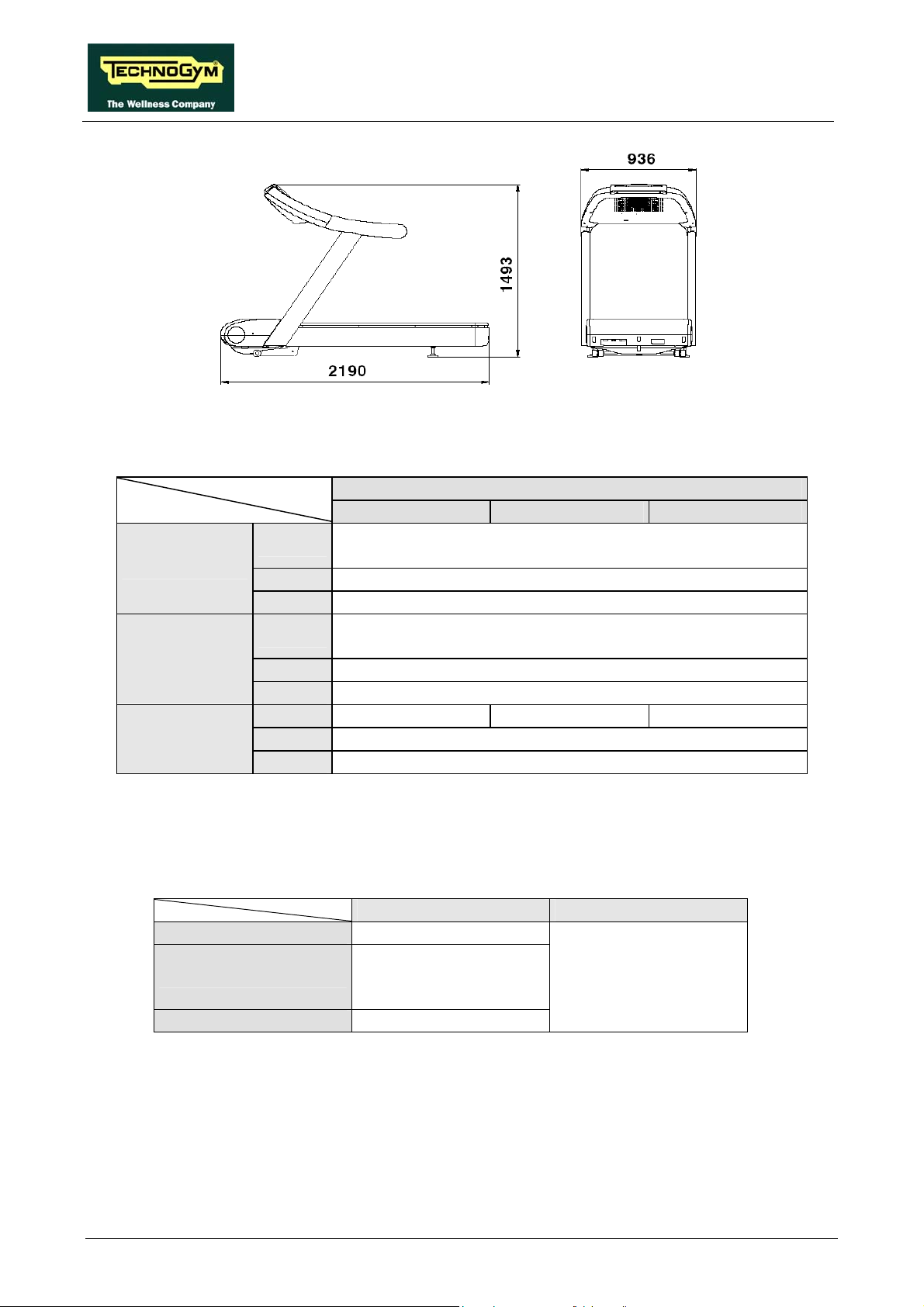
2.2. MECHANICAL CHARACTERISTICS
Width
Length
Height
Weight
93.6 cm - 36.8 in
219 cm - 86.2 in
149.3 cm - 58.8 in
194 kg - 428 lbs
Page 2.1
RUN EXCITE: Service & Maintenance Manual - rev. 1.5
2.3 RI HARACTERISTIC. ELECT CAL C S
500 700 900
180-265 VAC European version
180-242 VAC US version
108-132 VAC USA - Canada version
95-105 VAC Japan version
50 - 60 Hz European version
60 Hz USA version
Mains voltage
Frequency
220 Vac
120 Vac
100 Vac
220 Vac
120 Vac
100 Vac
2300 V 3300 VA – 15 A A 2600 VA – 12 A – 10.5 A
Consumption
220 Vac
120 Vac
100 Vac
2.4. CONFORMITY REGULATIONS
: The machine conforms to the following standards
EMI
Safety
Directives
In a
ddition:
•
Risk category under 93/42/EEC : Class IIA;
• Electrical isolation class under EN60601-1: Class I;
• Applied parts: Type B (not for 500 model);
• Protection rating: IP20.
Europe USA
EN 60601-1-2
EN 60601-1
EN 957-1
SB EN 957-6 class
93/42/CEE
V
ERSION
60 Hz
50 - 60 Hz
1920VA – 16 A
2000VA – 20 A
UL 2601-1
Page 2.2

RUN EXCITE: Service & Maintenance Manual - rev. 1.5
2.5. AMBIENT SPECIFICATIONS
Temperature
Humidity
Operating from 5° to 35° C
Storage from -10 to 70° C
Operating from 30% to 80% non-condensing
Storage from 5% to 85% non-condensing
2.6. PRODUCT CODES
The machine codes take into account all the possible variants and options available for the products.
The machine code, which does not include the Serial Number, consists of 16 alphanumeric
cha ters arrang
rac ed as follows:
Characters description key to values
1,2,3 Machine type: Run Excite
4 Product
5 Type of power supply
6 Type of display
7
8, 9 Color of the frame
10, 11 Color of the paddings
12 Color of the guards
13 Type of TV model
Device for downloading data used by the
Wellness System
version
D44
5 = Run 50
7 = Run 700
9 = Run 900
1 = 110 VAC
T = Wellness TV
N = not availab
= TGS
T
S = smart
L = aluminum A
00 = none
0 = none
0 = none
E = 1, 2, 5, 6,
U = 3, 4, 7, B
Where:
1 = Pal B/G
2 = Pal I
3 = Pal N
4 = NTSC M
5 = Secam E/L
6 = Secam D/K
7 = NTSC M44
8 = Pal D/K
9 = Secam B/G
A = Secam K1
B = Pal M
0
AC 2 = 220 V
display L = LED
le
card
8, 9, A
Page 2.3

RUN EXCITE: Service & Maintenance Manual - rev. 1.5
Characters description key to values
IT = Itali
an
DE = German
FR = French
US = American English
14,15 Language
NL = Dutch
BR = Portuguese
JP = Japanese
UK = British English
ES = Spanish
I = Italy
16 Type of packaging
E = international (standard)
S = international (overseas)
0 = none
The above coding is used for the entire Excite line. For this reason, options not relevant
to the Run machine have also been included.
For example, a possible product code would be
:
D4492LTAL0000UKE
which is interpreted as follows:
D44 9 2 L 0 0 UK E
900 model
Run Excite
T AL 00
guard color
no paddings
aluminum frame color
interfaced to TGS key reader
LED display
220 VAC power supply
no TV model
standard international packing
British English language
Page 2.4

RUN EXCITE: Service & Maintenance Manual - rev. 1.5
2.7. WIRING DIAGRAM
The machine consists of 2 assemblies which are connected together as illustrated below:
Patch
Conn. D
UPPER
ASSEMBLY
TRM-19TRM-20
Patch
Conn. F
Depending on the model, these 2 assemblies can have the different configurations illustrated below.
2.7.1. 900 MODEL
2.7.1.1. EU 220 VAC lower assembly
LOWER
ASSEMBLY
220
VAC
LEDs
CIRCUIT
BRAKER
TRM -02
POWER
ENTRY
SOCKET
TRM -01
Fan
24VDC
Fan
24VDC
TRM -4 4
TRM -0 3
FILTER
TRM -04
RELAY
X
A
X
1
TRM -0 5
8
-
4
6
-
2
Patch
conn. P
0
1
-
TRM -35
X
U
POWER SUPPLY
BOARD
X
V
Patch
conn. L
FE1
X
2
ELEVATION
MOTOR
TRM -08
Patch
conn. G
TRM -AZI O N
X
2
ELEVATION & CUT-OUT
R+,R-
TRM -14
TRM -1 8
V
5
TRM -42
TRM -3 8
BOARD
LIMIT
SWITCH
TRM -10
Patch
conn. M
TRM -3 6
X3
X1
X4
X
6
TRM -AZI O N
X5
X
X
A
E
L
DOWNLOAD
BOARD
X
1
BELT
MOTOR
TRM -0 6
Patch
conn. I
TRM -3 6
3
X
L
2
X
TRM -AZION
U
V
-
W
-
INVERTER
3
-
1
2
7
2
-
1
L
2
L
TRM -AZION
N
K
X
P
R
G
2
Q
A
Encoder
TRM -0 7
Patch
conn. H
A
M
2
-
P
8
LOWER
ASSEMBLY
Patch
conn. R
TRM -4 6
R
R
,
+
H
E
N
O
L
Antenna
inlet
WELLNESS TV
VERSION
TRM -1 9
Page 2.5

2.7.1.2. UL 220 VAC lower assembly
RUN EXCITE: Service & Maintenance Manual - rev. 1.5
220
VAC
LEDs
CIRCUIT
BRAKER
TRM-02A
POWER
ENTRY
SOCKET
TRM-01
Fan
24VDC
Fan
24VDC
TRM-4 4
TRM-03A
FILTER
TRM-04
4
-
8
RELAY
2
-
6
X
A
POWER SUPPLY
X
1
Patch
conn. P
TRM-05
0
-
1
BOARD
FE1
X
E
TRM-35
X
U
X
V
Patch
conn. L
X
2
ELEVATION
MOTOR
TRM-0 8
Patch
conn. G
TRM-AZION
X
2
ELEVATI O N & CUT -O UT
R+,R-
TRM-14
TRM-18
V
5
TRM-42
TRM-38
BOARD
LIMIT
SWITCH
TRM-1 0
Patch
conn. M
TRM-36B
X3
X1
TRM-36A
X9
X
X5
X4
6
TRM-AZION
A
X
DOWNLOAD
L
E
BOARD
X
1
BELT
MOTOR
TRM-06
Patch
conn. I
TRM-36A
X
2
X
U-V
-
W
3
1
3
-
2
L
1
-
L
2
TRM-AZION
L
K
N
X
P
2
R
G
X
A
Q
Encoder
TRM-0 7
Patch
conn. H
TRM-AZION
INVERTER
M
A
2
7
-
2
8
LOWER
ASSEMBLY
Patch
conn. R
TRM-46
R
+
,
R
P
E
H
NOL
Antenna
inlet
WELLNESS TV
VERSION
2.7.1.3. UL 110 VAC lower assembly
AUTOTRANSFORMER
ELEVATION
Patch
conn Q
TRM-50
4
-
8
0
-
1
-
2
6
E
X
POWER SUPPLY
BOARD
Patch
conn. P
TRM-35
U
X
V
X
Patch
conn. L
2
TRM-AZION
X
5
V
110
VAC
LEDs
TRM-03A
CIRCUIT
BRAKER
TRM-02A
POWER
ENTRY
SOCKET
TRM-01
Fan
24VDC
TRM-44
Patch
conn R
FILTER
TRM-04
RELAY
A
X
X
1
MOTOR
TRM-08
Patch
conn. G
2
X
ELEVATI O N & CUT - O UT
R+,R-
BOARD
TRM-14
TRM-18
TRM-42
TRM-38
LIMIT
SWITCH
TRM-10
Patch
conn. M
TRM-36B
X3
X1
TRM-36A
X9
X
X5
X4
6
TRM-AZION
A
L
X
DOWNLOAD
TRM-1 9
E
BOARD
X
1
BELT
MOTOR
TRM-06
Patch
conn. I
TRM-36A
X
2
X
U
-
-
V
W
3
-
1
2
3
1
L
2
-
L
TRM-A ZION
L
N
K
R
P
X
G
2
X
Q
A
Encoder
TRM-07
Patch
conn. H
TRM-AZION
INVERTER
A
M
-
7
2
2
8
LOWER
ASSEMBLY
Patch
conn. R
TRM-46
R
+
,
R
H
P
N
O
E
L
Antenna
inlet
WELLNESS TV
VERSION
Page 2.6
Fan
24VDC
TRM-05
FE1
TRM-19

RUN EXCITE: Service & Maintenance Manual - rev. 1.5
2.7.1.4. Upper assembly: LED version
OWNZONE
RECEIVER
C
1
N
TRM -32
C
N
1
TGS/
SMART
CARD
BOARD
LED BO ARD
C
N
2
FE2
C
N
5
C
N
1
0
CSAFE
BOARD
C
N
1
C
N
6
C
N
1
C
N
1
5
386 BOARD
DIGITAL PLAN BOARD
C
C
N
1
N
7
4
TRM -20
FAN
12 Vdc
TRM-28/B
TRM-2 1TRM -23 TRM-2 4 TRM-3 1
Patch
Conn. O
C
N
8
C
1
N
1
C
N
C
N
C
N
C
N
C
N
9
1
TRM -28
1
6
7
1
3
1
TRM-2 5
Patch
Conn. N
ELEVATION
JOYSTICK
TRM -29
TRM-2 9
SPEED
JOYSTICK
RIGHT
SENSOR
KEYBOARD
HAND
3
Patch
Conn. B
TRM -15
J
SENSOR
BOARD
-
2
J
4
J
TRM-2 6
LEFT
SENSOR
DISPLAY
Patch
Conn. D
TRM-19
FE1
EMERGENCY
BUT TON
Patch
Conn. F
Page 2.7

2.7.1.5. Upper assembly: Wellness TV version
CN11
C
N
1
J1
12 Vdc
TRM-21
0
Patch
Conn Q
HEADPHONE
JACK
DISPLAY
C
N
C
N
C
N
INVERTER
C
N
C
N
4
5
1
3
2
J8
CV-281
TRM-49
AUX INPUT
CN3
LCD
C
BOARD
TGS/
SMART
CARD
BOARD
C
N
1
TRM-32
C
N
8
SPLITTER
AMPLIFIER
N
5
CN15
TRM-48
4
J
1
J
LVDS
BOARD
C
N
1
C
N
BOARD
2
C
N
1
TRM-31
C
N
3
TUNER
CPU
BOARD
C
N
6
J1
CONNECTORS BOARD
C
N
5
1
C
N
1
C
N
1
8
C
N
6
1
TRM-20
CN5CN4
RUN EXCITE: Service & Maintenance Manual - rev. 1.5
OWNZONE
RECEIVER
C
N
1
FAN
Patch
Conn O
TRM-25
TRM-28/B
TRM-28
3
J
SENSOR
BOARD
Patch
Conn N
HAND
ELEVATION
TRM-29
TRM-29
JOYSTICK
SPEED
JOYSTICK
SENSOR
-
J
2
J
4
TRM-26
SENSOR
FE3
KEYBOARDCSAFE
C
N
6
C
N
5
C
N
3
C
9
N
1
C
N
1
1
C
N
4
C
N
3
1
3
J
Patch
Conn B
RIGHT
LEF T
Patch
Conn D
FE1
TRM-19
Patch
Conn F
TRM-47
Patch
Conn R
TRM-46
TRM-15
EMERGENCY
BUTTON
Page 2.8

RUN EXCITE: Service & Maintenance Manual - rev. 1.5
2.7.2. 700 MODEL
2.7.2.1. EU 220 VAC lower assembly
220
VAC
LEDs
CIRCUIT
BRAKER
TRM -02
POWER
ENTRY
SOCKET
TRM -01
Fan
24VDC
Fan
24VDC
TRM -4 4
TRM -0 3
FILTER
TRM -04
RELAY
X
A
X
1
TRM -0 5
8
-
4
6
-
2
Patch
conn. P
0
1
-
TRM -35
X
U
POWER SUPPLY
BOARD
X
V
Patch
conn. L
FE1
X
2
ELEVATION
MOTOR
TRM -08
Patch
conn. G
TRM -AZI O N
X
2
ELEVATION & CUT-OUT
R+,R-
TRM -14
TRM -1 8
V
5
TRM -42
TRM -3 8
BOARD
LIMIT
SWITCH
TRM -10
Patch
conn. M
TRM -3 6
X3
X1
X4
X
6
TRM -AZI O N
X5
X
X
A
E
L
DOWNLOAD
BOARD
X
1
BELT
MOTOR
TRM -0 6
Patch
conn. I
TRM -3 6
3
X
L
2
X
TRM -AZION
U
V
-
W
-
INVERTER
3
-
1
2
7
2
-
1
L
2
L
TRM -AZION
N
K
X
P
R
G
2
Q
A
Encoder
TRM -0 7
Patch
conn. H
A
M
2
-
8
LOWER
ASSEMBLY
Patch
conn. R
TRM -4 6
R
R
,
+
P
H
E
N
O
L
Antenna
inlet
WELLNESS TV
VERSION
TRM -1 9
Page 2.9

2.7.2.2. UL 220 VAC lower assembly
RUN EXCITE: Service & Maintenance Manual - rev. 1.5
220
VAC
LEDs
CIRCUIT
BRAKER
TRM-02A
POWER
ENTRY
SOCKET
TRM-01
Fan
24VDC
Fan
24VDC
TRM-4 4
TRM-03A
FILTER
TRM-04
4
-
8
RELAY
2
-
6
X
A
POWER SUPPLY
X
1
Patch
conn. P
TRM-05
0
-
1
BOARD
FE1
X
E
Patch
conn. L
TRM-35
X
U
X
V
2
ELEVATION
MOTOR
TRM-0 8
Patch
conn. G
TRM-AZION
X
2
ELEVATI O N & CUT -O UT
R+,R-
TRM-14
X
V
5
TRM-42
TRM-38
BOARD
TRM-18
LIMIT
SWITCH
TRM-1 0
Patch
conn. M
TRM-36B
X3
X1
TRM-36A
X9
X
X5
X4
6
TRM-AZION
A
X
DOWNLOAD
L
E
BOARD
X
1
BELT
MOTOR
TRM-06
Patch
conn. I
TRM-36A
X
2
X
U-V
-
W
3
1
3
-
2
L
1
-
L
2
TRM-AZION
L
K
N
X
P
2
R
G
X
A
Q
Encoder
TRM-0 7
Patch
conn. H
TRM-AZION
INVERTER
M
A
2
7
-
2
8
LOWER
ASSEMBLY
Patch
conn. R
TRM-46
R
+
,
R
P
E
H
NOL
Antenna
inlet
WELLNESS TV
VERSION
2.7.2.3. UL 110 VAC Lower assembly
AUTOTRANSFORMER
ELEVATION
Patch
conn Q
TRM-50
4
-
8
0
-
1
-
2
6
X
E
POWER SUPPLY
BOARD
Patch
conn. P
TRM-35
X
U
X
V
Patch
conn. L
2
TRM-AZION
X
V
5
R+,R-
TRM-38
110
VAC
LEDs
TRM-03A
CIRCUIT
BRAKER
TRM-02A
POWER
ENTRY
SOCKET
TRM-01
Fan
24VDC
TRM-44
Patch
conn R
FILTER
TRM-04
RELAY
X
A
X
1
LIMIT
MOTOR
TRM-08
Patch
conn. G
SWITCH
TRM-10
Patch
conn. M
TRM-36B
X
2
ELEVATI O N & CUT - O UT
BOARD
X1
TRM-14
TRM-18
TRM-42
TRM-36A
X3
X9
X4
X
6
TRM-AZION
X5
X
TRM-1 9
X
A
L
E
DOWNLOAD
BOARD
X
1
BELT
MOTOR
TRM-06
Patch
conn. I
TRM-36A
U
3
-32
1
L
X
L
N
2
X
X
Q
TRM-07
TRM-AZION
-
V
-
W
INVERTER
-
7
2
2
1
-
L
2
TRM-A ZION
K
P
R
G
2
A
Encoder
Patch
conn. H
+
A
M
P
H
E
N
8
LOWER
ASSEMBLY
Patch
conn. R
TRM-46
R
,
R
O
L
Antenna
inlet
WELLNESS TV
VERSION
24VDC
Page 2.10
Fan
TRM-05
FE1
TRM-19

RUN EXCITE: Service & Maintenance Manual - rev. 1.5
2.7.2.4. Upper assembly, LED version
OWNZONE
RECEIVER
C
N
1
C
FE2
TRM -3 2
C
N
1
TGS/
SMART
CARD
BOARD
LED BOARD
N
2
C
N
5
C
N
1
0
CSAFE
BOARD
C
N
1
C
N
6
C
N
1
C
N
5
1
386 BOARD
DIG ITAL PLAN BOARD
C
N
1
C
N
7
4
TRM-2 0
C
N
9
TRM -2 1TRM-2 3 TRM-24 TRM -3 1
C
N
8
KEYBOARD
Patch
Conn. B
C
N
C
C
1
TRM -1 5
FAN
12 Vdc
TRM -2 8/ B
Patch
Conn. O
N
1
1
TRM-2 8
N
1
3
Patch
Conn. N
TRM -2 5
RIGHT
SENSOR
HAND
3
J
SENSOR
J
J
-
2
4
TRM -2 6
BOARD
LEFT
SENSOR
DISPLAY
Patch
Conn. D
TRM-1 9
FE1
EMERGENCY
BUTTO N
Patch
Conn. F
Page 2.11

2.7.2.5. Upper assembly: Wellness TV version
DISPLAY
C
C
C
INVERTER
C
C
N
4
5
N
N
1
3
N
2
N
CV-281
J8
TRM-32
LCD
C
5
N
TRM-49
1
J
AUX INPUT
BOARD
CN3
TGS/
SMART
CARD
BOARD
C
N
1
C
N
8
SPLITTER
AMPLIFIER
CN15
TRM-48
J
4
CN5CN4
LVDS
BOARD
C
N
1
3
N
C
BOARD
TUNER
CPU
C
N
2
TRM-20
BOARD
C
1
N
TRM-31
6
N
C
J1
CONNECTORS BOARD
C
N
5
1
C
1
N
C
1
N
8
J1
N
C
6
1
CN11
N
C
0
1
HEADPHONE
RUN EXCITE: Service & Maintenance Manual - rev. 1.5
OWNZONE
RECEIVER
C
N
1
FAN
12 Vdc
TRM-21
C
5
N
3
J
FE3
Patch
Conn Q
JACK
KEYBOARDCSAFE
C
6
N
C
3
N
N
C
4
N
C
3
1
Patch
Conn B
Patch
Conn O
TRM-25
TRM-28/B
TRM-28
HAND
3
J
SENSOR
BOARD
Patch
Conn N
RIGHT
SENSOR
2
J
4
-
J
TRM-26
LEFT
SENSOR
Patch
Conn D
FE1
TRM-19
Patch
Conn F
TRM-47
Patch
Conn R
TRM-46
TRM-15
EMERGENCY
BUTTON
Page 2.12

RUN EXCITE: Service & Maintenance Manual - rev. 1.5
2.7.3. 500 MODEL
2.7.3.1. EU 220 VAC lower assembly
220
VAC
LEDs
CIRCUIT
BRAKER
TRM -02
POWER
ENTRY
SOCKE T
TRM -01
Fan
24VDC
TRM-4 4
TRM -03
FILTER
TRM -04
4
8
-
RELAY
0
6
-
2
A
X
POWER SUPPLY
X
1
Patch
conn. P
1
-
BOARD
TRM -35
X
X
V
Patch
conn. L
U
X
2
ELEVATION
MOTOR
TRM -08
Patch
conn . G
TRM -AZION
2
X
ELEV A TI ON & C UT-OUT
R+,R-
TRM-1 4
TRM -18
5
V
TRM-4 2
TRM -38
BOARD
LIMIT
SWITCH
TRM -10
Patch
conn. M
TRM -36
X3
X1
X4
X
6
TRM -AZION
X5
X
A
X
E
L
DOWNLOAD
BOARD
1
X
BELT
MOTOR
TRM -06
Patch
conn. I
TRM -36
3
1
L
X
2
X
TRM -AZION
V
-
U
W
-
INVERTER
3
-
2
7
2
L
1
-
2
L
TRM -AZION
K
N
P
X
2
G
R
Q
A
Patch
conn.. H
M
A
P
8
2
-
LOWER
ASSEMBLY
R
,
+
R
H
N
E
L
O
Fan
24VDC
TRM -05
FE1
TRM -19
Page 2.13

2.7.3.2. UL 220 VAC lower assembly
RUN EXCITE: Service & Maintenance Manual - rev. 1.5
220
VAC
LEDs
CIRCUIT
BRAKER
TRM-02A
POWER
ENTRY
SOCKET
TRM-01
Fan
24VDC
Fan
24VDC
TRM-44
TRM-03A
FILTER
TRM-04
RELAY
X
A
1
X
TRM-05
8
-
4
-
2
Patch
conn. P
1
-
0
6
X
E
X
POWER SUPPLY
BOARD
X
Patch
conn. L
FE1
TRM-35
U
X
V
2
V
ELEVATION
MOTOR
TRM-08
Patch
conn. G
TRM-AZION
2
X
ELEVATION & C U T-OU T
R+,R-
TRM-14
TRM-18
5
TRM-42
TRM-38
BOARD
LIMIT
SWITCH
TRM-10
Patch
conn. M
TRM-36B
X3
X1
TRM-36A
X9
X
X5
X4
6
TRM-AZION
L
A
X
DOWNLOAD
E
BOARD
1
X
BELT
MOTOR
TRM-06
Patch
conn. I
TRM-36A
1
3
L
X
2
X
X
TRM-AZION
-
U
W
-
V
2
3
2
L
L
-
1
2
TRM-AZION
K
N
R
P
X
2
G
A
Q
Patch
conn.. H
INVERTER
A
P
M
-
7
8
2
LOWER
ASSEMBLY
R
R
,
+
N
E
H
L
O
2.7.3.3. UL 110 VAC Lower assembly
AUTOTRANSFORMER
Patch
conn Q
TRM-50
4
-
8
0
-
1
2
-
6
X
POWER SUPPLY
BOARD
Patch
conn. P
110
VAC
LEDs
TRM-03A
CIRCUIT
BRAKER
TRM-02A
POWER
ENTRY
SOCKET
TRM-01
Fan
24VDC
TRM-44
Patch
conn R
FILTER
TRM-04
RELAY
X
A
X
1
E
TRM-35
X
U
X
V
2
Patch
conn. L
ELEVATION
MOTOR
TRM-08
Patch
conn. G
TRM-AZION
X
2
ELEVATI O N & CUT-O UT
R+,R-
TRM-14
X
V
5
TRM-42
TRM-38
BOARD
TRM-18
LIMIT
SWITCH
TRM-1 0
Patch
conn. M
TRM-36B
X3
X1
TRM-36A
X9
X
X5
X4
6
TRM-AZION
X
A
DOWNLOAD
TRM-19
L
E
BOARD
X
1
BELT
MOTOR
TRM-06
Patch
conn. I
TRM-36A
3
X
L
X
2
X
TRM-AZION
U
-
V
-
W
1
-
3
2
2
L
1
-
L
2
TRM-AZION
N
K
X
P
R
G
2
Q
A
Patch
conn.. H
INVERTER
A
M
7
-
2
8
LOWER
ASSEMBLY
R
+
,
R
P
H
E
N
O
L
Page 2.14
Fan
24VDC
TRM-05
FE1
TRM-19

RUN EXCITE: Service & Maintenance Manual - rev. 1.5
2.7.3.4. Upper assembly, LED version
CSAFE
BOARD
N
C
1
TRM-31
N
C
1
TRM-32
C
1
N
TGS/
SMART
CARD
BOARD
C
N
C
3
N
N
C
386 BOARD
DIS PLAY BOARD
2
DISPL AY
C
N
7
N
C
C
N
6
TRM-28
8
9
KEYBOARD
HFU
RECEIVER
TRM-20
Patch
Conn B
FE1
TRM-15
EMERGENCY
BUTTON
Patch
Conn D
TRM-19
Patch
Conn F
Page 2.15

2.8. WIRING
Power entry
socket
Faston Neutral Blue 2
Faston Line Brown 4
Circuit breaker
terminal
1 Neutral Blue N
3 Line Brown P
Circuit breaker
terminal
1 Neutral Blue N
3 Line Brown P
Filter
terminal
N’ Neutral
P’ Line
Patch
L
1 24 Vdc power supply Red
2 Gnd Black
RUN EXCITE: Service & Maintenance Manual - rev. 1.5
TRM-02: High voltage cable
Power entry socket – Circuit breaker
Signal Color Circuit breaker
terminal
TRM-03: High voltage cable
Circuit breaker - Filter
Signal Color Filter
terminal
TRM-03A: High voltage cable (UL)
Circuit breaker - Filter
Signal Color Filter
terminal
TRM-04: High voltage cable
Filter – Relay – Power supply board
Signal Color Relay Power supply
Blue 4 -
Blue - 4
Brown 8 Brown - 2
board
XA
TRM-05: Motor compartment fan cable
Patch connector - Fan
Signal Color Fan
internally
connected cable
Page 2.16

RUN EXCITE: Service & Maintenance Manual - rev. 1.5
TRM-06: Belt motor cable
Patch connector - Motor
Patch
I
1 U Black 1
2 V Black 2
3 W Black 3
4 thermal cutout + Black 4
5 thermal cutout - Black 5
6 GND Black 6
Signal Color Motor
TRM-07: Encoder cable
Patch connector - Encoder
Patch
H
1 Gnd Red 1
2 Out 1 Red 3
3 +5 Vdc power supply for encoder Red 4
4 Out 2 Red 5
Signal Color Encoder
TRM-08: Elevation motor cable
Patch connector – Elevation motor
Patch
G
1 Motor - Black
2 Motor + Black
4 Gnd Black
5 +5 Vdc power supply for encoder Red
6 Pulses White
Signal Color Elevation motor
TRM-10: Limit switch cable
Patch connector – Limit switch
Patch
M
1 Reference Brown COM 1
2 Contact White NC 2
Signal Color Limit switch
internally
connected cable
internally
connected cable
Page 2.17

RUN EXCITE: Service & Maintenance Manual - rev. 1.5
TRM-14: Inverter power supply cable
Relay - Inverter
Relay Signal Color Inverter
2 Line Blue L1
6 Neutral Brown L2
TRM-15: Emergency button cable
Patch connector - Microswitch
Patch
B
1 Emergency Brown C 2 Reference White - C
- Bridge Black NC NC
Signal Color Micro 1 Micro 2
TRM-18: Electrical box power supply cable
Download board – Elevation board – Power supply board
Download
board
X2
2 Gnd +12 Vdc
3 Gnd +5 Vdc Black - - 9
4 -sensing +5 Vdc White - - 8
6 +12 Vdc
7 + 5 Vdc Red - - 4
8 +sensing +5 Vdc Yellow - - 3
9 Emergency Purple - 2 10 Reset Blue - 4 11 +12 Vdc isolated Red - 1 -
12
- Gnd +24 Vdc Brown 2 - 10
- +24 Vdc Pink 1 - 5
Signal Color
Gray 4 - Gray - - 7
Orange 3 - Orange - - 2
Gnd +12 Vdc
isolated
Black - 3 -
Elevation board
X1 X4
Power supply
board
XU
Page 2.18

RUN EXCITE: Service & Maintenance Manual - rev. 1.5
TRM-19: Cable connecting upper and lower assemblies
Patch connectors –Download Board
Patch
D
1 NC Green-White 1
2 NC Green 2
3 Digital Gnd Orange-White 3
4 Download Blue 4
5 Reset Blue-White 5
6 Digital Gnd Orange 6
7 485 Tx/Rx + Brown-White 7
8 485 Tx/Rx - Brown 8
Patch
F
2 Gnd +12 Vdc Gray 2
3 Gnd +5 Vdc Black 3
4 -sensing +5 Vdc White 4
6 +12 Vdc Orange 6
7 +5 Vdc Red 7
8 +sensing +5 Vdc Yellow 8
9 Emergency Purple 9
10 Reset Blue 10
11 +12 Vdc isolated Red 11
12 Gnd +12 Vdc isolated Black 12
Signal Color Download Board
Signal Color Download board
TRM-20: Display communication and power supply cable
Patch connector – Digital Plan Board – Patch connector
2 Gnd +12 Vdc Gray 2 - 3 Gnd +5 Vdc Black 3 - 4 -sensing +5 Vdc White 4 - 6 +12 Vdc Orange 6 - 7 +5 Vdc Red 7 - 8 +sensing +5 Vdc Purple 8 - -
9 Emergency Purple - 4 10 Reset Blue - 5 11 +12 Vdc isolated Red - 1 -
12 Gnd +12 Vdc isolated
- HW Emergency Gray - 2
- SW Emergency Gray - 3
Black - 6 Black - - 1
Digital Plan Board Patch F Signal Color
CN7 CN9
XQA
X1
Patch
B
2
Page 2.19

RUN EXCITE: Service & Maintenance Manual - rev. 1.5
TRM-20: Display communication and power supply cable
Patch connector – Digital Plan Board – Patch connector
Patch D Signal Color Digital Plan Board
CN14
1 NC Green-White 1
2 NC Green 2
3 Digital Gnd Orange-White 3
4 Download Blue 4
5 Reset Blue-White 5
6 Digital Gnd Orange 6
7 485 Tx/Rx + Brown-White 7
8 485 Tx/Rx - Brown 8
TRM-21: Display fan cable
Digital Plan Board - Fan
Digital Plan
Board
CN8
1 24 Vdc power supply Red
2 Gnd Black
Signal Color Fan
TRM-23: LED board digital signal cable
Digital Plan Board – LED Board
Digital Plan
Board
CN5
1 Digital #1 Flat cable 1
… … … …
16 Digital #16 Flat cable 16
Signal Color LED Board
internally
connected cable
CN2
TRM-24: LED power supply board
Digital Plan Board – LED Board
Digital Plan
Board
CN6
1 Gnd (digital) Black 1
2 Gnd (power) Gray 2
3 +5 Vdc power supply (digital) Red 3
4 +5 Vdc power supply (power) Orange 4
Signal Color LED Board
CN1
Page 2.20

RUN EXCITE: Service & Maintenance Manual - rev. 1.5
TRM-25: Hand sensor board cable
Digital Plan Board – Hand Sensor Board
Digital Plan
Board
CN13
1 +5 Vdc power supply Brown 2
4 Board Reset Yellow -
5 Pulse out Green 3
6 Reference White 1
ATTENTION: the cable sheath contains a circuit which, in response to a reset signal received from
the Digital Plan board, is able to reset the hand sensor board by removing and subsequently reapplying the supply voltage.
Hand sensor
board
J2 - J4
1 Right sensor signal Yellow up -
2 Sensor signal reference White down -
4 Left sensor signal Brown - up
5 Sensor signal reference Green - down
Signal Color Hand sensor
TRM-26: Sensor Cable
Hand Sensor Board - Sensors
Signal Color
board
J3
Sensors
RH LH
TRM-28: OwnZone receiver cable (extension)
Digital Plan Board – Patch connectors
Digital Plan
Board
CN11
1 Power supply White-Green 2 -
2 I2C clock Blue - 1
3 I2C data Green - 2
4 External reset Orange 3 -
7 Pulse (beat to beat) Brown 4 -
8 Gnd White-Blue 1 -
Signal Color Patch O Patch
N
Page 2.21

RUN EXCITE: Service & Maintenance Manual - rev. 1.5
TRM-28/B: OwnZone receiver cable
Patch connectors – OwnZone Receiver
OwnZone
Receiver
CN1
1 I2C clock Blue - 1
2 I2C data Green - 2
3 Pulse (beat to beat) Brown 4 -
4 Power supply White 2 -
5 Gnd Yellow 1 -
9 External Reset Orange 3 -
Signal Color Patch O Patch
N
TRM-29: Joystick cable
Digital Plan Board - Microswitch
Digital Plan
Board
CN16 or CN17
1 Value 1 reference White - C
2 Value 1 (incline or speed -) Brown - NO
3 Value 2 reference Green C -
4 Value 2 (incline or speed +) Yellow NO -
Signal Color Micro + Micro -
TRM-31: CSafe cable board
Digital Plan Board – CSafe Board
Digital Plan
Board
CN15
1 Digital #1 Flat cable 1
… … … …
14 Digital #14 Flat cable 14
Signal Color CSafe Board
CN1
TRM-32: TGS/smart card Cable
Digital Plan Board – TGS/Smart Card Board
Digital Plan
Board
CN10
1 +12 Vdc power supply Yellow 1
3 Rx White 8
5 Tx Green 7
9 Gnd Brown 3
Signal Color TGS/Smart Card
Board
CN1
Page 2.22

RUN EXCITE: Service & Maintenance Manual - rev. 1.5
TRM-36: Belt motor + Limit switch cable
Patch connectors – Belt motor – Limit switch
Patch
I
1 U Brown U -
2 V White V -
3 W Black W -
4 Thermal cutout + Red - 4
5 Thermal cutout - Red - 3
6 Gnd Gray PE -
Patch
M
1 Limit switch contact Brown - 5
2 Limit switch contact reference White - 6
Signal Color Inverter Elevation
Signal Color Inverter Elevation
TRM-36A: Belt motor (UL)
Patch connectors – Inverter – Elevation board – Power supply board
Patch
I
1 V Brown V -
2 U White U -
3 W Black W -
4 Thermal cutout + Red - 4
5 Thermal cutout - Red - 3
6 Gnd Gray PE -
Power supply
board
XE
2 Vdc reference Black - 2
1 +15 Vdc power supply White - 1
Signal Color Inverter Elevation
Signal Color Inverter Elevation
TRM-36B: Limit switch cable (UL)
Elevation board – Patch connectors
Elevation
board
X3
5 Limit switch contact Brown 1
6 Limit switch contact reference White 2
Signal Color Patch
board
X3
board
X3
board
X9
board
X9
M
Page 2.23

Power supply
board
XV2
Power supply
Download Board
XPRG2
Power supply
RUN EXCITE: Service & Maintenance Manual - rev. 1.5
TRM-38: Motor compartment fan cable (extension)
Power supply board – Patch connectors - Inverter
Signal Color Inverter Patch
1 24 Vdc power supply White 32 - -
- - Red 31 1 1
2 Gnd Black - 2 2
P
Patch
L
TRM-42: Download board power supply cable
Power supply board – Download Board
Signal Color Download Board
board
XV5
2 +5 Vdc power supply for display Red 1
3 Gnd Black 2
TRM-43: Inverter Serial Cable
Download board - Inverter
Signal Color Inverter
1 Digital #1 Flat cable 1
… … … …
14 Digital #14 Flat cable 14
TRM-44: Power supply LED cable
Power supply board - LED
Signal Color LED
board
CN1
3 +12 Vdc Green
4 +12 Vdc reference Yellow
7 +5 Vdc Gray
8 +5 Vdc reference Pink
9 +24 Vdc reference White
10 +24 Vdc Brown
XALE
12V LED
Green
5V LED
Green
24V LED
Green
Page 2.24

RUN EXCITE: Service & Maintenance Manual - rev. 1.5
TRM-48: Inlet DVD video cable
Connectors board – AUX input board
Connectors
board
CN1
1 Color Red 1
2 Left audio IN White 2
3 Gnd Shield 3
4 Right audio IN Red 4
5 Gnd Shield 5
6 Video IN Yellow 6
7 Gnd Shield 7
8 Commutation White 8
Signal Color AUX input
TRM-49: Inlet CD cable
Connectors board – AUX input board
Connectors
board
CN15
1 Right audio IN Red 1
2 Gnd Shield 2
3 Left audio IN White 3
4 Gnd Shield 4
Signal Color AUX input
TRM-50: 110V power supply cable
Patch conn. Q – Patch conn. R - Filter
Patch conn. Q Signal Color P.E. Patch conn.
1 Gnd Giallo/verde Eyelet - 2 Fase 110V Marrone - 1 3 Neutro 110V Blu - 2 4 Fase 220V Marrone - - N
5 Neutro 110V Blu - P
CV-281: LCD inverter power supply cable
CPU board – LCD inverter
CPU board
CN5
1 +12 Vdc power supply Black 11
2 Reference Black 2
3 +3.3 Vdc power supply Black 4
4 Reference Black 3
5 +12 Vdc power supply Black 12
Signal Color LCD inverter
board
J4
board
J1
Filter
R
terminal
CN1
Page 2.25

RUN EXCITE: Service & Maintenance Manual - rev. 1.5
TRM-AZION: Inverter + elevation motor cable
Download board - Inverter
Inverter Signal Color Elevation board
5 Input signal reference -
6
15 Direction control Brown 2
35 Enable motor movement Green 3
18 Pulses Yellow 5
3 Belt motor thermal cutout Gray 6
17 Limit switch state Pink 7
7
13
34
Inverter Signal Color Download Board
27 Link + Red 2
28 Link - Black 1
Patch
G
1 Mot+ Brown 1
2 Mot- Blue 2
4 Gnd White-Yellow 4
5 +5 Vdc power supply Yellow-Brown 5
6 Pulses White-Gray 6
Patch
H
1 Gnd White-Green - 2
2 Out 1 Red-Blue 10
3
- 9 -
-
4 Out 2 Purple 12 -
Input signal reference
Input signal reference White 1
Output signal reference Blue 8
Output signal reference
Signal Color Elevation board
Signal Color Inverter Elevation
+5 Vdc power supply
White
Gray-Pink Gray-Pink 9
Gray-Pink
Blue
Blue
X5
-
- Output signal reference
-
-
-
XLNK
X2
board
X6
1
11 -
Page 2.26

RUN EXCITE: Service & Maintenance Manual - rev. 1.5
(
)
3. PRINCIPLES OF OPERATION
3.1. BLOCK DIAGRAM
The machine block diagram is illustrated in the figure below:
DISPLAY
CARDIO
RECEIVER
Antenna
inlet
(W.TV only)
Lower
assembly
fan
TGS/
SMART CARD
BOARD
CSAFE
BOARD
POWER SUPPLY
BOARD
DIS PLAY BOARDS
DOWNLOAD
BOARD
USER FAN
(not on 500)
HAND
SENSOR
BOARD
(not on 500)
KEYBOARD
ELEVATION & CUT-
OUT BOARD
ELEVATION
JOYSTICK
(900 only)
SPEED
JOYSTICK
(900 only)
R SENSOR
(not on 500)
L SENSOR
(not on 500)
EMERGENCY
BUTTON
ELEVATION
MOTOR
Ele ctronic
assembly
AUTOTRANSFORMER
(110V only)
fan
3.1.1. DISPLAY BOARDS
3.1.1.1. 500 LED model
The display contains:
FILTER
CIRCUIT
BREAKER
POWER
ENTRY
SOCKET
110/220 VAC
INVERTER
RELAY
ELECTRONI C ASSEMBLY
LIMIT
SWITCH
BELT
MOTOR
Encoder
not on 500
Page 3.1

RUN EXCITE: Service & Maintenance Manual - rev. 1.5
• 386
BOARD
This is the circuit board which comprises the CPU, a 386 microprocessor, its logic circuits and
a FLASH EPROM containing the operating program for the machine.
• D
ISPLAY BOARD
This is the heart of the display: this board acts as the interconnection hub for all the
components of the display, and serves as the point of connection with the electrical box. In
particular, its functions are:
receives commands of the machine program from the 386 Board;
>
>
sends to the 386 Board the signals received from:
- Keyboard;
- Cardio receiver;
- TGS/Smart Card Board;
- CSafe Board.
distributes to the display the voltages received from the Power Supply Board;
>
>
houses the backup battery which maintains the RAM memory on the 386 board;
>
exchanges, over the RS-485 serial link to the inverter, and via the Download Board,
commands for controlling the belt and elevation motors;
>
illuminates the LEDs and 7-segment displays used for the exercise feedback.
The board includes the following indicator LEDs:
LED name Color Description
DL1 green
if ON the +5 Vdc supply is correctly
stabilized by the display board.
if ON the +12 Vdc supply provided by the
DL2 green
Power Supply Board, correctly reaches the
board.
if ON the +5 Vdc supply provided by the
DL3 orange
Power Supply Board, correctly reaches the
board.
and 2 jumpers:
Jumper Name Setting Description
JP1 close
if short-circuited, keeps the memory powered
when the machine is off.
JP2 open if short-circuited, resets the circuit board.
3.1.1.2. 700 / 900 LED models
The display contains:
• 386
BOARD
This is the circuit board which comprises the CPU, a 386 microprocessor, its logic circuits and
a FLASH EPROM containing the operating program for the machine.
• D
IGITAL PLAN BOARD
Page 3.2

RUN EXCITE: Service & Maintenance Manual - rev. 1.5
This is the heart of the display: this board acts as the interconnection hub for all the
components of the display, and serves as the point of connection with the electrical box. In
particular, its functions are:
>
receives commands of the machine program from the 386 Board;
>
sends to the 386 Board the signals received from:
- Keyboard;
- Cardio receiver;
- Hand Sensor Board;
- TGS/Smart Card Board;
- CSafe Board;
- Speed and elevation joystick (900 model only).
>
Distributes to the display the voltages received from the Power Supply Board;
>
Controls the User Fan;
>
Houses the backup battery which maintains the RAM memory on the 386 board;
>
Exchanges, over the RS-485 serial link to the inverter, and via the Download Board,
commands for controlling the belt and elevation motors.
The board includes the following indicator LEDs:
LED name Color Description
DL1 not assembled DL2 not assembled -
DL3 green
if ON the +5 Vdc supply is correctly
stabilized by the Digital Plan board.
if ON the +5 Vdc supply provided by the
DL4 orange
Power Supply Board, correctly reaches the
board.
if ON the +12 Vdc supply provided by the
DL5 green
Power Supply Board, correctly reaches the
board.
and 2 jumpers:
Jumper Name Setting Description
JP1 open if short-circuited, resets the circuit board.
JP2 close
if short-circuited, keeps the memory powered
when the machine is off.
Page 3.3

RUN EXCITE: Service & Maintenance Manual - rev. 1.5
• LED B
OARD
Contains the circuits for the LEDs and the alphanumeric displays. The board includes the
following indicator LEDs:
LED name Color Description
LED1 green
if ON the +5 Vdc supply is correctly
stabilized by the Digital Plan board.
if ON the +5 Vdc supply provided by the
LED 2 yellow
Power Supply Board, correctly reaches the
board.
3.1.1.3. 700E / 900E models (Wellness TV )
The display includes the boards:
• C
ONNECTORS BOARD
This board acts as the interconnection hub for all the components of the display, and serves as
the point of connection with the electrical box. It includes connectors for the following:
Cardio receiver;
>
>
Hand sensor board;
>
CSafe board;
>
Speed and elevation Joystick (900 model only);
>
User fan;
>
Emergency button;
>
AUX input board;
>
Antenna signal;
>
Voltage received from the power supply board;
>
RS-485 serial link to the inverter.
It has a connector for linking to the CPU board, to transfer the collected signals.
The board includes the following indicator LED:
LED name Color Description
D10 red
if ON the +12 Vdc supply from the power
supply board, correctly reaches the board.
and a faston:
Name Description
SHLD: denotes a ground node on the circuit
board.
• CPU
BOARD
J2
This is the heart of the display: it is the circuit board which incorporates the CPU, a
microprocessor, its control logic, the FLASH EPROM containing the operating program of the
machine, and the tuner for the audio and video channels. Through the connector board, it
receives signals from the various machine components.
This circuit board is directly connected to:
Page 3.4

RUN EXCITE: Service & Maintenance Manual - rev. 1.5
>
TGS/Smart Card board;
>
LVDS board;
>
Keyboard;
>
Headphone Jack;
>
Splitter / amplifier;
>
Power supply inverter for LCD.
The main functions of the board are:
>
Distributes to the display the voltages received from the Power Supply Board;
>
Controls the User Fan;
>
Houses the backup battery which maintains the RAM memory on the 386 board;
>
Exchanges, over the RS-485 serial link to the inverter, and via the Download Board,
commands for controlling the belt and elevation motors;
>
Tuning of audio and video channels;
>
Manages the display of images on the LCD.
The board includes the following 2 jumpers:
Jumper Name Setting Description
JP1 open if short-circuited, enables a reset of the microprocessor.
CN2 open if short-circuited, enables writing to the flash EPROM.
and a 3-pin connector (CN18) that can be used for testing the power supplies output by the
board: 0 Vdc (ground), 5Vdc and 3.3 Vdc.
• S
PLITTER / AMPLIFIER
This device amplifies the signal received from the antenna, separating the audio channel from
the video channel, which it sends to the tuner.
• LVDS
BOARD
It is an RGB buffer board with six bits per color, that interfaces the video signals sent from the
CPU board to the LCD.
• LCD
INVERTER
This device powers the LCD display segments. It receives DC power supplies (12 Vdc and 3.3
Vdc) from the CPU board, and generates the AC voltage (300 Vac) needed to supply the LCD.
• AUX
INPUT CONNECTORS
This board provides 3 RC connectors and one mini DIN connector for interfacing external
audio visual devices to the machine. An input on this board allows the external source to be
displayed on the LCD base band.
Page 3.5

RUN EXCITE: Service & Maintenance Manual - rev. 1.5
• H
EADPHONE JACK
Two jacks are provided on the machine for connecting headphones. The two jacks are
connected in parallel to a stereo output of the CPU board. In addition to the audio signals, the
connector also includes a sense signal for routing the output to the headphones, if installed. The
sense contact is NC and opens when the headphone jack is plugged in.
3.1.2. CSAFE BOARD
This board makes available a communication port, on 2 externally accessible connectors, which can
be used for connecting compatible CSafe devices such as the CardioTheater readers.
These connectors can also be interfaced, using a special cable, to an external PC for programming
the FLASH EEPROM.
3.1.3. TGS/SMART CARD BOARD
This board enables the machine to read the TGS key or Smart Card inserted by the user for
performing workouts programmed with the Wellness System. The machine can be interfaced with
either a TGS key or Smart Card reader, hence its name TGS/Smart Card Board.
3.1.4. HAND SENSOR BOARD
This is the board which manages the hand sensors, interfacing them with the Digital Plan Board. It
processes the analog signal received from the sensors and outputs one positive logic pulse for each
heart beat that is detected. The signal level is normally 5 Vdc; it goes to 0 Vdc when the user’s
hands are placed on the contacts, and a 5 Vdc pulse (having a width of approximately 30 msec) is
output at each detected heart beat.
3.1.5. CARDIO RECEIVER
This board manages the signal received from the telemetric transmitter used by the person
exercising, and interfaces it with the Digital Plan Board. The model used is the OnwZone. There are
2 types of receiver:
• HFU Model (on 500 models): this is the standard product. It receives the power supply signal
from the display board and outputs a negative logic pulse for every heart beat that is detected:
the signal level is normally 5 Vdc, with a pulse at 0 Vdc (having a width of approximately 30
msec) at each heart beat.
• OwnZone Model (on 700 and 700E models): this is a special receiver model produced by
Polar, equipped with a microprocessor and capable of independently detecting the heart rate. It
receives the power supply signal from the Digital Plan board, to which it is connected by:
>
a pulse signal: a pulse for every heart beat that is detected;
>
a reset signal: an external reset signal provided by the digital plan board every times an
exercise is started;
>
a serial signal on a I2C protocol.
The receivers reception area is approximately a circle with a 1 m radius. If there is electromagnetic
noise (produced by high voltage lines, radio transmitters, monitors, motors etc.) within this area, the
receiver becomes saturated and no longer receives any signal.
Page 3.6

RUN EXCITE: Service & Maintenance Manual - rev. 1.5
3.1.6. JOYSTICK
Only on the 900 models, there are 2 joysticks for adjusting the elevation and the speed. These
joysticks in fact send the Digital Plan Board the same signals produced by pressing the “+” and “-”
or “↑“ and “↓“ keys on the keyboard.
3.1.7. EMERGENCY SWITCH
This is the user safety device. It consists of 2 microswitches connected in series, which can be
tripped either by pressing the emergency button or by pulling a cord clipped to the garment of the
person exercising.
The emergency switch, which provides a NC contact, acts on both the Digital Plan Board and the
Elevation + Cut-out Board which uses it to control the relay that supplies power to the inverter.
When the emergency is tripped the relay removes the supply voltage from the inverter, causing the
tread belt and elevation motors to stop. The digital plan board also detects tripping of the
emergency switch, upon which it interrupts the exercise and shows the “EMERGENCY STOP”
message on the display.
To resume normal machine operation, it is necessary to press the “Clear” button.
3.1.8. RELAY
This is a power relay with NC contact, which disconnects the supply voltage to the inverter. Its coil
is energized, thereby closing the relay and powering the inverter, when the emergency switch is
also providing a NC contact.
3.1.9. INVERTER
This is the heart of the electrical box: it acts as an interconnection hub for the main components of
the electrical box, and serves as the point of connection with the display. In fact:
• It supplies the tread belt motor with a variable-frequency sinusoidal voltage: varying the
frequency varies the speed of rotation of the motor, and consequently the speed of the tread belt;
• Exchanges, over the RS-485 serial link to the Digital Plan Board and via the Download Board,
the commands for controlling the tread belt and elevation motors;
• Exchanges, over the RS-485 serial link to the Digital Plan Board and via the Download Board,
the error signals pertaining to the tread belt and elevation motors;
• Exchanges, over the RS-485 link to the Digital Plan Board and via the Download Board, the
commands for viewing and configuring the inverter parameters;
• Exchanges, over the RS-485 link to the Digital Plan Board and via the Download Board, the
commands for viewing the errors logged by the inverter.
The inverter power supply is disconnected by a relay with NC contact that opens and removes the
supply voltage when the emergency switch is tripped. This also removes the power supply from the
tread belt and elevation motors.
The inverter has a power rating of 2.2 kW (3 hp).
ATTENTION: dangerous voltages are present at the inverter.
Page 3.7

RUN EXCITE: Service & Maintenance Manual - rev. 1.5
3.1.10. BELT MOTOR
An asynchronous three-phase motor which, by means of a pulley and poly-v belt, turns the driving
roller of the tread belt. Each motor phase is equipped with a normally-closed thermal cutout which
opens when the temperature exceeds a preset threshold, in order to safeguard the integrity of the
motor. The 3 thermal cutouts are connected in series and reach the inverter as a NC external input
signal. When this contact opens, the inverter generates an alarm.
It is equipped with a high inertia flywheel, to permit more gradual deceleration of the tread belt in
the event of a power outage or emergency stop.
ATTENTION: dangerous voltages are present at the motor and flywheel.
With the exception of the 500 model, the machine is equipped with an encoder that provides the
inverter with a feedback signal of the effective motor speed. This enables the inverter to effect
closed-loop speed control, by adjusting the frequency of the sinusoidal voltage driving the motor.
The tread belt motor has a power of 1.85 kW (2.5 hp).
3.1.11. POWER SUPPLY BOARD
Receives the mains voltage at its inputs and outputs the DC supply voltages for the machine circuit
boards listed below:
Supply voltage Connector Description
+24 Vdc XV1 or XV2 Power supply for fans electrical box
+5 Vdc
+12 Vdc
+24 Vdc XU Power supply for Elevation + Cut-out Board
+ 5 Vdc XV5 Power supply for Download Board
Connector CN1 of this board is connected to 3 LEDs on the outside of the electrical box, which
indicate the presence of the output voltages:
LED name Color Description
LED 12V green
LED 5V green
LED 24V green
The power supply board employs voltage sensing to check the availability of the 5 Vdc supply to
the display. When this signal is 0, the board stops supplying the +5 Vdc.
XU Power supply for display
if ON indicates that the board is correctly
outputting the +12 Vdc supply
if ON indicates that the board is correctly
outputting the +5 Vdc supply
if ON indicates that the board is correctly
outputting the +24 Vdc supply
3.1.12. DOWNLOAD BOARD
This board provides the interface between the inverter and the Digital Plan board. It performs the
following functions:
Page 3.8

RUN EXCITE: Service & Maintenance Manual - rev. 1.5
• provides an optically isolated interface for the 485 serial communication between the boards;
• provides an interface for loading firmware to the inverter.
The board includes the following test points:
Test point
name
+5V
GND
+5V_EXT
GND_EXT
The board includes the following indicator LEDs:
LED name Color Description
PWRE green
RST red
PWR green
PROG red
COM green
and one button:
Name Description
S2 resets the communication
Description
Inverter Side +5 Vdc power supply
Display side +5 Vdc power supply
if ON indicates that the board is correctly
supplied with +5 Vdc on the display side
if ON indicates that an inverter reset signal is
asserted
if ON indicates that the board is correctly
supplied with +5 Vdc on the inverter side
if ON indicates that communication is in
progress on the inverter programming
channel
if ON indicates that communication is in
progress on the inverter communication
channel
3.1.13. ELEVATION + CUT-OUT BOARD
This board handles several distinct functions:
• Control of the elevation motor: to drive the elevation motor, it receives the signals from the
inverter for upward or downward movement, and switches a relay accordingly to supply the
correct voltage to the motor. Receives the pulses generated by the encoder on the motor, and
sends them to the inverter. Also receives the signal from the limit switch.
• Manages the emergency stop signal: in order to effect the emergency stop, the board controls
the power supply to the relay which isolates the supply to the inverter. When the emergency is
tripped it stops supplying the relay coil, which is thereby de-energized and disconnects the
inverter power supply.
• Manages the signal from the tread belt motor thermal cut-out: this is a normally closed signal
which becomes open in the event of the motor overheating. In such a case, the condition is
signaled to the inverter which generates an error and cuts off the power supply to the motor.
Page 3.9

The board includes the following test points:
Test point
name
+5V
DGND
+5VA
AGND
Description
Digital circuits +5Vdc supply
Auxiliary +5Vdc supply
G1 Motor direction signal
G2 +24V signal for the motor
G3 0V signal for the motor
T Encoder input signal
The board includes the following indicator LEDs:
LED name Color Description
+5V green
+5VA green
RUN green
ALARM red
if ON indicates that the board correctly
receives the +5 Vdc digital supply
if ON indicates that the board correctly
receives the +5 Vdc auxiliary supply
if ON indicates that the board is ready to
operate
if ON indicates that the board is in an alarm
condition
motor direction: if ON, the motor direction
CMD_DOWN red
will be down, and if off the motor direction
will be up
CMD_ENA red
if ON indicates that the board has received
the signal for enabling motor movements
if ON indicates that the motor has received
UP green
the supply voltage for movement in the
upward direction
if ON indicates that the motor has received
DOWN red
the supply voltage for movement in the
downward direction
functioning of elevation motor encoder: if
TACHO green
blinking, indicates that the board is receiving
the pulses from the encoder
status of belt motor thermal cut-out: if ON
TER_MOT green
indicates that everything is OK: the tread belt
motor is “cold” and the thermal cut-out is a
closed contact
DWN_SW green
status of Limit switch contact: if OFF
indicates that the microswitch is pressed
RUN EXCITE: Service & Maintenance Manual - rev. 1.5
Page 3.10

RUN EXCITE: Service & Maintenance Manual - rev. 1.5
3.1.14. ELEVATION MOTOR
This is a linear actuator equipped with 24 Vdc motor, integral reduction gear and a rod that is
pushed backward and forward by the motor. This rod acts upon a frame connected to the front
wheels of the machine: when the rod moves so does the frame, thereby lowering raising the
machine.
The actuator has a built-in Hall effect sensor which acts as an encoder, generating pulses when the
motor moves. This furnishes a feedback signal on the motor movements, which is used for tracking
the position of the rod and hence the elevation of the machine.
3.1.15. AUTOTRANSFORMER
It’s a device which receives the 110 VAC input and generates the 220 VAC output to power up the
machine.
3.1.16. LIMIT SWITCH
This is a NC microswitch which defines the zero-reference position for the elevation mechanism:
the switch is positioned so that it is pressed by the machine during the reset procedure, thereby
defining the reference position.
Page 3.11

RUN EXCITE: Service & Maintenance Manual - rev. 1.5
3.2. TREAD BELT MOTOR DRIVE
3.2.1. MECHANICS
The tread belt is actuated by the motor through a linkage consisting of the motor pulley, the driving
roller and the belt which connects them. In this way, a given belt motor speed corresponds to a
predetermined linear tread belt speed.
3.2.2. CONTROLS
The control block diagram is as follows:
Digital Plan Board
Download Board
Pulses
9-10
11-12
Encoder
To actuate the motor, the digital plan board communicates with the inverter via the RS-485 serial
link through the download board. Based on the commands received, the inverter drives the motor
by applying a variable frequency sinusoidal voltage: the frequency determines the speed of rotation
of the motor and hence the linear tread belt speed.
During its movement, the inverter continually checks the motor by monitoring its current draw as
well as the encoder signals, where available. If any problems are detected (low voltage, overcurrent,
SW or HW problems with the inverter itself, etc....) it halts the motor and sends an alarm signal to
the digital plan board, which displays a “THE EQUIPMENT IS BLOCKED” error message which
can be associated with different inverter error codes.
CN14
RS-485
XQA
XLNK
RS-485
27-28
Inverter
U-V-W
with variable frequency
M
3-6
VAC
Cut-out
Cut-out
6-1/X5
Elevation +
Cut out
Board
4-3/X3
Page 3.12

RUN EXCITE: Service & Maintenance Manual - rev. 1.5
If the inverter no longer receives the feedback signal from the encoder, it stops with error code EAC
and the machine displays the “SPEED ERROR” message. If the machine is turned off and on again
it will resume operation in open loop mode, that is to say ignoring the encoder signal. Closed loop
operation can only be resumed, obviously after having resolved the problem, by resetting parameter
PAR 13 to 0.
In addition, to protect the motor from overheating, each motor phase has a thermal cut-out
connected in series. If the temperature exceeds the threshold value, the thermal cut-outs open and
interrupt the circuit. This elevation + cut-out board detects this condition as the opening of a NC
external contact. In such a case the elevation + cut-out board changes the state of a signal sent to the
inverter. When the inverter sees this signal going to 0, it halts the motor and outputs an alarm signal
to the digital plan board which displays the “THE EQUIPMENT IS BLOCKED” message.
3.2.3. THE SIGNALS INVOLVED
The machine uses the following control signals:
• RS-485 Signal
This is a digital signal exchanged between the inverter and the digital plan board. There is no
way to monitor its state other than through the LED on the Download board.
• Variable frequency VAC signal
This is the variable alternating-voltage signal output by the inverter (pins U-V-W) to supply the
motor. Increasing the frequency of this signal increases the motor speed. The frequency of the
sinusoidal supply voltage sent by the inverter to the motor can be viewed on the inverter
display.
• Thermal cut-out signal
Each motor phase is equipped with a normally-closed thermal cutout which opens when the
temperature exceeds a preset threshold. The 3 thermal cutouts are connected in series and exit
the motor via a 2-wire cable connected to the elevation + cut-out board (pins 4-3 of connector
X3).
The elevation + cut-out board processes this signal and sends it (pin 6-1 connector X1) to the
inverter (pins 3-6). This signal is –23.5 Vdc when the motor is cold, and goes to 0 Vdc if the
motor is overheating.
The inverter receives an external alarm signal on pin 3, which under normal conditions must be
24 Vdc. When this input signal goes to zero the inverter detects the alarm, halts the motor and
sends an alarm signal over the RS-485 line to the digital plan board.
• Encoder Pulses
The encoder is only installed on the 700 / 700E and 900 / 900E models. The rotation of the
motor causes a train of pulses between 0 and 5 Vdc to be sent (pins 3-2 of patch connector H
and pins 3-4 of patch connector H) to the inverter. This provides a feedback signal of the
effective motor speed, which is sent to the inverter (pins 9-10 and 11-12). When measured with
a multimeter, the signal is 4.8 Vdc with the motor halted and 2.6 Vdc when the motor is
running.
Page 3.13

RUN EXCITE: Service & Maintenance Manual - rev. 1.5
3.3. ELEVATION MOTOR DRIVE
3.3.1. MECHANICS
The machine incline is varied by moving a frame connected to the front wheels by means of the
elevation motor rod. The motor movement is detected by a hall sensor which provides the motor
motion control signal: each motor revolution generates a predetermined number of pulses and
produces a known displacement of the rod and hence of the machine incline. The direction of
rotation of the motor determines whether the machine moves up or down.
3.3.2. CONTROL
The control block diagram is as follows:
Digital Plan Board
Download Board
15-6
35-6 18-6
2-1 3-1 5-8
Elevation Board
6-5/X3
Limit
switch
CN14
RS-485
XQA
XLNK
RS-485
27-28
Inverter
Pulses EnableUp/Down
X5
1-2/X2
Vdc
M
Hall sensor
17-6
Limit switch
7-8
6-4/X2
Pulses
Page 3.14

RUN EXCITE: Service & Maintenance Manual - rev. 1.5
To actuate the motor, the digital plan board communicates over the RS-485 serial link with the
inverter through the download board. Based on the commands received, the inverter outputs 2
appropriate digital signals (enable motor signal and direction signal) to the elevation board for
actuating the elevation motor.
When the elevation board receives the Enable signal which enables motor movements, based on the
value of the Up/Down direction signal it applies a +24 or -24 Vdc voltage to the motor, causing the
relay on the board to switch accordingly.
To control the incline position, the machine is equipped with:
• a Limit switch which defines a zero-reference position, acquired by the machine during its
power-on reset procedure;
• an encoder consisting of a Hall effect sensor integrated into the elevation motor: when the
motor is running it outputs train of pulses which represent the motor movement.
Both signals are received by the elevation board and sent to the inverter. The inverter counts the
pulses received and is thus able to determine the exact position of the incline. When the target
position is reached, the inverter disables the elevation motor movement.
The inverter monitors the correct functioning of the encoder. When the command for enabling
elevation motor movements is asserted, if no pulses arrive for a time period of approximately 100
msec, the inverter locks out with error code “EdC”. The machine displays the error message
“GRADIENT NOT WORKING” and halts all movements of both the elevation and tread belt
motors. If the machine is turned off and on again, it will resume operation with only the tread belt
motor enabled. Elevation motor movements can only be resumed, obviously after having resolved
the problem, by resetting the parameter PAR 07 to 0.
3.3.3. THE RESET PROCEDURE
On power-up, the machine performs a reset procedure in order to determine the zero-reference
position for the incline. The procedure consists of the downward movement of the machine until the
Limit switch is tripped. This defines the reference “zero position” for the incline: all movements for
reaching different elevations will variations relative to this reference.
3.3.4. THE SIGNALS INVOLVED
The machine uses the following control signals:
• RS-485 Signal
This is a digital signal exchanged between the inverter and the digital plan board. There is no
way to monitor its state other than through the LEDs on the Download board.
• Enable signal
This is the signal generated by the inverter (pins 35-6) to enable movements of the elevation
motor. This signal is normally at 0 Vdc when the elevation motor is stopped, and it goes to –24
Vdc to actuate the motor. This signal remains at -24 Vdc for the entire duration of the
movement.
The signal enters the elevation board (pins 3-1 of connector X5) and enables the movement.
Page 3.15

RUN EXCITE: Service & Maintenance Manual - rev. 1.5
• Up/Down Signal
This is the signal generated by the inverter (pins 15-6) to determine the direction of movement
of the elevation motor. The signal is –24 Vdc for elevation movements in the “down” direction,
and 0 Vdc for movements in the “up” direction.
The signal enters the elevation board (pin 1-2 of connector X5) and is used for switching the
relay.
• Motor voltage signal (Vdc)
This is the DC voltage generated by the elevation board (pins 1-2 of connector X2) for
supplying the elevation motor. Its absolute value is 24 Vdc and, depending on its polarity, it
causes the motor to rotate in either a clockwise or anticlockwise direction. The incline of the
machine will increase or decrease accordingly.
• Pulse signal
This is a square wave signal with frequency 50 Hz (T=20 msec) and 50% duty cycle generated
by the Hall sensor when the elevation motor moves. This signal alternates between a low value
of 0 Vdc and a high value of 5 Vdc. When measured with a multimeter, this signal is at either 0
or 5 Vdc when the motor is stopped, while during motor movements it is approximately 2.5
Vdc.
The signal enters the elevation board (pins 6-4 of connector X2) where it is level-converted and
then output (pins 5-8 on connector X5) to the inverter (pins 18-6). This signal varies between a
logic-level low value of 0 Vdc and a high value of 24 Vdc. When measured with a multimeter,
this signal is either 0 or 24 Vdc when the motor is stopped, while during motor movements it is
approximately 11 - 12 Vdc.
In order to function correctly, the Hall sensor requires a +5 Vdc supply voltage which it
receives from the elevation board (pins 1-4 of connector CN1).
• Limit switch signal
The Limit switch is a NC contact entering the elevation board (pins 6-5 of connector X3), which
opens when the machine pressed it against the during the power-on reset procedure. This signal
is level converted and sent (pins 7-8 of connector X5) to the inverter (pins 17-6 ). This signal is
–24 Vdc when the contact is closed and 0 Vdc when it opens.
Page 3.16

RUN EXCITE: Service & Maintenance Manual - rev. 1.5
3.4. EMERGENCY STOP MANAGEMENT
3.4.1. CONTROL
The control block diagram is as follows:
Keyboard
Clear
Digital Plan Board
5-6/CN9
Reset
10-12/X2
Reset
4-3/X4
Elevation + Cut-out Board
~ 220 VAC
4-8
The digital plan board monitors the state of the emergency switch. As soon as the emergency is
tripped, it sends an alarm signal to the elevation + cut-out board and the commands for halting the
motors over the 485 serial link. The elevation board uses the emergency signal to energize the relay
coil which isolates the inverter power supply. when the emergency is inactive the contact is closed,
Emergency
Contact
2-6/CN9
-
4-6/CN9
9-12/X1 10-12/X1
Download Board
9-12/X2
2-3/X4
R+ R-
Enable
0-1
Relay
2-6
~ 220 VAC
L1-L2
Inverter
RS-485
Emergency
Emergency
Page 3.17

RUN EXCITE: Service & Maintenance Manual - rev. 1.5
but if the emergency is tripped the contact opens and the inverter, which is no longer supplied, stops
driving both the tread belt and elevation motors.
Once the elevation board has received an alarm signal, even if the emergency reverts to the nontripped state, the alarm condition will persist until the digital plan board sends a reset signal
resulting from the “Clear” key being pressed. This reinstates the power supply to the inverter which
can thus resume driving the tread belt and elevation motor, in accordance with the commands
received via the serial RS-485 link from the digital plan board.
3.4.2. THE SIGNALS INVOLVED
The machine uses the following control signals:
• Emergency contact
This is the contact provided by the 2 emergency stop microswitches. They provide a NC contact
which opens when the emergency is pressed. This signal enters the digital plan board (pins 3-6
and 2-6 of connector CN9). When the digital plan board detects an open emergency contact, it
signals an emergency condition to the display with the “EMERGENCY STOP” message and
sends an emergency signal to the lower machine assembly.
• Emergency signal
This is the signal generated by the digital plan board (pins 4 and 6 of connector CN9), sent to
the download board (pins 9 and 12 of connector X1) and finally sent to the elevation + cut-out
board (pins 2 and 3 of connector X4) to signal an emergency condition to the lower assembly.
This signal is 0 Vdc under normal conditions, and goes to 11.9 Vdc in the emergency condition.
• Enable signal
This is the signal generated by the elevation + cut-out board (pins R
relay (pins 0 and 1) to energize the coil. This signal is 11.7 Vdc if the emergency signal is at 0
Vdc (normal conditions), and it goes to 0 Vdc if the emergency signal is 11.9 Vdc (emergency
condition).
When the relay coil is energized its contact is closed and the 220 VAC mains supply on contacts
4-8 is output on contacts 2-6, from which it supplies the inverter on pins L1 and L2.
• Reset signal
This is the signal generated by the digital plan board (pins 5 and 6 of connector CN9), sent to
the download board (pins 10 and 12 of connector X1) and finally sent to the elevation + cut-out
board (pins 4 and 3 of connector X4) to signal to the lower assembly the resumption of normal
operation following an emergency condition. This signal is 0 Vdc under normal conditions and
goes to approximately 8 Vdc when the user presses the “Clear” key.
When this happens, the digital plan board resets the emergency signal to 0 Vdc, thereby
enabling the relay contact to close and hence supplying the inverter.
• RS-485 Signal
This is a digital signal exchanged between the inverter and the digital plan board. There is no
way to monitor its state other than through the LEDs on the Download board. Through this link,
when the emergency is pressed the digital plan board halts the motor movements by means of
the inverter.
and R-) and sent to the
+
Page 3.18

RUN EXCITE: Service & Maintenance Manual - rev. 1.5
4. ACCESSORIES
4.1. CARDIO THEATER CONNECTION
The machine can be connected to the CardioTheater by means of the RJ45 connector on the CSafe
board. The CardioTheater unit must be provided with a power cable having the following pin-out:
RJ45 Connector Signal
5 +5 Vdc
7 Ground
In the RJ45 connector, which is illustrated below, pin 1 is the farthest right when the locking tab is
facing upward.
The remaining pins are not connected.
4.2. PC L
The machine can be connected to a PC for programming by mea
Safe board.
C
The cable to use (code 0WC00434AA) s:
INK FOR PROGRAMMING
ns of the RJ45 connector on the
must be wired as follow
PC Cable
CSafe Board - PC
CSafe Board
RJ45
3 Rx White-Green 3
4 Tx Blue 2
7 Ground White-brown 5
5 - 6
In the RJ45 connector, which is illustrated below, pin 1 is the farthest right when the locking tab is
facing upward.
Signal Color PC
R = 10 KOhm
9 pin D-
connector
- -
Page 4.1

RUN EXCITE: Service & Maintenance Manual - rev. 1.5
4.3. PROGRAMMING PLUG FOR CSAFE BOARD
When programming the machine using the 0WC00434AA connecting cable described above, it is
necessary to fit plug (code 0WC00638AA) into the free RJ-45 port on the back of the display, to
avoid any type of interference during the operation.
The wiring diagram of the RJ-45 plug is as follows:
4.4. CABLE FOR EXCHANGING TV CHANNEL TUNING DATA
BETWEEN TWO MACHINES
The con n hines for transferring the TV channel tuning data is effected via a
special cable, connected to the RJ45 connectors of the CSafe boards.
The cable to use (code 0WC00644AA) must be wired as follows:
On the RJ45 connector, which is illustrated below, pin 1 is the farthest right when the locking tab is
facing upward.
nection betwee two mac
Cable
CSafe board
RJ45
3 Tx White 4
4 Rx Brown 3
7 Digital Ground Green 7
8 Shield Ground Yellow 8
Signal Color CSafe board
RJ45
Page 4.2

RUN EXCITE: Service & Maintenance Manual - rev. 1.5
4.5. MONITOR PLUG FOR CSAFE PORT
When the plug code 0WC00639AA is fitted into any one of the CSafe ports on the machine, the
corresponding LED should illuminate to indicate the presence of the 5 Vdc supply on the port.
During the CSafe port test function, the plug connects the transmit channel directly to the receive
channel, thereby producing a positive test outcome if the port is functioning correctly.
Page 4.3

RUN EXCITE: Service & Maintenance Manual - rev. 1.5
4.6. WELLNESS TV UPGRADE KIT
There are upgrade kits available for converting Excite machines from the version with traditional
LED display to the version with Wellness TV display.
The kit also includes all the cables and connectors required for the input of the antenna signal.
The table below gives the codes of the kits for each machine.
WELLNESS TV
UPGRADE KIT
RUN 700 A0000115AA-#
RUN 900 A0000116AA-#
Where the character ‘#’ must be replaced with the multistandard code matching the TV standard of
the country where the machine has to be installed:
Multistandard
code
E
U
TG
TV Standard Countries
code
1 PAL B/G
2 PAL I
5 SECAM E/L
6 SECAM D/K
8 PAL D/K
9 SECAM B/G
A SECAM K1
3 PAL N
4 NTSC
7 NTSC M44
B PAL M
Albania Australia Austria Baharain Belgium
Cameroon Croatia Cyprus Czech Rep Denmark
Finland Germany Ghana Greece Hungary
India Israel Italy Jordan Kenya
Luxembourg Malaysia Malta Netherlands New Zealand
Nigeria Norway Pakistan Poland Portugal
Romania Singapore Slovakia Slovenia Spain
Sri Lanka Sweden Switzerland Thailand Turkey
United Arab E Zambia Zimbabwe
Botswana Hong Kong Ireland South Africa Seychelles
UK
France
Bulgaria Estonia Ex URSS Latvia Lithuania
Poland Russia Ukraina
Czech Rep China Poland
Saudi Arabia Iran Iraq Morocco Tunisia
Syria
French Guyana Guadeloupe Madagascar Martinique New Caledonia
Senegal Togo Zaire
Argentina Paraguay Uruguay
Bahamas Bermuda Canada Chile Costa Rica
Guatemala Japan Korea Peru Philippines
Taiwan Trinidad USA Venezuela
Mexico
Brazil
CODE
Page 4.4
Table 4-1

RUN EXCITE: Service & Maintenance Manual - rev. 1.5
4.6.1. INSTALLATION PROCEDURE
Figure 4.6-1
The upgrade kit consists of:
(1) Self-tapping screws (cod. 0Z755);
(2) Antenna cable clamping plate
(cod. 0D001627AA);
(3) Antenna union connector
(cod. 0K000303AA);
(4) Code sticker (cod. 0E109);
(5) Frame for back of display
(cod. 0C000504AA);
(6) TRM-47 cable (cod.0WC00445AA);
(7) TRM-46 cable (cod.0WC00444AC);
(8) Rubber cable holder (cod. 0G081);
(9) Screws (cod. 0Z733);
(10) Cable clamp (cod. 0V2278);
(11) Cable tie (cod. 0V2273);
(12) Technogym logo sticker
(cod.0E000344);
Figure 4.6-2
(13) 15-inch LCD display assembly.
Page 4.5

RUN EXCITE: Service & Maintenance Manual - rev. 1.5
1. Turn off the machine and unplug the mains
lead from the wall outlet.
2. Back off the 2 screws a on either side of the
machine using an 8-mm hex T-wrench.
3. Remove the plastic cover b.
Figure 4.6-3
Figure 4.6-4
4. Working on the right side of the machine,
unplug the two connectors c behind the cover
b.
ine control panel, 5. Remove the entire mach
pulling it upward.
6. Remove the m
7. Insert cable 7
otor guard.
, TRM-46, into the hole at the
base of the left machine column, in the
direction indicated by the arrow, until it
comes out of the top.
8. Fit the rubber cable holder 8 into the column,
to protect the antenna cable.
Page 4.6
Figure 4.6-5
Continued on following page →

RUN EXCITE: Service & Maintenance Manual - rev. 1.5
Figure 4.6-6
9. Fix the cable to the top of the column using
the fastener d already fitted on the machine
frame.
Figure 4.6-7
10. Fix the union connector 3 to the cable
clamping plate 2, securing it with its lock
nut, as shown in the figure.
11.
Plug the lower terminal of cable TRM-46
into connecto
r 3.
12. Unplug the three connectors indicated in the
figure (fan cable, power supply cable and
serial communication cable) from the lower
electronics box on the machine.
Figure 4.6-8
Continued on following page →
Page 4.7

RUN EXCITE: Service & Maintenance Manual - rev. 1.5
13. Use the two self-tapping screws 1 to fix the
plate 2 on the machine guard, in the position
shown in the figure.
On certain machines it may be necessary
drill the guard at a point coinciding with
the connector, so that it can be accessed
from the outside.
Figure 4.6-9
Figure 4.6-10
Figure 4.6-11
Figure 4.6-12
14. Fix the cable TRM-46 to the electronics box
using the fastener e already fitted on the front
side of the box.
15. Re-connect the three cables, previously
unplugged in point 12, to the electronics box.
16.
Use the cable tie 11 to fix the antenna cable
to the
front tube frame as shown in the
figure.
17.
Insert the two cable clamps 10 into the holes
on the left side of the front machine fram
and use them to secure the ante
nna cable.
18. Reassemble the motor guard.
19. Disassemble the machine display from the
control panel.
20. Back off the 6 screws f and remove the
display support fram
e.
21. Use 5 of the 6 screws to fix the frame 5,
supplied in th
e kit.
e,
Page 4.8
Continued on following page →

RUN EXCITE: Service & Maintenance Manual - rev. 1.5
Figure 4.6-13
22. Insert cable 6, TRM-47, into the opening on
the lower left of the control panel, as
illustrated in the figure, until it comes out
inside the display compartment.
Cable 6 must be inserted in such a way
that the female connector remains
outside the control panel, to connect
with cable TRM-46 that comes out of the
column (see figure).
23. Reposition the control panel on the machine.
24.
Re-connect the cables, previously unplugged
in point 4.
25. Connect cables TRM-46 and TRM-47 shown
in the figure, at the top of the left column.
26. Finish reassembling the control panel,
carrying out the operations described in steps
2 and 3 in reverse order.
Figure 4.6-14
27. Affix one of the stickers 4 with the serial
number on the plate support of the
electronics boards of the 15-inch LCD
display.
Figure 4.6-15
Continued on following page →
Page 4.9

RUN EXCITE: Service & Maintenance Manual - rev. 1.5
If the machine is equipped with a TGS
or Smart Card reader, disassemble it
from the old display and reassemble it
on the new one, inside compartment g.
If the machine is not equipped with a
reader, disassemble the cover from the
compartment and reassemble it on the
new display.
Figure 4.6-16
Figure 4.6-17
28. Connect TRM-47 to the LCD display,
plugging it into connector J1 of the connector
board, as illustrated in the figure.
29. Plug all remaining cables back into the
display.
30. Assemble the new display on the machine
and affix the Technogym logo sticker 12 on
top, as shown in the figure.
31. Turn on the machine and check that it is
working properly.
32. Perform the configuration and tuning
procedure for the Wellness TV.
Page 4.10
Figure 4.6-18

RUN EXCITE: Service & Maintenance Manual - rev. 1.5
5. INSTALLATION INSTRUCTIONS
5.1. SPECIFICATIONS AND REQUIREMENTS
For correct machine installation, make sure that:
1. The machine is installed on a level surface that is free of vibrations and has sufficient carrying
capacity for the combined weight of the machine and user.
2. The place of installation is free of dust and sand.
3. The place of installation meets the operating temperature and humidity conditions specified in
paragraph 2.5. “Ambient specifications”.
4. The machine is not positioned close to sources of heat, sources of electromagnetic noise
(television sets, electrical motors, antennas, high voltage lines, household appliances, etc...) or
medical equipment.
5. To eliminate any interference with the cardio receiver, no transmitters should be placed less
than 1 meter from the display.
6. The mains voltage must match the value specified on the machine rating plate.
7. The electrical system must be correctly earthed.
8. The wall outlet used should be reserved for the machine and have a rating of at least:
• 2300 Watt for the 500 220VAC model;
• 2600 Watt for the 700 and 700E 220VAC models;
• 3300 Watt for the 900 and 900E 220VAC models;
• 2400 Watt for all the 110 Vac models.
9. Do not connect other machines or loads to the same wall outlet.
10. Position the mains lead of the machine where it will not be underfoot.
5.2. SPECIFICATIONS AND REQUIREMENTS TO INSTALL A
WELLNESS TV MACHINE
1. Ensure that the specifications and requirements for installation have been met (see paragraph
5.1. “Specifications and requirements”).
2. To obtain a good video signal, the S/N ratio at the antenna signal input of a Wellness TV
machine should be between 70 and 80 dB.
WARNING: If the machine is not connected to a terrestrial antenna--or if it is but the
antenna signal line is interrupted by devices such as TV distribution units, modulators, etc.-the machine will not be able to receive a usable antenna signal for radio channel tuning.
Page 5.1

RUN EXCITE: Service & Maintenance Manual - rev. 1.5
5.3. INSTALLATION
To correctly install the machine, proceed as follows:
1. Ensure that the specifications and requirements for installation have been met (see paragraph
5.1. “Specifications and requirements”.)
2. Position the machine as specified above, on a level surface that is free of vibrations and has
sufficient carrying capacity for the combined weight of the machine and user.
3. The machine is shipped partially assembled and packed in a carton fixed to a wooden pallet.
Follow the assembly procedure described in the “Operating and Service Instructions” supplied
with each machine.
Follow the assembly operations described in the instruction sheets supplied with the machines.
4. Connect the mains lead to the power inlet socket on the machine.
5. Place the on/off switch in the “0” position.
6. Plug the mains lead into the wall outlet.
7. Connect the antenna cable to the wall outlet (only for Wellness TV models).
5.4. FIRST POWER-ON
After completing the installation procedure, the machine is ready to be powered up. To turn on the
machine, simply toggle the on/off switch from the “0” position to the “1” position.
During power-up the machine resets the incline. After completing the power-on reset, the machine
goes into standby, awaiting a keyboard command.
To check the correct operation of the machine:
• get on the machine;
• press the “Quick Start” key to begin exercising and check that the tread belt motor starts;
• press the “+” and “-” keys on the keyboard and check that the tread belt speed varies
accordingly;
• press the “↑” and “↓” keys and check that the incline varies accordingly;
• press the emergency button and check that the tread belt stops;
• put on the heart rate meter and check that the machine correctly reads the heart rate value;
• grasp the sensors and check that the machine correctly reads the heart rate value (only for 700 /
700E and 900 / 900E models).
Page 5.2

RUN EXCITE: Service & Maintenance Manual - rev. 1.5
6. TROUBLESHOOTING
The troubleshooting procedures are shown in the form of flow charts. In order to facilitate
consultation, the following standard box shapes are used.
This type of box is the START point of the troubleshooting procedure. It
typically contains a description of the problem or malfunction.
This type of box represents a decision point in the troubleshooting procedure.
It typically contains a description of the CHECK to be made, with an outcome
that can be either a positive (YES) or negative (NO) response.
This type of box is a step in the troubleshooting procedure where an ACTION
must be carried out. It typically contains a description of the ACTION
necessary to resolve the problem. Therefore, after executing the specified
ACTION:
1. Check whether the problem has been resolved;
2. If the problem persists, it is recommended to resume the troubleshooting
procedure from the point before the action was carried out.
A circled number (such as that shown on the left) next to a box of the
troubleshooting procedure indicates that detailed instructions for performing
that particular check or action are provided below the flowchart.
A circled letter (such as that shown on the left) is used to highlight a point in
the procedure. Typically, this indicator is used in page changes.
Page 6.1

RUN EXCITE: Service & Maintenance Manual - rev. 1.5
6.1. TROUBLESHOOTING SERVICE MENU FOR 700 AND 900
MODELS
This section can be used to test the operation of certain machine components (AC/DC Motors, LED
display, keyboard, serial ports, inverter). It is invoked, when the machine is in standby mode, by
simultaneously pressing the keys 369. The following prompt appears on the display:
ENTER PASSWORD:
To access the procedure, type in the password 2501 which protects against unauthorized access and
press ENTER to confirm. At this point there are two options available:
1 = Tech Config
2 = Troubleshooting
Press the number key 2 to access the troubleshooting menu, which is structured as shown in the
figure below.
AUTOMATIC TEST
I2C Devices Test
UpDown Tes t
Invert e r Test
TROUBLESHOOTING
LED Test
SERIAL PO RTS
TEST
MANUAL TEST
MAN.INVERTER
TEST
MAN.UPDOWN
TEST
MAN.KEYBOARD
TEST
TGS COM Test
Low Kit COM Test
Page 6.2
Test Result
Reset Resu lt
CSafe COM Test

RUN EXCITE: Service & Maintenance Manual - rev. 1.5
To scroll through the list of available functions, press the + or – speed keys to display the next or
previous item. Confirm the choice by pressing ENTER. To cancel the operation, press the CLEAR
key for a few seconds.
The tests are divided into two groups: Automatic and Manual. The machine prompts for a choice
immediately upon accessing the troubleshooting menu.
6.1.1. AUTOMATIC TESTS
The tests grouped under this section conduct checks on the machine’s operation in a fully automatic
manner. After selecting the desired test using the + and – speed keys, press ENTER to initiate the
test and then await the result. Press ENTER again to continue, or press the CLEAR key for a few
seconds to return to the higher menu level. The various tests are described below.
6.1.1.1. I2C Device Test
The I2C Devices test checks the communication following the 32K and 256K memories and the
operation of the OwnZone receiver only for what concerns the data reception function, but not the
detection of the heart rate signal. The test can have two outcomes:
• “Test Successful, press Enter to continue”: Signifies that data packets were successfully
transmitted and received between the I2C devices and the digital plan board.
• “OwnZone error, press Enter to continue”: Signifies that the transmission and/or reception
of data packets between the OwnZone and the digital plan board was not completed
successfully.
• “EEPROM Error, press Enter to continue”: Signifies that the digital plan board has
communication problems with the memories.
6.1.1.2. UpDown Test
The UpDown test checks whether the number of pulses output by the encoder corresponds to the
values of the UpDown table stored in the low kit. During the test, the machine incline is moved
from 0 to 15% and then back to 0. Each incline position is converted into a number of pulses and
compared with the value in the UpDown table.
Two messages appear during the test:
- “Incline =15%”: This message appears during the upward movement, when the machine incline
reaches 15%.
- “Incline =3%”: This message appears during the downward movement, when the machine
incline reaches 3%.
The test can have two outcomes:
• “DC Error (Up/Down), press Enter to continue”: The message indicates that the values do
not correspond. The specific message (Up or Down) indicates whether the error occurred during
the upward (Up) or downward (Down) movement of the test.
• “Test Successful, press Enter to continue”: This message indicates that the test was
completed without errors.
Page 6.3

RUN EXCITE: Service & Maintenance Manual - rev. 1.5
6.1.1.3. Inverter Test
The inverter test checks the serial communications link between the high kit and the low kit. The
test can have two outcomes:
• “Test Successful, press Enter to continue”: This means that the test was completed
successfully, i.e. that the serial link is active and the inverter is not in an error condition.
• “Inverter Error, press Enter to continue”: This means that the test was not completed
successfully, i.e. that the serial link is inactive and/or the inverter is in an error condition.
6.1.1.4. LED Test (not on 700E and 900E models)
The LED test checks the functioning of the display by lighting all the LEDs in the matrix. It also
tests the buzzer, varying the frequency to produce different tones of sound.
The test does not produce a result message, so the user must visually check the outcome.
6.1.1.5. Serial Ports Test
The serial ports test checks the following communication ports:
• CSafe COM test;
• Low Kit COM test;
• TGS COM test.
Using the + and – speed keys, select the desired test item and confirm by pressing ENTER. The test
can have two outcomes:
• “Test Successful, press Enter to continue”: This means that the test was completed
successfully, i.e. that serial communications on the selected port are correct.
• “Error COMx, press Enter to continue”: This means that the outcome of the test was
negative: the message will specify COM1 in the case of the CSafe COM test, COM2 in the case
of communications with the low kit, or COM3 in the case of the TGS COM test.
NOTE: The communication with the CSafe port and the TGS is not working if any device is not
connected to the port.
6.1.1.6. Test Result
This function is used for viewing the outcomes of the various tests:
• EEPROM32K;
• EEPROM256K;
• RTC (Real Time Clock);
• OWNZONE;
• COM1;
• COM2;
• COM3;
• KEYBOARD.
Pressing ENTER displays a messages with either OK or KO alongside each of the above items,
depending on whether the outcome of the corresponding test was favorable or not.
Page 6.4

RUN EXCITE: Service & Maintenance Manual - rev. 1.5
Note that if this function is invoked without having previously run any tests, it will show a negative
outcome for all the items. This is because it merely displays the results, but does not actually carry
out the tests.
6.1.1.7. Reset Result
This function clears the output of the Test Results viewing function, resetting the outcomes of all
the tests to KO.
6.1.2. MANUAL TEST
This section groups together tests for manually checking the operation of certain peripheral devices.
After selecting the desired test item using the + and – speed keys, press ENTER to access the tests.
To exit test mode, hold down the CLEAR key for a few seconds.
The various manual tests are described below.
6.1.2.1. Man. Keyboard Test
The manual keyboard test checks the functioning of all the keys on the keyboard. After accessing
the test by pressing ENTER, the message “Press all buttons (beep=OK)” appears on the display.
Pressing each key will produce an audible signal, if a key does not produce the “beep” it means it is
not working properly.
On Wellness TV machines, pressing the keys does not produce an audible signal, but if the key is
working correctly it lights up green.
6.1.2.2. Man. Inverter Test
The manual inverter test displays the values output by the inverter drive during movements of the
tread belt motor. The values displayed are:
• Inverter drive frequency (x100);
• Speed;
• Current (x10);
• Voltage.
During the test it is possible to vary the speed using the + and – speed keys, to check that the values
vary accordingly.
6.1.2.3. Man. UpDown Test
The manual UpDown test displays the values output by the elevation motor drive during machine
incline movements. The values displayed are:
• Machine incline position;
• Number of pulses generated by the elevation motor encoder;
• State of limit switch: if it is pressed, “MIN” is shown, nothing in the other condition.
During the test it is possible to vary the incline using the ↑ and ↓ elevation keys, to check that the
values vary accordingly.
Page 6.5

RUN EXCITE: Service & Maintenance Manual - rev. 1.5
6.2. TROUBLESHOOTING SERVICE MENU FOR 500 MODEL
This section can be used to test the operation of certain machine components (AC/DC Motors, LED
display, keyboard, serial ports, inverter). It is invoked, when the machine is in standby mode, by
simultaneously pressing the keys ENTER, ↑, CLEAR. The following prompt appears on the LED
display:
ENTER PASSWORD:
To access the procedure, insert the password 2501 which protects against unauthorized access and
press ENTER to confirm. To enter the password without the numeric keypad, enter one digit at a
time using the ↑ and ↓ keys to change the value and the +/- GOAL keys to scroll to the next
character. At this point there are two options available:
↑ = Tech Config
↓ = Troubleshooting
Press the number key 2 to access the troubleshooting menu, which is structured as shown in the
figure below.
AUTOMATIC T
TROUBLESHOOTING
EST MANUAL TEST
I2C Devices Test
UpDown Tes t
Inverte r Test
LED Test
SERIAL PORT S
TEST
TGS COM Test
Low Kit COM Test
MAN.KEYBOARD
TEST
Page 6.6
Test R esult
Reset Resul t
CSafe COM Test

RUN EXCITE: Service & Maintenance Manual - rev. 1.5
To scroll through the list of available functions, press the + or – speed keys to display the next or
previous item. Confirm the choice by pressing ENTER. To cancel the operation, press the CLEAR
ey for a few seconds.
k
he tests are divided into two groups: Automatic and Manual. The machine prompts for a choice
T
immediately upon accessing the troubleshooting menu.
6.2.1. AUTOMATIC TESTS
The tests grouped under this section conduct checks on the m
manner. After selecting the desired test using the + and – speed keys, press
test and then await the result. Pre
econds to return to the higher menu level. The various tests are described below.
s
6.2
.1.1. I2C Device Test
The 2K and 256K memories. The test
I2C Device test checks the communication following the 3
can have two outcomes:
• “Test Successful, pres
transmitted and received
• “EEPROM Error, press Enter to continue”: Signifies that the display board has
communication problems
6.2.1.2. UpDown Test
The to the
UpDown test checks whether the number of pulses output by the encoder corresponds
values of the UpDown table stored in the low kit. During the test, the machine incline is moved
from s and
0 to 15% and then back to 0. Each incline position is converted into a number of pulse
compared with the value in the UpDown table.
Two messages appear during the test:
“Incline =15%”: This message appears during the upward movement, when the machine incline
-
reaches 15%.
- “Incline =3%”: This m
incline reaches 3%.
he test can have two outcomes:
T
• “DC Error (Up/Do
not correspond. T
the upward (Up) or downward (Down) movement of the test.
• “Test Successful, press Enter to continue”: This message indicates that the test was
completed without err
wn), press Enter to continue”: The message indicates that the values do
he specific message (Up or Down) indicates whether the error occurred during
ors.
ss ENTER again to continue, or press the CLEAR key for a few
s Enter to continue”: Signifies that data packets were successfully
toward the display board.
with the memories.
essage appears during the downward movement, when the machine
achine’s operation in a fully automatic
ENTER to initiate the
6.2.1.3. Inverter Test
The d the low kit. The
inverter test checks the serial communications link between the high kit an
test can have two outcomes:
Page 6.7

RUN EXCITE: Service & Maintenance Manual - rev. 1.5
• “Test Successful, press Enter to continue”: This means that the test was completed
successfully, i.e. that the serial link is active and the inverter is not in an error condition.
• “Inverter Error,
press Enter to continue”: This means that the test was not completed
successfully, i.e. that the serial link is inactive and/or the inverter is in an error condition.
6.2.1.4. LED Test
he LED test checks the functioning of the display by lighting all the LEDs in the matrix. It also
T
t ying the frequency to produce different tones of sound.
tes s the buzzer, var
e sult message, so the user must visually check the outcome.
Th test does not produce a re
6.2.1.5. Serial P
e rts test checks the following communication ports:
Th serial po
orts Test
• CSafe COM tes
Low Kit COM test;
•
t;
• TGS COM test.
Using the + and – speed keys, select the desired test item and confirm by pressing ENTER. The test
can have two outcomes:
• “Test Successful, press Enter to continue”: This means that the test was completed
successfully, i.e. that se
rial communications on the selected port are correct.
• “COMx Error, press Enter to continue”: This means that the outcome of the test was
negative: the
message will specify COM1 in the case of the CSafe COM test, COM2 in the case
of communications with the low kit, or COM3 in the case of the TGS COM test.
NOTE: The communication with the CSafe port and the TGS is not working if any device is not
connected to the port.
.2.1.6. Test Result 6
This function is used for viewing the outcomes
of the various tests:
• EEPROM32K;
• EEPROM256K;
• RTC (Real Time Clock);
• OWNZONE;
• COM1;
• COM2;
• COM3;
• KEYBOARD.
Pressing ENTER displays a message with either OK or KO alongside each of the above items,
depending on whether the outcome of the corresponding test was positive or negative.
Note that if this function is invoked without having previously performed any tests, it will show a
negative outcome for all the items. This is because it merely displays the results, but does not
actually carry out the tests.
Page 6.8

RUN EXCITE: Service & Maintenance Manual - rev. 1.5
6.2.1.7. Reset Result
This function clears the output of the Test Results viewing function, resetting the outcomes of all
the tests to KO.
6.2.2
. MANUAL TEST
This section groups together tests for manually checking the operation of certain peripheral devices.
After le – speed keys, press ENTER to access the tests.
se cting the desired test item using the + and
To ex e w seconds.
it t st mode, hold down the CLEAR key for a fe
The various manual tests are described below.
.
6.2 2.1. Man. Keyboard Test
The manual keyboard test checks the functioning of all the keys on the keyboard. After accessing
the test by pressing ENTER, the message “Press all buttons (beep=OK)” appears on the display.
Pressing each key will produce an audible signal, if a key does not produce the “beep” it means it is
ot working prn
operly.
Page 6.9

RUN EXCITE: Service & Maintenance Manual - rev. 1.5
6.3. THE ENCODER DOES NOT WORK PROPERLY
First of all, check the configuration value of parameter P60 of the inverter, because of it
requires a different value according to the encoder model, mounted on the machine. In
particolar set:
• P60 = 100 in case of a HEDR encoder;
• P60 = 360 in case of an ELTRA encoder.
A fault in the tread-belt motor encoder may result in the following:
1. Failure to function
In this case the encoder does not generate any pulses. The inverter stops functioning with error code
EAC and the machine displays the “SPEED ERROR” message. Also, the value of parameter PAR
13 is set to 1.
When the machine is next switched on, it will function in open loop mode, i.e. ignoring the encoder
signal.
2. Incorrect operation
In this case the encoder generates pulses, however their frequency is incorrect. This will cause the
tread belt to move jerkily, much like when a motor phase is disconnected. The inverter may in
certain cases also lock out with an OU (overvoltage) or UU (undervoltage) error. However these
errors can be misleading!
To make sure that the encoder is working properly, carry out the following procedure:
a. Set parameter PAR 13 to 1, in order to use the machine in open loop mode;
b. Start the machine, bringing it to a speed of 12.6 km/h. The value of parameter D01
(inverter frequency) should be approximately 49.1 Hz;
c. Check the value of parameter D20 (encoder frequency) It should be the same as the value
shown for D01, with a tolerance of ± 2 Hz, that is to say within the range 47.1 to 51.1 Hz.
If this is the case, the encoder is working correctly. Otherwise, replace the encoder or check its
fixing onto the motor shaft.
After finishing, remember to reset the value of parameter PAR 13 to 0.
Page 6.10

RUN EXCITE: Service & Maintenance Manual - rev. 1.5
6.4. THE DISPLAY FAILS TO ILLUMINATE
This error occurs when the power supply voltage does not reach the upper assembly.
THE DISP LAY
FAILS TO
ILLUMINATE
NO
Does t h e wall out let supply t he
correct v olt age?
YES
Plug th e m ac hine i nt o a
working elec tric al out l et
Is the m ains lead OK?
YES
Is the v olt age at the
output of the m ac hi ne's
power inlet block c orrec t?
YES
Is the voltage at t he input
to t h e c ircuit br eak er
correct?
NO
Replace the mains lead
1
NO
Replace t he power
inlet block on t he
machine
2
NO
Replace cable TRM-02
Continued on the following page.
YES
A
Page 6.11

RUN EXCITE: Service & Maintenance Manual - rev. 1.5
A
3
Is the v olt age at the
output of t he circ ui t
breaker c orrec t?
YES
Is the voltage at t he input
to the filter correct?
YES
Is the voltage at t he
output of t he f ilter c or rect ?
NO
Replace the c irc uit
breaker
4
NO
Replace c able TRM-03
5
NO
Replace t he f ilt e r
Is the v olt age at the input
to t h e power suppl y board
Are the D C v oltages at t he
output of the po wer suppl y
board correc t ?
Continued on the following page.
correct?
B
YES
6
NO
Replace cable TRM-04
YES
7
NO
Replace the power
supply board
YES
Page 6.12

RUN EXCITE: Service & Maintenance Manual - rev. 1.5
Are the D C v oltages at t he
input t o t he download board?
Are the D C voltage s at the
output t o the download board?
B
8
NO
Replace cable TRM-18
YES
9
NO
Replace the download
board
Replace t he
displ ay /38 6 board
YES
500
YES
Are the D C v oltages on pa t ch
connect or D c orrec t?
YES
C D
C
Are the D C v oltages at t he
input t o t he display board
correct?
10
NO
Replace cable TRM-19
700
900
11
NO
Replace cable TRM-24
Continued on the following page.
Page 6.13

RUN EXCITE: Service & Maintenance Manual - rev. 1.5
D
12
Are the D C v oltages at t he
input t o t he digi tal plan
board cor rec t?
NO
Replace c able TRM-20
YES
13
NO
Are the D C v oltages at t he
output of t he di gital plan
board cor rec t?
Replace the digit al
plan board and/ or t he
386 board
YES
14
YES
Are the D C v oltages at t he
Replace the LED board Replace cable TRM-24
input t o t he LED bo ard
correct?
NO
Follow the procedure step by step to correctly diagnose the problem. Take particular care with the
checks highlighted by circled numbers, which are described in detail below:
To speed up the troubleshooting procedure, check the state of the power indicator LEDs
on the various circuit boards.
(1) Slightly lift the Faston connectors on the machine power inlet socket. Place the tester probes
across the live and neutral pins on the same connector. The measured voltage should be
approximately 220 VAC or 110VAC on the 110 models.
(2) As for step (1) but across the input of the circuit breaker.
(3) As for step (1) but across the output of the circuit breaker.
(4) Slightly lift the Faston connectors on the input of the filter. Place the tester probes across the
live and neutral pins on the same connector. The measured voltage should be approximately
220 VAC.
On a 110VAC model, check that the autotransformer properly generates the
220VAC input to the filter. Otherwise check and/or replace the autotransformer.
Page 6.14

RUN EXCITE: Service & Maintenance Manual - rev. 1.5
(5) As for step (4) but across the output of the filter.
(6) As for step (1) but across pins 4 and 2 of connector XA from the power supply board.
(7) Using a tester, check that all the output voltages on connectors X2 and XU of the power
supply board are correct, by referring to paragraph 2.8. “Wiring”.
(8) As for step (7) but on connector X2 of the download board.
(9) As for step (7) but on connector X1 of the download board.
(10) As for step (1) but on the patch connector D.
(11) As for step (7) but on connector CN7 of the display board.
(12) As for step (7) but on connector CN7 of the digital plan board.
(13) As for step (7) but on connector CN6 of the digital plan board.
(14) As for step (7) but on connector CN1 of the LED board.
Page 6.15

RUN EXCITE: Service & Maintenance Manual - rev. 1.5
6.5. THE WELLNESS TV DISPLAY FAILS TO ILLUMINATE
This error occurs when the power supply voltage does not reach the upper assembly.
THE W ELLNESS
TV DISPLAY
FAILS TO
ILLUMINATE
NO
Does t h e wall out let supply t he
correct v olt age?
YES
Plug the machine int o a
working elec tric al out l et
Is t he m ains lead OK?
YES
Is the voltage at t he
output of the m achine' s
power inlet block corr ect?
YES
Is the voltage at t he input
to t h e c ircuit br eak er
correct?
NO
Replace the mains lead
1
NO
Replace t he power
inlet block on t he
machine
2
NO
Replace cable TRM-02
Continued on the following page.
Page 6.16
YES
A

RUN EXCITE: Service & Maintenance Manual - rev. 1.5
A
3
Is the v olt age at the
output of t he circ ui t
breaker c orrec t?
YES
Is the voltage at t he input
to the filter correct?
YES
Is the voltage at t he
output of t he f ilter c or rect ?
NO
Replace the c irc uit
breaker
4
NO
Replace c able TRM-03
5
NO
Replace t he f ilt e r
Is the v olt age at the input
to t h e power suppl y board
Are the D C v oltages at t he
output of the po wer suppl y
board correc t ?
Continued on the following page.
correct?
B
YES
6
NO
Replace cable TRM-04
YES
7
NO
Replace the power
supply board
YES
Page 6.17

RUN EXCITE: Service & Maintenance Manual - rev. 1.5
B
8
NO
Are the D C v oltages at t he
input t o t he download board?
YES
9
NO
Are the D C voltage s at the
output t o t he do wnload board?
Replace cable TRM-18
Replace the download
board
YES
Are the D C voltages on pat ch
connec tor D c orr ec t?
YES
Are the D C v oltages at t he
input t o the connec tor
board correc t ?
YES
Are the D C v oltages at t he
output of t he C PU board to
the LCD inverter c orrec t?
10
NO
Replace cable TRM-19
11
NO
Replace c able TRM-20
12
NO
Replace the CPU
board and/ or t he
connector board
Continued on the following page.
Page 6.18
YES
C

RUN EXCITE: Service & Maintenance Manual - rev. 1.5
C
Are the D C voltage s at the
input t o t he LCD i nv ert er
correct?
YES
Are the AC v olt ag es at the
output t o t he LCD i nv ert er
correct?
13
NO
Replace cable CV-281
14
NO
Replace LC D inverter
YES
Is the LC D neon lam p on ?
YES
Try t o replace t he LVDS
board.
It works?
NO
Try to replace t he c abl e
between CPU boar d and
LVDS board.
It works?
NO
Replace LC D
YES
LVDS board damage
YES
Cable dam ag e
NO
D
ontinued on the following page. C
Page 6.19

RUN EXCITE: Service & Maintenance Manual - rev. 1.5
D
Replace the LCD
NO
Try t o replace t he C PU
board.
It works?
YES
CPU board dam age
Follow e
check high re described in detail below:
th procedure step by step to correctly diagnose the problem. Take particular care with the
lighted by circled numbers, which as
To power indicator LEDs
speed up the troubleshooting procedure, check the state of the
on the various circuit boards.
(1) Slightly lift the Faston connectors on the machine power inlet socket. Place the tester probes
across the live and neutral pins on the same connector. The measured voltage should be
approximately 220 VAC or 110 VAC on the 110 models.
(2) As for step (1) but across the input of the circuit breaker.
(3) As for step (1) but across the output of the circuit breaker.
(4) Slightly lift the Faston connectors on the input of the filter. Place the tester probes across the
live and neutral pins on the same connector. The measured voltage should be approximately
220 VAC.
On a 110VAC model, check that the autotransformer properly generates the
220VAC input to the filter. Otherwise check and/or replace the autotransformer.
(5) As for step (4) but across the output of the filter.
(6) As for step (1) but across pins 4 and 2 of connector XA from the power supply board.
(7) Using a tester, check that all the output voltages on connectors X2 and XU of the power
supply board are correct, by referring to paragraph 2.8. “Wiring”.
(8) As for step (7) but on connector X2 of the download board.
(9) As for step (7) but on connector X1 of the download board.
(10) As for step (1) but on the patch connector D.
(11) As for step (7) but on connector CN16 of the connector board.
Page 6.20

RUN EXCITE: Service & Maintenance Manual - rev. 1.5
(12) Place the tester probes across the
The measured voltage should be approxim
pin 5 and pin 4 of the connector CN5 of the CPU board. The measured voltage shoul
live pin 1 and pin 2 of the connector CN5 of the CPU board.
ately 12 Vdc. Place the tester probes across the live
d be
approximately 12 Vdc. Place the tester probes across the live pin 3 and pin 2 of the connector
CN5 of the CPU board. The measured voltage should be approximately 3.3 Vdc.
(13) As for step (12) but on connector CN1 of the LCD inverter board.
(14) Place the tester probes across the 2 pins of the CN2, CN3, CN4 and CN5 connectors. The
measured voltage should be approximately 300 VAC.
To do this correctly, it is recommended to turn off the machine, position the
probes. and then turn it back on.
WARNING: high voltages are present on these connectors.
Page 6.21

6.6. NO AUDIO SOUND
RUN EXCITE: Service & Maintenance Manual - rev. 1.5
This error can be due to incorrect m s with the audio signal.
achine configuration, or to problem
NO AUDI O SOUND
1
NO
Is t he TV st andard c orrec t ly
conf igured?
Correc
tly conf igure the
"T
V Standar d"
parameter
YES
Replac e t he headphone jack .
Does it work?
YES
Defect iv e headphone
jack
NO
NO
Replace t he C PU boar d
Try replac ing t he C PU . D oes it
work?
YES
Defective cable
Follow the procedure step by step to correctly diagnose the problem. Take particular care with the
checks highlighted by circled numbers, which are described in detail below:
(1) Carry out the procedure for testing the serial communications described in paragraph 9.3.9.
“TV Standard”.
Page 6.22

RUN EXCITE: Service & Maintenance Manual - rev. 1.5
6.7. NO TV PICTURE
Check that the machine is connected to an antenna signal
This error can be due to incorrect machine configuration, or to problems with the antenna signal.
NO TV P ICT URE
1
NO
Is t he ant enna cable properly
connected to t he c onnec t or
board?
Connec t t he c abl e
The signal derived f rom
the v ideo signal is
insuf ficient. C ont ac t t he
sy stem adm ini s t r at or
NO
YES
Is the TV standard c orrec tly
conf igured?
YES
Dis c onnec t t he s plitter and
connect t he t uner direc tly to an
antenna cable. D o es it work?
NO
Try replac ing t he CPU .
Does i t work?
2
NO
Correct ly co nf igure t he
"TV Standard"
parameter
3
YES
Replace t he s pl it ter
YES
Defective CPU board
Follow the procedure step by step to correctly diagnose the problem. Take particular care with the
checks highlighted by circled numbers, which are described in detail below:
Page 6.23

RUN EXCITE: Service & Maintenance Manual - rev. 1.5
(1) Check that the antenna cable is correctly connected to connector J1 on the connector board.
(2)
Carry out the configuration procedure described in paragraph 9.3.9. “TV Standard”.
) For models with European electronics, unplug the antenna cable from the connector board
(3
and plug it into the tuner; while for models with US electronics, plug the external antenna
cable into the tuner.
Page 6.24

RUN EXCITE: Service & Maintenance Manual - rev. 1.5
6.8. THE RADIO DOES NOT PLAY
The radio signal can only be acquired from an analog antenna signal. If the machine is
connected to a digital source it will be impossible to use the radio function.
This error can be due to an incorrect machine configuration, or to problems with the antenna signal.
THE RADIO DO ES NOT
PLAY
Is the ant enna i nput connec ted
to a t erres trial ant enna c able
without any type of interruption
(mult iplex er, TV dist ribut i on
module)?
YES
Is the TV channel sound OK?
YES
Dis connec t t he s pl itt er and
connec t t he t u ner dir ec t l y to an
antenna cable. D oes it work?
NO
Connect a s ignal t hat
meet s t hese
requirements
NO
Perfor m the "Audio do es
not work" procedure
1
YES
Replace t he s pl it ter
NO
The signal derived f rom
the v ideo signal is
insuf ficient. C ont ac t t he
sy stem adm ini s t r at or
NO
Try re plac i ng t he C PU.
Does it work ?
YES
Defective CPU board
Follow the procedure step by step to correctly diagnose the problem. Take particular care with the
checks highlighted by circled numbers, which are described in detail below:
Page 6.25

RUN EXCITE: Service & Maintenance Manual - rev. 1.5
(1) After disconnecting the splitter from the tuner, procure a female RC connector and
wire about 1.5 m long. Connect the copper wire to the tuner through the RC connector, so that
it serves as an antenna.
a copper
Page 6.26

RUN EXCITE: Service & Maintenance Manual - rev. 1.5
6.9. “EMERGENCY STOP” MESSAGE ON THE DISPLAY
This error message may appear when:
• the digital plan and 386 boards have detected a dangerous fault;
• the user has pressed the emergency button;
• the emergency button is defective and has transiently opened the contact.
In the above cases the message is justified: simply press the “Clear” key and the machine will
resume operating normally. However, if a problem occurs during the machine’s operation resulting
in:
• loss of communication between the lower and upper assemblies;
• interruption of the power supply to the inverter;
• a non-resettable opening of the emergency button contact.
The display keeps showing the “EMERGENCY STOP” message. If it has been turned on and then
at on again, the “THE EQUIPMENT IS BLOCKED” message will appear in place of the
“EMERGENCY STOP” message, because the machine is unable to actuate any movements with
the inverter turned off. In these cases, follow the troubleshooting procedure described in paragraph
6.10. “THE EQUIPMENT IS BLOCKED” message on the display”.
It might also be helpful to refer to the theoretical explanation of the emergency stop
logic, provided in paragraph 3.4. “Emergency stop management”.
"EMERGENCY STO P" M ESS AG E
ON THE DISPLAY
Did t he us er pres s t he
emergency butt on?
NO
Turn
the m ac hi ne of f and on again.
Does the "THE EQU I PMENT I S
BLOCKED" mes s age appear
on the di s play ?
YES
YES
Correct operation
Carry out the ""THE
EQUI PMENT IS
BLOCKED"
troubleshooting
procedure
NO
A
Page 6.27

RUN EXCITE: Service & Maintenance Manual - rev. 1.5
A
1
Does the "Emergenc y
Stop" m ess age ap pear o n
the display ?
YES
Is the em ergenc y but ton
working properl y ?
YES
Does the em er genc y
butt on c ont ac t c orrec tly
reach pat c h c onnec tor B?
NO
Correct operation
2
NO
Replace t he
emergency butt on
3
NO
Replace c able TRM-15
YES
4
Replace the digit al
plan board and/ or t he
386 board
YES
Does the em er genc y
butt on c ont ac t c orrec tly
reach the input t o t he
digit al pl an board?
NO
Replace c able TRM-20
Follow the procedure step by step to correctly diagnose the problem. Take particular care with the
checks highlighted by circled numbers, which are described in detail below:
(1) If the machine displays an “EMERGENCY STOP” message but the emergency button has not
been pressed, this might mean that either the emergency button itself or the cables connecting
it to the digital plan board have detected a transient opening of the contact. In this case, it is
necessary to inspect the microswitches and their wiring in order to find the defective parts.
(2) Using a tester, check that the contacts of the 2 emergency stop microswitches are normally
closed: the measured resistance should be less than 5 Ohm.
Page 6.28

RUN EXCITE: Service & Maintenance Manual - rev. 1.5
(3) As for step (2) but on patch connector B.
CN9 of the digital plan board. (4) As for step (2) but on connector
Page 6.29

RUN EXCITE: Service & Maintenance Manual - rev. 1.5
6.10. “THE EQUIPMENT IS BLOCKED” MESSAGE ON THE
DISPLAY
i
Th s error message can be caused by:
• loss of communication between the lower and upper assem
• interruption of the power supply to the inv
erter;
• the inverter has detected an error condition, causing it to generate an alarm and store the error
code in memory.
WARNING: if the digital plan board detects an error condition during the tread belt
motor movement, it displays the error message and turns off the inverter by deenergizing the relay which isolates the power supply to the inverter.
"THE EQUI PM ENT IS BLO CKED"
MESSAGE ON THE D ISPLA Y
blies;
NO
Carry out t he "I nv erter i s
off " troubles hoot ing
NO
communication link
between t he upper an d
procedure
2
Reins t at e the
lower as s em blies
Carry out the "I nv erter
Error" troubleshooting
procedure
YES
Turn the machine of f and on
again. I s the inv ert er on?
YES
1
Is the communication
between the upper and
lower as s em blies ok ?
Follow the procedure step by step to correctly diagnose the problem. Take particular care with the
checks highlighted by circled numbers, which are described in detail below:
(1) Carry out the procedure for testing the serial communications described in paragraph 6.1.1.3
“Inverter Test”.
(2) To reinstate communications between the lower and upper assemblies:
• check that the wiring of the various cables (TRM-19 and TRM-20) is not damaged;
• try replacing each of the circuit boards in turn (digital plan board, download and inverter
board) and check whether the communication works.
Page 6.30

RUN EXCITE: Service & Maintenance Manual - rev. 1.5
6.11. THE INVERTER IS OFF
The inverter is off if:
• the mains voltage does not reach the inverter;
• the mains voltage isolating relay is not working properly;
• the inverter power circuits are defective;
• the cables connecting the emergency button, Digital Plan board and lower electronics kit are
damaged or disconnected.
THE INVERTER IS
OFF
1
YES
Is the main v oltage at the input
to the inverter correct?
Replace t he i nv ert er
NO
Is t h e m ains v olt age at t he
output of the relay ok?
NO
Is t h e m ains v olt age at t he
input to the relay ok?
YES
Is t he relay enable-signal
correct?
2
YES
Replace cable TRM-14
3
NO
Replace cable TRM-04
4
YES
Replace the relay
Continued on the following page.
NO
A
Page 6.31

RUN EXCITE: Service & Maintenance Manual - rev. 1.5
A
5
Is the relay enable- s igna l
output by the elev ati on + cut-
out boar d c orrect ?
NO
Is the emergenc y signal at t he
input t o t he el ev at ion + c ut - out
board?
NO
Is the emergenc y signal at t he
output of the download board
correct?
YES
Replace c able TRM-35
6
YES
Replace t he ele v ati on
+ cut-out board
7
YES
Replace cable TRM-18
NO
8
Is the em er gency signal at t he
input of the do wnload board
correct?
YES
Replace the download
board
NO
9
YES
Is the em ergency signal on
patc h c onnec tor F correct?
Replace cable TRM-19
NO
B
Page 6.32
 Loading...