


SERVICE & MAINTENANCE MANUAL
Rev. 1.2

The information contained in this manual is intended for QUALIFIED TECHNICIANS who have
completed a specific TECHNOGYM training course and are authorized to perform machine start-
up and adjustment procedures as well as extraordinary maintenance or repairs which require a
thorough knowledge of the machine, its operation, its safety devices and working procedures.
CAREFULLY READ THE INFORMATION CONTAINED IN
THIS MANUAL BEFORE PERFORMING ANY MAINTENANCE
PROCEDURES ON THE MACHINE
DANGEROUS VOLTAGES
PRESENT EVEN WHEN THE
MACHINE IS TURNED OFF
NOTE
The information contained in this document is subject to change without notice.
Technogym does not guarantee this documentation in any way. Technogym shall not be held
responsible for any errors contained in this manual and declines all liability for accidents or
damages resulting from the supply, characteristics or use of this manual.
This document contains proprietary information that is protected by copyright. All rights reserved.
No part of this document may be photocopied, reproduced or translated into another language
without the prior written consent of Technogym.
The Technogym® trademark is property of Technogym S.p.A.
The Element™ trademark is property of Technogym S.p.A.


ELEMENT LINE: Service & Maintenance Manual - rev. 1.2
Page i
Contents
1. GENERAL NOTICES ............................................................................................................................................. 1.1
1.1. INTRODUCTION...................................................................................................................................................1.1
1.2. RECOMMENDATIONS..........................................................................................................................................1.1
1.3. GENERAL RULES FOR REPAIR PROCEDURES ........................................................................................................1.2
2. TECHNICAL CHARACTERISTICS....................................................................................................................2.1
2.1. COLOUR OPTIONS...............................................................................................................................................2.2
2.2. PRODUCT CODING...............................................................................................................................................2.3
2.2.1. Machines codes ...................................................................................................................................2.3
2.2.2. Benches codes......................................................................................................................................2.3
2.3. EQUIPMENTS: MECHANICAL CHARACTERISTICS..................................................................................................2.4
2.3.1. MA05 – Adductor ................................................................................................................................2.4
2.3.2. MA10 – Abductor ................................................................................................................................2.4
2.3.3. MA15 – Shoulder Press.......................................................................................................................2.5
2.3.4. MA20 – Chest Press ............................................................................................................................2.5
2.3.5. MA30 – Leg Extension ........................................................................................................................2.6
2.3.6. MA35 – Leg Curl.................................................................................................................................2.6
2.3.7. MA40 – Lat Machine...........................................................................................................................2.7
2.3.8. MA45 – Lower Back............................................................................................................................2.7
2.3.9. MA50 – Leg Press ...............................................................................................................................2.8
2.3.10. MA55 – Arm Curl................................................................................................................................2.8
2.3.11. MA60 – Arm Extension........................................................................................................................2.9
2.3.12. MA65 – Abdominal Crunch.................................................................................................................2.9
2.3.13. MA70 – Pectoral ...............................................................................................................................2.10
2.3.14. MA75 – Glute ....................................................................................................................................2.10
2.3.15. MA80 – Ercolina............................................................................................................................... 2.11
2.3.16. MA85 – Ercolina Crossover Cable ...................................................................................................2.11
2.3.17. MA90 – Ercolina Rehab....................................................................................................................2.12
2.3.18. MA95 – Low Row.............................................................................................................................. 2.12
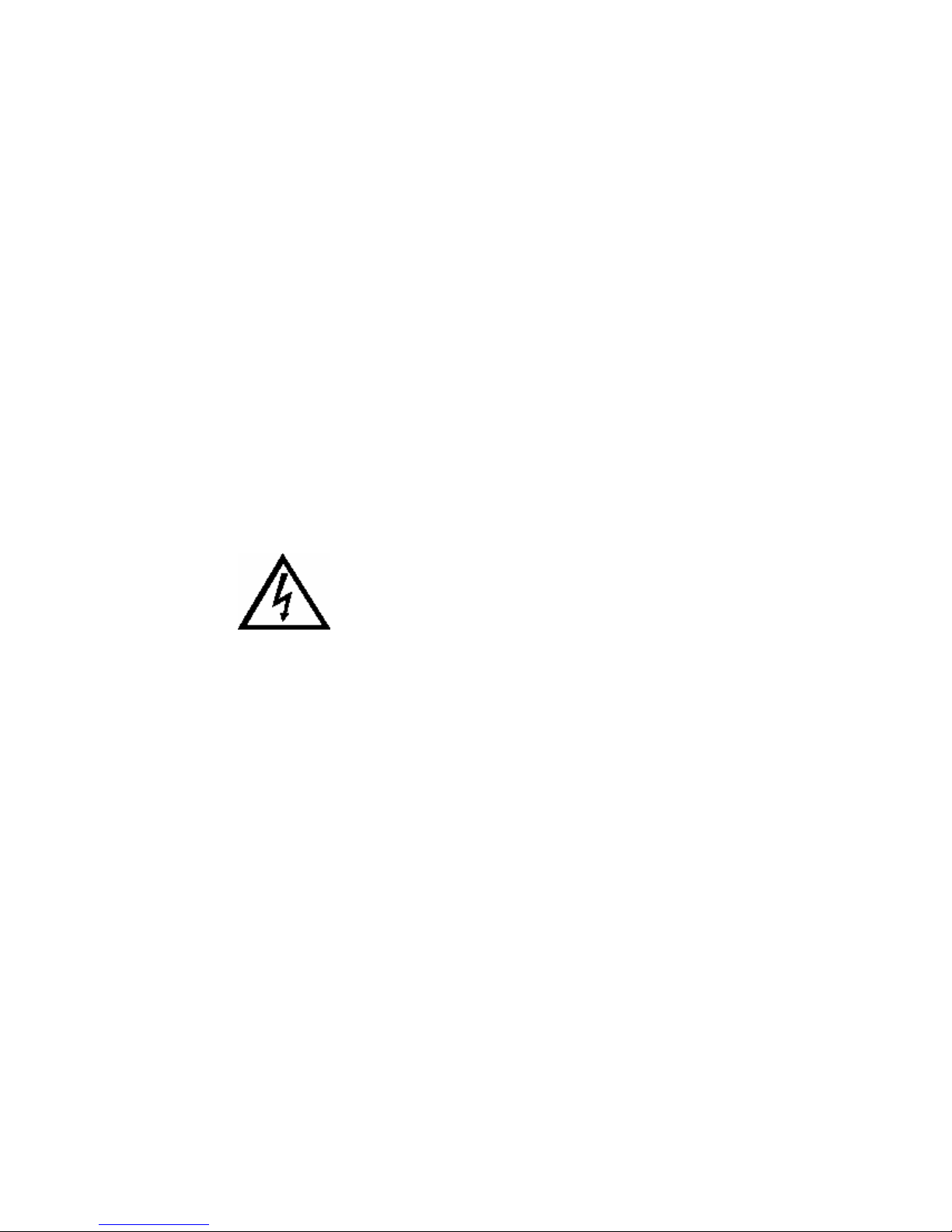
2.3.19. PA01 – Inclined bench ......................................................................................................................2.13
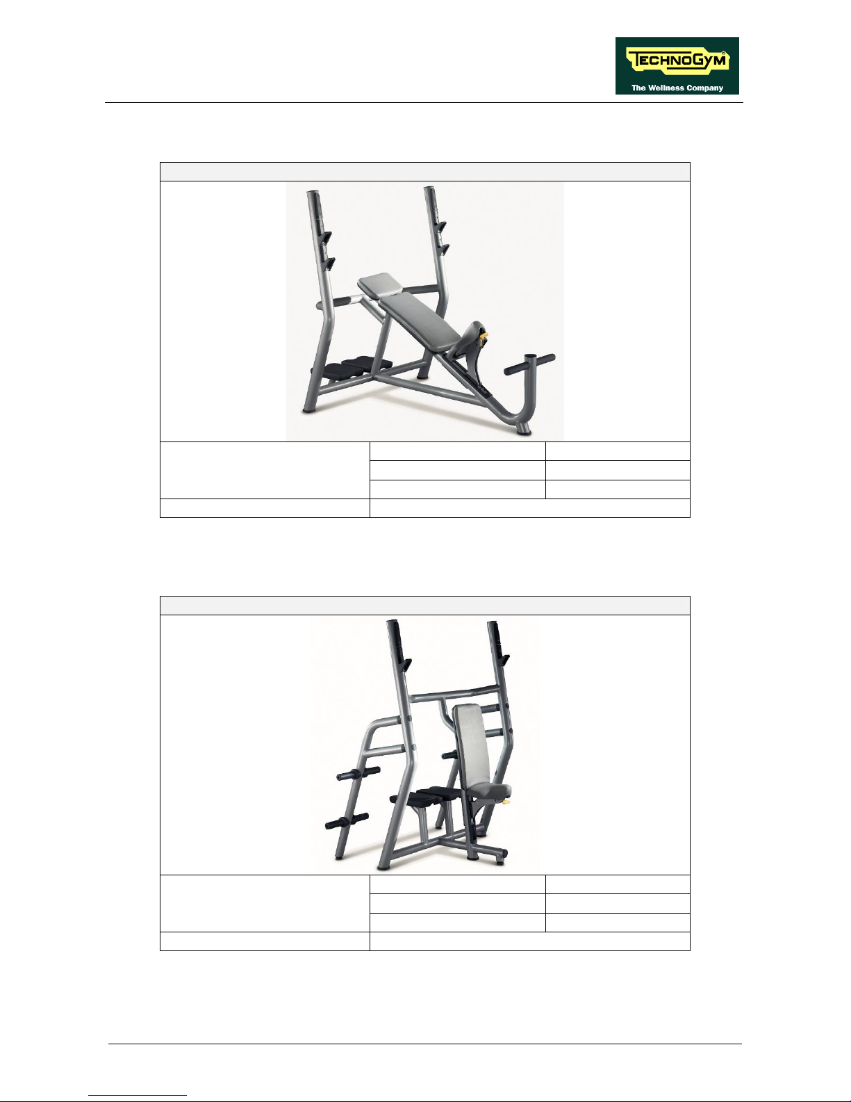
2.3.20. PA02 – Vertical bench.......................................................................................................................2.13
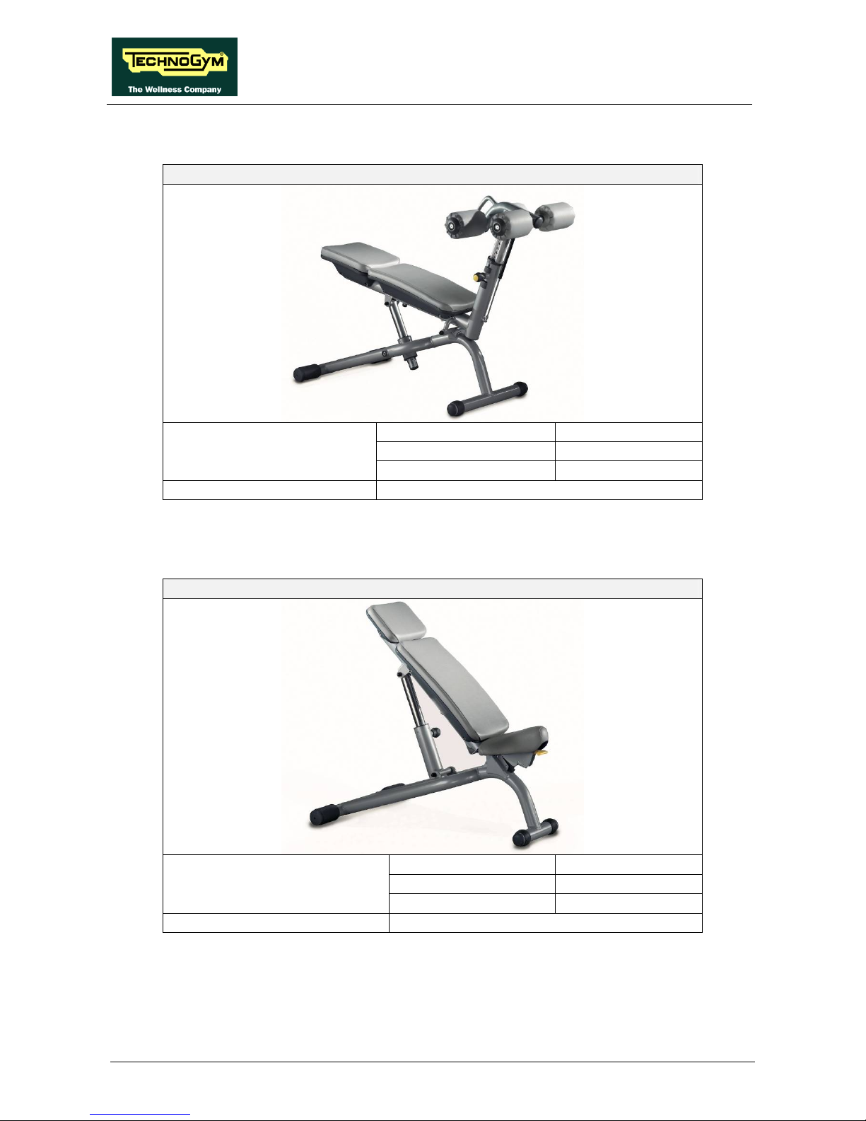
2.3.21. PA03 –Crunch bench.........................................................................................................................2.14
2.3.22. PA04 – Adjustable bench ..................................................................................................................2.14
2.3.23. PA05 –Lower Back bench .................................................................................................................2.15
2.3.24. PA06 –Scott bench.............................................................................................................................2.15
2.3.25. PA07 – Horizontal bench..................................................................................................................2.16
2.4. AMBIENT SPECIFICATIONS................................................................................................................................2.16
2.5. CONFORMITY TO REGULATIONS........................................................................................................................2.16
3. INSTALLING AND MOVING THE MACHINES.............................................................................................. 3.1
3.1. SPECIFICATIONS AND REQUIREMENTS ................................................................................................................3.1
3.2. INSTALLING AND MOVING THE MACHINES..........................................................................................................3.1
3.3. LIFTING AND MOVING.........................................................................................................................................3.2
3.4. INSTALLING THE MACHINE ALREADY ASSEMBLED..............................................................................................3.3
3.5. INSTALLING THE MACHINE TO BE ASSEMBLED.................................................................................................... 3.4
3.5.1. MA50 – Leg Press ...............................................................................................................................3.4
3.5.2. MA85 – Ercolina Crossover Cable .....................................................................................................3.5
3.5.3. PA02 – Vertical Bench ........................................................................................................................3.8
3.6. MACHINE SECURING.........................................................................................................................................3.10
3.6.1. Fixing a wall: Ercolina, Ercolina Rehab e Cross Cables................................................................. 3.10
3.6.2. Fixing the ceiling: Cavi Incrociati ....................................................................................................3.12
4. ACCESSORIES.......................................................................................................................................................4.1

ELEMENT LINE: Service & Maintenance Manual - rev. 1.2
Page ii
4.1. BARBELL HOLDER, PLATES HOLDER AND DUMBELL HOLDER..............................................................................4.1
4.1.1. A0000230: Barbell Rack.....................................................................................................................4.1
4.1.2. A0000231: Plate Rack........................................................................................................... .............. 4.2
4.1.3. A0000421: Urethane - Encased Dumbell Rack...................................................................................4.2
4.1.4. A0000364: Chrome Dumbbell Rack....................................................................................................4.3
4.2. WHAT TO ORDER TO AUGMENT THE WEIGHT STACK...........................................................................................4.4
5. HOW TO DISASSEMBLE THE ….......................................................................................................................5.1
5.1. WEIGHT STACK CASING...................................................................................................................................... 5.1
5.2. DISASSEMBLING THE WEIGHT STACK..................................................................................................................5.2
5.3. SEAT ON LOW MACHINES.................................................................................................................................... 5.3
5.4. SEAT ON TALL MACHINES...................................................................................................................................5.4
5.5. LEG PRESS SEAT.................................................................................................................................................5.6
5.6. RELEASE LEVER..................................................................................................................................................5.8
5.7. DISASSEMBLING UNLOCKING LEVER ON ABDUCTOR - ADDUCTOR...................................................................5.10
5.8. DISASSEMBLING SHOULDER REST LEVER ON ABDOMINAL CRUNCH.................................................................5.12
5.9. DISASSEMBLING ROLLERS ADJUSTING SYSTEM ON LAT MACHINE .................................................................... 5.13
5.10. DISASSEMBLING HANDLES ADJUSTING SYSTEM ON CHEST PRESS ..................................................................... 5.15
5.11. DISASSEMBLING EASY START SYSTEM ON PECTORAL.......................................................................................5.17
5.12. DISASSEMBLING THE ADDITIONAL WEIGHT ......................................................................................................5.18
6. WHAT IF ….............................................................................................................................................................6.1
6.1. THE WEIGHT STACK DOES NOT SLIDE SMOOTHLY ...............................................................................................6.1
6.2. THE WEIGHT STACK CABLE IS NOT TAUT.............................................................................................................6.2
6.3. THE MACHINE IS NOT FLAT.................................................................................................................................6.3
6.4. THE LEVERS OF DUAL-AXIS MACHINES ARE NOT ALIGNED..................................................................................6.4
7. SPECIAL OPERATIONS.......................................................................................................................................7.1
7.1. LOCKING DOWN THE CABLE FIXING DOWELS......................................................................................................7.1
7.2. LOCKING DOWN THE PULLEYS............................................................................................................................ 7.2
7.3. LOCKING DOWN THE DOWELS ON THE ARM EXTENSION LEVER..........................................................................7.3
8. WEIGHT STACK CABLE.....................................................................................................................................8.1
8.1. LENGTH OF THE WEIGHT STACK CABLES.............................................................................................................8.1
8.2. ROUTING OF THE WEIGHT STACK CABLE.............................................................................................................8.2
8.2.1. MA05 – Adductor ................................................................................................................................8.2
8.2.2. MA10 – Abductor ................................................................................................................................8.3
8.2.3. MA15 – Shoulder Press.......................................................................................................................8.3
8.2.4. MA20 – Chest Press ............................................................................................................................8.4
8.2.5. MA25 – Vertical Traction....................................................................................................................8.4
8.2.6. MA30 – Leg Extension ........................................................................................................................8.5
8.2.7. MA35 – Leg Curl.................................................................................................................................8.5
8.2.8. MA40 – Lat Machine...........................................................................................................................8.6
8.2.9. MA45 – Lower Back............................................................................................................................8.6
8.2.10. MA50 – Leg Press ...............................................................................................................................8.7
8.2.11. MA55 – Arm Curl................................................................................................................................8.7
8.2.12. MA60 – Arm Extension........................................................................................................................8.8
8.2.13. MA65 – Abdominal Crunch.................................................................................................................8.8
8.2.14. MA70 – Pectoral .................................................................................................................................8.9
8.2.15. MA75 – Glute ......................................................................................................................................8.9
8.2.16. MA80 – Ercolina............................................................................................................................... 8.10
8.2.17. MA85 – Ercolina Cross Over Cable .................................................................................................8.10
8.2.18. MA90 – Ercolina Rehab....................................................................................................................8.11
8.2.19. MA95 – Low Row.............................................................................................................................. 8.11
9. MAINTENANCE.....................................................................................................................................................9.1
9.1. DAILY MAINTENANCE OPERATIONS....................................................................................................................9.1
9.1.1. Cleaning upholstery ............................................................................................................................9.1
9.2. WEEKLY MAINTENANCE OPERATIONS ................................................................................................................ 9.2

ELEMENT LINE: Service & Maintenance Manual - rev. 1.2
Page iii
9.2.1. Cleaning the frame and painted parts.................................................................................................9.2
9.3. MONTHLY MAINTENANCE OPERATIONS.............................................................................................................. 9.3
9.3.1. Check the cross, bars and weight stack plates ....................................................................................9.3
9.3.2. Check the cables..................................................................................................................................9.3
9.3.3. Check the mechanisms.........................................................................................................................9.3
9.3.4. Check the gas springs.......................................................................................................................... 9.3
9.3.5. Check the weight stack stops...............................................................................................................9.4
9.3.6. Check the Leg Press seat mechanism..................................................................................................9.4
9.3.7. Checking the seat mechanism on low machines..................................................................................9.4
9.3.8. Checking the seat mechanism on tall machines ..................................................................................9.4
9.3.9. Checking the upholstery...................................................................................................................... 9.4
9.3.10. Checking various rubber parts............................................................................................................9.4
9.4. TWICE-YEARLY MAINTENANCE OPERATIONS......................................................................................................9.5
9.4.1. Check the pulleys.................................................................................................................................9.5
9.4.2. Check the cam group...........................................................................................................................9.5
9.4.3. Check the lever stops...........................................................................................................................9.5
9.4.4. Replacing the cables............................................................................................................................ 9.5
9.4.5. Lubricating the release systems...........................................................................................................9.5
9.4.6. Screw and bolt check...........................................................................................................................9.6
9.4.7. Checking for mechanism play .............................................................................................................9.6
9.4.8. Checking cross alignment....................................................................................................................9.6
10. APPENDIX.............................................................................................................................................................10.1
10.1. TOOLS TO USE ..................................................................................................................................................10.1

ELEMENT LINE: Service & Maintenance Manual - rev. 1.2
Page iv
Page intentionally left blank

ELEMENT LINE: Service & Maintenance Manual - rev. 1.2
Page 1.1
1. GENERAL NOTICES
1.1. INTRODUCTION
This document is reserved for Technogym Service technicians, and is intended to provide
authorized personnel with the necessary information to correctly carry out repairs and maintenance.
A thorough knowledge of the technical information contained in this manual is essential for
completing the professional training of the operator.
In order to facilitate consultation, the paragraphs are accompanied by schematic drawings which
illustrate the procedure being described.
This manual contains notices and symbols which have a specific meaning:
WARNING: non observance may result in accident or injury.
CAUTION: non observance may cause damage to the machine.
Information about the operation in progress.
observation about the operation in progress.
1.2. RECOMMENDATIONS
Technogym recommends the following steps for planning repair procedures:
• Carefully evaluate the customer’s description of the machine malfunction and ask all the
necessary questions to clarify the symptoms of the problem.
• Clearly diagnose the causes of the problem. This manual provides the fundamental theoretical
basis, which must then be integrated by personal experience and attendance at the training
courses periodically offered by Technogym.
• Rationally plan the repair procedure so as to minimize the downtime necessary for procuring
spare parts, preparing tools, etc.
• Access the component to be repaired, avoiding any unnecessary operations. In this regard it will
be useful to refer to the disassembly sequence described in this manual.

ELEMENT LINE: Service & Maintenance Manual - rev. 1.2
Page 1.2
1.3. GENERAL RULES FOR REPAIR PROCEDURES
1. Always mark any parts or positions which may be confused with each other at the time of
reassembly.
2. Use original Technogym spare parts and lubricants of the recommended brands.
3. Use special tools where specified.
4. Consult the Technical Newsletters, which may contain more up-to-date information on
adjustments and maintenance than those contained in this manual.
5. Before starting the repair procedure, make sure that the recommended tools are available and in
good condition.
6. For the procedures described in this manual, use only the specified tools.
The tool sizes quoted in this manual are expressed in mm.

ELEMENT LINE: Service & Maintenance Manual - rev. 1.2
Page 2.1
2. TECHNICAL CHARACTERISTICS
The Element machine code is a sequence of 14 alphanumeric characters arranged as follows:
ELEMENT LINE
Characters description key to values
1,2 Element Line
MA = Element machine
PA = Element benches
3,4 Machine code See paragraph: 2.1. “Colour options”
5 Weight stack configuration
N = None
0 = Standard
2 = enhanced +20 Kg (
1
)
3 = enhanced +30 Kg (
2
)
5 = enhanced +50 Kg (
3
)
6 Additional weight
N = None
C = 2.5 Kg additional weight
7 Isocontrol
0 = None
1 = Isocontrol
-
8,9 Frame colour
AL = silver
10,11 Upholstery colour
AN = silver
V0 = black
K0 = aviation blue
M0 = Bordeaux (benches only)
12,13 Rubber colour
GG = grey RAL 7024
14 Casing colour
A = white
G = grey
J = I-Pac
15 Unit of measurement
K = Kg
L = pound
NOTES:
(
1
) Valid on Abdominal Crunch, Abductor, Adductor, Arm Curl, Arm Extension, Leg Extension,
Leg Curl, Lower Back, Shoulder Press and Vertical Traction.
(
2
) Valid on Chest Press, Lat Machine, Low Row and Pectoral.
(
3
) Valid on Ercolina, Ercolina Rehab and Cross Over Cables.

ELEMENT LINE: Service & Maintenance Manual - rev. 1.2
Page 2.2
For example, a possible product code would be:
MA150N0-ALANGGAK
which is interpreted as follows:
MA 15 0 N 0 - ALANGG A K
Unit of measurement, Kg
Casing colour, white
Rubber colour, grey RAL 7024
Upholstery colour, silver
Frame colour, aluminium
NO, Isocontrol
NO, additional weight
Weight stack configuration, standard
Shoulder Press
Element Line machine
2.1. COLOUR OPTIONS
The following table shows the possible combinations for ordering the Classic Selection line
machines:
CONFIGURATION -1- CONFIGURATION -2- CONFIGURAZIONE -3-
FRAME AL - SILVER AL - SILVER AL - SILVER
CASING A - WHITE G –GREY J – I PAC
UPHOLSTERY AN - SILVER V0 - BLACK K0 - BLUE
Table 2-1

ELEMENT LINE: Service & Maintenance Manual - rev. 1.2
Page 2.3
2.2. PRODUCT CODING
2.2.1. MACHINES CODES
Code Machine
05 Adductor
10 Abductor
15 Shoulder Press
20 Chest Press
25 Vertical traction
30 Leg Extension
35 Leg Curl
40 Lat Machine
45 Lower Back
50 Leg Press
55 Arm Curl
60 Arm Extension
65 Abdominal Crunch
70 Pectoral Machine
75 Glute
80 Ercolina
83 Multipower
85 Crossover Cable
90 Ercolina Rehab
95 Low Row
2.2.2. BENCHES CODES
Code Machine
01 Inclined bench
02 Vertical bench
03 Crunch bench
04 Adjustable bench
05 Lower Back bench
06 Scott bench
07 Horizontal bench

ELEMENT LINE: Service & Maintenance Manual - rev. 1.2
Page 2.4
2.3. EQUIPMENTS: MECHANICAL CHARACTERISTICS
2.3.1. MA05 – ADDUCTOR
MA05 - Adductor
stand by max during exercise
141 x 82 x 142 cm
Dimensions
55.5 x 32.3 x 55.9 in
Overall weight 140 Kg – 280 lbs
Standard weight stack 60 Kg – 120 lbs
Enhanced weight stack 80 Kg – 160 lbs
2.3.2. MA10 – ABDUCTOR
MA10 – Abductor
stand by max during exercise
141 x 82 x 142 cm
Dimensions
55.5 x 32.3 x 55.9 in
Overall weight 140 Kg – 280 lbs
Standard weight stack 60 Kg – 120 lbs
Enhanced weight stack 80 Kg – 160 lbs

ELEMENT LINE: Service & Maintenance Manual - rev. 1.2
Page 2.5
2.3.3. MA15 – SHOULDER PRESS
M8A15 – Shoulder Press
stand by max during exercise
144 x 87 x 142 cm
Dimensions
56.7 x 34.3 x 55.9 in
Overall weight 170 Kg – 340 lbs
Standard weight stack 60 Kg – 120 lbs
Enhanced weight stack 80 Kg – 160 lbs
2.3.4. MA20 – CHEST PRESS
MA20 – Chest Press
stand by max during exercise
139 x 83 x 162 cm
Dimensions
54.7 x 32.7 x 63.8 in
Overall weight 190 Kg – 380 lbs
Standard weight stack 90 Kg – 180 lbs
Enhanced weight stack 120 Kg – 240 lbs

ELEMENT LINE: Service & Maintenance Manual - rev. 1.2
Page 2.6
2.3.5. MA30 – LEG EXTENSION
MA30 – Leg Extension
stand by max during exercise
127 x 104 x 142 cm
Dimensions
50 x 41 x 56.9 in
Overall weight 200 Kg – 400 lbs
Standard weight stack 80 Kg – 160 lbs
Enhanced weight stack 100 Kg – 200 lbs
2.3.6. MA35 – LEG CURL
MA35 – Leg Curl
stand by max during exercise
127 x 104 x 142 cm
Dimensions
50 x 41 x 56.9 in
Overall weight 200 Kg – 400 lbs
Standard weight stack 80 Kg – 160 lbs
Enhanced weight stack 100 Kg – 200 lbs

ELEMENT LINE: Service & Maintenance Manual - rev. 1.2
Page 2.7
2.3.7. MA40 – LAT MACHINE
MA40 – Lat Machine
stand by max during exercise
120 x 120 x 223 cm
Dimensions
47.8 x 47.8 x 88 in
Overall weight 270 Kg – 540 lbs
Standard weight stack 90 Kg – 180 lbs
Enhanced weight stack 120 Kg – 240 lbs
2.3.8. MA45 – LOWER BACK
MA45 – Lower Back
stand by max during exercise
120 x 95 x 142 cm
Dimensions
47.8 x 37.4 x 55.9 in
Overall weight 200 Kg – 400 lbs
Standard weight stack 70 Kg – 140 lbs
Enhanced weight stack 90 Kg – 180 lbs

ELEMENT LINE: Service & Maintenance Manual - rev. 1.2
Page 2.8
2.3.9. MA50 – LEG PRESS
MA50 – Leg Press
stand by max during exercise
210 x 115 x 152 cm
Dimensions
82.7 x 45.3 x 59.9 in
Overall weight 570 Kg – 1140 lbs
Standard weight stack 200 Kg – 400 lbs
Enhanced weight stack -
2.3.10. MA55 – ARM CURL
MA55 – Arm Curl
stand by max during exercise
139 x 80 x 142 cm
Dimensions
54.7 x 31.5 x 55.9 in
Overall weight 155 Kg – 310 lbs
Standard weight stack 60 Kg – 120 lbs
Enhanced weight stack 80 Kg – 160 lbs

ELEMENT LINE: Service & Maintenance Manual - rev. 1.2
Page 2.9
2.3.11. MA60 – ARM EXTENSION
MA60 – Arm Extension
stand by max during exercise
141 x 80 x 142 cm
Dimensions
55.5 x 31.5 x 55.9 in
Overall weight 170 Kg – 340 lbs
Standard weight stack 70 Kg – 140 lbs
Enhanced weight stack 90 Kg – 180 lbs
2.3.12. MA65 – ABDOMINAL CRUNCH
MA65 – Abdominal Crunch
stand by max during exercise
133 x 89 x 142 cm
Dimensions
52.4 x 35 x 55.9 in
Overall weight 180 Kg – 360 lbs
Standard weight stack 60 Kg – 120 lbs
Enhanced weight stack 80 Kg – 160 lbs

ELEMENT LINE: Service & Maintenance Manual - rev. 1.2
Page 2.10
2.3.13. MA70 – PECTORAL
MA70 – Pectoral
stand by max during exercise
149 x 82 x 142 cm
Dimensions
59 x 32 x 56 in
Overall weight 190 Kg – 380 lbs
Standard weight stack 90 Kg – 180 lbs
Enhanced weight stack 120 Kg – 240 lbs
2.3.14. MA75 – GLUTE
MA75 – Glute
stand by max during exercise
114 x 132 x 142 cm
Dimensions
45 x 52 x 56 in
Overall weight 225 Kg – 450 lbs
Standard weight stack 60 Kg – 120 lbs
Enhanced weight stack –

ELEMENT LINE: Service & Maintenance Manual - rev. 1.2
Page 2.11
2.3.15. MA80 – ERCOLINA
MA80– Ercolina
stand by max during exercise
66 x 69 x 242 cm
Dimensions
26 x 27.2 x 95.3 in
Overall weight 130 Kg – 260 lbs
Standard weight stack 27,5 Kg – 55 lbs
Enhanced weight stack 50 Kg – 100 lbs
2.3.16. MA85 – ERCOLINA CROSSOVER CABLE
MA85 – Ercolina Crossover Cable
stand by max during exercise
66 x 324 x 231 cm
Dimensions
26 x 127.6 x 91 in
Overall weight 280 Kg – 560 lbs
Standard weight stack 27,5x2 Kg – 55x2 lbs
Enhanced weight stack 50x2 Kg – 100x2 lbs

ELEMENT LINE: Service & Maintenance Manual - rev. 1.2
Page 2.12
2.3.17. MA90 – ERCOLINA REHAB
MA90– Ercolina Rehab
stand by max during exercise
66 x 69 x 242 cm
Dimensions
26 x 27.2 x 95.3 in
Overall weight 130 Kg – 260 lbs
Standard weight stack 27,5 Kg – 55 lbs
Enhanced weight stack 50 Kg – 100 lbs
2.3.18. MA95 – LOW ROW
MA95 – Low Row
stand by max during exercise
124 x 82 x 142 cm
Dimensions
49 x 32 x 56 in
Overall weight 170 Kg – 340 lbs
Standard weight stack 90 Kg – 180 lbs
Enhanced weight stack 120 Kg – 240 lbs
ELEMENT LINE: Service & Maintenance Manual - rev. 1.2
Page 2.13
2.3.19. PA01 – INCLINED BENCH
PA01– Inclined bench
stand by max during exercise
189.6 x 126.7 x 152.8 cm
Dimensions
75 x 50 x 60 in
Overall weight 71 Kg – 142 lbs
2.3.20. PA02 – VERTICAL BENCH
PA02 –Vertical bench
stand by max during exercise
119.7 x 160.6 x 177.6 cm
Dimensions
47 x 63 x 70 in
Overall weight 71 Kg – 142 lbs
ELEMENT LINE: Service & Maintenance Manual - rev. 1.2
Page 2.14
2.3.21. PA03 –CRUNCH BENCH
PA03–Crunch bench
stand by max during exercise
143.6 x 69.7 x 110.8 cm
Dimensions
57 x 27 x 44 in
Overall weight 75 Kg – 150 lbs
2.3.22. PA04 – ADJUSTABLE BENCH
PA04 – Adjustable bench
stand by max during exercise
119.8 x 69.7 x 131.2 cm
Dimensions
47 x 27 x 52 in
Overall weight 59 Kg – 118 lbs

ELEMENT LINE: Service & Maintenance Manual - rev. 1.2
Page 2.15
2.3.23. PA05 –LOWER BACK BENCH
PA05–Lower Back bench
stand by max during exercise
106.9 x 757 x 769 cm
Dimensions
42 x 30 x 30 in
Overall weight 36 Kg – 72 lbs
2.3.24. PA06 –SCOTT BENCH
PA06 –Scott bench
stand by max during exercise
101.1 x 780 x 998 cm
Dimensions
40 x 31 x 39 in
Overall weight 36 Kg – 72 lbs

ELEMENT LINE: Service & Maintenance Manual - rev. 1.2
Page 2.16
2.3.25. PA07 – HORIZONTAL BENCH
PA07 – Horizontal bench
stand by max during exercise
172.5 x 160.6 x 130.2 cm
Dimensions
68 x 63 x 39 in
Overall weight 59 Kg – 118 lbs
Be aware:
• The weights in the above tables refer to machines with standard weight stack.
• The dimensions are “length x width x height” related to the user in exercise position.
• The stand by dimensions are the minimum machine dimensions without any
disassembling.
2.4. AMBIENT SPECIFICATIONS
Operating from 5° to 35° C
Temperature
Storage from -20 to 55° C
Operating from 30% to 80% non-condensing
Humidity
Storage from 5% to 85% non-condensing
2.5. CONFORMITY TO REGULATIONS
The machine conforms to the following directives:
Directive Europe USA
Machinery directive
98/37/CEE
Mechanical safety
EN 957-1
EN 957-2
EN 957-4
EN 957-1
EN 957-2
EN 957-4

ELEMENT LINE: Service & Maintenance Manual - rev. 1.2
Page 3.1
3. INSTALLING AND MOVING THE
MACHINES
3.1. SPECIFICATIONS AND REQUIREMENTS
For proper installation of the equipment, make sure that:
1. The equipment is installed on a level, vibration-free surface with a sufficient capacity to support
its weight plus that of the user.
2. The area is not dusty or sandy.
3. You have observed the temperature and humidity operating requirements indicated in
paragraph 2.4. “Ambient specifications”.
3.2. INSTALLING AND MOVING THE MACHINES
The equipment is supplied on a pallet, to which it is secured by means of straps. To remove the
equipment from the packing:
1. Cut the carton along the bottom and pull it away from the top;
2. Remove the cellophane by pulling it away from the top;
3. Untie the straps securing the equipment to the pallet;
4. Lift the equipment from the weight stack side and place it on the ground;
5. Remove the spacer from between the two panels of the weight stack.
Do not throw the spacer (A) away as it must be used (putting it in the same position) in
case of any further moving of the machine.

ELEMENT LINE: Service & Maintenance Manual - rev. 1.2
Page 3.2
3.3. LIFTING AND MOVING
In case of raising or moving the machine, do not press against casings or other
breakable parts, but only against the frame.
To move the machine, preferably use a tipping trolley, lifting it from the weight stack end using the
wooden insert fitted on the machine for transport
Figure 3.3-1
• If you use different means of transportation as pallet changer or lift truck, adequately protect
the parts of the frame that will be in contact with it.
• Insert the means of transportation (pallet changer or lift truck from the weight stack side.
• Move the machine carefully, making sure it does not overbalance.
Once the machine is in the desired place of installation, level it by adjusting the height of
one or more of the machine feet as described in paragraph 6.3. “The machine is not
flat”.

ELEMENT LINE: Service & Maintenance Manual - rev. 1.2
Page 3.3
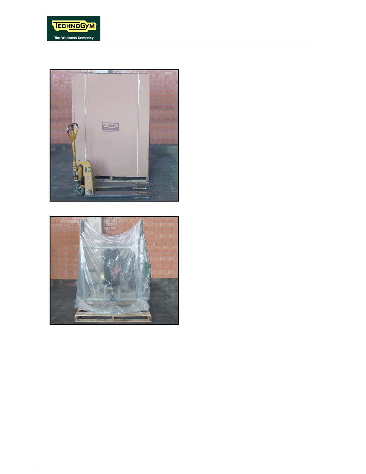
3.4. INSTALLING THE MACHINE ALREADY ASSEMBLED
Figure 3.4-1
1. The machine is supplied on a wooden pallet,
wrapped in nylon bag and packed in a carton.
2. To move the machine, it is necessary to use a
pallet truck or fork lift truck.
Figure 3.4-2
3. Remove the carton, the nylon bag and the
fixing straps which secure the machine on
the pallet.
4. Use a trolley to position the machine in the
place of installation, lifting it from the
weight stack end as shown by the arrows in
the figure, and leaving the wooden slat in
place.

ELEMENT LINE: Service & Maintenance Manual - rev. 1.2
Page 3.4
3.5. INSTALLING THE MACHINE TO BE ASSEMBLED
3.5.1. MA50 – LEG PRESS
Figure 3.5-1
1. The Leg Press is delivered on a wooden
pallet, wrapped in nylon bag and packed in a
carton.
2. To move the machine, it is necessary to use a
pallet truck or fork lift truck
Figure 3.5-2
3. Remove the carton and the nylon bag.
4. The machine is delivered with the rear guard
disassembled, and is fitted with the wooden
spacer (a) to protect it during handling with a
trolley as shown in the figure.
5. The support (b) at the base of the weight
stack prevents the base of the truck from
damaging the frame.
6. Remove the spacer (a) and mount the rear
casing on the machine.

ELEMENT LINE: Service & Maintenance Manual - rev. 1.2
Page 3.5
3.5.2. MA85 – ERCOLINA CROSSOVER CABLE
Figure 3.5-3
1. The Crossover Cable is delivered on a
wooden pallet, wrapped in nylon bag and
packed in a carton.
2. To move the machine, it is necessary to use a
pallet truck or fork lift truck
Figure 3.5-4
3. Remove the carton and the nylon bag and
arrange the various components needed to
assemble the machine on the floor:
• The two columns with the weight stack
(Ercolina) (a);
• The crossbar (b),
• The box which contains all the fixing
screws and some accessories.
Continued on the following page
→

ELEMENT LINE: Service & Maintenance Manual - rev. 1.2
Page 3.6
Figure 3.5-5
4. In particular, the carton box contains:
• The set of screws and hooks (1) to fix the
machine on the floor or on the wall;
• The set of screws (2) used to fix the
crossbar;
• The cable end pieces (3) and (4) with
some extra grub screws;
• Four cable ducts (5) for frame’s holes;
• Four snap links (6) to use with
accessories;
• A set of accessories (7) for the machine
usage.
Figure 3.5-6
5. Insert the crossbar on the post at the top of
the weight stack column, and fix it using the
screws (3) shown in Figure 3.5-5, locking
down 3 of them
in the position s shown in the
picture to side.
Carry out this operation on both the Ercolina
modules.
Figure 3.5-7
6. Insert two of the cable duct (5), of Figure
3.5-5, on the frame’s holes (d) shown in the
picture to side.
Carry out this operation on both the Ercolina
modules.
Continued on the following page
→

ELEMENT LINE: Service & Maintenance Manual - rev. 1.2
Page 3.7
Figure 3.5-8
7. Remove the cable from the hole on the
frame, pulling it out toward the inside, and
pass it through the pulley as indicated in the
figure to side.
8. After passing the cable on the pulley, insert a
rubber protection (5) on it.
9. Assemble one of the end piece (4) on the
cable as shown in the figure and lock down
the grub screws (e) using a 4-mm Allen
wrench.
10. Hide the end piece (4) with the rubber
protection.
Carry out this operation on both the Ercolina
modules.
WARNING: is necessary, at the end of the installation, set the machine on the wall or
ceiling.
ELEMENT LINE: Service & Maintenance Manual - rev. 1.2
Page 3.8
3.5.3. PA02 – VERTICAL BENCH
Figure 3.5-9
1. The Vertical Bench is delivered on a wooden
pallet, wrapped in nylon bag and packed in a
carton.
2. To move the machine, it is necessary to use a
pallet truck or fork lift truck
Figure 3.5-10
3. Remove the carton and the nylon bag and
arrange the various components on the floor:
• the bench;
• a cartoon box.
Continued on the following page
→

ELEMENT LINE: Service & Maintenance Manual - rev. 1.2
Page 3.9
Figure 3.5-11
4. In particular, the carton box contains:
• the four plates holders (a);
• the four covering pieces (b);
• the four stud bolt pin (c).
Figure 3.5-12
5. Screw the stud bolt pin c in the plates holder
(a).
Figure 3.5-13
6. Insert one of the covering piece (b) on the
post in the external side of the frame.
Figure 3.5-14
7. Screw the plates holder on the frame.
Carry out the previous operations for all the four
plates holders supplied with the machine.

ELEMENT LINE: Service & Maintenance Manual - rev. 1.2
Page 3.10
3.6. MACHINE SECURING
WARNING: it is necessary that some machines detailed below, are fixed to the wall or
ceiling, for their particular shape and / or how to use.
3.6.1. FIXING A WALL: ERCOLINA, ERCOLINA REHAB E CROSS CABLES
1. Insert the screws (a) in frame holes (b) as indicated in the figure,
2. insert brackets (c) and washers (d) in the protruding screw section,
The brackets may be rotated around the fastening axis to facilitate sub sequent wall-
fastening and then repositioned correctly.
3. tighten the brackets slightly using selflocking nuts (e) to hold them in position,
Figure 3.6-1

ELEMENT LINE: Service & Maintenance Manual - rev. 1.2
Page 3.11
4. mark the position of two Ø 14 holes on the wall,
5. fully tighten brackets (c) to the frame,
6. drill the wall and insert rawl plugs (f) in the wall holes,
7. bring the equipment up to the wall and ensure the holes in the wall are aligned with the holes on
the bracket,
8. screw in screws (g) and tighten to the wall.
Figure 3.6-2
WARNING: is obligatory to secure the equipment to the wall using the appropriate
screw and brackets.

ELEMENT LINE: Service & Maintenance Manual - rev. 1.2
Page 3.12
3.6.2. FIXING THE CEILING: CAVI INCROCIATI
Use cables, ropes or chains that strictly meet the following minimum requirement: minimum
guaranteed workload of 90 Kg.
Figure 3.6-3
1. Tighten the eyebolts (a) into the threaded holes(b),
Figure 3.6-4

ELEMENT LINE: Service & Maintenance Manual - rev. 1.2
Page 3.13
2. drill two holes in the ceiling or wall for the hooks (c) and insert the real plugs (d) into the holes,
3. screw in the hooks (c) into the rawl plugs(d) and tighten,
4. connect the hooks (c) to the eyebolts(a) using cables, ropes or chain (e).
The cables, ropes and chain are not supplied with the equipment.
The cables, ropes and chain must be under slight tension.

ELEMENT LINE: Service & Maintenance Manual - rev. 1.2
Page 3.14
Page intentionally left blank

ELEMENT LINE: Service & Maintenance Manual - rev. 1.2
Page 4.1
4. ACCESSORIES
4.1. BARBELL HOLDER, PLATES HOLDER AND DUMBELL
HOLDER
The Element + line barbell support and weight storage plate posts are available as accessories. The
order codes for these accessories are:
4.1.1. A0000230: BARBELL RACK
The code above should be complemented with colour variation:
CODE
-ALGG
-ANGG

ELEMENT LINE: Service & Maintenance Manual - rev. 1.2
Page 4.2
4.1.2. A0000231: PLATE RACK
The code above should be complemented with colour variation:
CODE
-ALGG
-ANGG
4.1.3. A0000421: URETHANE - ENCASED DUMBELL RACK
The code above should be complemented with colour variation:
CODE
-ALGG
-ANGG

ELEMENT LINE: Service & Maintenance Manual - rev. 1.2
Page 4.3
4.1.4. A0000364: CHROME DUMBBELL RACK
The code above should be complemented with colour variation:
CODE
-ALGG
-ANGG

ELEMENT LINE: Service & Maintenance Manual - rev. 1.2
Page 4.4
4.2. WHAT TO ORDER TO AUGMENT THE WEIGHT STACK
Weight stack
Cod. Machine
Standard Powere
d
Parts to power the
weight stack
Assembly
code
MA65 – Abdominal
Crunch
MA10 – Abductor
MA05 – Adductor
MA55 – Arm Curl
MA15 – Shoulder Press
60 kg
120 lbs
80 kg
160 lbs
0F137AA-GG x 4 (weight)
0B178AA
(2)
x 8 (bushing)
0E000018-(KG/LB) x 1 (sticker)
0P000653AA X 1 (selector rod)
R0003980AA-KG
R0003980AA-LB
MA60 – Arm Extension
MA45 – Lower Back
70 kg
140 lbs
90 kg
180 lbs
0F137AA-GG x 4 (weight)
0B178AA
(2)
x 8 (bushing)
0E000018-(KG/LB) x 1 (sticker)
0P000697AA x 1 (selector rod)
R0003981AA-KG
R0003981AA-LB
MA35 – Leg Curl
MA30 – Leg Extension
80 kg
160 lbs
100 kg
200 lbs
0F137AA-GG x 4 (weight)
0B178AA
(2)
x 8 (bushing)
0E000018-(KG/LB) x 1 (sticker)
0P000697AA x 1 (selector rod)
R0003981AA-KG
R0003981AA-LB
MA20 – Chest Press
MA40 – Lat Machine
MA95 – Low Row
MA70 – Pectoral Machines
90 kg
180 lbs
120 kg
240 lbs
0F137AA-GG x 6 (weight)
0B178AA
(2)
x 12 (bushing)
0E000018-(KG/LB) x 1 (sticker)
0P000732AA x 1 (selector rod)
R0003982AA-KG
R0003982AA-LB
MA85 – Crossover cable
(1)
MA80 – Ercolina
MA90 – Ercolina Rehab
25 kg
50 lbs
50 kg
100 lbs
0F137AA-GG x 10 (weight)
0B178AA
(2)
x 20 (bushing)
0E000145-(KG/LB) x 1 (sticker)
0P000745AA x 1 (selector rod)
R0003983AA-KG
R0003983AA-LB
MA25 – Vertical Traction
90 kg
18 lbs
110 kg
220 lbs
0F137AA-GG x 4 (weight)
0B178AA
(2)
x 8 (bushing)
0E000018-(KG/LB) x 1 (sticker)
0P000732AA x 1 (selector rod)
R0003984AA-KG
R0003984AA-LB
CAUTION:
(1)
For the Cable Cross, the elements specified in the upgrade table must be included for each of
the two Ercolina modules which make up the machine.
(2)
Bushings of different thickness are available for more precise adjustment of the weight stack
plates, so that they can all be easily selected using the pin.
CODE THICKNESS (mm)
0B178AA 2.5
0B000563AA 2
0B000562AA 1.5
ELEMENT LINE: Service & Maintenance Manual - rev. 1.2
Page 5.1
5. HOW TO DISASSEMBLE THE …
5.1. WEIGHT STACK CASING
Figure 5.1-1
1. Back off the screws (a), using a 4-mm hex
wrench.
2. Remove the front weight stack casing.
Figure 5.1-2
3. Before reassembling the casing, check all the
plastic bushing (b), with threaded piece, are
correctly inserted inside the support (c).
To disassemble the rear casing, carrying out the
procedure here above, on the rear side of the
machine.
To reassemble the weight stack casing, carry out
the above steps in reverse order.

ELEMENT LINE: Service & Maintenance Manual - rev. 1.2
Page 5.2
5.2. DISASSEMBLING THE WEIGHT STACK
Figure 5.2-1
Carry out the procedure described in paragraph
5.1. “Weight stack casing”.
1. Back off the screws (a), using a 5-mm hex
wrench.
2. Remove the weight stack casing support.
Figure 5.2-2
3. For both the weight stack rods, back off the
grub screws which secure the rods, reaching
them by the two holes (c) in the shock
absorbers. Use a 4-mm hex wrench.
The rod will move down by a few
centimetres.
Figure 5.2-3
4. Use a 4-mm hex wrench to back off the grub
screws (d) and remove the stop from both the
rods.
Figure 5.2-4
5. Back off the counter nut (e) and then the
threaded pin (f), using a 22-mm wrench.
6. Push the rods toward the back in order to
remove, from the top, all the plate of the
weight stack, additional weight assembly if
present.
To reassemble the weight stack, carry out the
above steps in reverse order.
After complete this procedure, adjust
the cable tension as detailed in
paragraph 6.2. “The weight stack cable
is not taut”.

ELEMENT LINE: Service & Maintenance Manual - rev. 1.2
Page 5.3
5.3. SEAT ON LOW MACHINES
This operation applies to Leg Curl and Leg Extension.
Figure 5.3-1
1. Back off the grub screws (a) which are fixing
the position of the seat position system lever,
using a 3-mm hex wrench. Carry out the
operation on both side of the seat.
Figure 5.3-2
2. Release the spring (b) of the seat position
system.
3. Slide the two plastic bushings (c) toward the
external side of the seat.
4. Remove the lever, sliding it out from the
lower side of the seat frame.
Figure 5.3-3
5. Move the seat into position 1 (all the way
forward) so that the gas spring is as fully
extended as possible.
6. Back off the screw (d) using a 5-mm hex
wrench.
7. Back off the screw (e) using a 6-mm hex
wrench and remove the plastic stop. Carry
out the operation on both side of the
machine.
8. Remove the seat, sliding it out from behind.
During the reassembling procedure
remember to place the spacer in the
inner side of the stop, as shown in the
picture.
To reassemble the weight stack, carry out the
above steps in reverse order.

ELEMENT LINE: Service & Maintenance Manual - rev. 1.2
Page 5.4
5.4. SEAT ON TALL MACHINES
This operation applies to Arm Curl, Arm Extension, Chest Press, Low Row, Pectoral,
Shoulder Press and Vertical Traction.
Figure 5.4-1
1. Remove the two rivets (a) and rotate the
plastic casing with the seat position numbers,
of 90° on the seat support.
Figure 5.4-2
2. Back off the screw (b) using a 5-gauge
hexagonal T-wrench.
3. Remove both the screw and the spacer which
are fixing the gas spring.
4. Remove the plastic cap (c).
Figure 5.4-3
5. Use an object such as a hammer handle to
compress the gas piston, then hold the piston
rod in place by inserting a screwdriver into
the hole underneath cap (c) and then into
hole underneath the spring as shown in the
figure.
6. Remove now the seat assembly from the
guides, pushing it toward the lower side.
Continued on next page
→

ELEMENT LINE: Service & Maintenance Manual - rev. 1.2
Page 5.5
Figure 5.4-4
To reassemble the seat assembly, carry out the
above steps in reverse order, compressing the
gas spring inside the tube as shown in the
picture to side.

ELEMENT LINE: Service & Maintenance Manual - rev. 1.2
Page 5.6
5.5. LEG PRESS SEAT
Figure 5.5-1
1. Remove the platform (a) using a 6-mm hex
wrench to back off the screws (b) (2 on each
side) indicated by the arrows in the figure,
which are accessed from the bottom.
Before continuing, use a strap to secure
the seat in the all-back position on the
guide bars, to prevent the cam (c) from
covering the screws (b).
Figure 5.5-2
2. Back off the screws (e) using a 3-mm hex
wrench.
3. Move the seat to the all-back position on the
guide bars.
4. Remove the cover plate (d) by pulling it
toward the front.
During reassembly, fit the spacers (f) on
the screws securing the cover plate.
Figure 5.5-3
5. Loosen the 4 dowels (g), using a 4-gauge
hexagonal T-wrench.
6. Remove the cable.
Continued on next page
→

ELEMENT LINE: Service & Maintenance Manual - rev. 1.2
Page 5.7
Figure 5.5-4
On both side of the machine:
1. Remove the cap (h).
2. Back off the screw (i) using a 3-mm hex
wrench.
3. Remove the plastic guard (l).
Figure 5.5-5
7. Back off the screw (m) using a 6-mm hex
wrench.
8. Remove the eccentric pin (n) by pulling it on
the side.
During reassembly, adjust the position
of the cam so that the wheel is in contact
with the bar, and clamp it by locking
down screw (m).
Figure 5.5-6
9. Remove the wheel (o) from the pin (p).
10. Back off the pin (p) using a 12-mm hex
wrench.
11. Remove the seat assembly by pulling it
upward.
To reassemble the seat assembly, carry out the
above steps in reverse order.

ELEMENT LINE: Service & Maintenance Manual - rev. 1.2
Page 5.8
5.6. RELEASE LEVER
This operation applies to Leg Curl, Leg Extension Lower Back, and Glute.
Figure 5.6-1
1. Remove the plastic cap (a) using a flat
screwdriver.
Figure 5.6-2
2. Use a 10-mm wrench to back off the 3
screws (b).
3. Remove the plastic cover (c).
Figure 5.6-3
4. Back off the screw (d) using a 13-mm
wrench.
5. Remove the plate (e).
6. Back off the 4 screws (f) using a 4-mm hex
wrench.
7. Remove the tube (g) sliding it upward.
8. Slide the lever (h) a couple of cm toward the
external side, following the direction of the
arrow.
Continued on next page
→

ELEMENT LINE: Service & Maintenance Manual - rev. 1.2
Page 5.9
Figure 5.6-4
9. Remove the complete release button i and the
spring (l), sliding them upward.
Figure 5.6-5
10. Remove the spiral pin (m) and separate the
metal part of the release button from the
plastic one (n).
To reassemble the release button, carry out the
above steps in reverse order.

ELEMENT LINE: Service & Maintenance Manual - rev. 1.2
Page 5.10
5.7. DISASSEMBLING UNLOCKING LEVER ON ABDUCTOR -
ADDUCTOR
Figure 5.7-1
1. Remove the plastic cap (a).
2. Back off the screw (b) using an 8-mm hex
wrench, locking down the nut on the other
side with a 17-mm wrench.
Figure 5.7-2
3. Remove the two seeger (c) using the proper
pliers.
4. Remove the unlocking lever (d).
Figure 5.7-3
To disassemble the selector pin:
1. Back off the screws (e) using an 8-mm
wrench, locking down the pin with a pliers.
When reassemble the group, be careful
to insert all the bushings and the
washers in the same order, as shown in
the picture to side.
Continued on next page
→
ELEMENT LINE: Service & Maintenance Manual - rev. 1.2
Page 5.11
Figure 5.7-4
2. Back off the screw (f), using a 8-mm hex
wrench.
3. Remove the plastic stop (g).
Figure 5.7-5
4. Release the tension on the weight stack cable
by clamping the first plate as shown in the
figure.
Figure 5.7-6
5. Lift the selector pin using a pair of pliers and
turn the cam toward the back of the machine,
disengaging the cable from it.
6. Remove the pin (h) and its spring, pulling it
out from the bottom of the machine.
To reassemble the unlocking lever, carry out the
above steps in reverse order.

ELEMENT LINE: Service & Maintenance Manual - rev. 1.2
Page 5.12
5.8. DISASSEMBLING SHOULDER REST LEVER ON
ABDOMINAL CRUNCH
Figure 5.8-1
1. Back off the 4 screws (a) using a medium
Phillips screwdriver and remove the upper
plastic housing.
2. Back off the 2 screws (b) using a 5-mm hex
wrench and remove the lower plastic
housing.
Figure 5.8-2
3. Back off the 4 screws (c) using a 5-mm hex
wrench, remove the shoulder rest upholstery
d and its fixing plate.
4. Remove the cap (e) using a small flat
screwdriver.
Figure 5.8-3
5. Back off the plastic cap (g) using a 17-mm
hex wrench.
6. Pull out the roller upholstery (h) from the
lever tube.
7. Carry out the steps from 1 to 4, on the right
shoulder rest too.
To reassemble the shoulder rest lever, carry out
the above steps in reverse order.
ELEMENT LINE: Service & Maintenance Manual - rev. 1.2
Page 5.13
5.9. DISASSEMBLING ROLLERS ADJUSTING SYSTEM ON
LAT MACHINE
Figure 5.9-1
On both the rollers:
1. Remove the plastic cap (a).
2. Back off the screw (b) using a 5-mm hex
wrench and pull the roller out from the side.
Figure 5.9-2
3. Back off the screws using a 4-mm hex
wrench on both side and remove the plastic
guard.
Figure 5.9-3
4. Back off the screw (d) using a 5-mm hex
wrench, locking down the pin on the
opposite side using a 6-mm hex wrench.
5. Remove the pin e and the rollers support
frame (f).
Take care during reassembly procedure
to replace the spacer (g) as shown in the
figure to side.
Continued on next page
→

ELEMENT LINE: Service & Maintenance Manual - rev. 1.2
Page 5.14
Figure 5.9-4
6. Back off the pin (h), using a 30-mm wrench.
7. Remove the pin i from the lower side.
Figure 5.9-5
8. Remove the cylindrical pin (l) to disassemble
the plastic part from the metal one and to
remove the spring.
To reassemble the adjusting system, carry out
the above steps in reverse order.
ELEMENT LINE: Service & Maintenance Manual - rev. 1.2
Page 5.15
5.10. DISASSEMBLING HANDLES ADJUSTING SYSTEM ON
CHEST PRESS
Figure 5.10-1
1. Back off the screw (a) using a 6-mm hex
wrench.
Figure 5.10-2
2. Back off the screws (b) using a 6-mm hex
wrench.
3. Remove the handle assembly from the
machine lever.
Figure 5.10-3
4. Remove the selector plate (c).
Take care during reassembly procedure
to replace the plate “c” in the right way
as shown in the figure to side.
Continued on next page
→

ELEMENT LINE: Service & Maintenance Manual - rev. 1.2
Page 5.16
Figure 5.10-4
9. Back off the 2 screws (d) using a medium
Phillips screwdriver.
10. Remove the yellow knob from the lower side
and the spring (e) from the handle frame.
To reassemble the handle adjusting system,
carry out the above steps in reverse order.

ELEMENT LINE: Service & Maintenance Manual - rev. 1.2
Page 5.17
5.11. DISASSEMBLING EASY START SYSTEM ON PECTORAL
Figure 5.11-1
1. Remove the cap (a).
2. Back off the screw under the cap, using a 6-
mm hex wrench locking down the nut on the
opposite side with a 17-mm wrench.
3. Remove the lever (b).
Figure 5.11-2
4. Back off the screw (c) using a 8-mm hex
wrench.
5. Back off the rubber stop (d).
6. Remove the selecting plate (e).
7. Back off the screw (f) using a 3-mm hex
wrench.
8. Remove the piece (g).
Figure 5.11-3
9. Remove the selector plate (c).
During reassembly, take care to insert
the pin (h) so that the flattened part is
toward the grub screw (i).
To reassemble the easy start system, carry out
the above steps in reverse order.

ELEMENT LINE: Service & Maintenance Manual - rev. 1.2
Page 5.18
5.12. DISASSEMBLING THE ADDITIONAL WEIGHT
Figure 5.12-1
1. Carry out the procedure at paragraph 5.2.
“Disassembling the weight stack” as far as
step 5, disassembling only the front casing.
2. Push the rods toward the front side in order
to remove, from the top, the additional
weight assembly (a).
Figure 5.12-2
3. To remove the additional weight support
plate (b) back off the two screws (c) using a
6-mm wrench locking down the nuts on the
other side using a 17-mm wrench.
To reassemble the additional weight, carry out
the above steps in reverse order.

ELEMENT LINE: Service & Maintenance Manual - rev. 1.2
Page 6.1
6. WHAT IF …
6.1. THE WEIGHT STACK DOES NOT SLIDE SMOOTHLY
This problem is due to insufficient lubrication of the bars or grime build-up from a mixture of dust
and oil. Clean and lubricate as illustrated below:
ATTENTION: When the bars and bushings are particularly dirty, if the only cross or at
most the first plate is selected, it is possible that these can not lay down on the weight
stack. In this case you must clean and lubricate the bars and the internal side of the
bushes.
Figure 6.1-1
1. Use a paper towel slightly dampened with
ethyl alcohol to clean the weight stack bars
of the machine, removing dust and grime.
2. Reassemble the cross and add a few drops of
the oil found in the service box to the cross
bushings as shown in the photo below.
3. Move the cross up and down, making sure to
distribute the oil evenly along the full length
of the bars.
4. Dry excess oil from the bushings with a dry
cloth.
ATTENTION: Do not use too much oil,
and dry all excess thoroughly since too
much oil could cause more dust to build
up.

ELEMENT LINE: Service & Maintenance Manual - rev. 1.2
Page 6.2
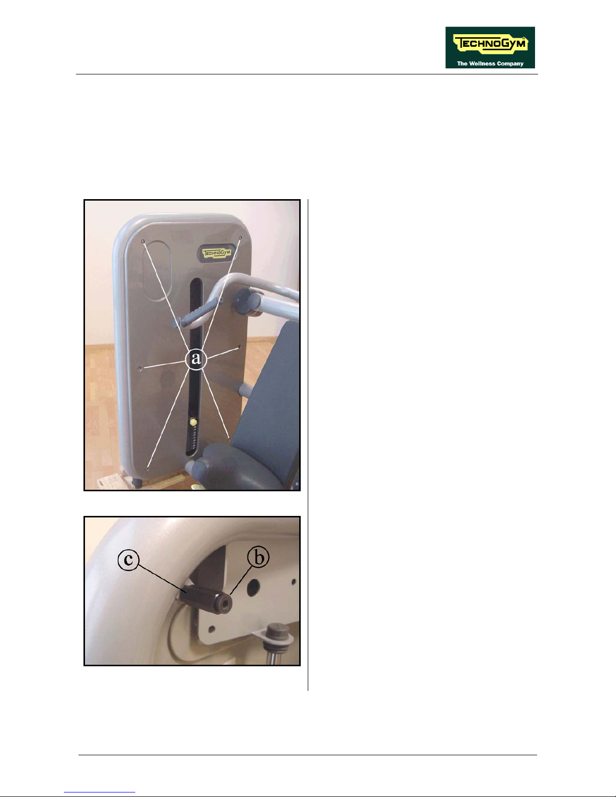
6.2. THE WEIGHT STACK CABLE IS NOT TAUT
This problem is due to lengthening of the weight stack cable. Therefore, to solve the problem you
must use the cable tension adjustment system.
If the cable is new, before adjusting its tension, it is necessary to do a few reps at
maximum load to “stretch” the cable itself.
Figure 6.2-1
1. Set the minimum weight: the only selected
weight will be the cross.
2. Loosen the counter-nut (a) using a 22-gauge
wrench.
3. Tighten the screw (b) at the end of the cable
so that the cable is taut and the cross raised.
4. Slowly loosen the screw (b) until the cable is
still taut, but the cross is resting on the
weight stack.
5. Tighten the counter-nut (a) using a 22-gauge
wrench.
Check the right tension of the cable,
making sure all the weight stack plates
are selecting by the weight stack pin.
Check the tension of the cable by carrying out a couple of repetitions with the minimum
weight, and then slowly resting the cross on the weight stack. The cross must rest firmly
on the weight stack, and the cable must be slightly taut.

ELEMENT LINE: Service & Maintenance Manual - rev. 1.2
Page 6.3
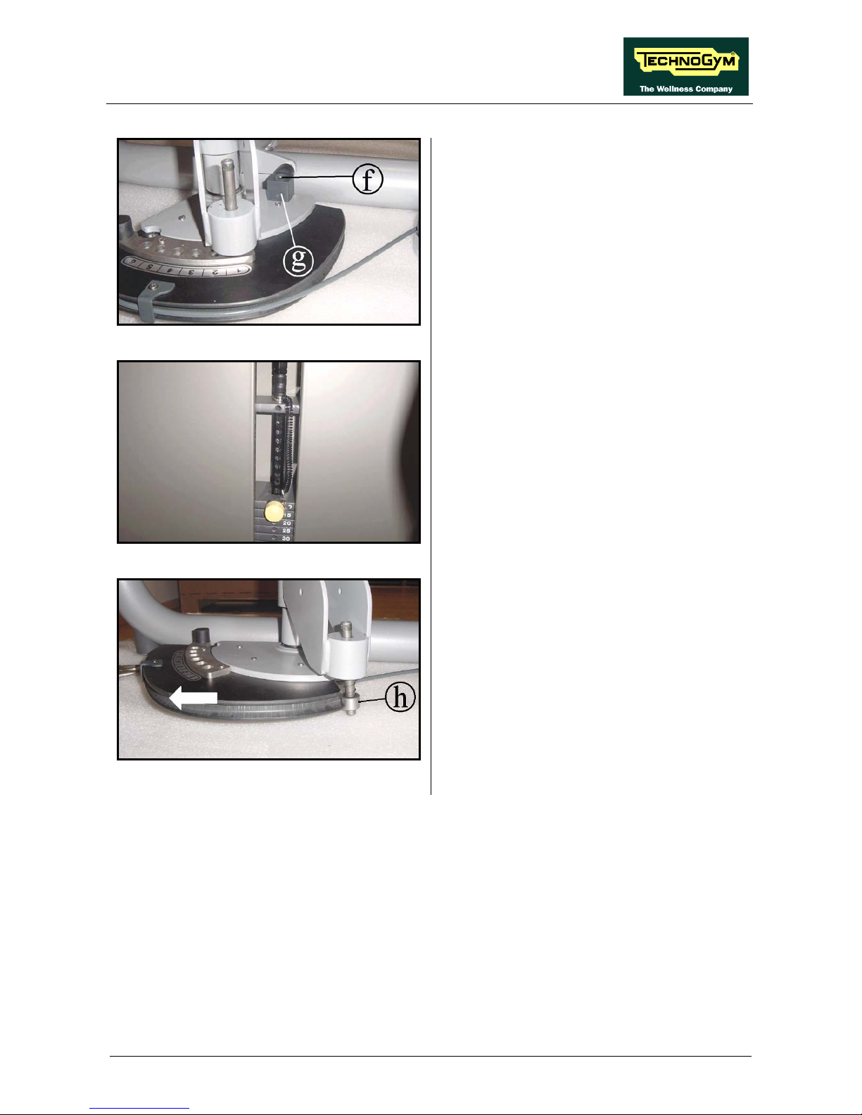
6.3. THE MACHINE IS NOT FLAT
To level the machine, you may adjust the height of the levelling foot as illustrated below:
Figure 6.3-1
1. Lift the machine on one side until you can
access the underside of the foot.
2. Loosen the foot cover piece (B).
3. Tighten or loosen the foot (A) until the
equipment is stable on the floor.
We recommend that 2 people carry out this operation.

ELEMENT LINE: Service & Maintenance Manual - rev. 1.2
Page 6.4
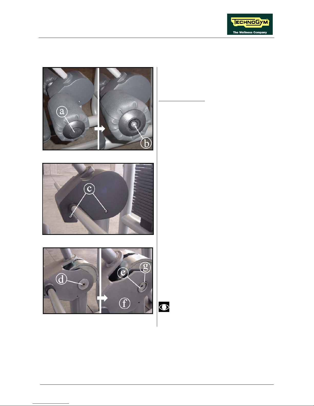
6.4. THE LEVERS OF DUAL-AXIS MACHINES ARE NOT
ALIGNED
This operation applies to Abductor, Adductor, Arm Curl, Arm Extension, Chest Press,
Low Row, Pectoral, Shoulder Press and Vertical Traction.
To align the levers of dual-axis machines, you may adjust the position of the stop buffers against
which the machine levers rest, as illustrated below:
Figure 6.4-1
1. Loosen the counter-nut (a) on both sides,
using a 17-gauge wrench.
2. Adjust the position of the 2 stop buffers (b),
tightening or loosening them until the levers
are aligned.
Use a lever for a more precise check.
3. When the adjustment is complete, tighten the
counter-nuts (a) once again.
This procedure may also be carried out
to adjust the starting position of the
levers on the other machines.
ELEMENT LINE: Service & Maintenance Manual - rev. 1.2
Page 7.1
7. SPECIAL OPERATIONS
The term special operations refers to those procedures whose correct execution is fundamental for
the safe and reliable operation of the machine.
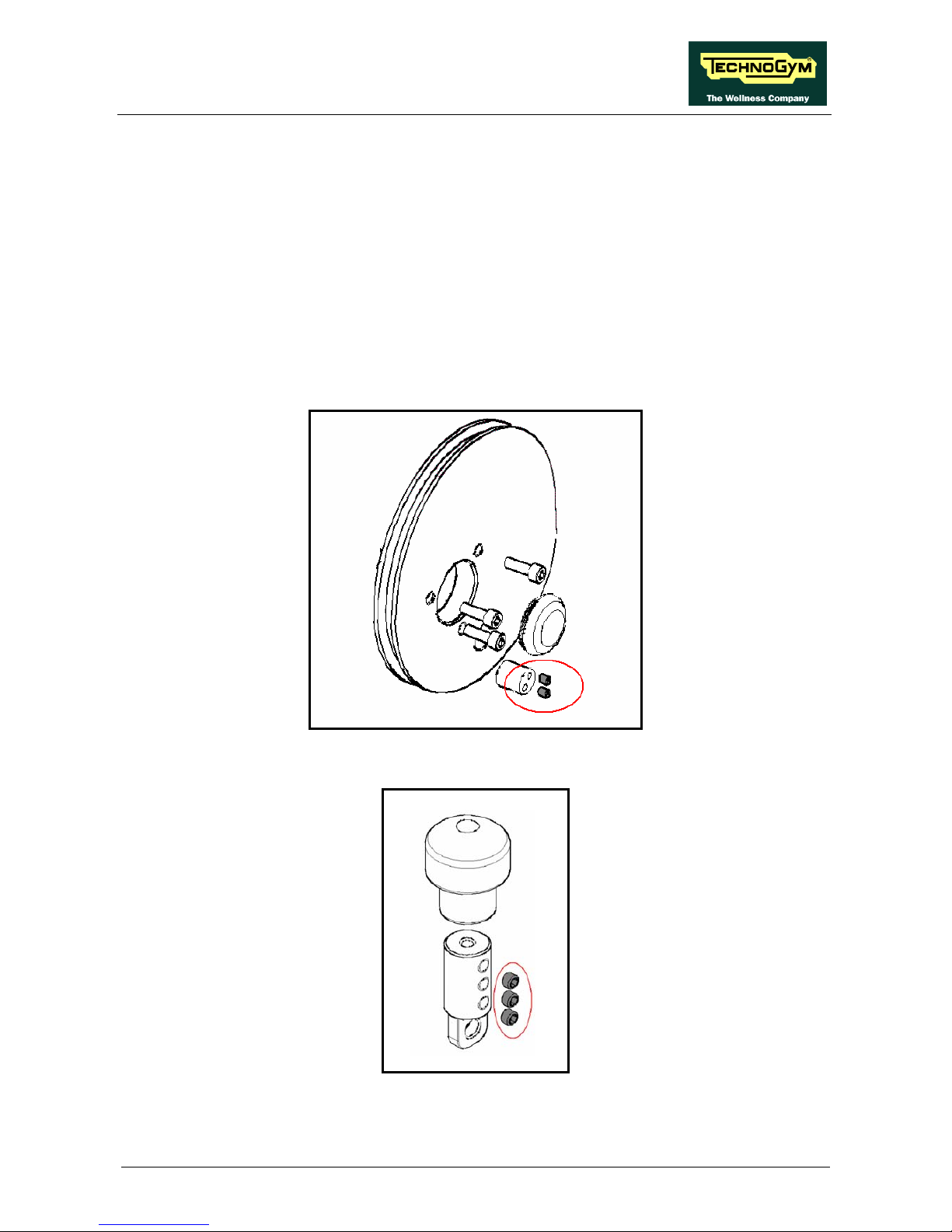
7.1. LOCKING DOWN THE CABLE FIXING DOWELS
At least one end of the weight stack cable is fixed to the wheel or to a stop by means of the dowel
screws highlighted in grey and circled in the figures below. The fixing dowels must be carefully
locked down to prevent them from working loose and allowing the cable to come out, causing
problems to the user.
Figure 7.1-1
Figure 7.1-2

ELEMENT LINE: Service & Maintenance Manual - rev. 1.2
Page 7.2
Figure 7.1-3
Use a torque wrench to ensure that the dowels are locked down with the prescribed torque of 16.5
Nm / 12.2 ft.lbs.
7.2. LOCKING DOWN THE PULLEYS
The screws of the pulleys, highlighted in grey and circled in the figure below, must be carefully
locked down to prevent them from working loose and causing problems to the user.
Figure 7.2-1
Use a torque wrench to ensure that the screws are locked down with the prescribed torque of 50 Nm
/ 36.9 ft.lbs.

ELEMENT LINE: Service & Maintenance Manual - rev. 1.2
Page 7.3
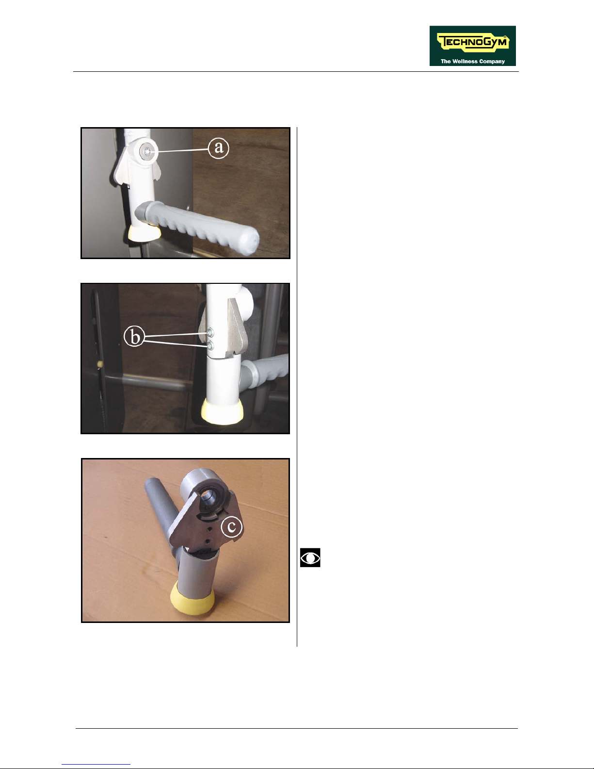
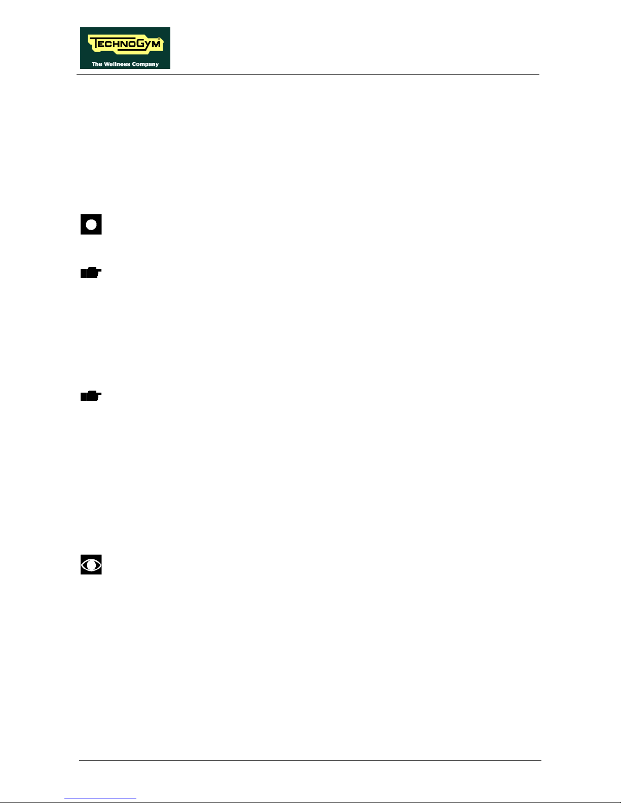
7.3. LOCKING DOWN THE DOWELS ON THE ARM
EXTENSION LEVER
Each lever of the Arm Extension machine has a joint consisting of 2 threaded ends and one with an
intermediate steel cable. This must be fixed without excessive force, to avoid over-tightening and
damaging the steel cable. Therefore, lock down until the end of the thread, and then use the 3 dowel
screws circled in the figure below to secure the components in place.
Figure 7.3-1
Use a torque wrench to check that they are locked down with the prescribed torque of 13 Nm / 9.6
ft.lbs.

ELEMENT LINE: Service & Maintenance Manual - rev. 1.2
Page 7.4
Page intentionally left blank

ELEMENT LINE: Service & Maintenance Manual - rev. 1.2
Page 8.1
8. WEIGHT STACK CABLE
8.1. LENGTH OF THE WEIGHT STACK CABLES
Standard weight stack
Code Machine
code Length (mm)
MA05
Adductor 0R000131AA 4800
MA10
Abductor 0R000115AA 4400
0R000111AA
(1)
1090
MA15
Shoulder Press
0R000112AA 3360
0R000111AA
(1)
3050
MA20
Chest Press
0R000112AA 3360
0R000111AA
(1)
3050
MA25
Vertical Traction
0R000118AA 3000
MA30
Leg Extension 0R000119AA 3500
MA35
Leg Curl 0R000118AA 3000
MA40
Lat Machine 0R000130AA 2400
MA45
Lower Back 0R000119AA 3500
0R000128AC crimpato
MA50
Leg Press
0R000008
(1)
1500
0R000111AA
(1)
4100
MA55
Arm Curl
0R000112AA 3360
0R000111AA
(1)
4030
MA60
Arm Extension
0R000112AA 3360
MA65
Abdominal Crunch 0R000119AA 3500
0R000112AA 3360
MA70
Pectoral
0R000126AB 775
MA75
Glute 0R000124AA 2100
MA80
Ercolina
0R000111AA
(1)
6300
MA85
Ercolina Crossover Cable
0R000111AA
(1)
1140
MA90
Ercolina Rehab
0R000111AA
(1)
8300
MA95
Low Row 0R000131AA 4800
(1) You must indicate the length when ordering this cable.

ELEMENT LINE: Service & Maintenance Manual - rev. 1.2
Page 8.2
8.2. ROUTING OF THE WEIGHT STACK CABLE
The following pages illustrate the routing of the weight stack cables through the pulleys for each
machine, for use as reference when replacing the machine cables.
8.2.1. MA05 – ADDUCTOR
MA05 – ADDUCTOR

ELEMENT LINE: Service & Maintenance Manual - rev. 1.2
Page 8.3
8.2.2. MA10 – ABDUCTOR
MA10 – ABDUCTOR
8.2.3. MA15 – SHOULDER PRESS
MA15 – SHOULDER PRESS

ELEMENT LINE: Service & Maintenance Manual - rev. 1.2
Page 8.4
8.2.4. MA20 – CHEST PRESS
MA20 – CHEST PRESS
8.2.5. MA25 – VERTICAL TRACTION
MA25 – VERTICAL TRACTION

ELEMENT LINE: Service & Maintenance Manual - rev. 1.2
Page 8.5
8.2.6. MA30 – LEG EXTENSION
MA30 – LEG EXTENSION
8.2.7. MA35 – LEG CURL
MA35 – LEG CURL

ELEMENT LINE: Service & Maintenance Manual - rev. 1.2
Page 8.6
8.2.8. MA40 – LAT MACHINE
MA40 – LAT MACHINE
8.2.9. MA45 – LOWER BACK
MA45 – LOWER BACK

ELEMENT LINE: Service & Maintenance Manual - rev. 1.2
Page 8.7
8.2.10. MA50 – LEG PRESS
MA50 – LEG PRESS
8.2.11. MA55 – ARM CURL
MA55 – ARM CURL

ELEMENT LINE: Service & Maintenance Manual - rev. 1.2
Page 8.8
8.2.12. MA60 – ARM EXTENSION
MA60 – ARM EXTENSION
8.2.13. MA65 – ABDOMINAL CRUNCH
MA65 – ABDOMINAL CRUNCH

ELEMENT LINE: Service & Maintenance Manual - rev. 1.2
Page 8.9
8.2.14. MA70 – PECTORAL
MA70 – PECTORAL
8.2.15. MA75 – GLUTE
MA75 – GLUTE

ELEMENT LINE: Service & Maintenance Manual - rev. 1.2
Page 8.10
8.2.16. MA80 – ERCOLINA
MA80 – ERCOLINA
8.2.17. MA85 – ERCOLINA CROSS OVER CABLE
MA85 – ERCOLINA CROSS OVER CABLE

ELEMENT LINE: Service & Maintenance Manual - rev. 1.2
Page 8.11
8.2.18. MA90 – ERCOLINA REHAB
MA90 – ERCOLINA REHAB
8.2.19. MA95 – LOW ROW
MA95 – LOW ROW

ELEMENT LINE: Service & Maintenance Manual - rev. 1.2
Page 8.12
Page intentionally left blank

ELEMENT LINE: Service & Maintenance Manual - rev. 1.2
Page 9.1
9. MAINTENANCE
To keep the machine in perfect working order and forestall possible problems it is necessary to
carry out the scheduled maintenance operations described below. The maintenance operations can
essentially be classified according to the frequency with which they need to be performed:
• Daily maintenance operations;
• Weekly maintenance operations;
• Monthly maintenance operations;
• Twice yearly maintenance operations.
The operations require different levels of operator qualification. The following paragraphs describe
the recommended procedures.
9.1. DAILY MAINTENANCE OPERATIONS
These operations can be carried out by the machine owner and do not require any
special skills.
The daily machine maintenance consists of simple external cleaning, for the purposes of general
hygiene.
For the daily maintenance of the machine, proceed as follows:
9.1.1. CLEANING UPHOLSTERY
1. We recommend that you perform this operation daily.
2. Clean the upholstery of the machine using a cloth moistened with Clean Well.
CAUTION: do not use alcohol, benzene, or chemical products in general.

ELEMENT LINE: Service & Maintenance Manual - rev. 1.2
Page 9.2
9.2. WEEKLY MAINTENANCE OPERATIONS
These operations can be carried out by the machine owner and do not require any
special skills.
The weekly machine maintenance operations consists of simple cleaning, lubrication and checking
the emergency stop to ensure the correct and safe functioning of the machine.
For the weekly maintenance operations, proceed as follows:
9.2.1. CLEANING THE FRAME AND PAINTED PARTS
1. Clean the frame and painted parts of the machine using a cloth moistened with Clean Well.
CAUTION: do not use alcohol, benzene, or chemical products in general.

ELEMENT LINE: Service & Maintenance Manual - rev. 1.2
Page 9.3
9.3. MONTHLY MAINTENANCE OPERATIONS
These operations can be carried out by the machine owner and do not require any
special skills.
The monthly machine maintenance operations consists of simple cleaning, lubrication and
checking the state of wear to ensure the correct and safe functioning of the machine.
For the monthly maintenance of the machine, proceed as follows:
9.3.1. CHECK THE CROSS, BARS AND WEIGHT STACK PLATES
1. Check the wear status of the cross bushings and weight stack plates. Repair and/or replace any
worn parts.
2. Check the wear status of the chrome plating of the weight stack bars. Repair and/or replace any
worn parts.
3. Check the wear status of the weight stack bars and weight stack support stops. Repair and/or
replace any worn parts.
4. Make sure the weight stack bars are firmly fastened. Repair and/or replace any worn parts.
5. Use a paper towel slightly dampened with ethyl alcohol to clean the weight stack bars of the
machine, removing dust and grime.
CAUTION: remove any surface rust spots with a metal scrubber.
6. Lubricate the bars and bushings of the plates and cross using the oil found in the service box.
7. Check the adhesive label indicating the load corresponding to the weight stack plates. Replace
any worn parts.
9.3.2. CHECK THE CABLES
1. Check the wear status of the machine cables, paying special attention to any hardened spots or
cracks in the protective plastic of the cable. Replace any worn parts.
2. Check the passage of the machine cables through cams, pulleys and/or the terminals connected
to ball joints.
3. Check the tension of the machine cables.
9.3.3. CHECK THE MECHANISMS
1. Check the wear status of the machine mechanisms: lever arms, shafts, lever systems. Repair
and/or replace any worn parts.
2. Lubricate the mechanisms using MOLYKOTE LONGTERM W 2.
9.3.4. CHECK THE GAS SPRINGS
1. Check the efficiency of the gas spring, making sure it sufficiently cushions the stem return to its
outward position.
2. Clean the stem using a dry cloth.
CAUTION: do NOT lubricate the gas spring stem for any reason.
ELEMENT LINE: Service & Maintenance Manual - rev. 1.2
Page 9.4
9.3.5. CHECK THE WEIGHT STACK STOPS
1. Check the wear status of the stops. Repair and/or replace any worn parts.
2. Check the position of the stops and make sure they are firmly fastened in place.
9.3.6. CHECK THE LEG PRESS SEAT MECHANISM
1. Check the wear status of the support bars and seat pulleys. Repair and/or replace any worn
parts.
2. Clean the seat support bars using alcohol.
CAUTION: lubricate the support bars with silicon oil.
9.3.7. CHECKING THE SEAT MECHANISM ON LOW MACHINES
Perform this check on the Leg Extension, Leg Curl.
1. Check the wear status of the pulleys, support bars and seat guide. Repair and/or replace any
worn parts.
2. Clean the seat support guide bars using alcohol.
3. Lubricate the seat support guide bars using the oil found in the box service.
9.3.8. CHECKING THE SEAT MECHANISM ON TALL MACHINES
Perform this check on the Arm Curl, Arm Extension, Chest Press, Low Row, Pectoral,
Shoulder Press, Vertical Traction, Scott Bench, Inclined Bench Press and Vertical
Bench.
1. Check the wear status of the seat guide pulleys. Repair and/or replace any worn parts.
2. Clean the seat guide pulleys using alcohol.
3. Lubricate the seat support guide bars using the oil found in the box service.
9.3.9. CHECKING THE UPHOLSTERY
1. Check the wear status of the upholstery. Replace any worn parts.
9.3.10. CHECKING VARIOUS RUBBER PARTS
These operations apply to handles, knobs, mats, frame guards, bell covers, feet …
1. Check the wear status of the rubber parts used on the machine. Repair and/or replace any worn
parts.

ELEMENT LINE: Service & Maintenance Manual - rev. 1.2
Page 9.5
9.4. TWICE-YEARLY MAINTENANCE OPERATIONS
These operations can only be carried out by a qualified technician specifically trained by
Technogym and authorized to carry out machine installation and adjustments, as well as
special maintenance operations or repairs which require special knowledge of the
machine, its operation, safety systems and working procedures.
The six-monthly maintenance operations involve checking the functioning, wear and tension of the
mechanical components so as to ensure the correct and safe operation of the machine.
For the six-monthly maintenance of the machine, proceed as follows:
9.4.1. CHECK THE PULLEYS
1. Check the wear status of the pulley grooves. Repair and/or replace any worn parts.
9.4.2. CHECK THE CAM GROUP
1. Check the wear status of the cam grooves. Repair and/or replace any worn parts.
2. Make sure all parts in the cam group are firmly tightened.
9.4.3. CHECK THE LEVER STOPS
1. Check the wear status of the lever stops. Repair and/or replace any worn parts.
2. Check the position of the stops and make sure they are firmly fastened in place.
9.4.4. REPLACING THE CABLES
1. Replace the machine cables once a year if the machines are used intensively, every 2 years
under normal use.
9.4.5. LUBRICATING THE RELEASE SYSTEMS
Perform this check on:
• Lever start position adjustment on Adductor and Abductor;
• Roller position adjustment on Leg Extension, Leg Curl, Lower Back.
1. On Adductor and Abductor, lubricate the starting position selection pin using MOLYKOTE
LONGTERM W 2.
2. On Leg Extension, Leg Curl and Lower Back disassemble the rubber bell guard and lubricate
the start position selection pin using MOLYKOTE LONGTERM W 2.

ELEMENT LINE: Service & Maintenance Manual - rev. 1.2
Page 9.6
9.4.6. SCREW AND BOLT CHECK
1. Make sure that the screws and bolts are firmly tightened, especially in the weight stack and seat
adjustment areas, and around moving parts in general. Tighten any that are loose.
9.4.7. CHECKING FOR MECHANISM PLAY
1. Make sure that the machine mechanisms (lever arms, shafts, starting position adjustments,
leverages) have no play. Repair and/or replace any worn parts.
9.4.8. CHECKING CROSS ALIGNMENT
1. Do not select any weight, and lift the cross. Make sure that the selector rod is properly centred
over the plate hole, and that all plates in the weight stack may be selected without any strain by
the selection knob. Force it to the centre by hand.

ELEMENT LINE: Service & Maintenance Manual - rev. 1.2
Page 10.1
10. APPENDIX
10.1. TOOLS TO USE
The following tools are necessary to carry out all disassembly, adjustment and maintenance
operations on the machines:
• Small Flat Screwdriver;
• Medium Philips screwdriver;
• 13mm wrench;
• 17mm wrench;
• 22mm wrench;
• 30mm wrench;
• 3mm hexagonal wrench;
• 4mm hexagonal wrench;
• 5mm hexagonal wrench;
• 6mm hexagonal wrench;
• 8mm hexagonal wrench;
• 12mm hexagonal wrench;
• 20mm socket wrench for ring nut;
• 45mm socket for ring nut;
• Pointed tool;
• Pliers;
• Torque wrench;
• Hammer.
Tool measurements are expressed in mm.

ELEMENT LINE: Service & Maintenance Manual - rev. 1.2
Page 10.2

ELEMENT LINE: Service & Maintenance Manual - rev. 1.2
Page 10.3
Page intentionally left blank


0SM00384AA-UK
TECHNOGYM S.p.A.
Via G. Perticari, 20
47035 Gambettola (FC)
ITALIA
Tel.: +39 - 0547 650638
Fax: +39 - 0547 650150
e-mail: service@technogym.com
 Loading...