


SERVICE & MAINTENANCE MANUAL
REV. 1.1


The information contained in this manual is intended for QUALIFIED TECHNICIANS who have
completed a specific TECHNOGYM training course and are authorized to perform machine start-
up and adjustment procedures as well as extraordinary maintenance or repairs which require a
thorough knowledge of the machine, its operation, its safety devices and working procedures.
CAREFULLY READ THE INFORMATION CONTAINED IN
THIS MANUAL BEFORE PERFORMING ANY MAINTENANCE
PROCEDURES ON THE MACHINE
DANGEROUS VOLTAGES
PRESENT
NOTE
The information contained in this document is subject to change without notice.
Technogym does not guarantee this documentation in any way. Technogym shall not be held
responsible for any errors contained in this manual and declines all liability for accidents or
damages resulting from the supply, characteristics or use of this manual.
This document contains proprietary information that is protected by copyright. All rights reserved.
No part of this document may be photocopied, reproduced or translated into another language
without the prior written consent of Technogym.
The Technogym™ trademark is property of Technogym S.p.A.
The Jog Excite™ trademark is property of Technogym S.p.A.


JOG EXCITE: Service & Maintenance Manual - rev. 1.1
Contents
1. GENERAL NOTICES............................................................................................................................................. 1.1
1.1. INTRODUCTION................................................................................................................................................1.1
1.2. RECOMMENDATIONS ....................................................................................................................................... 1.1
1.3. GENERAL RULES FOR REPAIR PROCEDURES......................................................................................................1.2
2. TECHNICAL CHARACTERISTICS.................................................................................................................... 2.1
2.1. PRODUCT CODES.............................................................................................................................................. 2.1
2.2. FEATURES AND FUNCTIONS. ............................................................................................................................2.2
2.3. MECHANICAL CHARACTERISTICS.....................................................................................................................2.3
2.4. CONFORMITY REGULATIONS............................................................................................................................ 2.3
2.5. AMBIENT SPECIFICATIONS ...............................................................................................................................2.3
2.6. WIRING DIAGRAM............................................................................................................................................2.4
2.6.1. Lower assembly................................................................................................................................2.4
2.6.2. Upper assembly: LED ARM version.................................................................................................2.5
2.7. WIRING............................................................................................................................................................2.6
3. PRINCIPLES OF OPERATION............................................................................................................................ 3.1
3.1. BLOCK DIAGRAM.............................................................................................................................................3.1
3.1.1. Display board................................................................................................................................... 3.2
3.1.2. TGS reader.......................................................................................................................................3.2
3.1.3. HS / cardio receiver board...............................................................................................................3.2
3.1.4. Emergency switch.............................................................................................................................3.3
3.1.5. Belt motor.........................................................................................................................................3.3
3.1.6. Elevation motor................................................................................................................................3.3
3.1.7. Limit switch.......................................................................................................................................3.3
3.1.8. AT driver...........................................................................................................................................3.3
3.1.9. Power supply box..............................................................................................................................3.5
3.2. TREAD BELT MOTOR DRIVE.............................................................................................................................. 3.6
3.2.1. Mechanics.........................................................................................................................................3.6
3.2.2. Controls............................................................................................................................................3.6
3.2.3. The signals involved.........................................................................................................................3.7
3.3. ELEVATION MOTOR DRIVE............................................................................................................................... 3.8
3.3.1. Mechanics.........................................................................................................................................3.8
3.3.2. Control..............................................................................................................................................3.8
3.3.3. The reset procedure..........................................................................................................................3.9
3.3.4. The signals involved.........................................................................................................................3.9
3.4. EMERGENCY STOP MANAGEMENT..................................................................................................................3.11
3.4.1. Control............................................................................................................................................3.11
3.4.2. The signals involved.......................................................................................................................3.12
3.1.8.1. AT driver board............................................................................................................................................................. 3.4
3.1.8.2. AT power supply board................................................................................................................................................. 3.5
3.1.8.3. Fans................................................................................................................................................................................ 3.5
3.1.8.4. Breaking resistor ...........................................................................................................................................................3.5
4. ACCESSORIES .......................................................................................................................................................4.1
4.1. CARDIO THEATER CONNECTION.......................................................................................................................4.1
4.2. PC LINK FOR PROGRAMMING ...........................................................................................................................4.1
4.3. MONITOR PLUG FOR CSAFE PORT ....................................................................................................................4.2
5. INSTALLATION INSTRUCTIONS...................................................................................................................... 5.1
5.1. SPECIFICATIONS AND REQUIREMENTS..............................................................................................................5.1
5.2. INSTALLATION.................................................................................................................................................5.2
5.3. FIRST POWER-ON .............................................................................................................................................5.2
Page i

JOG EXCITE: Service & Maintenance Manual - rev. 1.1
6. TROUBLESHOOTING ..........................................................................................................................................6.1
6.1. TROUBLESHOOTING SERVICE MENU.................................................................................................................6.2
6.1.1. Automatic Tests.................................................................................................................................6.3
6.1.2. Manual Test......................................................................................................................................6.4
6.2. THE DISPLAY FAILS TO ILLUMINATE.................................................................................................................6.5
6.3. “PRESS A KEY” MESSAGE ON THE DISPLAY ..................................................................................................6.9
6.4. “THE EQUIPMENT IS BLOCKED” MESSAGE ON THE DISPLAY .................................................................6.10
6.5. AT DRIVER ERROR.........................................................................................................................................6.11
6.5.1. Error OH........................................................................................................................................6.13
6.5.2. Errors OC - OLi - OLm - Ot - OCH - MST - SHC.........................................................................6.14
6.5.3. Error UU........................................................................................................................................6.15
6.5.4. Error OU........................................................................................................................................6.16
6.5.5. Error OtM.......................................................................................................................................6.17
6.5.6. Error OLr.......................................................................................................................................6.18
6.5.7. Error PE.........................................................................................................................................6.19
6.5.8. Error EM........................................................................................................................................6.20
6.6. TREAD BELT MOTOR IS JERKING.....................................................................................................................6.21
6.7. “GRADIENT NOT WORKING” MESSAGE ON THE DISPLAY .......................................................................6.22
6.8. THE MACHINE DOES NOT READ THE TGS.........................................................................................................6.24
6.9. THERE IS NO HEART RATE SIGNAL.................................................................................................................. 6.26
6.9.1. Telemetric receiver HFU................................................................................................................6.26
6.9.2. Hand sensor....................................................................................................................................6.27
6.10. THE TELEMETRIC HR SIGNAL IS INCORRECT ...................................................................................................6.29
6.1.1.1. I2C Device Test............................................................................................................................................................. 6.3
6.1.1.2. UpDown Test ................................................................................................................................................................6.3
6.1.1.3. Inverter Test ..................................................................................................................................................................6.3
6.1.1.4. LED Test ....................................................................................................................................................................... 6.4
6.1.1.5. Serial Ports Test............................................................................................................................................................. 6.4
6.1.2.1. Man. Keyboard Test......................................................................................................................................................6.4
7. DISASSEMBLY OF COMPONENTS................................................................................................................... 7.1
7.1. DISASSEMBLING THE DISPLAY .........................................................................................................................7.1
7.2. DISASSEMBLING THE CIRCUIT BOARDS OF THE DISPLAY ..................................................................................7.2
7.3. DISASSEMBLING THE KEYBOARD.....................................................................................................................7.3
7.4. DISASSEMBLING THE EMERGENCY BUTTON .....................................................................................................7.4
7.5. DISASSEMBLING THE CARDIO RECEIVER/HAND SENSOR BOARD .......................................................................7.5
7.6. DISASSEMBLING THE SENSORS.........................................................................................................................7.7
7.7. DISASSEMBLING THE READY TO RUN BOARD ..................................................................................................7.8
7.8. SMONTAGGIO MANIGLIONI ..............................................................................................................................7.9
7.9. DISASSEMBLING THE MOTOR GUARD............................................................................................................. 7.10
7.10. DISASSEMBLING THE MOTOR COMPARTMENT FAN.........................................................................................7.11
7.11. DISASSEMBLING THE LIMIT SWITCH...............................................................................................................7.12
7.12. DISASSEMBLING THE ELECTRICAL BOX.......................................................................................................... 7.13
7.13. DISASSEMBLING THE ELECTRONICS BOARDS ................................................................................................. 7.14
7.14. DISASSEMBLING THE POWER SUPPLY BOX ..................................................................................................... 7.16
7.15. DISASSEMBLING THE TREAD BELT MOTOR.....................................................................................................7.17
7.16. DISASSEMBLING THE ELEVATION MOTOR ...................................................................................................... 7.18
7.17. DISASSEMBLING THE TREAD BELT GROUP...................................................................................................... 7.19
8. ADJUSTMENTS...................................................................................................................................................... 8.1
8.1. TENSIONING A NEW TREAD BELT ..................................................................................................................... 8.1
8.2. TENSIONING A USED TREAD BELT ....................................................................................................................8.2
8.3. CENTERING THE TREAD BELT........................................................................................................................... 8.3
8.4. POSITION OF THE LIMIT SWITCH.......................................................................................................................8.4
9. MACHINE CONFIGURATION............................................................................................................................ 9.1
9.1. USER MENU CONFIGURATION...........................................................................................................................9.1
9.1.1. Language..........................................................................................................................................9.1
9.1.2. Distance............................................................................................................................................ 9.2
Page ii

JOG EXCITE: Service & Maintenance Manual - rev. 1.1
9.1.3. Maximum exercise time....................................................................................................................9.2
9.1.4. Pause time ........................................................................................................................................9.2
9.1.5. Default age.......................................................................................................................................9.3
9.1.6. Default weight...................................................................................................................................9.3
9.1.7. Default time......................................................................................................................................9.3
9.1.8. Default calories................................................................................................................................9.4
9.1.9. Default distance................................................................................................................................9.4
9.1.10. Enable TGS.......................................................................................................................................9.4
9.1.11. Enable keyboard ...............................................................................................................................9.5
9.1.12. Modifiable target heart rate.............................................................................................................9.5
9.1.13. Enable custom messages ..................................................................................................................9.5
9.1.14. Enable up/down motor......................................................................................................................9.6
9.1.15. Resetting parameters to default values.............................................................................................9.6
9.1.16. Format P&P.....................................................................................................................................9.6
9.1.17. User Detect ....................................................................................................................................... 9.6
9.1.18. SN.....................................................................................................................................................9.7
9.1.19. Ready2Run........................................................................................................................................9.7
9.2. SERVICE MENU CONFIGURATION......................................................................................................................9.8
9.2.1. Low kit parameter.............................................................................................................................9.9
9.2.2. UpDown settings.............................................................................................................................9.10
9.2.3. Usage data......................................................................................................................................9.12
9.2.4. Errors log.......................................................................................................................................9.13
9.2.5. Standard settings............................................................................................................................9.15
9.2.6. Low kit menu...................................................................................................................................9.15
9.2.7. High kit version ..............................................................................................................................9.20
9.2.8. BOOT version ................................................................................................................... .............. 9.20
9.2.9. Key Reader Version........................................................................................................................9.20
9.3. DRIVER AUTOTUNING....................................................................................................................................9.21
9.4. RECALL PARAMETERS....................................................................................................................................9.21
9.5. DEFAULT PARAMETERS ................................................................................................................................. 9.22
9.2.1.1. Read from low kit.......................................................................................................................................................... 9.9
9.2.1.2. Write to low kit.............................................................................................................................................................. 9.9
9.2.1.3. Default setting ............................................................................................................................................................... 9.9
9.2.1.4. Table of configuration parameters..............................................................................................................................9.10
9.2.2.1. Read from low kit........................................................................................................................................................ 9.11
9.2.2.2. Write to low kit............................................................................................................................................................ 9.11
9.2.2.3. Default setting ............................................................................................................................................................. 9.11
9.2.3.1. Read from low kit........................................................................................................................................................ 9.12
9.2.3.2. Write to low kit............................................................................................................................................................ 9.12
9.2.3.3. Machine usage data..................................................................................................................................................... 9.13
9.2.4.1. Read from low kit........................................................................................................................................................ 9.13
9.2.4.2. Reset errors.................................................................................................................................................................. 9.14
9.2.4.3. COM.Fault................................................................................................................................................................... 9.14
9.2.4.4. View Errors ................................................................................................................................................................. 9.14
9.2.6.1. Low kit version............................................................................................................................................................ 9.16
9.2.6.2. Config. registers..........................................................................................................................................................9.16
10. SCHEDULED MAINTENANCE .........................................................................................................................10.1
10.1. DAILY MAINTENANCE OPERATIONS ...............................................................................................................10.1
10.1.1. Setting up the operation..................................................................................................................10.1
10.1.2. External cleaning operations..........................................................................................................10.1
10.2. WEEKLY MAINTENANCE OPERATIONS............................................................................................................10.2
10.2.1. Checking the “Emergency stop”.................................................................................................... 10.2
10.2.2. Complete operation........................................................................................................................10.2
10.3. MONTHLY MAINTENANCE OPERATIONS .........................................................................................................10.3
10.3.1. Internal cleaning operations ..........................................................................................................10.3
10.3.2. Checking the state of wear..............................................................................................................10.3
10.3.3. Checking the operation of the cardiotester receiver.......................................................................10.3
10.3.4. Checking the operation of the hand sensor receiver......................................................................10.3
10.4. TWICE-YEARLY MAINTENANCE OPERATIONS................................................................................................. 10.4
10.4.1. carrying out the monthly maintenance procedure..........................................................................10.4
10.4.2. Checking the working conditions....................................................................................................10.4
Page iii

JOG EXCITE: Service & Maintenance Manual - rev. 1.1
10.4.3. Checking the wiring and connections.............................................................................................10.4
10.4.4. Checking the wear and lubrication of the tread belt and running deck.........................................10.5
10.4.5. Checking the wear of the driving roller..........................................................................................10.5
10.4.6. Checking the wear of the rear roller..............................................................................................10.5
10.4.7. Checking the shock absorbers........................................................................................................ 10.5
10.4.8. Checking the tread belt motor drive-belt........................................................................................10.5
10.4.9. Checking and centering the tread belt............................................................................................10.5
10.4.10. Checking the display.......................................................................................................................10.6
11. APPENDIX............................................................................................................................................................. 11.1
11.1. UPDATING THE SW.........................................................................................................................................11.1
11.2. TOOLS TO USE................................................................................................................................................11.2
Page iv

JOG EXCITE: Service & Maintenance Manual - rev. 1.1
1. GENERAL NOTICES
1.1. INTRODUCTION
This document is reserved for Technogym Service technicians, and is intended to provide
authorized personnel with the necessary information to correctly carry out repairs and maintenance.
A thorough knowledge of the technical information contained in this manual is essential for
completing the professional training of the operator.
In order to facilitate consultation, the paragraphs are accompanied by schematic drawings which
illustrate the procedure being described.
This manual contains notices and symbols which have a specific meanings:
WARNING: non observance may result in accident or injury.
ATTENTION: non observance may cause damage to the machine.
Information about the operation in progress.
OBSERVE: observation about the operation in progress.
1.2. RECOMMENDATIONS
Technogym recommends the following steps for planning repair procedures:
• Carefully evaluate the customer’s description of the machine malfunction and ask all the
necessary questions to clarify the symptoms of the problem.
• Clearly diagnose the causes of the problem. This manual provides the fundamental theoretical
basis, which must then be integrated by personal experience and attendance at the training
courses periodically offered by Technogym.
• Rationally plan the repair procedure so as to minimize the downtime necessary for procuring
spare parts, preparing tools, etc.
• Access the component to be repaired, avoiding any unnecessary operations. In this regard it will
be useful to refer to the disassembly sequence described in this manual.
Page 1.1

JOG EXCITE: Service & Maintenance Manual - rev. 1.1
1.3. GENERAL RULES FOR REPAIR PROCEDURES
1. Always mark any parts or positions which may be confused with each other at the time of
reassembly.
2. Use original Technogym spare parts and lubricants of the recommended brands.
3. Use special tools where specified.
4. Consult the Technical Newsletters, which may contain more up-to-date information on
adjustments and maintenance than those contained in this manual.
5. Before starting the repair procedure, make sure that the recommended tools are available and in
good condition.
6. For the procedures described in this manual, use only the specified tools.
OBSERVE: The tool sizes quoted in this manual are expressed in mm.
Page 1.2

JOG EXCITE: Service & Maintenance Manual - rev. 1.1
2. TECHNICAL CHARACTERISTICS
2.1. PRODUCT CODES
The machine codes take into account all the possible variants and options available for the products.
The machine code, which does not include the Serial Number, consists of 16 alphanumeric
characters arranged as follows:
Characters description key to values
1,2 Machine type: Excite
3,4 Product version
5 Type of power supply
6 Type of display
7
8, 9 Color of the frame
10, 11 Color of the paddings
12 Color of the guards
13 Type of TV model
14,15 Language
16 Type of packaging
The above coding is used for the entire Excite line. For this reason, options not relevant
to the Jog machine have also been included.
For example, a possible product code would be:
which is interpreted as follows:
Device for downloading data used by the
Wellness System
D443ELNAL0000UKE
D4
43 = Jog Excite 700
E = European driver
L = LED display
N = not available
T = TGS
AL = aluminium
00 = none
0 = none
0 = none
BR = portoguese
CN = chinese
DE = german
ES = spanish
FR = franch
IT = italian
JP = japanese
NL = dutch
RU = russian
UK = british english
US = american english
I = Italy
E = international (standard)
S = international (overseas)
0 = none
Page 2.1

JOG EXCITE: Service & Maintenance Manual - rev. 1.1
D4 43 E L N AL 00 0 0 UK E
British English language
no TV model
guard color
no paddings
aluminum frame color
Not interfaced to TGS key reader
LED display
European driver
Jog 700 model
Excite
2.2. FEATURES AND FUNCTIONS.
Mains voltage
Frequency
Consumption
Speed
Incline
Fast track control
Hand sensor
Cardio receiver
Ready to Run
Calorie coach
Runner Detection
CHARACTERISTIC
Training
programs
Test functions
Goal (Time, Distance, Calorie)
standard international packing
VERSION
700
180-260 Vac
50-60 Hz
2200 W
0.8-18 Km/h
0.5-12 mph
0-15 %
NO
YES
HFU
YES
YES
YES
Quick Start
6 profiles
CPR
Test
Fitness test
Page 2.2

JOG EXCITE: Service & Maintenance Manual - rev. 1.1
2.3. MECHANICAL CHARACTERISTICS
Width
Length
Height
Running deck height from the floor
Weight
2.4. CONFORMITY REGULATIONS
The machine conforms to the following standards:
Standards
Directives
In addition:
• Electrical isolation class under EN60335-1: Classe I;
• Protection rating: IP20.
Europe USA
EN60335-1
EN55014-1
EN55014-2
EN61000-3-2
EN61000-3-3
EN957-1
EN957-6 class SA
73/23/CEE
89/336/CEE
98/37/CEE
85.9 cm - 34 in
210 cm - 83 in
141.5 cm - 56 in
21.5 cm – 8.5 in
164 Kg - 361 lbs
UL 60601-1
2.5. AMBIENT SPECIFICATIONS
Temperature
Humidity
Operating from 10° to 25° C
Storage from -10 to 70° C
Operating from 20% to 90% non-condensing
Storage from 20% to 90% non-condensing
Page 2.3

JOG EXCITE: Service & Maintenance Manual - rev. 1.1
2.6. WIRING DIAGRAM
The machine consists of 2 assemblies which are connected together as illustrated below:
UPPER
ASSEMBLY
CU133
LOWER
ASSEMBLY
Depending on the model, these 2 assemblies can have the different configurations illustrated below.
2.6.1. LOWER ASSEMBLY
CU133
MOTOR
ELEVATION
MOTOR
Fan
24VDC
J
J
3
J
2
C
B
C
I
R
C
U
I
T
B
R
I
R
E
R
E
A
C
A
K
U
K
E
I
E
R
T
R
CU145
J
1
4
X
U
1
J
5
MAI N BOARD
X
U
2
J
7
X
P
W
R
EAM2069 EAM2068
LIMIT
SWITCH
N
C
TRM-54
8
J
X
X
J
F
C
O
M
R
1
R
2
RESISTANCE
VAC
CU143
L
4
ON/OFF
SWITCH
L
3
CU143
L
POWER
SUPPLY
SOCKET
N
1
N
2
CU177
N
POWER
SUPPLY BOX
CU143
I
N
2
FILTER
BOARD
FE
X
U
X
U
1
2
X
P
W
R
Fan
24VDC
I
N
1
O
U
T
1
O
U
T
2
POWER S UPP L Y BO ARD
AT DRIVER BOX
X
V
1
Fan
24VDC
CU144 CU156
Page 2.4

JOG EXCITE: Service & Maintenance Manual - rev. 1.1
2.6.2. UPPER ASSEMBLY: LED ARM VERSION
KEYBOARD
C
N
CN6
RJ45
DISPLAY BOARD
C
N
4
C
N
C
N
7
9
5
C
N
1
C
N
8
CU137
READYtoRUN
BOARD
CBQ-32
C
N
1
TGS
BOARD
CU133
CU135
H
D
4
HS / RECEIV ER
BOARD
H
H
D
1
D
3
N
C
MICRO
CU138
&
2
C
C
N
MICRO
C
EMERGENCY
BUTTON
DISPLAY
L UPPER
SENSOR
CU136
L LOWER
SENSOR
R UPPER
SENSOR
R LOWER
SENSOR
Page 2.5

JOG EXCITE: Service & Maintenance Manual - rev. 1.1
2.7. WIRING
TRM-32: TGS Cable
Display Board – TGS reader
Display Board
CN3
1 +12 Vdc power supply Yellow 1
3 Rx White 8
5 Tx Green 7
9 Gnd Brown 3
CU133: Cable connecting upper and lower assemblies
Display Board
CN7
1 Gnd +12 Vdc Black J3 – pin 2
2 Not connected - 3 485 Tx/Rx + White/brown J4 – pin 7
4 485 Tx/Rx - Brown J4 – pin 8
5 +12 Vdc Red J3 – pin 6
6 Digital Gnd Light orange J4 – pin 6
7 Emergency Orange J3 – pin 9
8 Reset Purple J3 – pin 10
ATTENTION: The pins 1-2-3-4-5 on the J4 connector are engaged by cables not connected
Display Board
CN9
1 +5 Vdc power supply Brown 2
4 Pulse out White 3
5 Reference Green 1
Signal Color TGS reader
CN1
Display board – AT driver board
Signal Color AT driver board
J3 or J4
anywhere.
The pins 3-4, 3-12, 6-11 and 7-8 are short-circuited each other.
CU135: HS / cardio receiver board cable
Display board - HS / cardio receiver board
Signal Color HS / receiver
board
HD4
Page 2.6

JOG EXCITE: Service & Maintenance Manual - rev. 1.1
CU136: Sensor Cable
Hand Sensor Board - Sensors
HS/receiver
board
HD3&2
1 Right sensor signal Yellow up 2 Sensor signal reference White down 4 Left sensor signal Brown - up
5 Sensor signal reference Green - down
Signal Color
CU137: Ready to Run board cable
Display board – Ready to Run board.
Display board
CN1
1 +5 Vdc power supply Brown 1
4 Reference White 2
Signal Color Ready to Run
CU138: Emergency button cable
Display board – Microswitch
Display board
CN8
1 Emergency Brown C 2 Reference White - C
- Bridge Black NC NC
Signal Color Micro Micro
CU143: High voltage cable
Power supply box – AT driver box
Filter
board
OUT1 Neutral Brown 1
OUT2 Line Blue 2
Signal Color AT driver
TRM-05: Motor compartment fan cable
AT driver board - Fan
ATmain board
J2
1 24 Vdc power supply Red
2 Gnd Black
Signal Color Fan
Sensors
RH LH
board
board
internally
connected cable
Page 2.7

AT driver board
AT driver board
AT driver board
AT Power supply
board
JOG EXCITE: Service & Maintenance Manual - rev. 1.1
TRM-06: Belt motor cable
AT driver board - Motor
Signal Color Motor
J5
1 U Black 1
2 V Black 2
3 W Black 3
4 thermal cutout + Black 4
5 thermal cutout - Black 5
6 GND Black 6
internally
connected cable
TRM-08: Elevation motor cable
AT driver board – Elevation motor
Signal Color Elevation motor
J7
1 Motor - Black
2 Motor + Black
4 Gnd Black
5 +5 Vdc power supply for encoder Red
6 Pulses White
internally
connected cable
TRM-54: Limit switch cable
AT driver board – Limit switch
Signal Color Limit switch
J8
3 Contact White COM
8 Reference Brown NC
EAM2068: AT Driver board connecting cable
AT Power supply board – AT driver board
Signal Color AT driver board
XU2
XU2
1 +12 Vdc power supply Blue 1
2 Gnd +12 Vdc Blue 2
3 + Sensing +5 Vdc Blue 3
4 - Sensing +5 Vdc Blue 4
5 +5 Vdc power supply Blue 5
6 Gnd +5 Vdc Blue 6
Page 2.8

JOG EXCITE: Service & Maintenance Manual - rev. 1.1
EAM2069: AT Driver board connecting cable
AT Power supply board – AT driver board
AT Power supply
board
XU1
1 +24 Vdc power supply Blue 1
2 Gnd +24 Vdc Blue 2
3 +5 Vdc power supply Blue 3
4 Gnd +5 Vdc Blue 4
Signal Color AT driver board
XU1
Page 2.9

JOG EXCITE: Service & Maintenance Manual - rev. 1.1
Page intentionally left blank
Page 2.10

JOG EXCITE: Service & Maintenance Manual - rev. 1.1
3. PRINCIPLES OF OPERATION
3.1. BLOCK DIAGRAM
The machine block diagram is illustrated in the figure below:
DISPLAY
KEYBOARD
TGS
READER
DISPLAY BOARD
HS / CARDI O REC.
BOARD
RIGHT
SENSOR
VAC
C
B
I
R
R
E
C
A
U
K
I
E
T
R
POWER
ENTRY
SOCKET
Fan
24VDC
C
B
I
R
R
E
C
A
U
K
I
E
T
R
AT POWER
SUPPLY BO X
FILTER
BOARD
MOTOR
AT POWER S UPPLY BOARD
AT DRIVER BOX
ELEVATION
AT DRI VER BOARD
MOTOR
LEFT
SENSOR
EMERGENCY
BUTTON
LIMIT
SWITCH
RESISTANCE
Fan
24VDC
Fan
24VDC
Page 3.1

JOG EXCITE: Service & Maintenance Manual - rev. 1.1
3.1.1. DISPLAY BOARD
This is the heart of the display: this is the circuit board which comprises the CPU, an ARM
microprocessor, its logic circuits and a FLASH EPROM containing the operating program for the
machine moreover, acts as the interconnection hub for all the components of the display and serves
as the point of connection with the electrical box. In fact it receives and process signals from:
- Keyboard;
- HS / Cardio receiver board;
- TGS reader;
>
receives from the AT driver the +12 Vdc power supply, which is used to produce the +5 Vdc
and then distributes the correct voltagesto the various devices;
> Exchanges, over the RS-485 serial link to the AT driver box, commands for controlling the belt
and elevation motors;
> Makes available a communication port, on 1 externally accessible connector, which can be used
for connecting compatible CSafe devices such as the CardioTheater readers. This connector is
situated on the back of the display.
These connector can also be interfaced, using a special cable, to an external PC for
programming the FLASH EEPROM.
> controls the LEDs and the 7-segment displays which provide feedback about the exercise
session.
The board includes the following indicator LEDs:
LED name Color Description
LED1 green
if ON the +12 Vdc power supply from the
AT Driver correctly reaches the board.
3.1.2. TGS READER
This board enables the machine to read the TGS key inserted by the user for performing workouts
programmed with the Wellness System.
3.1.3. HS / CARDIO RECEIVER BOARD
This is the board which:
> manages the hand sensors, interfacing them with the display board. It processes the analogue
signal received from the sensors and outputs one positive logic pulse for each heart beat that is
detected. The signal level is normally 5 Vdc; it goes to 0 Vdc when the user’s hands are placed
on the contacts, and a 5 Vdc pulse (having a width of approximately 30 msec) is output at each
detected heart beat.
> manages the signal received from the telemetric transmitter used by the person exercising. It
receives the power supply signal from the display board and outputs a negative logic pulse for
every heart beat that is detected: the signal level is normally 5 Vdc, with a pulse at 0 Vdc
(having a width of approximately 30 msec) at each heart beat.
The receiver reception area is approximately a circle with a 1 m radius. If there is
electromagnetic noise (produced by high voltage lines, radio transmitters, monitors, motors etc.)
within this area, the receiver becomes saturated and no longer receives any signal.
Page 3.2

JOG EXCITE: Service & Maintenance Manual - rev. 1.1
3.1.4. EMERGENCY SWITCH
This is the user safety device. It consists of 2 microswitches connected in series, which can be
tripped either by pressing the emergency button or by pulling a cord clipped to the garment of the
person exercising.
The emergency switch, which provides a NC contact, acts on both the display board and the AT
driver. When the emergency is tripped the AT driver disables the operation of the tread belt and
elevation motors. The display board also detects tripping of the emergency switch, upon which it
interrupts the exercise and shows the “PRESS ANY KEY…” message on the display.
To resume normal machine operation, it is necessary to press any key on the display.
3.1.5. BELT MOTOR
An asynchronous three-phase motor which, by means of a pulley and poly-v belt, turns the driving
roller of the tread belt. Each motor phase is equipped with a normally-closed thermal cutout which
opens when the temperature exceeds a preset threshold, in order to safeguard the integrity of the
motor. The 3 thermal cutouts are connected in series and reach the AT driver as a NC external input
signal. When this contact opens, the AT driver generates an alarm.
It is equipped with a high inertia flywheel, to permit more gradual deceleration of the tread belt in
the event of a power outage or emergency stop.
ATTENTION: dangerous voltages are present at the motor, the flywheel and the metal
plate on which the motor is fixed.
3.1.6. ELEVATION MOTOR
This is a linear actuator equipped with 24 Vdc motor, integral reduction gear and a rod that is
pushed backward and forward by the motor. This rod acts upon a frame connected to the front
wheels of the machine: when the rod moves so does the frame, thereby lowering raising the
machine.
The actuator has a built-in Hall effect sensor which acts as an encoder, generating pulses when the
motor moves. This furnishes a feedback signal on the motor movements, which is used for tracking
the position of the rod and hence the elevation of the machine.
3.1.7. LIMIT SWITCH
This is a NC microswitch which defines the zero-reference position for the elevation mechanism:
the switch is positioned so that it is pressed by the machine during the reset procedure, thereby
defining the reference position.
3.1.8. AT DRIVER
This is the electronic device that acts as an interconnection hub for the main components of the
lower assembly, and serves as the point of connection with the display. In fact:
• Controls the motors:
>
it exchanges, over the RS-485 serial link to the display board, the commands for controlling
the tread belt and elevation motors;
Page 3.3
JOG EXCITE: Service & Maintenance Manual - rev. 1.1
> it supplies the tread belt motor with a variable-frequency sinusoidal voltage: varying the
frequency varies the speed of rotation of the motor, and consequently the speed of the tread
belt;
> it exchanges, over the RS-485 serial link to the display board, the error signals pertaining to
the tread belt and elevation motors;
> it exchanges, over the RS-485 serial link to the display board, the commands for viewing
and configuring the inverter parameters;
> it exchanges, over the RS-485 serial link to the display board, the commands for viewing
the errors logged by the inverter.
• Receives the mains voltage at its inputs and outputs the DC supply voltages for the machine
circuit boards listed below:
Supply voltage Connector Description
+24 Vdc XU1 Power supply for the fans of the electrical box
+5 Vdc XU1 Power supply for elevation motor encoder
+12 Vdc XU2 Power supply for display
The board includes the following indicator LEDs:
LED name Color Description
H2 green +5 Vdc
H3 green +12 Vdc
H4 green +24 Vdc
H5 red 400 Vdc
It contains:
• The AT driver board
• The AT power supply board
• 2 fans
• A breaking resistor
3.1.8.1. AT driver board
It is the upper board of the assembly and it is the heart of the driver: it does everything was
described above for the AT driver except the function of the AT power supply board described
below. In details:
• It receives the line voltage and, through a PFC module, it rectifies the voltage to the 400 Vdc
used to generate the 3 phase voltage for the belt motor and to power up the AT power supply
board.
• Internally it houses an inverter to control the belt motor;
• Internally it houses a DC driver to control the elevation motor.
Page 3.4

JOG EXCITE: Service & Maintenance Manual - rev. 1.1
The board includes the following indicator LEDs visible when the AT driver cover is removed:
LED name Colour Description
If ON indicates that the AT driver has detected
ALARM red
an error (EdC) when it was moving the elevation
motor. This LED stay ON for about 1 second and
then goes OFF.
if ON indicates that the motor has received the
EN_UP green
supply voltage for movement in the upward
direction
if ON indicates that the motor has received the
EN_DOWN red
supply voltage for movement in the downward
direction
green functioning of elevation motor encoder: if
TACHO
blinking, indicates that the board is receiving the
pulses from the encoder
DWN_SW
green status of Limit switch contact: if ON indicates
that the microswitch is pressed
3.1.8.2. AT power supply board
It is the lower board of the assembly and it receives the 400 Vdc from the AT driver board and
outputs to the AT driver board the low voltages used by the machine.
3.1.8.3. Fans
There are 2 fans powered with 24 Vdc used to cool down the AT driver.
3.1.8.4. Breaking resistor
It is a 150 Ohm used by the AT driver board to dissipate the energy produced by the motor when it
is working as a generator.
3.1.9. POWER SUPPLY BOX
It is a box that contains:
• Power entry socket;
• ON-OFF switch;
• 2 circuit breakers that check the overload on line and neutral;
• A filter board.
Page 3.5

JOG EXCITE: Service & Maintenance Manual - rev. 1.1
3.2. TREAD BELT MOTOR DRIVE
3.2.1. MECHANICS
The tread belt is actuated by the motor through a linkage consisting of the motor pulley, the driving
roller and the belt which connects them. In this way, a given belt motor speed corresponds to a
predetermined linear tread belt speed.
3.2.2. CONTROLS
The control block diagram is as follows:
Display Board
To actuate the motor, the display board communicates with the AT driver via the RS-485 serial
link. Based on the commands received, the AT driver drives the motor by applying a variable
frequency sinusoidal voltage: the frequency determines the speed of rotation of the motor and hence
the linear tread belt speed. The control may happen in “Open loop”, where the AT driver provides
to the motor a sinusoidal voltage at a frequency that theoretically set the motor running at the
selected speed.
During its movement, the AT driver continually checks the motor by monitoring its current draw. If
any problems are detected (low voltage, overcurrent, SW or HW problems with the AT driver itself,
etc....) it halts the motor and sends an alarm signal to the display board, which displays a “THE
EQUIPMENT IS BLOCKED” error message which can be associated with different inverter error
codes.
In addition, to protect the motor from overheating, each motor phase has a thermal cut-out
connected in series. If the temperature exceeds the threshold value, the thermal cut-outs open and
interrupt the circuit. The AT driver detects this condition as the opening of a NC external contact.
CN2
RS-485
J4
AT driver
1-2-3/J5
with variable frequency
M
4-5/J5
VAC
Cut-out
Page 3.6

JOG EXCITE: Service & Maintenance Manual - rev. 1.1
In such a case the AT driver halts the motor and outputs an alarm signal to the display board which
displays the “THE EQUIPMENT IS BLOCKED” message.
3.2.3. THE SIGNALS INVOLVED
The machine uses the following control signals:
• RS-485 Signal
This is a digital signal exchanged between the AT driver and the display board.
• Variable frequency VAC signal
This is the variable alternating-voltage signal output by the AT driver (pins 1-2-3 connector J5)
to supply the motor. Increasing the frequency of this signal increases the motor speed.
• Thermal cut-out signal
Each motor phase is equipped with a normally-closed thermal cutout which opens when the
temperature exceeds a preset threshold. The 3 thermal cutouts are connected in series and exit
the motor via a 2-wire cable connected to the AT driver (pins 4-5 of connector J5).
When this input signal is an open contact, the AT driver detects the alarm, halts the motor and
sends an alarm signal over the RS-485 line to the display board.
Page 3.7

JOG EXCITE: Service & Maintenance Manual - rev. 1.1
3.3. ELEVATION MOTOR DRIVE
3.3.1. MECHANICS
The machine incline is varied by moving a frame connected to the front wheels by means of the
elevation motor rod. The motor movement is detected by a hall sensor which provides the motor
motion control signal: each motor revolution generates a predetermined number of pulses and
produces a known displacement of the rod and hence of the machine incline. The direction of
rotation of the motor determines whether the machine moves up or down.
3.3.2. CONTROL
The control block diagram is as follows:
Display Board
3-8/J8
Limit
switch
To actuate the motor, the display board communicates over the RS-485 serial link with the AT
driver. Based on the commands received, the AT driver, by means of a relay on the board that
switches, applies a +24 or -24 Vdc voltage to the motor. When the motor is powered, it starts
turning.
To control the incline position, the machine reads the signals outputted by:
• a limit switch which defines a zero-reference position, acquired by the machine during its
power-on reset procedure. In normal condition, the limit switch outputs a NC contact that goes
open when it is pressed.
WARNING: when the limit switch outputs an open contact (limit switch pressed,
broken or cable disconnected), the SW gives the pulses to move upward the machine
CN2
RS-485
J4
AT driver
2-1/J7
Vdc
M
Hall sensor
6-4/J7
Pulses
Page 3.8

JOG EXCITE: Service & Maintenance Manual - rev. 1.1
until the contact is closed again. If after some pulse the contact doesn’t change its
status, the elevation movement is disabled.
• an encoder consisting of a Hall effect sensor integrated into the elevation motor: when the
motor is running it outputs train of pulses which represent the motor movement. The AT driver
counts the pulses received and is thus able to determine the exact position of the incline. When
the target position is reached, it disables the elevation motor movement.
If, during the elevation motor operation, the AT drives detects problems on these signals and in
particular:
• if no pulses arrive to the AT driver for a time period of approximately 1.5 sec;
• if the limit switch outputs an open contact and it doesn’t change if the elevation is moved
upward more than 2%.
Then:
• the AT driver locks out with error code “EdC”;
• the machine displays the error message “GRADIENT NOT WORKING” and halts all
movements of both the elevation and tread belt motors;
• The parameter Par 07 is set to 1 to disable the usage of the elevation motor.
If an exercise is started, the machine will resume operation with only the tread belt motor enabled.
Only if the machine is turned off and on again, it will reset the Par 07 to 0 and will restart using the
elevation motor too.
3.3.3. THE RESET PROCEDURE
On power-up, the machine performs a reset procedure in order to determine the zero-reference
position for the incline. The procedure consists of the downward movement of the machine until the
limit switch is tripped then it moves upward until the contact on the limit switch is closed again.
This defines the reference “zero position” for the incline: all movements for reaching different
elevations will be variations relative to this reference.
3.3.4. THE SIGNALS INVOLVED
The machine uses the following control signals:
• RS-485 Signal
This is a digital signal exchanged between the AT board and the display board.
• Motor voltage signal (Vdc)
This is the DC voltage generated by the AT driver (pins 2-1 of connector J7) for supplying the
elevation motor. Its absolute value is 24 Vdc and, depending on its polarity, it causes the motor
to rotate in either a clockwise or anticlockwise direction. The incline of the machine will
increase or decrease accordingly.
• Pulse signal
Page 3.9

JOG EXCITE: Service & Maintenance Manual - rev. 1.1
This is a square wave signal with frequency 50 Hz (T=20 msec) and 50% duty cycle generated
by the Hall sensor when the elevation motor moves. This signal enters the AT driver (pins 6-4
of connector J7) and provides the feedback of the motor movement.
This signal alternates between a low value of 0 Vdc and a high value of 5 Vdc. When measured
with a multimeter, this signal is at either 0 or 5 Vdc when the motor is stopped, while during
motor movements it is approximately 2.5 Vdc.
In order to function correctly, the Hall sensor requires a +5 Vdc supply voltage which it
receives from the elevation board (pins 5-4 of connector J7).
• Limit switch signal
The limit switch is a NC contact entering the AT driver (pins 3-8 of connector J8), which opens
when the machine pressed it during the power-on reset procedure.
Page 3.10

JOG EXCITE: Service & Maintenance Manual - rev. 1.1
3.4. EMERGENCY STOP MANAGEMENT
3.4.1. CONTROL
The control block diagram is as follows:
Keyboard
Key
Display Board
8-1/CN7
Reset
When the user presses the emergency button, the display board stops the exercise, displays the
message “PRESS ANY KEY …” and sends to the AT driver the Emergency signal and the
commands for halting the motors over the 485 serial link. When the AT driver receives these
signals, it stops driving both the tread belt and elevation motors.
ATTENTION: the “PRESS ANY KEY…” message is displayed even in case the serial
communication between the upper assembly and the lower assembly is lost.
If the AT driver receives the emergency only via the serial link and not via the Emergency signal,
locks out with error code “EM” and the machine displays the error message “HW EMERGENCY
ERROR”.
Once the AT driver has received an alarm signal, even if the emergency reverts to the non-tripped
state, the alarm condition will persist until the display board sends the reset signal resulting from
any key being pressed. This forces the AT driver to reinstate the serial communication to the
display board and after that to redo the reset procedure.
If the serial communication fails, the machine will try several time to reinstate it. Each attempt is
recorded increasing the value of the COM.FAUL counter that can be checked as indicated at
paragraph 9.2.4.3 “COM.Fault”. After about 30 seconds it will interrupt and will display the error
message “THE EQUIPMENT IS BLOCKED”.
Emergency
Contact
1-2/CN8
7-1/CN7
9-2/J3 10-2/J3
RS-485
Emergency
AT driver
Page 3.11

JOG EXCITE: Service & Maintenance Manual - rev. 1.1
3.4.2. THE SIGNALS INVOLVED
The machine uses the following control signals:
• Emergency contact
This is the contact provided by the 2 emergency stop microswitches. They provide a NC contact
which opens when the emergency is pressed. This signal enters the display board (pins 1-2 of
connector CN8).
• RS-485 Signal
This is a digital signal exchanged between the inverter and the display board.
• Emergency signal
This is the signal generated by the display board (pins 7-1 of connector CN7), sent to the AT
driver (pins 9-2 of connector J3). This signal is 0 Vdc under normal conditions, and goes to 11.9
Vdc in the emergency condition.
• Reset signal
This is the signal generated by the display board (pins 8-1 of connector CN7), sent to the AT
driver (pins 10-2 of connector J3) to signal to the lower assembly the resumption of normal
operation following an emergency condition. This signal is 0 Vdc under normal conditions and
goes to approximately 8 Vdc for few seconds when the user presses a key.
When this happens, the display board resets the Emergency signal to 0 Vdc, thereby enabling
the AT driver to operate.
Page 3.12

JOG EXCITE: Service & Maintenance Manual - rev. 1.1
4. ACCESSORIES
4.1. CARDIO THEATER CONNECTION
The machine can be connected to the CardioTheater by means of the RJ45 connector on the CSafe
board. The CardioTheater unit must be provided with a power cable having the following pin-out:
RJ45 Connector Signal
5 +5 Vdc
7 Ground
ATTENTION: for the numbering of the pins, on RJ45 connector, please refer to the
diagram below:
4.2. PC LINK FOR PROGRAMMING
The machine can be connected to a PC for programming by means of the RJ45 connector on the
CSafe board.
The cable to use must be wired as follows:
ATTENTION: for the numbering of the pins, on RJ45 connector, please refer to the
diagram below:
Page 4.1

JOG EXCITE: Service & Maintenance Manual - rev. 1.1
When programming the machine sometimes it is necessary to fit plug into the free RJ-45
port on the back of the display, to avoid any type of interference during the operation.
The wiring diagram of the RJ-45 plug is as follows:
Programming cable and plug can be ordered using the code H0002534AA.
4.3. MONITOR PLUG FOR CSAFE PORT
When the plug code 0WC00639AA is fitted into any one of the CSafe ports on the machine, the
corresponding LED should illuminate to indicate the presence of the 5 Vdc supply on the port.
During the CSafe port test function, the plug connects the transmit channel directly to the receive
channel, thereby producing a positive test outcome if the port is functioning correctly.
Page 4.2

JOG EXCITE: Service & Maintenance Manual - rev. 1.1
5. INSTALLATION INSTRUCTIONS
5.1. SPECIFICATIONS AND REQUIREMENTS
For correct machine installation, make sure that:
1. The machine is installed on a level surface that is free of vibrations and has sufficient carrying
capacity for the combined weight of the machine and user.
2. The place of installation is free of dust and sand.
3. The place of installation meets the operating temperature and humidity conditions specified in
paragraph 2.5. “Ambient specifications”.
4. The m
(television sets, electrical motors, antennas, high voltage lines, household appliances, etc...) or
medical equipment.
5. Each machine must have a dedicated supply line.
6. The socket outlet and other devices on the dedicated line should be appropriately sized for the
required load of 16A.
7. The socket outlets must be earthed.
8. No multiple connections are permitted on the earth and/or the neutral cables.
9. The ratio between the length and cross section ratio of the cables must be sufficient to assure a
maximum voltage drop of 4% of nominal value at full load (see table below) at the socket
outlet.
10. Position the mains lead of the machine where it will not be underfoot.
11. There is plenty of free space around each item of equipment and a free space of 2x1 min front of
the machine as shown in the picture:
achine is not positioned close to sources of heat, sources of electromagnetic noise
12. To eliminate any interference with the cardio receiver, no transmitters should be placed less
than 1 meter from the display.
Page 5.1

JOG EXCITE: Service & Maintenance Manual - rev. 1.1
5.2. INSTALLATION
To correctly install the machine, proceed as follows:
1. Ensure that the specifications and requirements for installation have been met (see paragraph
5.1. “Specifications and requirements”).
2. Position the machine as specified above, on a level surface that is free of vibrations and has
sufficient carrying capacity for the combined weight of the machine and user.
3. The machine is shipped partially assembled and packed in a carton fixed to a wooden pallet.
Follow the assembly procedure described in the “Operating and Service Instructions” supplied
with each machine.
Follow the assembly operations described in the instruction sheets supplied with the machines.
4. Connect the mains lead to the power inlet socket on the machine.
5. Place the on/off switch in the “0” position.
6. Plug the mains lead into the wall outlet.
5.3. FIRST POWER-ON
After completing the installation procedure, the machine is ready to be powered up. To turn on the
machine, simply toggle the on/off switch from the “0” position to the “1” position.
During power-up the machine resets the incline. After completing the power-on reset, the machine
goes into standby, awaiting a keyboard command.
To check the correct operation of the machine:
• get on the machine;
• press the “Quick Start” key to begin exercising and check that the tread belt motor starts;
• press the “+” and “-” keys on the keyboard and check that the tread belt speed varies
accordingly;
• press the “↑” and “↓” keys and check that the incline varies accordingly;
• press the emergency button and check that the tread belt stops;
• put on the heart rate meter and check that the machine correctly reads the heart rate value;
• grasp the sensors and check that the machine correctly reads the heart rate value.
Page 5.2
JOG EXCITE: Service & Maintenance Manual - rev. 1.1
6. TROUBLESHOOTING
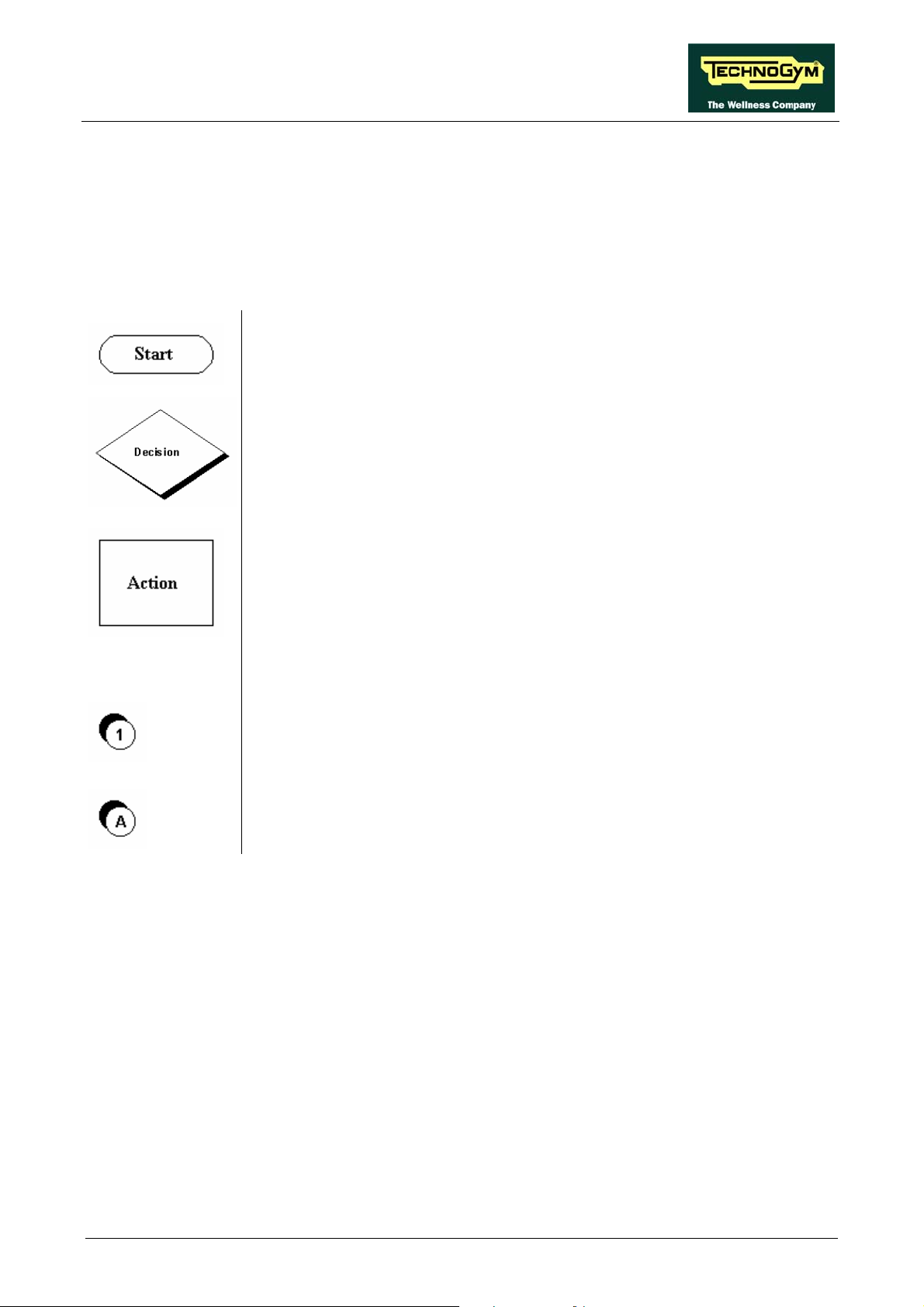
The troubleshooting procedures are shown in the form of flow charts. In order to facilitate
consultation, the following standard box shapes are used.
This type of box is the START point of the troubleshooting procedure. It
typically contains a description of the problem or malfunction.
This type of box represents a decision point in the troubleshooting procedure.
It typically contains a description of the CHECK to be made, with an outcome
that can be either a positive (YES) or negative (NO) response.
This type of box is a step in the troubleshooting procedure where an ACTION
must be carried out. It typically contains a description of the ACTION
necessary to resolve the problem. Therefore, after executing the specified
ACTION:
1. Check whether the problem has been resolved;
2. If the problem persists, it is recommended to resume the troubleshooting
procedure from the point before the action was carried out.
A circled number (such as that shown on the left) next to a box of the
troubleshooting procedure indicates that detailed instructions for performing
that particular check or action are provided below the flowchart.
A circled letter (such as that shown on the left) is used to highlight a point in
the procedure. Typically, this indicator is used in page changes.
Page 6.1
JOG EXCITE: Service & Maintenance Manual - rev. 1.1
6.1. TROUBLESHOOTING SERVICE MENU
This section can be used to test the operation of certain machine components (AC/DC Motors, LED
display, keyboard, serial ports, inverter). It is invoked, when the machine is in standby mode, by
simultaneously pressing the keys ENTER, ↑, CLEAR. The following prompt appears on the LED
display:
ENTER PASSWORD:
To access the procedure, insert the password 2501 which protects against unauthorized access and
press ENTER to confirm. To enter the password without the numeric keypad, enter one digit at a
time using the ↑ and ↓ keys to change the value and the +/- GOAL keys to scroll to the next
character. At this point there are two options available:
↑ = Tech Config
↓ = Troubleshooting
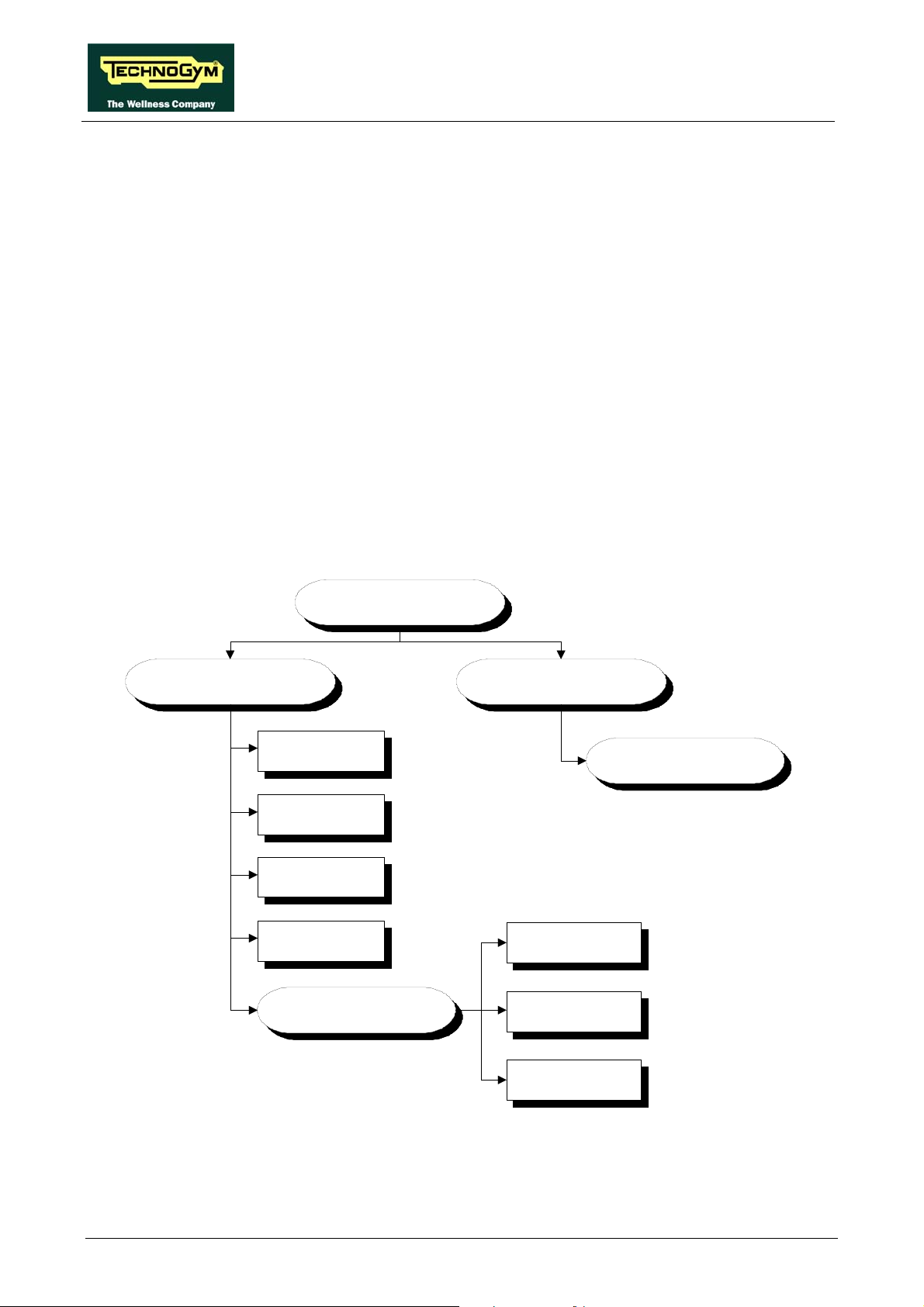
Press the number key 2 to access the troubleshooting menu, which is structured as shown in the
figure below.
TROUBLESHOOTING
AUTOMATIC TEST MANUAL TEST
I2C Devices Test
UpDown Tes t
Inverte r Test
LED Test
SERIAL PORT S
TEST
TGS COM Test
Low Kit COM Test
MAN.KEYBOARD
TEST
CSafe COM Test
To scroll through the list of available functions, press the + or – speed keys to display the next or
previous item. Confirm the choice by pressing ENTER. To cancel the operation, press the CLEAR
key for a few seconds.
Page 6.2

JOG EXCITE: Service & Maintenance Manual - rev. 1.1
The tests are divided into two groups: Automatic and Manual. The machine prompts for a choice
immediately upon accessing the troubleshooting menu.
6.1.1. AUTOMATIC TESTS
The tests grouped under this section conduct checks on the machine’s operation in a fully automatic
manner. After selecting the desired test using the + and – speed keys, press ENTER to initiate the
test and then await the result. Press ENTER again to continue, or press the CLEAR key for a few
seconds to return to the higher menu level. The various tests are described below.
6.1.1.1. I2C Device Test
The I2C Device test checks the communication following the 32K and 256K memories. The test
can have two outcomes:
• “Test Successful, press Enter to continue”: Signifies that data packets were successfully
transmitted and received toward the display board.
• “EEPROM Error, press Enter to continue”: Signifies that the display board has
communication problems with the memories.
6.1.1.2. UpDown Test
The UpDown test checks whether the number of pulses output by the encoder corresponds to the
values of the UpDown table stored in the low kit. During the test, the machine incline is moved
from 0 to 15% and then back to 0. Each incline position is converted into a number of pulses and
compared with the value in the UpDown table.
Two messages appear during the test:
- “Incline =15%”: This message appears during the upward movement, when the machine incline
reaches 15%.
- “Incline =3%”: This message appears during the downward movement, when the machine
incline reaches 3%.
The test can have two outcomes:
• “DC Error (Up/Down), press Enter to continue”: The message indicates that the values do
not correspond. The specific message (Up or Down) indicates whether the error occurred during
the upward (Up) or downward (Down) movement of the test.
• “Test Successful, press Enter to continue”: This message indicates that the test was
completed without errors.
6.1.1.3. Inverter Test
The inverter test checks the condition of the AT driver. The test can have two outcomes:
• “Test Successful, press Enter to continue”: This means that the test was completed
successfully and the inverter is not in an error condition.
• “Inverter Error, press Enter to continue”: This means that the test was not completed
successfully, i.e. that the serial link is inactive and/or the inverter is in an error condition.
Page 6.3

JOG EXCITE: Service & Maintenance Manual - rev. 1.1
6.1.1.4. LED Test
The LED test checks the functioning of the display by lighting all the LEDs in the matrix. It also
tests the buzzer, varying the frequency to produce different tones of sound.
The test does not produce a result message, so the user must visually check the outcome.
6.1.1.5. Serial Ports Test
The serial ports test checks the following communication ports:
• CSafe COM test;
• Low Kit COM test;
• TGS COM test.
Using the + and – speed keys, select the desired test item and confirm by pressing ENTER. The test
can have two outcomes:
• “Test Successful, press Enter to continue”: This means that the test was completed
successfully, i.e. that serial communications on the selected port are correct.
• “COMx Error, press Enter to continue”: This means that the outcome of the test was
negative: the message will specify COM1 in the case of the CSafe COM test, COM2 in the case
of communications with the low kit, or COM3 in the case of the TGS COM test.
NOTE: The communication with the CSafe port and the TGS is not working if any device is not
connected to the port.
6.1.2. MANUAL TEST
This section groups together tests for manually checking the operation of certain peripheral devices.
After selecting the desired test item using the + and – speed keys, press ENTER to access the tests.
To exit test mode, hold down the CLEAR key for a few seconds.
The various manual tests are described below.
6.1.2.1. Man. Keyboard Test
The m
the test by pressing ENTER, the message “Press all buttons (beep=OK)” appears on the display.
Pressing each key will produce an audible signal, if a key does not produce the “beep” it means it is
not working properly.
anual keyboard test checks the functioning of all the keys on the keyboard. After accessing
Page 6.4

JOG EXCITE: Service & Maintenance Manual - rev. 1.1
6.2. THE DISPLAY FAILS TO ILLUMINATE
This error occurs when the power supply voltage does not reach the upper assembly.
THE DISP LAY
FAILS TO
ILLUMINATE
NO
Does t h e wall out let s upply the
correct v oltage?
Plug th e m ac hine i nt o a
working elec tric al out l et
YES
Is t he m ains lead OK?
YES
Is the v oltage at t he
output of the mac hi ne's
power inlet block c orrec t?
YES
Is the voltage at t he input
to t he c i rc uit breakers
correct?
NO
Replace the mains l ead
1
NO
Replace t he power
inlet block on t he
machine
2
NO
Replace cable CU 143
Continued on the following page.
YES
A
Page 6.5

JOG EXCITE: Service & Maintenance Manual - rev. 1.1
A
3
Is the voltage at t he
output of the circ uit
breakers c orr ec t , when
they are pres s ed?
YES
Is the v oltage at t he inpu t
to t h e AT driver box ?
YES
Is the 400VdC v oltage
correct ly suppl ied by the
AT driver board?
NO
Replace t he c i rc ui t
breakers
4
NO
Replace f ilt er board
5
NO
Replace t he AT driv er
board
Is the EAM2068 cable
correc t ( c hec k pin to pin)?
Is the voltage at t he input
to t h e AT drive r board
Continued on the following page.
correct?
B
YES
NO
Replace t he EAM2068
cable
YES
6
NO
Replace the power
supply board
YES
Page 6.6

JOG EXCITE: Service & Maintenance Manual - rev. 1.1
Are the DC voltages at the
output of the AT driver
board cor rec t?
YES
Replace t he display
board
Are the DC voltages at the
input t o t he d is pl ay board
B
7
NO
Replace t he AT driv er
board
YES
8
NO
Replace cable CU 133
correct?
Follow the procedure step by step to correctly diagnose the problem. Take particular care with the
checks highlighted by circled numbers, which are described in detail below:
To speed up the troubleshooting procedure, check the state of the power indicator LEDs
on the various circuit boards.
(1) Slightly lift the Faston connectors on the machine power inlet socket. Place the tester probes
across the live and neutral pins on the same connector. The measured voltage should be
approximately 220 VAC.
(2) As for step (1) but across the input of the circuit breakers.
(3) As for step (1) but across the output of the circuit breakers.
(4) Unplug the cable coming from the filter board, from the connector J1 on the AT driver board.
Place the tester probes on the same connector. The measured voltage should be approximately
220 VAC.
(5) Check that the red LED H5, on the AT driver board is on.
(6) Using a tester, check the voltages on the back of connector XU2 on the AT drive board,
placing the probes on test points 1-2 to measure the +12 Vdc signal (see figure below).
Page 6.7

JOG EXCITE: Service & Maintenance Manual - rev. 1.1
(7) Using a tester, check that the output voltage +12 Vdc on connectors J3 of the AT driver board
are correct, by referring to paragraph 2.7. “Wiring”.
(8) As for step (7) but on connector CN7 of the display board.
Page 6.8

JOG EXCITE: Service & Maintenance Manual - rev. 1.1
6.3. “PRESS A KEY” MESSAGE ON THE DISPLAY
This error message may appear when:
• loss of communication between the lower and upper assemblies;
• the user has pressed the emergency button;
• the emergency button is defective and has transiently opened the contact.
In order to reinstate normal operation, simply press any key. If communication between the upper
and lower assemblies is not immediately re-established, the message will remain on the display
while the machine continues trying for 30 seconds, after which the “THE EQUIPMENT IS
BLOCKED” message will appear.
The machine keeps count of the attempts to reinstate communication by incrementing the
COM.FAULT parameter, which can be viewed using the procedure described in paragraph 9.2.4.3
“COM.Fault”.
Page 6.9

JOG EXCITE: Service & Maintenance Manual - rev. 1.1
6.4. “THE EQUIPMENT IS BLOCKED” MESSAGE ON THE
DISPLAY
This error message can be caused by:
• loss of communication between the lower and upper assemblies;
• the AT driver has detected an error condition, causing it to generate an alarm and store the error
code in memory.
• problem on the emergency button.
To optimize the troubleshooting procedure, follow the steps below:
1. Access the item “TROUBLESHOOTINGÆAUTOMATIC TESTÆ SERIAL PORTS
TESTÆLow Kit COM Test”. If the outcome of the test is negative, check the components of
the link between the upper and lower kit, in particular:
• check that the wiring of the cable (CU133) is not damaged, in particular the cables of the
“emergency signal” and of the “reset” by referring to paragraph 2.7. “Wiring”, using the
Test Box Excite.
• try replacing each of the circuit boards in turn (display board or AT driver board) and check
whether the communication works.
If the outcome of the test is OK move on to step 2.
2. Access the item “TROUBLESHOOTINGÆAUTOMATIC TESTÆInverter Test”. If the
outcome of the test is negative, check the error code stored in the “ERRORS LOG” and
perform the corresponding troubleshooting procedure, if the outcome is OK advance to step 3.
3. The machine lockout problem has to do with the handling of the emergency signal:
• check that the emergency button is not pressed;
• check that the cord, linked to the emergency button, is not to taut so that it keep the
emergency button contact open;
• check that all the cables linked to the emergency device management are properly connected
and in a good state of wear.
WARNING: if the display board detects an error condition during the tread belt motor
movement, it displays the error message and turns off the AC motor by the AT driver.
Page 6.10

JOG EXCITE: Service & Maintenance Manual - rev. 1.1
6.5. AT DRIVER ERROR
When the AT driver detects an error, it stops and interrupts the power supply to the tread belt and
elevation motor. An error code identifying the fault condition is saved in the error history log. In
addition, it sends an error status signal to the display board via the serial link. Upon receiving this
error signal, the display board halts the exercise and shows the “THE EQUIPMENT IS
BLOCKED” message on the display.
The errors logged by the inverter can also be viewed as described in paragraph 9.2.4. “Errors log”.
The following table shows the correspondence between the numbers and codes:
Error
code
OH 1 Overheating of the heat sinks of the AT drive and of the PFC.
OC 2 Overcurrent, even if only transient, on the inverter output.
UU 3 Undervoltage condition, due to an even transient drop in line voltage.
OU 4 Overvoltage.
PE 6
EdC1 7 Elevation motor encoder error.
OtM 9 AC motor thermal cutout open.
Oli 10
OLm 11
OLr 12 Braking resistor overload.
Ot 13
OCH 16 HW overcurrent.
MST 17
EM 19
SHC 23
Error
number
Description
EEPROM error. Is generated when there is an error detected in the data
stored on the EEprom.
Inverter overload caused by a DC current exceeding, for the maximum
allowed time (I2t), the maximum permissible threshold for the inverter.
Motor overload caused by a DC current exceeding, for the maximum
allowed time (I2t), the maximum permissible threshold for the motor in
question.
Over-torque due to an even momentary overload of the inverter. Is
generated when the torque output of the motor exceeds a pre-established
limit for a pre-established time.
Motor lockout which occurs, operating in closed loop mode with the
encoder active, if the inverter fails to reach the target speed even after
attempting to reduce the reference frequency.
Emergency. Is generated when the AT drive receives a software
emergency signal that is not accompanied by a hardware emergency
signal.
Short Circuit. Is generated in the event of a short circuit between a motor
phase and earth.
Page 6.11

JOG EXCITE: Service & Maintenance Manual - rev. 1.1
TH E A T DR IVER HA S
DETECTED AN ERROR
Check t he error c ode
st or ed in m em or y
OH
OC - OLi - OL m - Ot - MST - OCH - S HC
UU
OU
Carry out the "GRADIENT
EdC1
NOT WORKING"
troubl es hooting procedure
OtM
OLr
PE
Carry out the
EM
"SW EMERGENC Y"
troubl es hooting procedure
The following paragraphs describe the troubleshooting procedures for these three cases.
Page 6.12
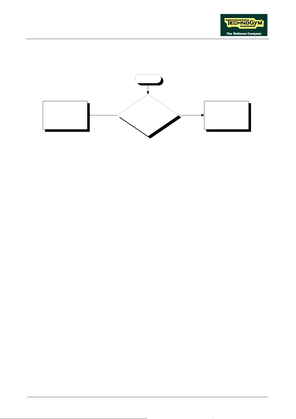
JOG EXCITE: Service & Maintenance Manual - rev. 1.1
6.5.1. ERROR OH
This error indicates overheating of the heat sink on the AT driver board.
OH
Replace the AT driver
board
NO
Does t he m ac hine res um e
correc t operation after being
switc hed off f or 1 hour?
YES
Probable overheating of the
AT driv er. The mac hine is
OK
Page 6.13

JOG EXCITE: Service & Maintenance Manual - rev. 1.1
6.5.2. ERRORS OC - OLI - OLM - OT - OCH - MST - SHC
These errors are associated with overcurrent or overloading of the inverter and/or motor.
OLi OLM OT OCHOC
Are the runni ng deck table and
tread be lt i n good c ondi t ion and
well lubric at ed?
NO
MST SHC
Change the t abl e and t r ead
belt and/ or lubricate
YES
Does t h e problem on ly occ ur
with users who are too heavy ?
YES
Do not exc eed t he
maximum weight limit (180
kg - 397 lbs )
NO
Are the bearings of the rollers
in good condition?
Replace the rollers
YES
1
NO
YES
Replace the AT driver
board
Replace the t read belt
motor
NO
Are the AT driver out put s ,
short-circuited?
Follow the procedure step by step to correctly diagnose the problem. Take particular care with the
checks highlighted by circled numbers, which are described in detail below:
(1) Disconnect the motor cable from the AT driver box and place the tester probes across its
terminals U-V, U-W and V-W. The measured resistance should be very high, in the order
Mohms. Disconnect the motor cable from the AT driver box and place the tester probes
across its terminals U-ground, V-ground and W-ground. The measured resistance value
should be that of an open contact.
Page 6.14
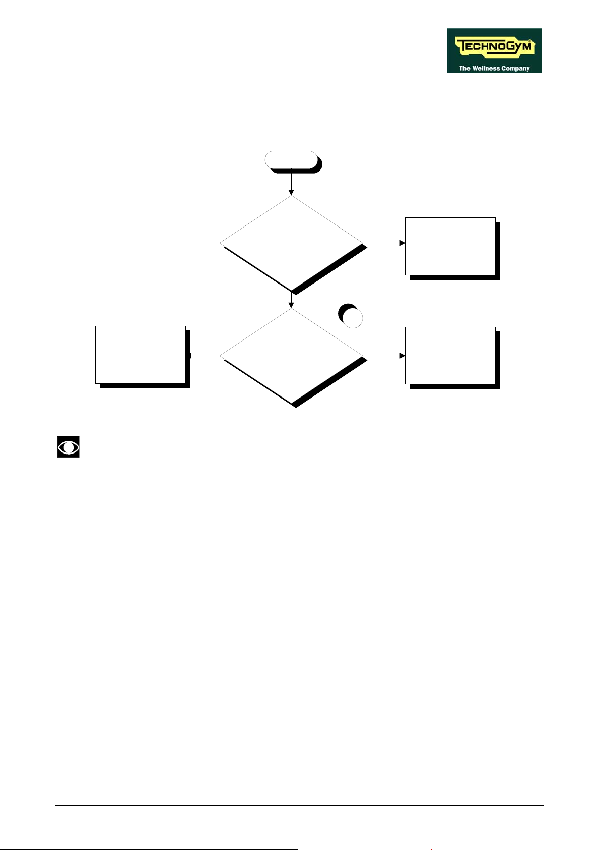
JOG EXCITE: Service & Maintenance Manual - rev. 1.1
6.5.3. ERROR UU
This error indicates low voltage problems on the AT driver supply line.
UU
YES
Probable low line v olt age.
The machine i s OK
1
YES
Replace the AT driver
board
Correct t he caus e of the
exces s ively low line v olt age
NO
Does the mac hi ne res um e
correct oper at ion af ter being
switched of f f or 1 mi nute?
NO
Is t he s upply v olt age at t he
input to the AT driver correct?
This error can be generated by even transient glitches in the mains supply due to
overloading or other factors. Therefore it can be useful to check, in the inverter error
log, the value of mains voltage recorded at the time when the error occurred.
Follow the procedure step by step to correctly diagnose the problem. Take particular care with the
checks highlighted by circled numbers, which are described in detail below:
(1) Place the tester probes across terminals of the connector J1 of the AT driver board. The
measured voltage should be 220 VAC.
Page 6.15

JOG EXCITE: Service & Maintenance Manual - rev. 1.1
6.5.4. ERROR OU
This inverter error message indicates an overvoltage condition on the inverter supply line.
OU
Does the mac hi ne res um e
correct oper at ion af ter being
switched of f f or 1 mi nute?
YES
Probable high line v oltage.
The machine i s OK
NO
1
Correct t he caus e of the
exc es s iv ely high line
voltage
NO
Is t he s upply v olt age at t he
input to the AT driv er box
correct?
YES
Replace the AT driver
board
This error can be generated by even transient spikes in the mains voltage, resulting from
overloading or other factors. Therefore, it can be useful to check, in the error log, the
value of the mains voltage recorded at the time when the error occurred.
Follow the procedure step by step to correctly diagnose the problem. Take particular care with the
checks highlighted by circled numbers, which are described in detail below:
(1) Place the tester probes across terminals of the connector J1 of the AT driver board. The
measured voltage should be 220 VAC.
Page 6.16

JOG EXCITE: Service & Maintenance Manual - rev. 1.1
6.5.5. ERROR OTM
This error indicates that the thermal cutouts of the tread belt motor have been tripped.
OtM
Does t h e m ac hin e res um e
correc t operation after being
switched of f f or 1 hour?
Probable overheating of the
motor. The machine is OK
NO
1
YES
NO
Replace the t read belt
motor
Replace the AT driver
board
YES
Are the motor thermal cutout
signal c orr ec t at t he in put of the
AT driv er board?
Follow the procedure step by step to correctly diagnose the problem. Take particular care with the
checks highlighted by circled numbers, which are described in detail below:
(1) Disconnect the cable TRM-06 and place the tester probes across pins 4 and 5 of its connector.
The measured value of the resistance should be less than 1 Ohm.
This value may be higher as a result of oxidation of the contacts. To reinstate correct
operation it is necessary to perform a special procedure that will be communicated to
you on contacting the Technogym Support Service.
Page 6.17
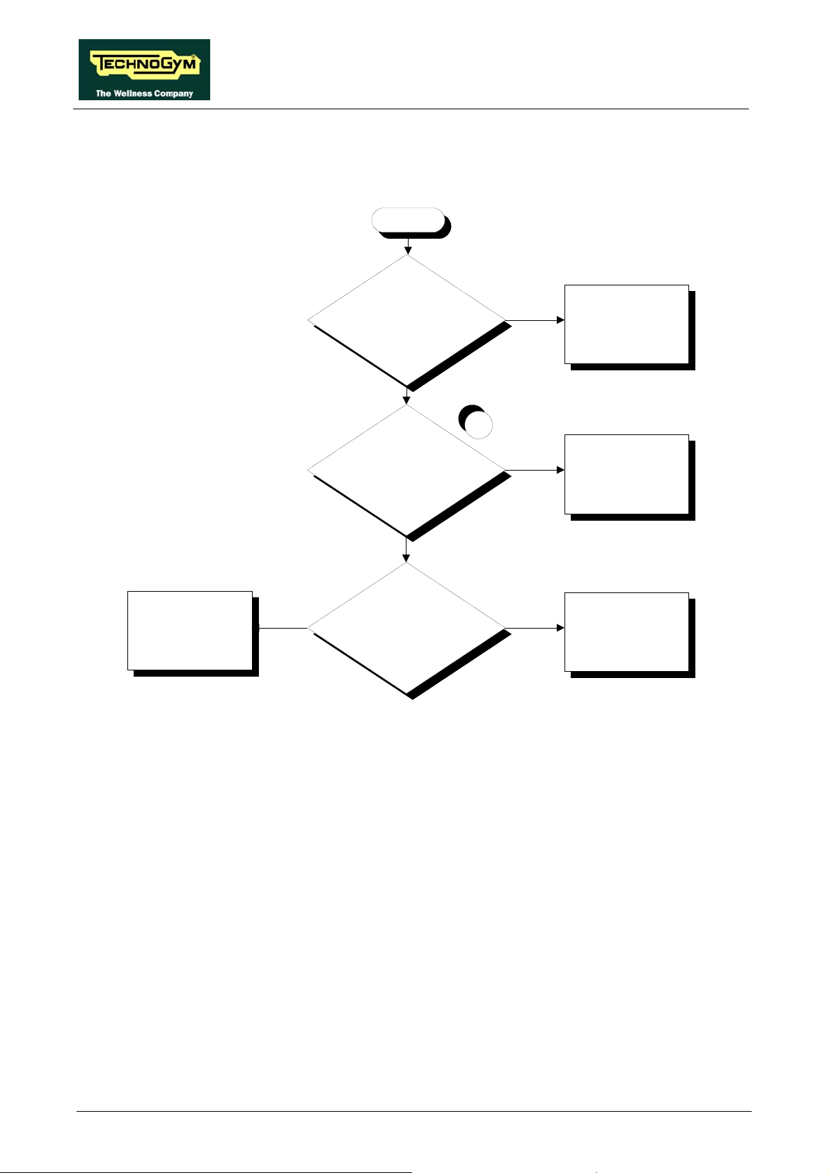
JOG EXCITE: Service & Maintenance Manual - rev. 1.1
6.5.6. ERROR OLR
This error indicate problem with the braking resistor.
OLr
Replace the AT driver
board
NO
Is the brak i ng res i s t or c orre c t l y
connected to t he AT driver
board?
YES
Is the v alue of t h e brak i ng
resistance correct?
YES
Does the mac hi ne res ume
correct oper at ion af ter bein g
switc hed off f or 1 minute?
NO
Reinstat e t he connect i on
1
NO
Replace the braking
resistor
YES
Possibl e dis t urbanc e. The
machine is OK
Follow the procedure step by step to correctly diagnose the problem. Take particular care with the
checks highlighted by circled numbers, which are described in detail below:
(1) With the machine switched off, disconnect the fastons of the resistor from the AT driver
board and place the tester probe across them. The measured value of the resistance should be
150 Ohm.
Page 6.18

JOG EXCITE: Service & Maintenance Manual - rev. 1.1
6.5.7. ERROR PE
This error indicate problem on the data of the Eeprom.
PE
1
Does the error oc c ur
frequently?
NO
Does the mac hi ne res ume
correct oper at ion af ter being
turned of f f or 1 mi nute?
NO
Re-program the AT driver
YES
Replace the AT driver
board
YES
Probable int er f erence. The
machine is OK
2
Replace the AT driver
board
NO
Does the mac hi ne res ume
correct oper at ion af ter being
turned off for 10 minutes?
YES
Programming c orrec t . The
machine is OK
Follow the procedure step by step to correctly diagnose the problem. Take particular care with the
checks highlighted by circled numbers, which are described in detail below:
(1) Determine the frequency of the errors by counting the number of occurrences and by running
targeted checks. An error is considered frequent if it occurs 2 or 3 times a day.
(2) Re-program the AT driver following the procedure described in paragraph 9.5. “Default
parameters”.
Page 6.19

JOG EXCITE: Service & Maintenance Manual - rev. 1.1
6.5.8. ERROR EM
The error is generated if the AT drive receives a software emergency signal via the 485 serial
communications link between the upper and lower assemblies, but does not receive the
corresponding emergency hardware signal via cables TRM-19 and TRM-20.
EM
1
YES
YES
Replace the AT driver
board
Probable interf erence. The
machine is OK
Replace the AT driver
board
NO
Does t h e error occ ur
frequently?
NO
Does t h e m ac hine r es um e
correc t operat i on af ter being
turned of f f or 1 mi nute?
Follow the procedure step by step to correctly diagnose the problem. Take particular care with the
checks highlighted by circled numbers, which are described in detail below:
(1) Determine the frequency of the errors by counting the number of occurrences and by running
targeted checks. An error is considered frequent if it occurs 2 or 3 times a day.
Page 6.20

JOG EXCITE: Service & Maintenance Manual - rev. 1.1
6.6. TREAD BELT MOTOR IS JERKING
The probable cause is:
• a disconnected phase either at the AT driver board output or on the motor;
TREAD BELT
MOTOR IS
JERKING
1
NO
Replace t he t r ead belt
motor
Replace t he AT driv er
YES
Are the tread bel t m ot or
windings resis tanc e correct ?
Follow the procedure step by step to correctly diagnose the problem. Take particular care with the
checks highlighted by circled numbers, which are described in detail below:
(1) Disconnect the cable from the motor and place a tester across its terminals U-V, U-W and V-
W. The measured value of the resistance should be 1.9 Ohm.
Page 6.21

JOG EXCITE: Service & Maintenance Manual - rev. 1.1
6.7. “GRADIENT NOT WORKING” MESSAGE ON THE
DISPLAY
If the elevation does not work and there is no error message on the display, the elevation
movement may have been disabled in the configuration menu. For further details, refer
to paragraph 9.1.14. “Enable up/down motor”.
Check parameter PAR 09 is 15.
This parameter defines the time window within which the inverter expects to receive a
sufficient number of pulses from the elevation motor, before generating an error
condition.
1. This error message indicates that the machine is unable to control the elevation motor. The error
is produced when the inverter does not receive pulses from the motor encoder, after having
enabled it. In this case the machine disables any movement and sets the parameter PAR 07 to 1.
2. The error message may be caused by a problem with the lower limit switch. In fact if the limit
switch malfunctions or accidentally remains in the open-contact state, rather than in the
normally closed state, the error is not generated immediately but will occur as soon as the
elevation is increased beyond 1%. At this point, the elevation function will be locked out and
parameter PAR 07 set to 1.
3. The error message may be due to a misalignment of the elevation motor encoder. In fact, if the
encoder of the elevation motor is not correctly positioned, the motor will fail to produce a pulse.
At this point, the elevation function will be locked out and parameter PAR 07 set to 1.
When the machine is switched on again, the parameter PAR 07 is automatically reset to 0 and the
machine performs the reset procedure. If the error does not happen anymore, supposing it was
generated by a noise, the machine restarts to work properly.
It might also be helpful to refer to the theoretical explanation of the elevation control,
provided in paragraph 3.3. “Elevation motor drive”.
Page 6.22

JOG EXCITE: Service & Maintenance Manual - rev. 1.1
"GRADIENT NO T
W ORKING " M ESS AGE
ON THE DISPLAY
Check t he P09
parameter is c orrect ly
1
setted
2
Does the s up ply voltage
correc t l y reach connec t or J 7 on
the AT driver board?
NO
Replace the AT driver
board
YES
3
Replace t he AT driv er
board
YES
Do t he pul s es re ac h c onn ec t or
J7 on the AT driv er board?
NO
Replace the elevation
motor
Follow the procedure step by step to correctly diagnose the problem. Take particular care with the
checks highlighted by circled numbers, which are described in detail below:
(1) Check the parameter setting as detailed in paragraph 9.2.1.4 “Table of configuration
parameters”.
(2) Place the tester probes across pins 1 and 2 of connector J7 on the AT driver board. The
measured value should be approximately 24 Vdc.
(3) Place the tester probes across pins 6 and 4 of connector J7 on the AT driver board. The
measured value should be approximately 2.5 Vdc. If an oscilloscope is available, it is possible
to view the pulses produced by the encoder itself.
Page 6.23

JOG EXCITE: Service & Maintenance Manual - rev. 1.1
6.8. THE MACHINE DOES NOT READ THE TGS
The machine displays this error if the TGS reader is not working properly, or if it is not supplied by
the display board.
TH E MAC H INE DOES
NOT READ THE TGS
1
Replace the dis play board
NO
Does t he s upply volt age
correct ly reach the input t o the
TGS reader?
NO
Is the s upply voltage c or rec t at
the output t o the display board?
A
Is the s eri al c om m uni c ation li nk
between t he di s pl ay board and
the TGS reader OK?
YES
A
2
YES
Replace c able C BQ- 32
3
YES
Replace the TGS reader
NO
3
Replace t he display board
NO
Replace the TGS reader. Is the
com m uni cat ion l in k between the
display board and the TGS
reader OK?
YES
TGS reader defec tive
Follow the procedure step by step to correctly diagnose the problem. Take particular care with the
checks highlighted by circled numbers, which are described in detail below:
Page 6.24

JOG EXCITE: Service & Maintenance Manual - rev. 1.1
(1) Place the tester probes across pins 1 and 3 of connector CN1 of the TGS reader. The
measured value should be +12 Vdc.
(2) As for step (1) but across pins 1 and 9 of connector CN3 on the display board.
(3) Use the serial communications test described in paragraph 6.1.1.5 “Serial Ports Test”.
Page 6.25

JOG EXCITE: Service & Maintenance Manual - rev. 1.1
6.9. THERE IS NO HEART RATE SIGNAL
6.9.1. TELEMETRIC RECEIVER HFU
The machine displays this error if:
1. electromagnetic noise saturate the HR receiver which does not display any value due to a
specific SW filter which cut every signal, greater than 220 bpm;
2. the receiver is not working properly;
3. the receiver is not supplied by the display board.
TH ER E IS NO HR
SIGNAL
1
Carry out the
troubl es hooting pr oc edure
"THE TELEMETRIC
SIGN AL I S IN C OR R EC T"
2
Replace the dis play board
NO
Does t he s upply volt age
correct ly reach the input t o the
receiver?
NO
Is the s upply voltage c or rec t at
the out put of the display board?
YES
Replace the rec eiv er
3
YES
Replace cable CU 135
Follow the procedure step by step to correctly diagnose the problem. Take particular care with the
checks highlighted by circled numbers, which are described in detail below:
(1) Carry out the troubleshooting procedure 6.10. “The telemetric hr signal is incorrect”.
(2) Place the tester probes across pins 1 and 2 of connector HD4 of the HS / cardio receiver
board. The measured value should be +5 Vdc.
(3) As for step (2) but across pins 1 and 5 of connector CN9 on the display board.
Page 6.26

JOG EXCITE: Service & Maintenance Manual - rev. 1.1
6.9.2. HAND SENSOR
The machine displays this error if the HS / cardio receiver board is not working, or if it is not
supplied by the display board.
TH ER E IS NO HR
SIGNAL
1
Check t he eart h c onnec tion
of t he m ac hi ne
2
Replace the dis play board
NO
Are the sens ors correct ly
connected to t he H S/ c ardio
receiv er board?
YES
Is the s upply voltage c or rec t at
the in put t o t he H S/c ardi o
receiv er board?
NO
Is the s upply voltage c or rec t at
the out put of the HS/ c ardio
receiv er board?
NO
Reinstat e t he connect i on
3
YES
Replace the HS/cardio
recei v er board
4
YES
Replace cable CU 135
Follow the procedure step by step to correctly diagnose the problem. Take particular care with the
checks highlighted by circled numbers, which are described in detail below:
(1) Check the earthing of the machine using a tester to measure the resistance between the ground
pin on the power supply cable and the ground node to which the hand sensor are connected
inside the display. The value must be less than 1 Ohm.
(2) Check the connections, referring to paragraph 2.7. “Wiring”.
Page 6.27

JOG EXCITE: Service & Maintenance Manual - rev. 1.1
(3) Place the tester probes across pins 2 and 1 of connector HD4 on the HS/cardio receiver board.
The measured value should be +5 Vdc.
(4) As for step (2) but across pins 1 and 5 of connector CN9 on the display board.
Page 6.28

JOG EXCITE: Service & Maintenance Manual - rev. 1.1
6.10. THE TELEMETRIC HR SIGNAL IS INCORRECT
The machine displays this error if the receiver is disturbed by sources of electromagnetic noise.
THE TELEMETRIC
HR SIG N AL IS
INCORRECT
1
Check t he eart h c onnec tion
of t he m ac hi ne
2
Are the m achines c orrec tly
spac ed by the r equire d m inim u m
distance?
YES
Is the
HS/cardio rec eiv er board
correc t l y positioned and are t he
connect ing c abl es proper ly
routed?
YES
Are there s ourc es of
electrom agnetic noi s e near t he
HS/ cardio r ec ei v er board?
NO
Reposition t he mac hines
so t hey are adequately
spaced
3
Correct t he po s ition of the
NO
HS/ cardio r ec ei v er board
and the ro ut ing of the
cables
4
YES
Move the mac hi ne away
from the noise s ource or
att enuat e t he power of t he
noise
Continued on the following page.
NO
A
Page 6.29

JOG EXCITE: Service & Maintenance Manual - rev. 1.1
A
5
NO
Is the t ransm it ter in go od
working order?
YES
Us e a c orr ec t l y
func t i oning t rans m itt er
Replace the HS/cardio
recei v er board
YES
Is the transmitter always within
the 80 cm range f rom t h e
HS/ cardi o recei v e
NO
Reposition the transmitter
withi n r an g e
Follow the procedure step by step to correctly diagnose the problem. Take particular care with the
checks highlighted by circled numbers, which are described in detail below:
(1) Check the earthing of the machine using a tester to measure the resistance between the ground
pin on the power supply cable and the ground node to which the receiver is connected inside
the display. The value must be less than 1 Ohm.
(2) In the table below , the minimum distances at which machines should be installed to avoid
crosstalk problems.
R
U
N
R
U
N
2
RUN
2
RUN
2
2
DISTANCE CASING-CASING
machine 2 machine 2 machine 2 machine 2
Bike Recline Run Bike Recline Run Bike Recline Run Bike Recline Run
10 20 10 50 50 40 10 10 10 10 40 10
DISTANCE RECEIVER-RECEIVER
machine 2 machine 2 machine 2 machine 2
Bike Recline Run Bike Recline Run Bike Recline Run Bike Recline Run
195 205 230 115 115 130 130 130 170 225 285 300
Page 6.30

JOG EXCITE: Service & Maintenance Manual - rev. 1.1
r
For machine positioning layouts different from those indicated above, use the following
diagram as a reference.
89
60
99
78
99
77
102
70
Receiver
115
86
103
83
95
76
103
82
where:
1. The distances are in centimeters.
2. The smaller number indicates the maximum locking distance for signal reception at the
start of the exercise.
3. The higher number indicates the maximum reception distance during the exercise.
(3) Check that the cardio receiver has been assembled properly as described in the procedure 7.5.
“Disassembling the cardio receiver”.
(4) To check for electromagnetic noise near the machine, use Test Box Excite as detailed here
below. You can use one of the following cables ELT-16 (0WC00518AB), CBQ-28
(0WC00390AC) or TRM-28 (0WC00336AC) as connection cable.
HFU
Receiver
Connection
cable
HR receive
TEST BOX
EXCITE
The circuit lights the LED for each heart beat and/or disturbance received: in this way it is
possible to determine whether there is any interference, and identify its sources.
(5) Check the battery power level, using a tester if possible. Otherwise use a receiver or another
“reference” machine to check the operation up to a distance of about 80 cm from the receiver.
Page 6.31

JOG EXCITE: Service & Maintenance Manual - rev. 1.1
Page intentionally left blank
Page 6.32

JOG EXCITE: Service & Maintenance Manual - rev. 1.1
7. DISASSEMBLY OF COMPONENTS
7.1. DISASSEMBLING THE DISPLAY
1. Turn off the machine and unplug the mains
lead from the wall outlet.
2. Back off the 2 screws a using a medium
Phillips screwdriver.
Figure 7.1-1
Figure 7.1-2
3. Open the display, leaving it attached to the
machine as shown in the figure.
To remove the display:
4. Disconnect the connectors indicated.
5. Remove the display.
To reassemble the display, carry out the above
steps in reverse order.
Page 7.1

JOG EXCITE: Service & Maintenance Manual - rev. 1.1
7.2. DISASSEMBLING THE CIRCUIT BOARDS OF THE
DISPLAY
Carry out the procedure described in paragraph
7.1. “Disassembling the display”.
Figure 7.2-1
1. Place the display on a work bench.
2. Unplug the connector indicated in the figure.
3. Back off the 5 screws a using a small Phillips
screwdriver.
4. Remove the circuit board.
To reassemble the circuit boards, carry out the
above steps in reverse order.
After the reassembling of the board,
remember to fix the keyboard connector
using a drop of hot glue.
Page 7.2

JOG EXCITE: Service & Maintenance Manual - rev. 1.1
7.3. DISASSEMBLING THE KEYBOARD
Carry out the procedure described in paragraph
7.1. “Disassembling the display”.
1. Unplug connector from
Figure 7.3-1
With the display placed on a work bench:
2. Use a sharp tool to lift up and detach a corner
of the keyboard.
To assemble a new keyboard, with the display on
a work bench:
1. Remove the backing film which protects the
adhesive.
2. Apply the adhesive part, starting from the
left and working toward the right, without
bending the keyboard.
3. Insert the connector in the special slot on the
display and connect it to the display board.
4. Remove the protective film.
the keyboard.
Figure 7.3-2
When reassembling the keyboard, make
sure that none of the keys are bent or
remain pushed in.
After the reassembling of the board,
remember to fix the keyboard connector
using a drop of hot glue.
The keyboard assembly procedure can
only be carried out once, because
disassembly damages the tracks and
keys.
Page 7.3

JOG EXCITE: Service & Maintenance Manual - rev. 1.1
7.4. DISASSEMBLING THE EMERGENCY BUTTON
Carry out the procedure described in paragraph
7.1. “Disassembling the display”.
1. Back off the 8 screws a using a medium
Philips screwdriver.
2. Remove the front display casing and place it
on a work bench.
Figure 7.4-1
3. Disconnect the cable b from the two faston
connectors on the emergency button.
4. Back off the 4 screws c using a small Philips
screwdriver.
5. Remove the emergency button from the front
side.
6. Back off the 2 screws d using a medium
Philips screwdriver and remove the two
microswitch.
To reassemble the emergency button, carry out
the above steps in reverse order.
Figure 7.4-2
Page 7.4

JOG EXCITE: Service & Maintenance Manual - rev. 1.1
7.5. DISASSEMBLING THE CARDIO RECEIVER/HAND
SENSOR BOARD
Carry out the procedure described in paragraph
7.1. “Disassembling the display”.
1. Back off the 8 screws a using a medium
Philips screwdriver.
2. Remove the front display casing.
Figure 7.5-1
Figure 7.5-2
3. Cut the cable tie and remove the
Receiver/hand sensor board from the nylon
bag.
To assemble the new receiver:
1. Connect the cable to the board and bend the
cables on the rear side of the board.
Figure 7.5-3
Continued on following page →
Page 7.5

JOG EXCITE: Service & Maintenance Manual - rev. 1.1
2. Place the board on the sponge taking care
that the coil is upward.
Figure 7.5-4
Figure 7.5-5
3. Fold the sponge on the board as shown in the
picture.
4. Secure the sponge on the board with some
tape or with a cable tie. Make sure it is
secured but not too fasten.
5. Encase the board in a plastic bag.
6. Close and secure the plastic bag with some
tape on the cable as indicated in the figure.
the receiving coil must be oriented
upwards and toward the user (as shown
in the figure to side).
Page 7.6
Figure 7.5-6

JOG EXCITE: Service & Maintenance Manual - rev. 1.1
7.6. DISASSEMBLING THE SENSORS
1. Turn off the machine and unplug the mains
lead from the wall outlet.
For each sensor:
2. Back off the 2 screws a using a small Phillips
screwdriver.
Figure 7.6-1
3. Lift up the top sensor.
4. Remove the lower sensor.
5. To disconnect the sensors, unplug the two
fastons b.
To reassemble the sensors, carry out the above
steps in reverse order.
Figure 7.6-2
Page 7.7

JOG EXCITE: Service & Maintenance Manual - rev. 1.1
7.7. DISASSEMBLING THE READY TO RUN BOARD
1. Turn off the machine and unplug the mains
lead from the wall outlet.
2. Back off the screw a using a small Phillips
screwdriver.
3. Remove the plastic cover b from the
handlebar.
Figure 7.7-1
4. Disconnect the connector c from the board.
5. Remove the board from the plastic cover.
To reassemble the board, carry out the above
steps in reverse order.
During the reassembling procedure do
not forget to place again the light
conveyor “d” between the board and the
Figure 7.7-2
cover.
Page 7.8

JOG EXCITE: Service & Maintenance Manual - rev. 1.1
7.8. SMONTAGGIO MANIGLIONI
Carry out the procedure described in paragraph
7.1. “Disassembling the display”.
1. Back off the 2 screws a using a m
2. Remove the handlebar pulling it out from the
Figure 7.8-1
edium
Phillips screwdriver.
rear side.
Figure 7.8-2
To disassemble the central handlebar:
3. Carry out the procedure described in
paragraph 7.1. “Disassembling the display”.
4. Back off the 8 screws b using a medium
Phillips screwdriver.
5.
6. Back off the 2 screws c using a 6-mm hex
wrench.
7. Remove the handlebar taking care of the
cable coming from the hand sensor.
To reassemble the handlebars, carry out the
above steps in reverse order.
Figure 7.8-3
Page 7.9

JOG EXCITE: Service & Maintenance Manual - rev. 1.1
7.9. DISASSEMBLING THE MOTOR GUARD
Figure 7.9-1
Turn off the machine and unplug the mains lead
from the wall outlet.
1. If possible, lift up the machine at the
elevation of 10%, to make the procedure
easier.
2. Back off the 6 screws a, using a 4-mm hex
wrench.
3. Remove the motor casing pulling it out from
the front side of the machine.
To reassemble the motor guard, carry out the
above steps in reverse order.
Page 7.10

JOG EXCITE: Service & Maintenance Manual - rev. 1.1
7.10. DISASSEMBLING THE MOTOR COMPARTMENT FAN
Carry out the procedure described in paragraph
7.9. “Disassembling the motor guard”.
1. Disconnect from
connectors a indicated in the figure, of the
fan and of the limit switch.
Figure 7.10-1
the AT driver the 2
Figure 7.10-2
2. Turn the machine over on one side.
3. Back off the 7 screws b using a 4-mm hex
wrench.
4. Remove the lower casing plate.
5. Back off the 4 screws c using a medium
Phillips screwdriver.
6. Remove the fan from the lower casing plate.
To reassemble the fan, carry out the above steps
in reverse order.
Remember to connect again the limit
switch cable.
Figure 7.10-3
Page 7.11
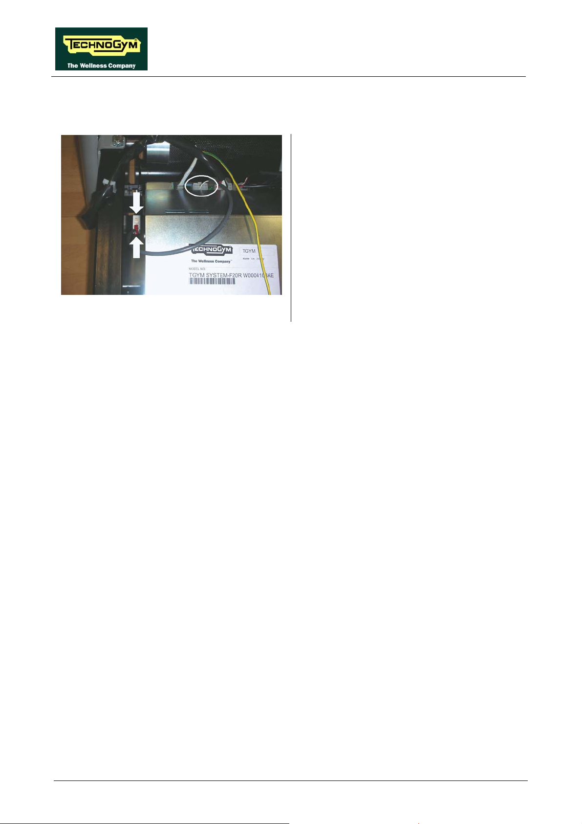
JOG EXCITE: Service & Maintenance Manual - rev. 1.1
7.11. DISASSEMBLING THE LIMIT SWITCH
Carry out the procedure described in paragraph
7.9. “Disassembling the motor guard”.
1. Disconnect the connector of the limit switch
cable from the AT driver.
2. Press on both the sides of the limit switch
and pull it out from the lower side of the
machine.
To reassemble the limit switch, carry out the
above steps in reverse order.
Figure 7.11-1
Page 7.12

JOG EXCITE: Service & Maintenance Manual - rev. 1.1
7.12. DISASSEMBLING THE ELECTRICAL BOX
Carry out the procedure described in paragraph
7.9. “Disassembling the motor guard”.
Figure 7.12-1
1. Back off the screws a using a medium
Phillips screwdriver.
2. Disconnect the cables entering the electrical
box:
• Power supply cable from the power
supply box;
• Cable connecting upper and lower
assemblies;
• Limit switch cable;
• Ground connection cable;
• Fan cable;
• Tread belt motor cable;
• Elevation motor cable (TRM-08).
3. Remove the entire box from its compartment
in the machine.
To reassemble the electrical box, carry out the
above steps in reverse order.
Page 7.13

JOG EXCITE: Service & Maintenance Manual - rev. 1.1
7.13. DISASSEMBLING THE ELECTRONICS BOARDS
Carry out the procedure described in paragraph
7.12. “Disassembling the electrical box”.
1. Back off the 4 screws a using a medium
Phillips screwdriver.
2. Lift up the cover.
Figure 7.13-1
Figure 7.13-2
1. Unplug the fan cable from the AT driver
board.
2. Unscrew the two screws b using a medium
Phillips screwdriver.
3. Remove the fan.
AT driver board:
1. Unplug the flat cable coming from the AT
power supply board, shown in the picture.
2. Unscrew the screw c using a medium Phillips
screwdriver.
3. Lift up the board paying attention to the
cables connected on the lower side.
Page 7.14
Figure 7.13-3
Continued on following page →

JOG EXCITE: Service & Maintenance Manual - rev. 1.1
Figure 7.13-4
4. Unplug the two cables d coming from the AT
power supply board.
5. Unplug the faston e of the two cables coming
from the resistance.
6. Remove the AT driver board.
Figure 7.13-5
Figure 7.13-6
Resistance:
1. Unscrew the two screw f using a Phillips
screwdriver.
2. Remove the resistance.
AT power supply board:
1. Unplug the cable coming from the fan g and
disassembling the fan.
2. Unscrew the screws h using a Phillips
screwdriver.
3. Unscrew the spacers i using a 7-mm wrench.
4. Remove the board, detaching the adhesive
tape which fix the bracket, indicated by the
arrow on the box metal casing.
To reassemble the electronics boards, carry out
the above steps in reverse order.
Page 7.15
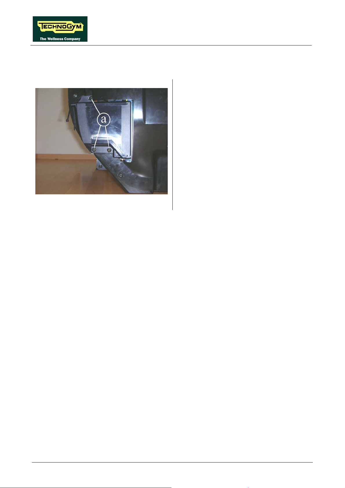
JOG EXCITE: Service & Maintenance Manual - rev. 1.1
7.14. DISASSEMBLING THE POWER SUPPLY BOX
Carry out the procedure described in paragraph
7.9. “Disassembling the motor guard”.
1. Unplug the power supply cable from the AT
driver box.
2. Unplug the ground cable from the frame.
3. Back off the 3 screws a using a 4-mm hex
wrench.
4. Remove the power supply box.
To reassemble the power supply box, carry out
the above steps in reverse order.
Figure 7.14-1
Page 7.16
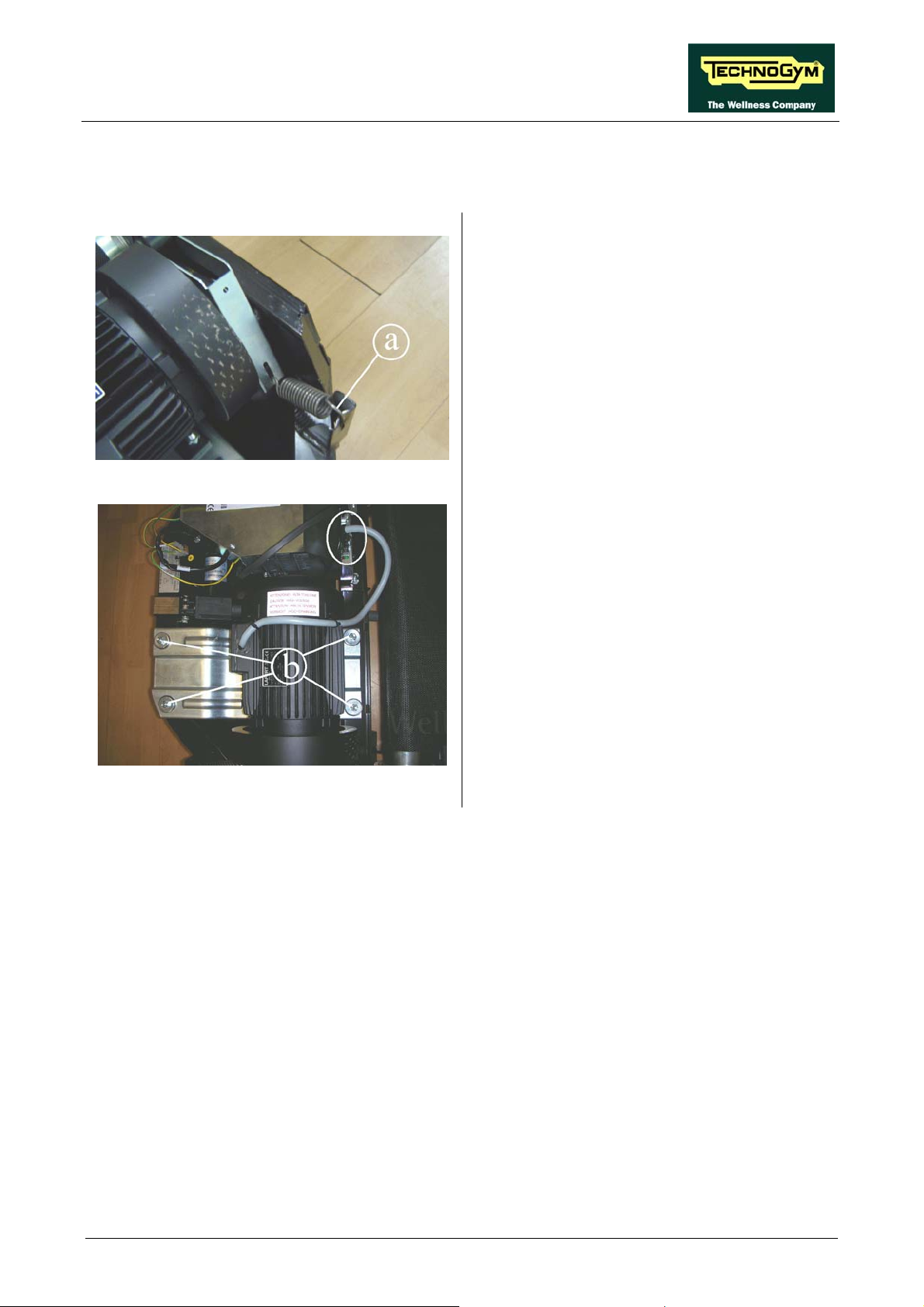
JOG EXCITE: Service & Maintenance Manual - rev. 1.1
7.15. DISASSEMBLING THE TREAD BELT MOTOR
Carry out the procedure described in paragraph
7.9. “Disassembling the motor guard”.
1. Release the spring a of the tensioning
mechanism between the drive-belt and the
front roller of the tread belt.
Figure 7.15-1
2. Unplug connector of the tread belt motor
cable on the AT driver.
3. Use a 13-mm wrench to back off the 4 nuts b
locking down the screws on the lower side
with a 6-mm hex wrench.
4. Remove from the machine the plate on which
is mounted the tread belt motor and
disassemble it.
To reassemble the tread belt motor, carry out the
above steps in reverse order.
Figure 7.15-2
Page 7.17

JOG EXCITE: Service & Maintenance Manual - rev. 1.1
7.16. DISASSEMBLING THE ELEVATION MOTOR
Carry out the procedure described in paragraph
7.12. “Disassembling the electrical box”.
1. Turn the machine over on one side.
2. Remove the split pin a and then the pin b
securing the elevation motor assembly to the
elevation frame.
Figure 7.16-1
3. Remove the split pin c and then the pin d.
4. Remove the elevation motor e.
To reassemble the elevation motor, carry out the
above steps in reverse order.
Figure 7.16-2
Page 7.18

JOG EXCITE: Service & Maintenance Manual - rev. 1.1
7.17. DISASSEMBLING THE TREAD BELT GROUP
With these operations it is possible to disassemble:
• footrest;
• driving roller;
• tread belt motor drive-belt;
• running deck;
• driven roller;
• tread belt;
• shock absorbers.
In order to carry out these operations, it is necessary to slacken the tread-belt tension. If
the belt is to be used again, follow the instructions given in paragraph 8.2. “Tensioning a
used tread belt” to correctly re-tension the belt.
Carry out the procedure described in paragraph
7.9. “Disassembling the motor guard”.
1. Back off the screw a using a 3-mm hex
wrench.
2. Back off the 2 screw b using a 3-mm hex
wrench.
3. Remove the rear cover by pulling it toward
the back.
Figure 7.17-1
Continued on following page →
Page 7.19

JOG EXCITE: Service & Maintenance Manual - rev. 1.1
4. Back off the screw c using a 5-mm hex
wrench.
5. Remove the footboard stop d.
6. Remove the footboard e by pulling it toward
the back.
Carry out the above steps on both the sides of the
machine.
7. Slacken the belt tension by backing off the
two screws f which act on the rear machine
roller, using an 8-mm hex wrench.
Figure 7.17-2
Slacken the screws acting by turns on
both the sides of the machine so that the
rear roller is always parallel to the front
one and to avoid to damage the roller
bearings.
8. Release the spring g of the tensioning
mechanism between the drive-belt and the
front roller of the tread belt.
Figure 7.17-3
Continued on following page →
Page 7.20

JOG EXCITE: Service & Maintenance Manual - rev. 1.1
Figure 7.17-4
9. Disengage the motor drive belt from the
pulley h on the front roller.
10. Remove the driving roller, extracting it from
the top on the right side and pulling it out
axially from the left.
11. Remove the motor drive belt from the motor
pulley.
Figure 7.17-5
12. Back off the 2 screws i which are fixing the
running deck to the frame of the machine,
using a 6-mm hex wrench.
13. Remove the running deck from the side.
14. Fully back off the screws which release the
tension of the rear roller.
15. Remove the rear roller.
16. Remove the tread belt.
When reassembling the running deck,
remember to insert the plastic bushing
“l” on the rear supports.
Figure 7.17-6
Continued on following page →
Page 7.21

JOG EXCITE: Service & Maintenance Manual - rev. 1.1
To disassemble the shock absorbers:
17. Lock down the nuts m using a 7-mm wrench
and back off the screws using a 3-mm hex
wrench, accessing it from below.
To reassemble the various components, carry out
the above steps in reverse order.
At the end of the procedure, check the
tension and alignment of the tread belt
as detailed at paragraph 8.1.
Figure 7.17-7
“Tensioning a new tread belt” or 8.2.
“Tensioning a used tread belt” and 8.3.
“Centering the tread belt”.
Page 7.22

JOG EXCITE: Service & Maintenance Manual - rev. 1.1
8. ADJUSTMENTS
8.1. TENSIONING A NEW TREAD BELT
1. After replacing the tread belt, place a tape
measure along the centre of the tread belt and
use a pen to make two reference marks
spaced exactly 1 meter apart.
Figure 8.1-1
2. Lock down by turns the screws a until the
distance between the reference marks
increases by 7 mm. Take care that the roller
is always approximately parallel with the one
on the front, to counteract the tension exerted
by the belt on the roller bearings.
After completing this procedure, any
further adjustments should be
performed using only the left-hand
alignment screw.
Figure 8.1-2
After completing this procedure, check
the centering of the tread belt as
instructed in paragraph 8.3. .
Page 8.1

JOG EXCITE: Service & Maintenance Manual - rev. 1.1
8.2. TENSIONING A USED TREAD BELT
1. Before slackening a used tread belt that
needs to be re-tensioned, place a tape
measure along the centre of the tread belt and
use a pen to make two reference marks
spaced exactly 1 meter apart.
Figure 8.2-1
2. After reassembling the used tread belt, lock
down by turns the screws a until the distance
between the two reference marks made
previously on the tread belt are once again
spaced 1 meter apart.
Figure 8.2-2
Take care that the roller is always
approximately parallel with the one on
the front, to counteract the tension
exerted by the belt on the roller
bearings.
This procedure is normally carried out
after replacing the rear or driving
roller, or in cases where a used tread
belt needs to be reassembled: it is not
possible to carry out the procedure
described in paragraph 8.1. because the
tread belt is not elastic.
After completing this procedure, check
the centering of the tread belt as
instructed in paragraph 8.3.
Page 8.2

JOG EXCITE: Service & Maintenance Manual - rev. 1.1
8.3. CENTERING THE TREAD BELT
1. Start the machine at a speed of 10 km/h.
2. Observe the movement of the tread belt,
correcting any tendency to shift to the right
or left exclusively by adjusting the left
tension screw a. Locking down this screw
favors shifting of the belt to the right and
vice versa.
3. Gradually increase the speed to 16 km/h,
Figure 8.3-1
making any small adjustments that are
necessary until the tread belt is perfectly
centered.
Page 8.3

JOG EXCITE: Service & Maintenance Manual - rev. 1.1
8.4. POSITION OF THE LIMIT SWITCH
1. Back off the 2 screws a fixing the limit
switch stop plate.
2. Adjust the position of the plate so that setting
0% of elevation, the distance x from the
microswitch and the plate is about 5 mm.
3. After making the adjustment, lock down the
screws a backed off previously.
Figure 8.4-1
Page 8.4

JOG EXCITE: Service & Maintenance Manual - rev. 1.1
9. MACHINE CONFIGURATION
9.1. USER MENU CONFIGURATION
The machine configuration procedure is invoked by simultaneously pressing the keys ENTER, ↑,
CLEAR when the machine is in standby mode. The following prompt appears on the LED display:
ENTER PASSWORD:
To access the procedure, insert the password 2406 and press ENTER to confirm. To enter the
password without the numeric keypad, enter one digit at a time using the ↑ and ↓ keys to change
the value and the +/- GOAL keys to scroll to the next character.
At this point the machine display begins showing the current configuration, structured as in the
diagram below:
USER MENU
Language
Distance
MAX ti m e
Paus e tim e
Default age
Default we ight
Default time
Default cal ories
Default di stance
TGS
Keys
HR
Cus to m mess.
Up/Down
Default co n fig.
Format P&P
User detect
SN
Ready2Run
9.1.1. LANGUAGE
After selecting a language from the list of those available, all messages subsequently displayed by
the machine will be in the chosen language. To change the selection, when the LED matrix shows
the current setting:
Page 9.1

JOG EXCITE: Service & Maintenance Manual - rev. 1.1
LANGUAGE : xxx
Press the +/- GOAL keys to select the desired language from the options available. Press ENTER
to confirm the choice, use the + or – speed keys to move to the next or previous parameter.
9.1.2. DISTANCE
It is possible to choose between EUROPEAN units (kg and km) or IMPERIAL units (pounds and
miles). To change the selection, when the LED matrix shows the current setting:
DISTANCE : xxx
Press the +/- GOAL keys to select the desired unit of measurement from the options listed in the
table below:
DISTANCE
KM <default>
MLS
Press ENTER to confirm the selection, use the + or – speed keys to move to the next or preceding
parameter.
9.1.3. MAXIMUM EXERCISE TIME
It is possible to set a maximum duration for the exercise in minutes, with values ranging from 1 to
9999. To change the setting, when the LED matrix shows the current maximum time limit:
MAX TIME: xxx
Press the ENTER key to modify the parameter: when the current value of the parameter starts to
blink, press the CLEAR key to erase the current value and then enter one digit at a time using the ↑
and ↓ keys to change the value and the +/- GOAL keys to scroll to the next character.
Press ENTER to confirm the selection, use the + or – speed keys to move to the next or preceding
parameter.
The default value of this parameter is 9999.
9.1.4. PAUSE TIME
It is possible to set a maximum duration of the pause for every exercise in seconds, with values
ranging from 10 to 999. To change the setting, when the LED matrix shows the current maximum
pause time:
PAUSE TIME : xxx
Press the ENTER key to change the parameter: the current value of the parameter will start to
blink, at this point press the CLEAR key to erase the current value and then enter one digit at a
time using the ↑ and ↓ keys to change the value and the +/- GOAL keys to scroll to the next
character.
Press ENTER to confirm the changes made, and use the + or – speed keys to move to the next or
preceding parameter.
The default value of this parameter is 60.
Page 9.2

JOG EXCITE: Service & Maintenance Manual - rev. 1.1
9.1.5. DEFAULT AGE
It is possible to set the default age for a generic user, with values ranging from 10 to 99. To change
the setting, when the LED matrix shows the current setting:
DEFAULT AGE : xx
Press the ENTER key to change the parameter: the current value of the parameter will start to
blink, at this point press the CLEAR key to erase the current value and then enter one digit at a
time using the ↑ and ↓ keys to change the value and the +/- GOAL keys to scroll to the next
character.
Press ENTER to confirm the changes made, and use the + or – speed keys to move to the next or
preceding parameter.
The default value of this parameter is 30.
9.1.6. DEFAULT WEIGHT
It is possible to set the default weight of a generic user in KG, with values ranging from 10 to 999.
To change the setting, when the LED matrix shows the current setting:
DEFAULT WEIGHT : KG xxx
Press the ENTER key to change the parameter: the current value of the parameter will start to
blink, at this point press the CLEAR key to erase the current value and then enter one digit at a
time using the ↑ and ↓ keys to change the value and the +/- GOAL keys to scroll to the next
character.
Press ENTER to confirm the changes made, and use the + or – speed keys to move to the next or
preceding parameter.
The default value of this parameter is 70.
9.1.7. DEFAULT TIME
It is possible to set the default duration of the exercise in minutes, with values ranging from 10 to
999. To change the setting, when the LED matrix shows the current time:
DEFAULT TIME : MIN. xxx
Press the ENTER key to change the parameter: the current value of the parameter will start to
blink, at this point press the CLEAR key to erase the current value and then enter one digit at a
time using the ↑ and ↓ keys to change the value and the +/- GOAL keys to scroll to the next
character.
Press ENTER to confirm the changes made, and use the + or – speed keys to move to the next or
preceding parameter.
The default value of this parameter is 15.
Page 9.3

JOG EXCITE: Service & Maintenance Manual - rev. 1.1
9.1.8. DEFAULT CALORIES
It is possible to set the calories for every exercise, with values ranging from 10 to 999. To change
the setting, when the LED matrix shows the current setting:
DEFAULT CALORIES : xxx
Press the ENTER key to change the parameter: the current value of the parameter will start to
blink, at this point press the CLEAR key to erase the current value and then enter one digit at a
time using the ↑ and ↓ keys to change the value and the +/- GOAL keys to scroll to the next
character.
Press ENTER to confirm the changes made, and use the + or – speed keys to move to the next or
preceding parameter.
The default value of this parameter is 300.
9.1.9. DEFAULT DISTANCE
It is possible to set the distance for every exercise in Km, with values ranging from 1 to 999. To
change the setting, when the LED matrix shows the current setting:
DEFAULT DISTANCE : KM xxx
Press the ENTER key to change the parameter: the current value of the parameter will start to
blink, at this point press the CLEAR key to erase the current value and then enter one digit at a
time using the ↑ and ↓ keys to change the value and the +/- GOAL keys to scroll to the next
character.
Press ENTER to confirm the changes made, and use the + or – speed keys to move to the next or
preceding parameter.
The default value of this parameter is 10.
9.1.10. ENABLE TGS
It is possible to enable or disable the use of the TGS reader. To change the selection, when the LED
matrix shows the current setting:
TGS: xxx
Press the +/- GOAL keys to select the desired option from those listed in the table below:
TGS
ENABLED <default>
DISABLED
Press ENTER to confirm the selection, use the + or – speed keys to move to the next or preceding
parameter.
Page 9.4
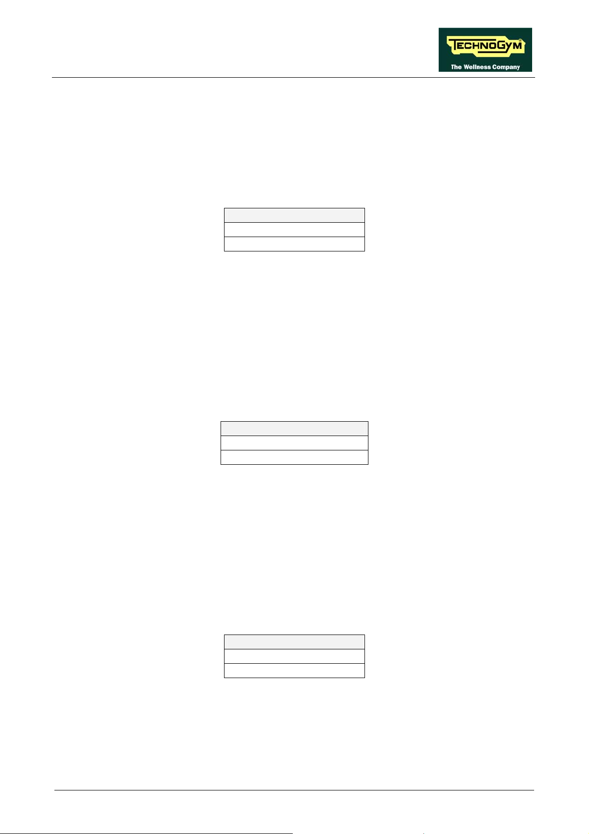
JOG EXCITE: Service & Maintenance Manual - rev. 1.1
9.1.11. ENABLE KEYBOARD
It is possible to disable the keyboard so that the machine can only be used with the TGS. To change
the setting, when the LED matrix shows the current one:
KEYS: xxx
Press the +/- GOAL keys to select the desired option out of those listed in the table below:
KEYS
ENABLED <default>
DISABLED
Press ENTER to confirm the selection, use the + or – speed keys to move to the next or preceding
parameter.
9.1.12. MODIFIABLE TARGET HEART RATE
It is possible to enable or disable modification of the target heart rate during a constant heart rate
exercise. To change the selection, when the LED matrix shows the current value:
HR: xxx
Press the +/- GOAL number keys to select the desired option out of those listed in the table below:
HR
MODIFIABLE <default>
NOT MODIFIABLE
Press ENTER to confirm the selection, use the + or – speed keys to move to the next or preceding
parameter.
9.1.13. ENABLE CUSTOM MESSAGES
It is possible to configure whether a custom message is displayed when the machine is in the
standby state. To change the selection, when the LED matrix shows the current setting:
CUSTOM MESS. : xxx
Press the +/- GOAL number keys to select the desired option out of those listed in the table below:
CUSTOM MESS.
YES <default>
NO
Press ENTER to confirm the selection, use the + or – speed keys to move to the next or preceding
parameter.
Page 9.5

JOG EXCITE: Service & Maintenance Manual - rev. 1.1
9.1.14. ENABLE UP/DOWN MOTOR
This parameter enables or disables use of the machine incline. To change the selection, when the
LED matrix shows the current setting:
UP-DOWN: xxx
Press the +/- GOAL keys to select the desired option out of those listed in the table below:
UP-DOWN
ENABLED <default>
DISABLED
Press ENTER to confirm the selection, use the + or – speed keys to move to the next or previous
parameter.
9.1.15. RESETTING PARAMETERS TO DEFAULT VALUES
It is possible to reset the user menu parameters to their default values. To select the function, when
the LED matrix shows:
DEFAULT CONFIG.
Press ENTER to confirm the operation, use the + or – speed keys to move to the next or preceding
parameter. If the ENTER key is pressed the LED matrix will show:
CONFIRM ?
press ENTER to confirm, or cancel by pressing the CLEAR key for a few seconds.
9.1.16. FORMAT P&P
This function formats a TGS key for Plug&Play mode operation. To select the function, when the
LED matrix shows:
FORMAT P&P
Press ENTER to confirm the operation, use the + or – speed keys to move to the next or preceding
parameter.
At the end of the format procedure, hold down the CLEAR key for a few seconds to exit. The
CLEAR key can be pressed at any time to interrupt the procedure and revert to standby mode.
9.1.17. USER DETECT
This function is able to detect the presence of a user running on the tread belt during an exercise
session. It is possible to configure a minimum speed at which the machine will determine that the
user has stopped running on the treadmill, and interrupt the exercise session if the condition persists
for one minute. To change the setting, when the LED matrix shows the current duration:
USER DETECT: xxx
Page 9.6
 Loading...