

Page 1

SERVICE & MAINTENANCE MANUAL
REV. 3.0
Page 2

Page 3

The information contained in this manual is intended for QUALIFIED TECHNICIANS who have
completed a specific TECHNOGYM training course and are authorized to perform machine start-up
and adjustment procedures as well as extraordinary maintenance or repairs which require a thorough
knowledge of the machine, its operation, its safety devices and working procedures.
CAREFULLY READ THE INFORMATION CONTAINED IN
THIS MANUAL BEFORE PERFORMING ANY MAINTENANCE
PROCEDURES ON THE MACHINE
DANGEROUS VOLTAGES
PRESENT EVEN WHEN THE
NOTE
The information contained in this document is subject to change without notice.
Technogym does not guarantee this documentation in any way. Technogym shall not be held
responsible for any errors contained in this manual and declines all liability for accidents or
damages resulting from the supply, characteristics or use of this manual.
This document contains proprietary information that is protected by copyright. All rights reserved.
No part of this document may be photocopied, reproduced or translated into another language
without the prior written consent of Technogym.
The Technogym® trademark is property of Technogym S.r.l.
The Forma™ trademark is property of Technogym S.r.l.
MACHINE IS TURNED OFF
Page 4

Page 5

FORMA: Service & Maintenance manual - rev. 3.0
Contents
1. GENERAL NOTICES........................................................................................................................................... 1.1
NTRODUCTION
1.1. I
ECOMMENDATIONS
1.2. R
ENERAL RULES FOR REPAIR PROCEDURES
1.3. G
2. TECHNICAL CHARACTERISTICS .................................................................................................................. 2.1
2.1. M
2.2. E
2.3. A
2.4. C
2.5. W
3. PRINCIPLES OF OPERATION.......................................................................................................................... 3.1
3.1. B
3.2. T
3.3. UP-
3.4. F
ECHANICAL CHARACTERISTICS
LECTRICAL CHARACTERISTICS
MBIENT SPECIFICATIONS
ONFORMITY TO REGULATIONS
IRING DIAGRAM
2.5.1. Version currently in production........................................................................................................ 2.2
2.5.2. Connectors ........................................................................................................................................ 2.3
2.5.3. Wiring ............................................................................................................................................... 2.4
2.5.4. Previous model................................................................................................................................ 2.10
LOCK DIAGRAM
3.1.1. Cardio transmitter............................................................................................................................. 3.1
3.1.2. Cardio receiver ................................................................................................................................. 3.1
3.1.3. Display .............................................................................................................................................. 3.2
3.1.4. Driver board .....................................................................................................................................3.2
3.1.5. Inverter.............................................................................................................................................. 3.3
3.1.6. Belt motor.......................................................................................................................................... 3.3
3.1.7. Up-down motor ................................................................................................................................. 3.3
3.1.8. Power supply..................................................................................................................................... 3.3
3.1.9. Voltage selector switch .....................................................................................................................3.4
3.1.10. Transformer....................................................................................................................................... 3.4
3.1.11. Safety switch ...................................................................................................................................... 3.4
3.1.12. Fan .................................................................................................................................................... 3.4
3.1.13. Fan interface board........................................................................................................................... 3.4
READ-BELT MOTOR DRIVE
3.2.1. Mechanics ......................................................................................................................................... 3.5
3.2.2. Controls............................................................................................................................................. 3.5
3.2.3. The signals involved.......................................................................................................................... 3.6
DOWN MOTOR DRIVE
3.3.1. Mechanics ......................................................................................................................................... 3.8
3.3.2. Controls............................................................................................................................................. 3.8
3.3.3. The signals involved.......................................................................................................................... 3.9
AN DRIVE
3.4.1. Mechanics ....................................................................................................................................... 3.11
3.4.2. Controls........................................................................................................................................... 3.11
3.4.3. The signal involved ......................................................................................................................... 3.12
................................................................................................................................................. 1.1
........................................................................................................................................ 1.1
...................................................................................................... 1.2
...................................................................................................................... 2.1
........................................................................................................................ 2.1
................................................................................................................................2.1
........................................................................................................................ 2.1
............................................................................................................................................. 2.2
.............................................................................................................................................. 3.1
.............................................................................................................................. 3.5
................................................................................................................................... 3.8
...................................................................................................................................................... 3.11
4. ACCESSORIES...................................................................................................................................................... 4.1
ONNECTING TO THE TGS
4.1. C
5. INSTALLATION INSTRUCTIONS .................................................................................................................... 5.1
PECIFICATIONS AND REQUIREMENTS
5.1. S
NSTALLATION
5.2. I
IRST POWER-ON
5.3. F
6. TROUBLESHOOTING.........................................................................................................................................6.1
.................................................................................................................................................. 5.1
.............................................................................................................................................. 5.1
................................................................................................................................. 4.1
............................................................................................................... 5.1
Page i
Page 6

FORMA: Service & Maintenance manual - rev. 3.0
HE DISPLAY DOES NOT ILLUMINATE
6.1. T
HE DISPLAY SHOWS
6.2. T
HE DISPLAY SHOWS
6.3. T
6.3.1. The inverter display shows E01, E02, E03, E04 or E05................................................................... 6.9
6.3.2. The inverter display shows E06 or E07 ..........................................................................................6.11
6.3.3. The inverter display shows E08, E10, E11 or E22.......................................................................... 6.12
6.3.4. The inverter display shows E09 ...................................................................................................... 6.13
6.3.5. The inverter display shows E12 ...................................................................................................... 6.15
6.3.6. The inverter display shows E14 ...................................................................................................... 6.17
6.3.7. The inverter display shows E15 ...................................................................................................... 6.18
6.3.8. The inverter display shows E21 ...................................................................................................... 6.20
6.3.9. The inverter display does not show any error................................................................................. 6.21
HE BELT MOTOR IS JERKING
6.4. T
HE BELT MOTOR STARTS WITH DELAY
6.5. T
HE DISPLAYED SPEED IS INCORRECT
6.6. T
HE DISPLAY SHOWS
6.7. T
HE UP-DOWN MOVES IN ONLY ONE DIRECTION
6.8. T
HE DISPLAYED ELEVATION IS INCORRECT
6.9. T
HE FAN IS NOT WORKING
6.10. T
HERE IS NO HEART RATE SIGNAL
6.11. T
HE HEART RATE SIGNAL IS INCORRECT
6.12. T
“SAFETY SWITCH”..................................................................................................... 6.6
“E 3”............................................................................................................................... 6.7
.......................................................................................................................... 6.23
“E 5”............................................................................................................................. 6.28
.............................................................................................................................. 6.36
................................................................................................................ 6.2
.......................................................................................................... 6.24
............................................................................................................. 6.25
.............................................................................................. 6.32
..................................................................................................... 6.34
................................................................................................................... 6.39
......................................................................................................... 6.40
7. DISASSEMBLY OF COMPONENTS ................................................................................................................. 7.1
ISASSEMBLING THE DISPLAY
7.1. D
ISASSEMBLING THE
7.2. D
ISASSEMBLING THE DISPLAY BOARDS
7.3. D
ISASSEMBLING THE KEYBOARD
7.4. D
ISASSEMBLING THE CARDIO RECEIVER
7.5. D
ISASSEMBLING THE SAFETY SWITCH
7.6. D
ISASSEMBLING THE MOTOR GUARD
7.7. D
ISASSEMBLING THE REAR ROLLER
7.8. D
ISASSEMBLING THE MOTOR ROLLER AND DRIVE-BELT
7.9. D
ISASSEMBLING THE TREAD-BELT AND RUNNING TRACK
7.10. D
ISASSEMBLING THE SHOCK ABSORBERS
7.11. D
ISASSEMBLING THE FOOTREST GUIDE
7.12. D
ISASSEMBLING THE SIDE GUARDS
7.13. D
ISASSEMBLING THE MOTOR GUARD GRILLE
7.14. D
ISASSEMBLING THE TREAD-BELT MOTOR
7.15. D
ISASSEMBLING THE ELECTRONIC CIRCUIT BOARDS
7.16. D
MONTAGGIO SCHEDA INTERFACCIA VENTOLA
7.17. S
ISASSEMBLING THE INVER TER
7.18. D
ISASSEMBLING THE COLUMN AND RUBBER GUARD
7.19. D
ISASSEMBLING THE UP-DOWN MOTOR
7.20. D
ISASSEMBLING THE UP-DOWN FRAME
7.21. D
ISASSEMBLING THE HANDLEBARS
7.22. D
8. ADJUSTMENTS.................................................................................................................................................... 8.1
EPROM.......................................................................................................................... 7.2
.......................................................................................................................... 7.1
............................................................................................................. 7.3
...................................................................................................................... 7.4
........................................................................................................... 7.5
............................................................................................................... 7.6
................................................................................................................ 7.7
.................................................................................................................. 7.8
.................................................................................. 7.10
................................................................................ 7.12
....................................................................................................... 7.14
........................................................................................................... 7.15
................................................................................................................. 7.16
.................................................................................................. 7.17
...................................................................................................... 7.18
....................................................................................... 7.19
............................................................................................... 7.21
...................................................................................................................... 7.22
....................................................................................... 7.23
.......................................................................................................... 7.24
........................................................................................................... 7.25
................................................................................................................ 7.26
ENSIONING A NEW TREAD-BELT
8.1. T
ENSIONING A USED TREAD-BELT
8.2. T
ENTERING THE TREAD-BELT
8.3. C
LIGNING THE TREAD-BELT MOTOR DRIVE-BELT
8.4. A
ENSIONING THE TREAD-BELT MOTOR DRIVE BELT
8.5. T
ALIBRATING THE TREAD-BELT SPEED
8.6. C
DJUSTING THE UP-DOWN MOTOR CURRENT LIMITER
8.7. A
9. MACHINE CONFIGURATION .......................................................................................................................... 9.1
LANGUAGE CONFIGURATION
9.1.
IEWING THE WORKING PARAMETERS
9.2. V
...................................................................................................................... 8.1
..................................................................................................................... 8.2
........................................................................................................................... 8.3
.............................................................................................. 8.4
........................................................................................... 8.5
............................................................................................................. 8.6
....................................................................................... 8.7
............................................................................................................................. 9.1
.............................................................................................................. 9.2
Page ii
Page 7

FORMA: Service & Maintenance manual - rev. 3.0
9.2.1. Hours of machine operation ............................................................................................................. 9.2
9.2.2. Hours of tread-belt motor operation................................................................................................. 9.2
9.2.3. Minutes of up-down motor operation................................................................................................ 9.2
9.2.4. Distance Covered.............................................................................................................................. 9.2
9.3. M
9.4.
9.5. P
ODIFYING THE WORKING PARAMETERS
9.3.1. Hours of machine operation ............................................................................................................. 9.3
9.3.2. Hours of tread-belt motor operation................................................................................................. 9.3
9.3.3. Minutes of up-down motor operation................................................................................................ 9.3
9.3.4. Distance covered............................................................................................................................... 9.3
UP-DOWN TEST
ROGRAMMING THE
9.5.1. Monitor function parameters ............................................................................................................ 9.6
9.5.2. Modified parameter settings ............................................................................................................. 9.6
................................................................................................................................................. 9.4
HITACHI SJ100
.......................................................................................................... 9.3
INVERTER
............................................................................................. 9.5
10. SCHEDULED MAINTENANCE ....................................................................................................................... 10.1
XTERNAL CLEANING OPERATIONS
10.1. E
10.1.1. Setting up the operation .................................................................................................................. 10.1
10.1.2. Cleaning operations ........................................................................................................................ 10.1
10.1.3. Operazione di lubrificazione del nastro e pianale di corsa per Forma 3 ....................................... 10.1
OUTINE MAINTENANCE OPERATIONS
10.2. R
10.2.1. Internal cleaning operations ........................................................................................................... 10.3
10.2.2. Checking the state of wear............................................................................................................... 10.3
10.2.3. Checking the tension and centering of the tread-belt...................................................................... 10.3
10.2.4. Checking the “Safety switch”.......................................................................................................... 10.3
PECIAL MAINTENANCE OPERATIONS
10.3. S
10.3.1. Carrying out the routine maintenance procedure ........................................................................... 10.4
10.3.2. Checking the working conditions ....................................................................................................10.4
10.3.3. Checking the wiring and connections.............................................................................................. 10.4
10.3.4. Checking the display........................................................................................................................ 10.4
10.3.5. Checking the wear and lubrication of the tread-belt and running track......................................... 10.4
10.3.6. Checking the wear of the motor roller............................................................................................. 10.5
10.3.7. Checking the wear of the rear roller ............................................................................................... 10.5
10.3.8. Checking the shock absorbers......................................................................................................... 10.5
10.3.9. Checking the wear of the rubber handlebar cover.......................................................................... 10.5
10.3.10. Checking the tread-belt motor drive-belt ........................................................................................10.5
10.3.11. Checking the speed calibration ....................................................................................................... 10.5
10.3.12. Checking the operation of the cardio receiver ................................................................................ 10.5
11. APPENDIX........................................................................................................................................................... 11.1
................................................................................................................. 10.1
............................................................................................................ 10.3
.............................................................................................................. 10.4
ECHNICAL NOTES ON CARDIO RECEIVERS
11.1. T
11.1.1. Type of ASIC.................................................................................................................................... 11.2
11.1.2. Presence of electromagnetic fields.................................................................................................. 11.2
11.1.3. Reducing receiver sensitivity ........................................................................................................... 11.3
11.1.4. Mechanical vibrations..................................................................................................................... 11.4
11.1.5. Position of the receiver.................................................................................................................... 11.4
11.1.6. Routing of cables ............................................................................................................................. 11.5
11.2. HITACHI SJ100
ROCEDURE FOR CLEARING THE ERROR MEMORY ON HITACHI
11.3. P
INVERTER ERROR CODES
..................................................................................................... 11.1
..................................................................................................... 11.6
INVERTER
SJ100
............................................ 11.8
Page iii
Page 8

FORMA: Service & Maintenance manual - rev. 3.0
Page intentionally left blank
Page iv
Page 9

FORMA: Service & Maintenance manual - rev. 3.0
1. GENERAL NOTICES
1.1. INTRODUCTION
This document is reserved for Technogym Service technicians, and is intended to provide
authorized personnel with the necessary information to correctly carry out repairs and maintenance.
A thorough knowledge of the technical information contained in this manual is essential for
completing the professional training of the operator.
In order to facilitate consultation, the paragraphs are accompanied by schematic drawings which
illustrate the procedure being described.
This manual contains notices and symbols which have a specific meanings:
WARNING: non observance may result in accident or injury.
ATTENTION: non observance may cause damage to the machine.
Information about the operation in progress.
OBSERVE: observation about the operation in progress.
1.2. RECOMMENDATIONS
Technogym recommends the following steps for planning repair procedures:
• Carefully evaluate the customer’s description of the machine malfunction and ask all the
necessary questions to clarify the symptoms of the problem.
• Clearly diagnose the causes of the problem. This manual provides the fundamental theoretical
basis, which must then be integrated by personal experience and attendance at the training
courses periodically offered by Technogym.
• Rationally plan the repair procedure so as to minimize the downtime necessary for procuring
spare parts, preparing tools, etc.
• Access the component to be repaired, avoiding any unnecessary operations. In this regard it will
be useful to refer to the disassembly sequence described in this manual.
Page 1.1
Page 10

FORMA: Service & Maintenance manual - rev. 3.0
1.3. GENERAL RULES FOR REPAIR PROCEDURES
1. Always mark any parts or positions which may be confused with each other at the time of
reassembly.
2. Use original Technogym spare parts and lubricants of the recommended brands.
3. Use special tools where specified.
4. Consult the technical circulars, which may contain more up-to-date information on adjustments
and maintenance than those contained in this manual.
5. Before starting the repair procedure, make sure that the recommended tools are available and in
good condition.
6. For the procedures described in this manual, use only the specified tools.
OBSERVE: The tool sizes quoted in this manual are expressed in mm.
Page 1.2
Page 11

FORMA: Service & Maintenance manual - rev. 3.0
2. TECHNICAL CHARACTERISTICS
2.1. MECHANICAL CHARACTERISTICS
Width 73 cm
Length 180 cm
Height 132 cm
Weight 130 Kg
2.2. ELECTRICAL CHARACTERISTICS
Mains voltage 220 V
Frequency 50 Hz
Consumption 1500 VA
Fuses 5x20 2xT8AH
2.3. AMBIENT SPECIFICATIONS
Temperature
Humidity
Operating from 5° to 35° C
Storage from -20 to 55° C
Operating from 30% to 80% non-condensing
Storage from 5% to 85% non-condensing
2.4. CONFORMITY TO REGULATIONS
The machine conforms to the following directives:
EMI
Safety
Exercise equipment
Directive
Europe USA
EN 60601-1-2
EN 60601-1:90
+A1:93
+A12:93
+A2:95
+A13:96
EN 957-1
73/23/EEC
93/68/EEC
89/336/EEC
N.A.
Page 2.1
Page 12

FORMA: Service & Maintenance manual - rev. 3.0
2.5. WIRING DIAGRAM
2.5.1. VERSION CURRENTLY IN PRODUCTION
This machine version, subsequently identified with the name Forma 3, has been in production
starting from SN 01000881. It differs from the preceding version as follows:
• Fan for improved cooling of the motor group;
• Electronic circuit board for starting the fan when the motor is running;
• New motor group equipped with scaled-up flywheel;
• New driving roller with larger diameter pulley;
• Hole in the guard for lubrication of the table;
• New inverter configuration parameters;
• New operating SW.
The wiring diagram is given below:
Page 2.2
Page 13

FORMA: Service & Maintenance manual - rev. 3.0
2.5.2. C
• CPU board
name type of connector connection
K1 AMP MODU I 4x1 pin f. to driver board (low voltage input)
K2 AMP MODU I 2x1 pin f. to LED board (low voltage output)
K4 AMP MODU II 9x2 pin f. to driver board (actuator drives)
K6 AMP MODU II 4x1 pin f. to serial connector for TGS
K12 Flat 5x2 pin f. to LED board (LED driver output)
K14 AMP MODU II 4x1 pin f. to cardio receiver
EM AMP MODU II 2x1 pin f. to emergency button
• LED board
name type of connector connection
K2 AMP MODU I 2x1 pin f. to CPU board (low voltage input)
K12 Flat 5x2 pin f. to CPU board (LED driver input)
• Driver board
name type of connector connection
J1 AMP MATE-N-LOCK 3x2 pin f. to up-down motor
J2 2 pin terminal block to transformer (low voltage ac input)
J3 AMP MODU I 4x1 pin f. to power supply (low voltage input)
J4 AMP MODU I 4x1 pin f. to CPU (low voltage output)
J5 AMP MODU II 6x1 pin f. to inverter (inverter drive)
J6 AMP MODU II 9x2 pin f. to CPU board (actuator drive)
• Power supply
name type of connector connection
CN1 PANDUIT 6 pin m. to filter (mains voltage input)
CN2 PANDUIT 6 pin m. to driver board (low voltage output)
• Fan interface board
name type of connector connection
CN1 AMP MODU I 2x1 pin f. to inverter
CN2 4-pin terminal block IN: from power inlet block (mains voltage
ONNECTORS
input)
OUT: to fan (mains voltage output with
isolating relay on the circuit board)
Page 2.3
Page 14

FORMA: Service & Maintenance manual - rev. 3.0
• Portable connectors
name type of connector connection
CN28 MOLEX mini-fit 7x2 m. portable to CPU board (actuator drive)
CN29 MOLEX mini-fit 7x2 f. portable to driver board (actuator drive)
CN39 Terminal block to filter, power supply, inverter and selector
CN46 MOLEX mini-fit 3x2 f. portable to up-down motor
2.5.3. W
IRING
FR-1/A: Power supply cable
Power inlet socket – Filter - Fan interface board
Power inlet
socket
Fast on Live
Fast on Neutral
Fast on - -
-
This cable incorporates a 348 Ohm, 100 Mhz ferrite with coil on the live and neutral conductors.
Signal Color Filter Fan
Black Fast on - Black - Fast on -
Blue Fast on - Blue - Fast on -
Earth
Yellow-green
Yellow-green
Fast on -
PE
interface
board
Eyelet
FR-2: High voltage power supply cable
Filter – High voltage distribution terminal block
Filter Signal Color Terminal block
Fast on Live Black L
Fast on Neutral Blue N
Fast on Earth Yellow PE
CN39
FR-3/L: Power supply high voltage input cable
High voltage distribution terminal block – Power supply
Terminal block
CN39
N Neutral Blue 4
L Live Black 6
Signal Color Power supply
CN1
FR-4: Inverter high voltage input cable
High voltage distribution terminal block – Inverter
Terminal block
CN39
N Neutral Blue N
L Live Black L1
Signal Color Inverter
Page 2.4
Page 15

FORMA: Service & Maintenance manual - rev. 3.0
FR-5: Transformer high voltage input cable
High voltage distribution terminal block – Selector
Terminal block
CN39
N Neutral Blue 4
L Live Black 1
Signal Color Selector
FR-6: Low voltage power supply cable
Power supply – Driver board
Power supply
CN2
1 + 12 Vdc Red 1 3 + 5 Vdc Orange 4 4 ground Grey 3 -
5 ground
Signal Color Driver
FR-7: Inverter cable
Driver board – Inverter
Driver board
J5
- Thermal cutout Green 3 2
1 White -
- White P24
2 Start Grey 1 3 Alarm Red AL0 4 Alarm Gnd Purple AL1 5 Speed Brown O 6 Speed Gnd Black L -
Signal Color Inverter CN43
Thermal cutout Gnd
FR-8: Tread-belt motor cable
Inverter – Tread-belt motor
Inverter Signal Color Motor CN43
U Phase U Black 1 already connected V Phase V Black 2 already connected -
W Phase W Black 3 already connected -
- Thermal cutout Black 4 already connected 1
- Thermal cutout Gnd Black 5 already connected 2
PE Earth Black 6 already connected -
Terminal
board
J3
Black 2 -
Yellow-
green
Orange 11
- PE
block
CN39
1
Page 2.5
Page 16

FORMA: Service & Maintenance manual - rev. 3.0
FR-9: Up-down motor cable
Portable connector – Up-down motor cable
Portable
CN46
1 Motor + White already connected
2 Motor - Blue already connected
5 Up-down motor pulses Red already connected
6 Pulse Gnd Black already connected
Signal Color Up-down motor
FR-10: Braking resistor cable
Inverter – Braking resistor
Inverter Signal Color Resistor
1 Positive White already connected
RB Negative White already connected
FR-11: CPU cable – upper section
CPU board – Portable connector
CPU board
K1 K4
1 - +12 Vdc Red 6
2 - Gnd Black 7
3 - Gnd Grey 13
4 - +5 Vdc Orange 14
- 2 +5 Vdc Red 8
- 3 Up-down motor “down” Green 1
- 4 tread-belt motor speed PWM Grey 9
- 5 Up-down motor “up” Yellow 2
- 6 Start tread-belt motor Brown 10
- 7 Up-down motor alarm Blue 3
- 8 Tread-belt motor alarm Orange-
- 9 Up-down motor pulses Purple 4
- 11 Pulse Gnd Black-green 5
- 12 Gnd Black 12
This cable incorporates a 348 Ohm, 100 Mhz coil-less ferrite.
Signal Color Portable
CN28
11
yellow
Page 2.6
Page 17

FORMA: Service & Maintenance manual - rev. 3.0
FR-12: CPU cable – lower section
Portable connector – Driver board
Signal
CN29
1 Up-down motor “down” Green - 3
2 Up-down motor “up” Yellow - 5
3 Up-down motor alarm Blue - 7
4 Up-down motor pulses Purple - 9
5 Pulse Gnd Black-green - 11
6 +12 Vdc Red 1 7 Gnd Black 2 8 +5 Vdc Red - 2
9 Tread-belt motor speed PWM Grey - 4
10 Start tread-belt motor Brown - 6
11 Tread-belt motor alarm Orange-
12 Gnd Black - 12
13 Gnd Grey 3 14 +5 Vdc Orange 4 -
FR-13: LED board supply cable
CPU board – LED board
CPU board
K2
1 +5 Vdc Red 1
2 Gnd Black 2
Signal Color LED board
FR-14: LED board signal cable
CPU board – LED board
CPU board
K12
1 - 1
2 STROLED 2
3 MUX2 3
4 MUX1 4
5 MUX0 5
6 OELED 6
7 SCK 7
8 MOSI 8
9 DOE 9
10 - 10
This cable incorporates a 65 Ohm, 100 MHz coil-less ferrite.
Signal Color LED board
Color Driver board Portable
J4 J6
- 8
yellow
K2
K12
Page 2.7
Page 18

FORMA: Service & Maintenance manual - rev. 3.0
FR-15: Up-down motor cable extension
Portable connector – Driver board
Portable
CN46
1 Motor + White 1
2 Motor - Blue 2
5 Up-down motor pulses Red 5
6 Pulse Gnd Black 6
Signal Color Driver board
J1
FR-16: Fan power supply cable
Fan interface board – Fan
Fan interface
board
OUT Live Black Fast on
OUT Neutral Blue Fast on
Signal Color Fan
FR-17: Fan driving cable
Fan interface board – Inverter
Fan interface
board
1 Fan enable Black L
2 Gnd Red CM2
Signal Color Inverter
RL-14: Heart rate meter cable
CPU board – Heart rate receiver
CPU board
K14
1 +5 Vdc Red 1
2 Pulse per beat Blue 2
3 Gnd Black 3
Signal Color Receiver
RL-17: Emergency cable
CPU board – Emergency button
CPU board
EM
1 Gnd White Already connected
2 Signal Black Already connected
Signal Color Emergency
button
Page 2.8
Page 19

FORMA: Service & Maintenance manual - rev. 3.0
RL-20: TGS cable
CPU board – Serial connector
CPU board
K6
1 +12 Vdc Yellow 1
2 Gnd Green 5
3 Tx White 3
4 Rx Brown 2
Note that this is a simplified description of the cables, which does not include the ground node
connections of the electronics box, the rear roller and the front roller.
Signal Color Serial connector
Page 2.9
Page 20

FORMA: Service & Maintenance manual - rev. 3.0
2.5.4. P
This machine version, subsequently identified with the name Forma 2:
REVIOUS MODEL
For the cables, refer to the description in the preceding paragraph with the exception of cables FR1/A and FR-7 which are described below:
FR-1/A: Filter cable
Power inlet
Page 2.10
Power inlet socket – Filter
Signal Color Filter PE
socket
Fast on Live Black Fast on Fast on Neutral Blue Fast on Fast on Yellow-green -
-
Earth
Yellow-green Fast on
Eyelet
Page 21

FORMA: Service & Maintenance manual - rev. 3.0
FR-7: Inverter cable
Driver board – Inverter
Driver board
J5
- Thermal cutout Green 3 2
1 White -
2 Start Grey 1 3 Alarm Red AL0 4 Alarm Gnd Purple AL1 5 Speed Brown O 6 Speed Gnd Black L -
Signal Color Inverter CN43
Thermal cutout Gnd
White P24
1
Page 2.11
Page 22

FORMA: Service & Maintenance manual - rev. 3.0
Page intentionally left blank
Page 2.12
Page 23

FORMA: Service & Maintenance manual - rev. 3.0
3. PRINCIPLES OF OPERATION
3.1. BLOCK DIAGRAM
The block diagram of the machine is shown in the figure below:
3.1.1. C
It is worn by the person using the machine, and transmits to the cardio receiver one pulse for every
heart beat that is detected.
Only the traditional version of the component (non coded) is used.
ARDIO TRANSMITTER
3.1.2. CARDIO RECEIVER
It is connected to the machine’s CPU board and receives the pulses sent by the transmitter. Its
reception area is approximately a circle of 1 meter of radius. If there is electromagnetic noise
(produced by high voltage lines, radio transmitters, monitors, motors, etc.) within its reception area,
Page 3.1
Page 24

FORMA: Service & Maintenance manual - rev. 3.0
the receiver becomes saturated and stops receiving any signal. If there are 2 transmitters within its
area of reception, it will receive signals from both, and may produce an error or irregular reading.
Only the traditional version of the component (non coded) is used.
3.1.3. D
This is the heart of the machine, which controls all the machine functions by executing the program
stored in EPROM. It receives information from the user (age, weight, etc.) during set-up of the
training session, from the cardio receiver (user’s heart rate), and from the driver board. It controls
the speed selected with the “+” “−” keys and the elevation selected with the “↑” “↓” keys or
according to the chosen training program. It receives the error signals for the tread-belt motor and
the up-down motor from the driver board, as well as the up-down motor pulses.
It consists of 2 circuit boards:
CPU board: contains the microprocessor and all the control logic of the machine. This circuit board
incorporates a set of 4 dip-switches which is not currently used.
LED board: contains the circuits for the LED indicators and the 7 segment display.
ATTENTION: The EPROM SW versions used on Forma 2 and Forma 3 are different,
due to differences in certain mechanical characteristics between the two machines. In
consequence:
• Forma 2: SW usable up to version 2.1.10;
• Forma 3: SW usable as of version 3.1.02.
ISPLAY
3.1.4. D
Consists of 3 distinct sections integrated into a single circuit board:
• Driver: receives from the display a digital inverter-enable signal and a PWM signal proportional
to the programmed speed, which it converts into a dc voltage for driving the inverter. In the
event of an anomaly, receives the error signal from the inverter and transmits it to the CPU
board.
The circuit board includes a trimmer, component R36, labeled “Reg. velocità” on the printed
circuit board, which regulates the conversion of the PWM into an analog signal in order to
adjust the motor speed.
• Up-down motor control: receives the incline “up” or “down” signals from the display, and
converts them into a voltage for driving the up-down motor. Generates its own supply voltage
and the dc supply voltage for the motor by means of the transformer and rectifier bridge.
Receives the pulses output by the sensor incorporated into the motor, filters them and sends
them to the CPU board. In the event of a motor overcurrent condition, shuts down the motor
drive and sends an alarm signal to the display.
The circuit board includes a trimmer, component R68, labeled “Reg. I Max” on the printed
circuit board, which adjusts the motor current limit.
RIVER BOARD
Page 3.2
Page 25

FORMA: Service & Maintenance manual - rev. 3.0
• DC voltages by-pass: receives the low voltages generated by the power supply and sends them
to the CPU board.
3.1.5. I
This is the device which supplies the three-phase belt motor. It receives a DC reference voltage
from the driver board. Variations in this voltage cause corresponding variations in the operating
frequency of the sinusoidal wave provided by the inverter to the motor phases, and hence change the
speed of the tread-belt. It handles motor drive errors and, in the event of an error, shuts down the
power supply to the motor and sends an alarm signal through the driver board to the display. The
event which caused the error is memorized as an error code.
The model used is Hitachi SJ100 version SJ100-011NFE with a power rating of 1.1 KW (1.5 Hp).
WARNING: The inverter is isolated from earth. It is fixed using plastic screws and
3.1.6. B
An asynchronous three-phase motor which, by means of a pulley and a poly-v belt, turns the driving
roller of the tread-belt. Each motor phase is equipped with a normally-closed bimetallic safety
which opens when the temperature exceeds a preset threshold, in order to safeguard the integrity of
the motor. The 3 bimetallic safeties are connected in series and reach the inverter as a NC external
input signal. When this contact opens, the inverter generates an alarm.
The tread-belt motor has a power of 1.1 KW (1.5 Hp).
NVERTER
washers to ensure its isolation from the machine frame.
ELT MOTOR
The motor used on Forma 3 is different from the one used on Forma 2.
WARNING: The tread-belt motor is isolated from earth. It is fixed using plastic
bushings and dowels to ensure its isolation from the machine frame.
3.1.7. UP-
This is a linear actuator equipped with a 24 V DC motor, incorporating a reduction unit and a rod
that is moved backward and forward by the motor. The rod actuates a frame connected to the front
wheels of the machine: when the rod moves it causes the frame to move, thereby raising or lowering
the machine.
The actuator has a built-in reed sensor which functions as an encoder, outputting pulses as the motor
turns. This provides the necessary feedback signal for determining the position of the rod and hence
the machine incline.
DOWN MOTOR
3.1.8. POWER SUPPLY
Receives the mains voltage at its input and outputs the DC voltages (+5 V and +12 V) which supply
the display and the inverter interface board. This power supply is equipped with mains voltage
autosensing.
Page 3.3
Page 26

FORMA: Service & Maintenance manual - rev. 3.0
3.1.9. V
This is a selector which, when used together with a transformer having 2 primary 110 VAC circuits,
ensures the correct power supply to the transformer when powered at either 110 VAC or 230 VAC.
Switching positions changes the connection of the 2 primary circuits on the standard transformer
from serial (for 230 VAC power supply) to parallel (for 110 VAC power supply). It is located on the
low kit electrical box to prevent accidental selections by clients that could interfere with machine
operation.
OLTAGE SELECTOR SWITCH
3.1.10. T
Is equipped with two 110 VAC primaries and one 18VAC/5A secondary. This transformer powers
the driver boards for the up-down section.
3.1.11. S
This is the user safety device. It is implemented by a reed relay which is NC when the “Safety
switch”, a plastic button containing a magnet, is correctly positioned on the display panel. Its signal
is input to the CPU board. If the user is in difficulty and detaches the “Safety switch” from the
display by pulling the attached cord, the contact opens and the CPU board detects the transition,
braking the motor to prevent the user from falling.
RANSFORMER
AFETY SWITCH
3.1.12. FAN
It is a supplementary fan which provides improved cooling of the motor, especially during low
speed operation. The fan receives a supply voltage from the fan interface board when the motor is
running.
3.1.13. F
The circuit board takes care of enabling the fan when the motor is running. In fact, it receives a
signal from the inverter which closes a relay contact on the circuit board, causing the supply voltage
to be sent to the fan input.
AN INTERFACE BOARD
Page 3.4
Page 27

FORMA: Service & Maintenance manual - rev. 3.0
3.2. TREAD-BELT MOTOR DRIVE
3.2.1. MECHANICS
The tread-belt is actuated by the motor through a linkage consisting of the motor pulley, the driving
roller and the belt which connects them. In this way, a given belt motor speed corresponds to a
predetermined linear tread-belt speed. The belt motor is controlled by the inverter which generates a
variable-frequency sine wave signal: variations in frequency cause the motor speed and hence the
tread-belt speed to vary.
3.2.2. C
To start the motor, the CPU board sends a Start signal to the inverter through the driver board,
enabling the inverter to drive the motor. After outputting this enable signal, the CPU board sets the
motor speed by sending a PWM signal to the driver board, which the driver board converts into an
analog input voltage to the inverter. The relationship between the analog input voltage and the
inverter output frequency is determined by the values of the configuration parameters in the inverter
program.
During its movement, the inverter checks the motor and, if any problems are detected (overvoltage,
overcurrent, SW and HW problems to the inverter, etc.) it halts the motor and sends an alarm signal
to the CPU board, which displays the error message “E3”.
To protect the motor from overheating, each motor phase has a thermal cutout connected in series. If
the temperature exceeds the threshold value, the thermal cutout opens and interrupts the circuit. The
inverter detects this condition as the opening of a NC external contact. In such a case the inverter
halts the motor and outputs an alarm signal to the CPU board, which displays the error message
cited above.
ONTROLS
Page 3.5
Page 28

FORMA: Service & Maintenance manual - rev. 3.0
3.2.3. T
HE SIGNALS INVOLVED
The machine controls the speed of the belt motor by means of the CPU board and the inverter
interface board, as shown in the following figure:
CPU board
4-12 6-12 8-12 K4
Start PWM
9-12 10-12 11-12 CN28
Start PWM
4-12 6-12 8-12 J6
Driver board
Alarm
Alarm
5-6 2-1 3-4 J5
Start Vref
Alarm
O-L 1-P24 AL1-AL0
Inverter
3-P24
with variable frequency
VAC
U-V-W
Thermal
protection
M
The speed control utilizes the following signals:
• Start signal
This is the signal generated by the CPU board to enable starting of the motor (pin 6-12 on
connector K4). When the tread-belt is stopped this signal is at logic level low (0.2 Vdc), whereas
immediately after the “Start” key on the display is pressed it goes high (4.8 Vdc).
This signal enters the driver board (pin 6-12 on connector J6), is processed and sent out (pin 2-1
on connector J5 of the driver board) to the inverter (pin 1-P24). In the belt-stopped conditions it
is -23.8 Vdc, while immediately after pressing the “Start” key on the display it is 0 Vdc.
Page 3.6
Page 29

FORMA: Service & Maintenance manual - rev. 3.0
• Speed reference signal
This is the signal generated by the CPU board (pin 4-12 on connector K4) to control the motor
speed. It is a PWM signal, i.e. a fixed-frequency square wave signal with variable duty cycle.
The logic of this control has the duty cycle decreasing with increasing speed, from a maximum
of approximately 5 Vdc down to a few hundred mVdc.
The signal enters the driver board (pin 4-12 on connector J5), is converted into a variable analog
signal between 0 and 10 Vdc, and sent out (pin 5-6 on connector J5 of the driver board) to the
inverter (pin O-L). The signal input to the inverter increases with increasing speed.
The relationship between the speed reference voltage and the inverter output frequency is
determined by the values of the configuration parameters in the inverter program.
• Variable frequency VAC signal
This is the variable frequency alternating voltage generated by the inverter (pin U-V-W) for
supplying the motor. The motor speed increases with increasing frequency.
• Thermal cutout signal
Each motor phase is equipped with a normally-closed thermal cutout which opens when the
temperature exceeds a preset threshold. The 3 thermal cutouts are connected in series and exit
the motor via a 2-wire cable connected to the inverter (3-P24). The inverter is programmed to
expect a NC signal on these pins. When at least one thermal cutout is tripped, the contact opens
and the inverter, detecting the open-circuit condition, generates an alarm signal.
• Alarm signal
This is the signal generated by the inverter (AL1-AL0) if a problem is detected in the motor
drive, or if the motor thermal cutouts open. It enters the driver board (pin 3-4 on connector J5)
and its value is 0 Vdc under normal conditions, 5 Vdc under alarm conditions.
The signal is then sent from the driver board (pin 8-12 on connector J6) to the CPU board (pin
8-12 on connector K4); its value is 0.2 Vdc under normal conditions, 5 Vdc under alarm
conditions. When this alarm signal switches to 0 Vdc, the CPU disables the Start signal, resets
the PWM signal and shows error message “E3” on the display.
Page 3.7
Page 30

FORMA: Service & Maintenance manual - rev. 3.0
3.3. UP-DOWN MOTOR DRIVE
3.3.1. MECHANICS
The machine incline is varied by the up-down motor rod, which moves a frame connected to the
front wheels. The motor movement is detected by a hall sensor which provides the motor motion
control signal: each motor revolution corresponds to a predetermined number of pulses and to a
predetermined displacement of the rod, and hence of the machine incline. The direction of rotation
of the motor determines whether the machine moves up or down.
3.3.2. CONTROLS
To vary the incline, the CPU board sends the driver board an Up signal (move the motor in the up
direction to increase the elevation) or a Down signal (move the motor down to decrease the
elevation). The driver board accordingly actuates the motor in the appropriate direction, by
supplying it with a positive or negative voltage. When the motor moves, the sensor generates the
pulses which are received by the driver board. The driver board filters the pulses and sends them to
the CPU board which counts the pulses received, and on reaching the number corresponding to the
desired incline, resets the Up or Down signal which produced the movement.
If, after having asserted the Up or Down signal, the driver board detects a motor overcurrent, it shuts
down the supply to the motor and sends an alarm signal to the CPU board. On receiving the alarm
signal, the CPU board resets the Up or Down signal which generated the problem, and displays error
message “E5”.
On power-up, the machine performs a reset procedure in order to determine the reference incline.
The procedure consists of the following steps:
• Small upward movement of the machine;
• Downward movement of the machine until the motor rod is fully inserted and blocked. This
causes the motor to be supplied with the rotor blocked. In these conditions, the motor draws
such a high current that the driver board shuts down its supply and sends an alarm signal to the
CPU. The receipt of this alarm signal defines the reference “zero position” for the incline: all the
movements for reaching different elevations will be variations referred to this reference.
• Upward movement of the machine until the CPU board receives a predetermined number of
pulses, corresponding to the movement of the rod to the established 0.0% incline position.
Page 3.8
Page 31

FORMA: Service & Maintenance manual - rev. 3.0
3.3.3. T
HE SIGNALS INVOLVED
The machine controls the incline through the CPU board and the driver board, as illustrated in the
figure below:
-
-
CPU board
9-11
K4
7-12
Alarm Pulses Down Up
2-12 1-12 4-5 CN28 3-12
Pulses Down Up
Alarm
-
-
J6
9-11
Driver
board
-
-
-
4-5/CN25
Vdc
M
3-12/CN25
Pulses
Reed sensor
The control logic involves the following signals:
• Up Signal
This is the signal generated by the CPU board (pin 5-12 on connector K4) to enable movement
of the up-down motor in the “up” direction. In normal conditions the signal is at logic level low
(0 Vdc), and it goes high (4.65 Vdc) to actuate the motor. The signal remains high for the entire
duration of the movement.
The signal enters the driver board (pin 5-12 of connector J6) and enables the movement of the
motor in the desired direction.
• Down signal
This is the signal generated by the CPU board (pin 3-12 on connector K4) to enable movement
of the up-down motor in the “down” direction. In normal conditions the signal is at logic level
low (0 Vdc), and it goes high (4.65 Vdc) to actuate the motor. This signal remains high for the
entire duration of the movement.
The signal enters the driver board (pin 3-12 on connector J6) and enables movement of the
motor in the desired direction.
Page 3.9
Page 32

FORMA: Service & Maintenance manual - rev. 3.0
• Motor voltage signal (Vdc)
This is the DC voltage generated by the driver board (pin 1-2 of connector J1) to supply the updown motor. Its absolute value is 24 Vdc, and the motor will rotate either clockwise or
anticlockwise depending on its polarity, causing the rod to become longer or shorter, thereby
increasing or decreasing the machine incline.
• Pulse signal
This is a square wave signal alternating between logic level low (8.8 Vdc) and logic level high
(11.4 Vdc), generated by the hall sensor incorporated into the motor. This signal reaches the
driver board (pin 5-6 on connector J1).
The signal is level-converted, filtered, squared and output (pin 9-11 on connector J6) to the CPU
board (pin 9-11 on connector K4) for controlling the movement. The output signal is still a
square wave signal, but alternating between 0 and 5 Vdc.
• Alarm signal
This is the signal generated by the driver board (pin 7-12 on connector J6) when it detects a
motor overcurrent condition. This signal is sent to the CPU board (pin 7-12 on connector K4).
As soon as the CPU board receives this signal, it resets the up or down command which caused
the alarm condition, to protect the motor from damage due to overcurrent.
The control logic enables the weight stack motor interface board to freely drive the motor when
the alarm signal is at logic level high (5 Vdc). As soon as this signal goes low ( 0 Vdc) the CPU
board resets the previously asserted up or down motor signal, causing the weight stack motor
interface board to reset the alarm signal, which thus returns high. All this takes place within a
few msec.
Page 3.10
Page 33

FORMA: Service & Maintenance manual - rev. 3.0
3.4. FAN DRIVE
3.4.1. MECHANICS
The fan is independent of the treadmill motor and assembled on its axis, on the other side of the
flywheel. It is a larger sized fan than the one used on Forma 2, which resolves the overheating
problems of the preceding version, especially during operation at low speeds.
3.4.2. C
The fan is directly controlled by the fan interface board. However, the enable signal for starting the
fan comes from the inverter: when the motor starts, the fan must also start.
To start the motor, the CPU board sends a Start signal to the inverter via the driver board, in order to
enable the inverter for driving the motor. On receiving this enable signal the inverter generates a
signal which enables the fan interface board to start the fan.
The fan interface board receives this input enable signal which, via a relay, supplies an input voltage
to fan, causing it to start moving.
ONTROLS
Page 3.11
Page 34

FORMA: Service & Maintenance manual - rev. 3.0
3.4.3. T
HE SIGNAL INVOLVED
The machine controls the operation of the fan as illustrated in the diagram below:
CPU board
6-12
K4
Start
10-12
Start
CN28
6-12
Driver board
J6
2-1 J5
Start
1-P24
Inverter
CM2-L
Enable
Fan interface board
IN
2-1
OUT
Fan
• Start Signal
This is the signal generated by the CPU board to enable starting of the motor (pins 6-12 of
connector K4). When the treadmill is halted it is at logic level low (0.2 Vdc), and immediately
switches to logic level high (4.8 Vdc) when the "Start" button on the control panel is pressed.
This signal enters the driver board (pins 6-12 of connector J6), where it is processed and sent
(pins 2-1 of connector J5 on the driver board) to the inverter (pin 1-P24). When the treadmill is
halted it is at logic level low (-23.8 Vdc), and immediately switches to 0 Vdc when the "Start"
button on the control panel is pressed.
Page 3.12
Page 35

FORMA: Service & Maintenance manual - rev. 3.0
• Enable signal
This is the signal generated by the inverter (pin CM2-L) for enabling the fan. When the treadmill
is halted it is at logic level low (0 Vdc), and immediately switches to logic level high (24.55
Vdc) when the "Start" button on the control panel is pressed.
This signal enters the fan interface board (pin 1-2 of connector CN1) and drives the relay on the
circuit board.
• VAC power supply
This is the mains power supply that enters the fan interface board (IN pin of connector CN2): it
must always be 220 VAC.
Depending on the state of the relay, this voltage is supplied to the fan (OUT pin of connector
CN2): it must be 0 when the motor is stopped, and 220 VAC when the motor is running.
Page 3.13
Page 36

FORMA: Service & Maintenance manual - rev. 3.0
Page intentionally left blank
Page 3.14
Page 37

FORMA: Service & Maintenance manual - rev. 3.0
4. ACCESSORIES
4.1. CONNECTING TO THE TGS
The machine can be connected to the Technogym System by installing a special upgrade kit. The
CPU board is connected to the serial connector via the cable described below, which is supplied
together with the upgrade kit.
To connect a TGS-ready machine, use the RS 232 serial port on the CPU board, made available
through a 9-pin D-connector situated at the rear of the control panel.
The TGS reader is of type 232.
For further details, including troubleshooting information, refer to the manual: “Technogym
System: Installation guide”.
Page 4.1
Page 38

FORMA: Service & Maintenance manual - rev. 3.0
Page intentionally left blank
Page 4.2
Page 39

FORMA: Service & Maintenance manual - rev. 3.0
5. INSTALLATION INSTRUCTIONS
5.1. SPECIFICATIONS AND REQUIREMENTS
For correct machine installation, make sure that:
1. The machine is installed on a level surface that is free of vibrations and has sufficient carrying
capacity for the combined weight of the machine and user.
2. The environment is dust or sand free.
3. The environment meets the operating temperature and humidity conditions specified in
paragraph 2.3. .
4. The machine is not positioned close to sources of heat, sources of electromagnetic noise
(television sets, electric motors, antennas, high voltage lines, appliances etc…) or medical
equipment.
5. To eliminate any interference with the cardio receiver, there should not be any transmitters at a
distance of 100 cm from the display.
6. The mains voltage must match the value specified on the machine rating plate.
7. The electrical system must be provided with an efficient ground connection.
8. The wall outlet used should be reserved for the machine and have a rating of at least 2000 Watt.
9. Do not connect other machines or users to the same wall outlet.
10. Position the mains lead of the machine where is will not be underfoot. For this purpose, it is
recommended to use the special trackways supplied with the machine.
5.2. INSTALLATION
To correctly install the machine, proceed as follows:
1. Ensure that the specifications and requirements for installation have been met (see paragraph
5.1. ).
2. Position the machine as specified above, on a level surface that is free of vibrations and has
sufficient carrying capacity for the combined weight of the machine and the user.
3. The machine is shipped disassembled, and packed in a carton fixed to a wooden pallet. For
assembling follow the procedure described in the “User and maintenance manual” supplied with
each machine.
4. Connect the mains lead to the inlet socket on the machine.
5. Place the on/off switch in the “0” position.
6. Plug the mains lead into the electrical outlet.
5.3. FIRST POWER-ON
After completing the installation procedure, the machine is ready to be powered up. To turn on the
machine, simply toggle the on/off switch from the 0 position to the 1 position.
Page 5.1
Page 40

FORMA: Service & Maintenance manual - rev. 3.0
When the machine is turned on it will perform a power-on test which:
• sounds the buzzer;
• lights all the LEDs;
• resets the elevation.
After completing this power-on test the machine enters standby mode, awaiting a keyboard
command.
To check the correct operation of the machine:
• get on the machine;
• press the “Start” key on the keyboard to begin exercising;
• check that the belt motor starts;
• press the “+” and “−” keys on the keyboard and check that the tread-belt speed changes
accordingly;
• press the “↑” and “↓” keys on the keyboard and check that the machine elevation changes
accordingly;
• operate the “Safety switch” and check that the tread-belt stops;
• put on the heart rate transmitter and check that the machine correctly measures the heart rate
value.
Page 5.2
Page 41

FORMA: Service & Maintenance manual - rev. 3.0
6. TROUBLESHOOTING
The troubleshooting procedures are shown in the form of flow charts. In order to facilitate
consultation, the following standard box shapes are used.
This type of box is the START point of the troubleshooting procedure. It
typically contains a description of the problem or malfunction.
This type of box represents a decision point in the troubleshooting procedure.
It typically contains a description of the DECISION to be made, with an
outcome that can be either a positive (YES) or negative (NO) response.
This type of box corresponds to a step in the troubleshooting procedure where
an ACTION must be carried out. It typically contains a description of the
ACTION necessary to resolve the problem. Therefore, after executing the
specified ACTION:
1. Check whether the problem has been resolved;
2. If the problem persists, it is recommended to resume the troubleshooting
procedure from the point before the action was carried out.
A circled number (such as that shown on the left) next to a box of the
troubleshooting procedure indicates that detailed instructions for performing
that particular check or action are provided below the flowchart.
A circled letter (such as that shown on the left) is used to highlight a point in
the procedure. Typically, this indicator is used in page changes.
Page 6.1
Page 42

FORMA: Service & Maintenance manual - rev. 3.0
6.1. THE DISPLAY DOES NOT ILLUMINATE
This problem occurs when the supply voltage fails to reach the display.
THE DISPLAY
DOES NOT
ILLUMINATE
Are the fuses OK?
YES
Is mains lead OK?
YES
Does the wall outlet supply the
correct voltage?
NO
NO
NO
Replace the blown
fuses
Replace the mains lead
Connect machine to a
suitable
electrical outlet
Is the mains voltage present at
the power supply input?
Continued on the following page.
Page 6.2
YES
1
NO
B
YES
A
Page 43

FORMA: Service & Maintenance manual - rev. 3.0
A
2
Are DC voltages output by the
power supply correct?
YES
Do all DC voltages reach the
display?
NO
Do all DC voltages reach the
driver board?
NO
Replace the power
supply
3
YES
Replace the display
CPU board
4
NO
Replace cable FR-6
YES
Replace cable FR-11
Continued on the following page.
YES
Are all DC voltages present at the
output of the driver board?
YES
Are all DC voltages present at the
free connector CN28?
5
NO
Replace the driver
board
6
NO
Replace cable FR-12
Page 6.3
Page 44

FORMA: Service & Maintenance manual - rev. 3.0
B
7
Is the mains voltage present at
the output of the mains plug?
YES
Is the mains voltage present at
the input to the filter?
YES
Is the mains voltage present at
the output of the filter?
NO
Replace the mains plug
of the machine
8
NO
Replace the cable
FR-1/A
9
NO
Replace the filter
YES
10
Replace the cable
FR-3/L
YES
Is the mains voltage present at
the connector CN39?
NO
Replace the cable FR-2
Follow the procedure step by step to correctly diagnose the problem. Take particular care with the
checks highlighted by circled numbers, which are described in detail below:
WARNING: Carry out these checks with the machine powered up.
(1) Lift connector CN1 slightly from the power supply. Place the tester probes between pins 4 and
6 on the same connector. The measured voltage should be 220 VAC.
(2) Lift connector CN2 slightly from the power supply, in order to reach the pins with the tester
probes. Check that all the output voltages of the power supply are correct, referring to
paragraph 2.5. .
Page 6.4
Page 45

FORMA: Service & Maintenance manual - rev. 3.0
(3) As for step (2), but on connector K1 on the CPU board of the display.
(4) As for step (2), but on connector J3 of the driver board.
(5) As for step (2), but on connector J4 of the driver board.
(6) As for step (2), but on portable connector CN28.
(7) Slightly lift up the fast ons on the machine power inlet socket. Place the tester probes between
the live and neutral pins on the same connector. The measured voltage should be 220 VAC.
(8) As for step (7), but on the filter input.
(9) As for step (7), but on the filter output.
(10) As for step (7), but on connector CN39.
Page 6.5
Page 46

FORMA: Service & Maintenance manual - rev. 3.0
6.2. THE DISPLAY SHOWS “SAFETY SWITCH”
The machine displays this message if:
• The “Safety switch” is tripped during a training session.
• The emergency system is damaged.
THE DISPLAY SHOWS
“SAFETY TRIPPED”
YES
Correct operation
1
NO
Replace the reed relay
Replace the CPU board
YES
Did the user disconnect the safety
switch during the training session or at
the start?
NO
Does the reed contact switch from
open to close and vice versa when the
“safety switch” is connected and
disconnected?
Follow the procedure step by step to correctly diagnose the problem. Take particular care with the
checks highlighted by circled numbers, which are described in detail below:
(1) Place the tester probes between pins 1 and 2 of connector EM on the CPU board. The contact
should be closed when the Safety switch is correctly positioned on the display, and open when
the Safety switch is detached from the display.
Page 6.6
Page 47

FORMA: Service & Maintenance manual - rev. 3.0
6.3. THE DISPLAY SHOWS “E 3”
The machine displays this message if:
• it has detected a failure to actuate movement of the belt motor at the start of the training session;
• the movement of the belt motor is interrupted during the training session.
The most common causes are principally:
• One of the motor thermal cutouts has been tripped;
• The inverter has shut down for protection from a mains voltage fluctuation (spike or glitch).
In both cases it is recommended to turn off the machine — for at least one hour in the first case, and
for a few minutes in the second case — before resuming normal operation.
If the machine still does not operate correctly, follow the procedures (which differ depending on the
inverter model used) set out in the following paragraphs.
Page 6.7
Page 48

FORMA: Service & Maintenance manual - rev. 3.0
THE DISPLAY
SHOWS "E 3"
Check the error message
displayed and/or
memorized by the inverter
E01
E02
E03
E04
E05
E06
E07
E08
E09
E10
E11
E12
E14
E15
E21
None
The following paragraphs describe the troubleshooting procedures associated with the individual
errors.
Page 6.8
Page 49

FORMA: Service & Maintenance manual - rev. 3.0
6.3.1. T
HE INVERTER DISPLAY SHOWS
E01, E02, E03, E04
These inverter error messages are related to output short-circuit problems.
E02 E03 E04 E05E01
1
OR
E05
Is the inverter output
short-circuited?
NO
Is there a short-circuit on the
motor cable terminals?
NO
Does the machine resume
correct operation after being
turned off for 1 minute?
YES
2 3
YES
YES
Replace the inverter
Is the belt motor
short-circuited?
Probable interference. The
machine is OK
YES
Replace the belt motor
Replace the belt motor
cable
NO
NO
Replace the inverter
Follow the procedure step by step to correctly diagnose the problem. Take particular care with the
checks highlighted by circled numbers, which are described in detail below:
(1) Disconnect the motor cable from the inverter and place the tester probes between its U-V, U-
W and V-W terminals. The measured resistance should be very high, in the order of MOhm. It
is difficult to make a stable measurement of resistance, however a phase can be considered
short circuited or defective when the measured resistance is in the order of a few tens of
Ohms.
Page 6.9
Page 50

FORMA: Service & Maintenance manual - rev. 3.0
(2) Place the tester probes between the blue – black, blue – brown and black – brown conductors
of the motor cable. The measured resistance should be 4.4 Ohm.
(3) Disconnect the motor cable from the motor and place a tester between its terminals U-V, U-W
and V-W. The measured resistance should be approximately 4.4 Ohm.
Page 6.10
Page 51

FORMA: Service & Maintenance manual - rev. 3.0
6.3.2. T
HE INVERTER DISPLAY SHOWS
E06
OR
E07
These inverter error messages are related to problems with the inverter braking group or the braking
resistor.
E07E06
NO
Reinstate the connection
NO
Replace the braking
resistor
YES
Probable interference. The
machine is OK
Replace the inverter
NO
Is the braking resistor
correctly connected to the
inverter?
YES
1
Is the value of the braking
resistance correct?
YES
Does the machine resume
correct operation after being
turned off for 1 minute?
Follow the procedure step by step to correctly diagnose the problem. Take particular care with the
checks highlighted by circled numbers, which are described in detail below:
(1) With the machine switched off, disconnect a resistor terminal from the inverter terminal block
and place the tester probes across it. The measured resistance should be 150 Ohm.
To reduce the occurrences of error E06, adjust inverter parameter b90, increasing its
setting from the default value to 20. This adjustment allows the inverter to increase its
use of the braking resistor.
Page 6.11
Page 52

FORMA: Service & Maintenance manual - rev. 3.0
6.3.3. T
HE INVERTER DISPLAY SHOWS
E08, E10, E11
OR
E22
These inverter error messages are related to HW and SW problems with the inverter.
E10E8 E11
1
E22
Does the error occur
frequently?
NO
Does the machine resume
correct operation after being
turned off for 1 minute?
NO
Re-program the inverter
YES
YES
Replace the inverter
Probable interference. The
machine is OK
YES
Programming correct. The
machine is OK
Replace the inverter
NO
Does the machine resume
correct operation after being
turned off for 10 minutes?
Follow the procedure step by step to correctly diagnose the problem. Take particular care with the
checks highlighted by circled numbers, which are described in detail below:
(1) Check the frequency of the errors by counting the occurrences in the inverter error memory,
and running targeted checks. An error is considered frequent if it occurs 2 or 3 times a day.
WARNING: incorrect programming of the inverter can cause serious damage to the
machine or malfunctioning that is potentially hazardous to the user. Therefore, attempt
this operation only if certain of being able to carry out the procedure with the latest SW
version.
Page 6.12
Page 53
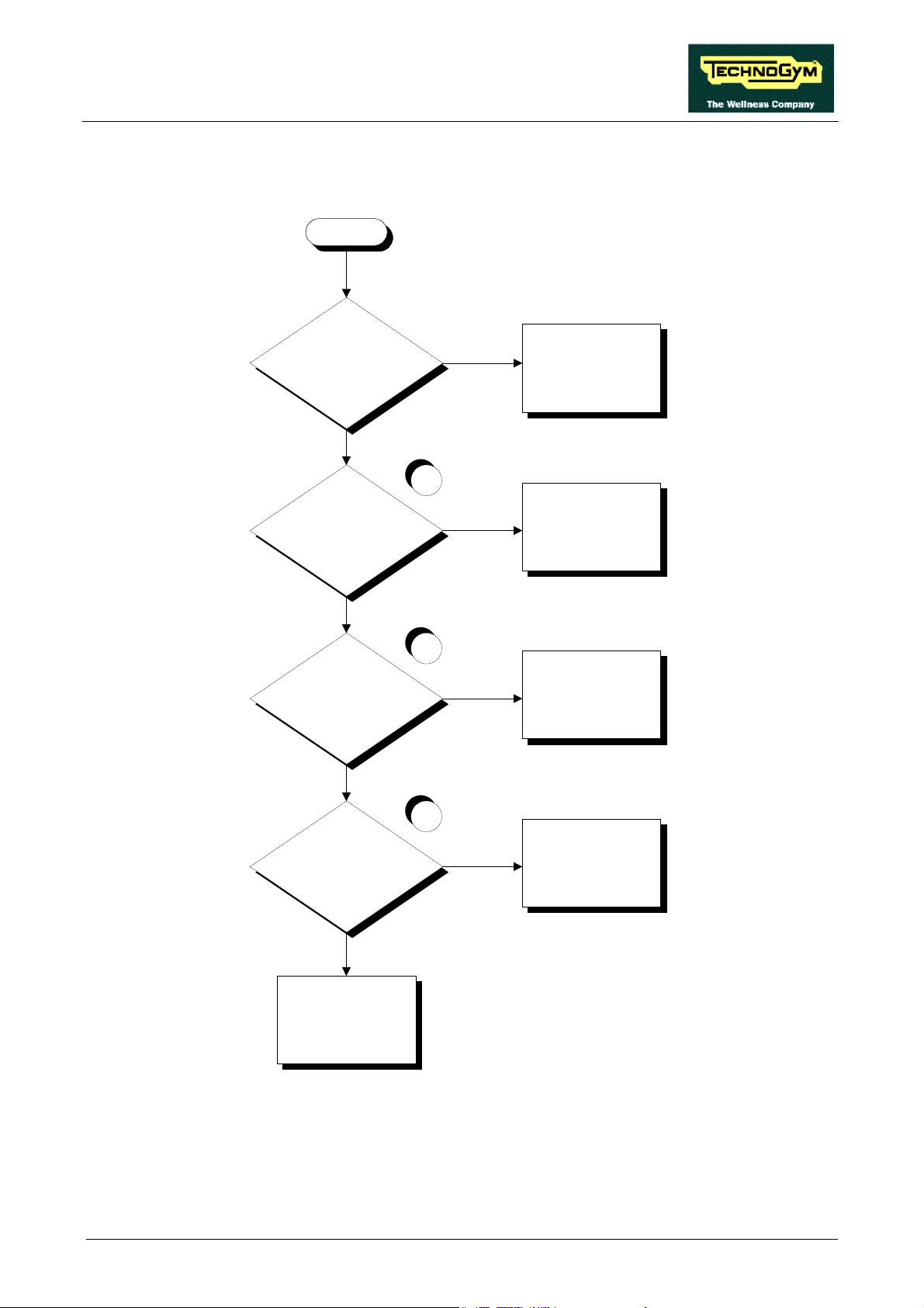
FORMA: Service & Maintenance manual - rev. 3.0
6.3.4. T
HE INVERTER DISPLAY SHOWS
E09
This inverter error message is related to low line voltage problems on the inverter power supply.
E09
Does the machine resume
correct operation after being
turned off for 1 minute?
NO
Is the power supply at the
inverter input OK?
NO
Is the supply voltage at the
filter input correct?
YES
YES
Probable low line voltage.
The machine is OK
1
YES
Replace the inverter
2
NO
Check and reinstate the
wiring between the power
input socket, automatic
circuit breaker and filter
3
NO
Is the supply voltage at the
filter output correct?
Replace the filter
YES
Check and reinstate the
wiring between the filter
and inverter
Follow the procedure step by step to correctly diagnose the problem. Take particular care with the
checks highlighted by circled numbers, which are described in detail below:
(1) Place the tester probe between terminals L1 and N on the inverter. The measured value should
be 220 VAC.
Page 6.13
Page 54

FORMA: Service & Maintenance manual - rev. 3.0
(2) Disconnect the filter supply cables and place the tester probes across them. The measured
voltage should be 220 VAC.
(3) Disconnect the filter output cables and place the tester probes across the filter terminals. The
measured voltage should be 220 VAC.
This error may be generated even by brief drops in the line voltage due to overloads or
other causes. Therefore, it can be very useful to check the value of the mains voltage
recorded in the inverter memory at the time when the error occurred. To obtain the
mains voltage, the displayed value must be divided by 0.141 .
Page 6.14
Page 55

FORMA: Service & Maintenance manual - rev. 3.0
6.3.5. T
HE INVERTER DISPLAY SHOWS
E12
This inverter error message is related to the opening of the motor thermal cutouts.
E12
YES
Does the machine resume
correct operation after being
turned off for 1 hour?
NO
1
NO
Is the thermal cutout on the
motor OK?
Probable overheating of
the motor. The machine is
OK
Replace the belt motor
YES
2
Is the wiring between the
motor thermal cutout and
the inverter correct?
NO
Replace cable FR-7 or
FR-8
YES
3
Replace the inverter
YES
Does the error persist
after disconnecting the
motor thermal cutout
cables from the inverter
input?
NO
Programming error on the
inverter. Reprogram it.
Follow the procedure step by step to correctly diagnose the problem. Take particular care with the
checks highlighted by circled numbers, which are described in detail below:
(1) Disconnect the motor thermal cutout cables from the inverter and place the tester probes
across them. The measured resistance should be less than 1 Ohm.
In some cases the value may be higher due to oxidation of the contacts. To reinstate
correct operation, it is necessary to perform a special operation which will be described
to you on contacting the Technogym Service.
Page 6.15
Page 56

FORMA: Service & Maintenance manual - rev. 3.0
(2) Disconnect the motor thermal cutout cable from both the motor and the inverter, and place the
tester probes across the ends of each wire. The measured resistance should be 0 Ohm.
(3) Disconnect the motor thermal cutout from the inverter: pin P24 and 3.
Page 6.16
Page 57

FORMA: Service & Maintenance manual - rev. 3.0
6.3.6. T
HE INVERTER DISPLAY SHOWS
E14
This inverter error message is related to poor isolation between the motor phases and ground.
E14
1
Are the motor phases
isolated from ground at the
inverter output?
YES
Are the motor phases
isolated from ground?
YES
Check and reinstate cable
FR-8
NO
Replace the inverter
2
NO
Replace the belt motor
Follow the procedure step by step to correctly diagnose the problem. Take particular care with the
checks highlighted by circled numbers, which are described in detail below:
(1) Disconnect the motor cable from the inverter and place the tester probes between terminals U,
V and W of the inverter and the earth screw (PE). The measured resistance should be in the
order of MOhms or higher.
(2) Disconnect the motor cable from the motor and place a tester between its terminals U, V and
W and ground. The measured resistance should be in the order of MOhms or higher.
Page 6.17
Page 58

FORMA: Service & Maintenance manual - rev. 3.0
6.3.7. T
HE INVERTER DISPLAY SHOWS
E15
This inverter error message is caused by high voltage problems on the inverter power supply line.
E15
Does the machine resume
correct operation after being
switched off for 1 minute?
NO
Is the supply voltage at the
input to the inverter correct?
NO
Is the supply voltage at the
input to the filter correct?
YES
YES
Probable high line voltage.
The machine is OK.
1
YES
Replace the inverter
2
NO
Check and reinstate cable
FR-1/A
3
NO
Is the supply voltage at the
output of the filter correct?
Replace the filter
YES
Check and reinstate cables
FR-2 and FR-4
Follow the procedure step by step to correctly diagnose the problem. Take particular care with the
checks highlighted by circled numbers, which are described in detail below:
(1) Insert the tester probes between terminals L1 and N of the inverter. The measured voltage
should be 220 VAC.
Page 6.18
Page 59

FORMA: Service & Maintenance manual - rev. 3.0
(2) Disconnect the supply cables from the filter and place the tester probes across them. The
measured voltage should be 220 VAC.
(3) Disconnect the filter output cables and place the tester probes across the filter terminals. The
measured voltage should be 220 VAC.
This error may be generated even by brief drops in the line voltage due to overloads or
other causes. Therefore, it can be very useful to check the value of the mains voltage
recorded in the inverter memory at the time when the error occurred. To obtain the
mains voltage, the displayed value must be divided by 0.141.
Page 6.19
Page 60

FORMA: Service & Maintenance manual - rev. 3.0
6.3.8. T
HE INVERTER DISPLAY SHOWS
E21
This inverter error message is associated with problems of high inverter temperature.
E21
YES
Probable overheating of
the inverter. The machine
is OK.
Replace the inverter
NO
Does the machine resume
correct operation after being
switched off for 1 hour?
Page 6.20
Page 61

FORMA: Service & Maintenance manual - rev. 3.0
6.3.9. T
HE INVERTER DISPLAY DOES NOT SHOW ANY ERROR
This is an anomalous error condition in which the machine display reports an error but the inverter
has not generated an error.
No error displayed
1
Is there an alarm signal
asserted at the inverter
output?
NO
Is there an alarm signal
asserted at the input to the
driver board?
NO
Is there an alarm signal
asserted at the output of the
driver board?
NO
YES
Replace the inverter
2
YES
Check and/or replace cable
FR-7
3
YES
Replace the driver
interface board
4
Is there an alarm on trailing
connector CN28?
YES
Check and/or replace cable
FR-12
NO
5
YES
Check and/or replace cable
FR-11
Replace the CPU board
NO
Is there an alarm asserted
at the input to the display?
Follow the procedure step by step to correctly diagnose the problem. Take particular care with the
checks highlighted by circled numbers, which are described in detail below:
Page 6.21
Page 62

FORMA: Service & Maintenance manual - rev. 3.0
(1) Place the tester probes between terminals AL1 and AL0 of the inverter. The measured voltage
should be 5 Vdc in the alarm condition, and 0 Vdc in normal conditions.
(2) As for step (1), but between pins 3 (signal) and 4 (ground) of connector J5 on the driver board.
(3) As for step (1) but between pins 8 (signal) and 12 (ground) of connector J6 on the driver
board.
(4) As for step (1) but between pins 11 (signal) and 12 (ground) of portable connector CN28.
(5) As for step (1) but between pins 8 (signal) and 12 (ground) of connector K4 on the CPU
board.
Page 6.22
Page 63

FORMA: Service & Maintenance manual - rev. 3.0
6.4. THE BELT MOTOR IS JERKING
The probable cause of this error is a disconnected phase on the motor or inverter output.
THE BELT
MOTOR IS
JERKING
1
Are the belt motor windings
short-circuited or
open-circuited?
NO
Does the inverter generate
a balanced voltage on all
phases?
YES
Replace the belt motor
2
NO
Replace the inverter
YES
Check and/or replace
cable FR-8
Follow the procedure step by step to correctly diagnose the problem. Take particular care with the
checks highlighted by circled numbers, which are described in detail below:
(1) Disconnect the motor cable from the motor and place a tester across its terminals U-V, U-W
and V-W. The measured resistance should be approximately 4.4 Ohm.
(2) Operate the machine at 8.3 Km/h and place a tester across its terminals U-V, U-W and V-W.
The measured voltage should be 220 VAC.
Page 6.23
Page 64

FORMA: Service & Maintenance manual - rev. 3.0
6.5. THE BELT MOTOR STARTS WITH DELAY
The problem is caused by the inverter failing to receive the enable signal (Start) or the speed signal.
THE BELT MOTOR
DOES NOT START OR
STARTS WITH DELAY
1
NO
Replace the CPU board
NO
Replace the driver board
Replace the inverter
YES
Are the Start and PW M
signals correct at the
output of the CPU board?
YES
2
Are the Start signal and the
analog speed reference
signal correct at the output
of the driver board?
Follow the procedure step by step to correctly diagnose the problem. Take particular care with the
checks highlighted by circled numbers, which are described in detail below:
(1) To check the Start signal, place a tester between pins 6 (signal) and 12 (ground) of connector
K4 on the CPU board. The measured voltage should be 0.2 Vdc when the tread-belt is
stopped, and 4.8 Vdc immediately after pressing the “Start” key.
To check the PWM signal, place a tester between pins 4 (signal) and 12 (ground) of connector
K4 on the CPU board. The measured voltage should be 5 Vdc when the tread-belt is stopped,
whereas immediately after pressing the “Start” key the reading should rapidly decrease until it
reaches a fixed value corresponding to the selected speed. The variation of the signal should
be accompanied by a corresponding variation in the tread-belt speed: see Table 6.6-1 or Table
6.6-2 depending on whether the machine is a Forma 2 or a Forma 3.
(2) To check the Start signal, place a tester between pin 2 (signal) and 1 (ground) of connector J5
on the driver board. When the tread-belt is stopped the reading should be -23.8 Vdc, and
immediately after pressing the “Start” key it should be 0 Vdc.
To check analog speed reference signal, place a tester between pin 5 (signal) and 6 (ground) of
connector J5 on the driver board. When the tread-belt is stopped the reading should be 0 Vdc,
and immediately after pressing the “Start” key the value should increase rapidly to reach a
fixed value corresponding to the selected speed. The variation of the signal should be
accompanied by a corresponding variation in the tread-belt speed: see Table 6.6-1 or Table
6.6-2 depending on whether the machine is a Forma 2 or a Forma 3.
Page 6.24
Page 65

FORMA: Service & Maintenance manual - rev. 3.0
6.6. THE DISPLAYED SPEED IS INCORRECT
The machine displays this error if:
• the calibration is incorrect;
• there are HW problems with the CPU board – driver board – inverter and motor group.
THE DISPLAYED SPEED IS
INCORRECT
Check the inverter
parameters setting and
regulate the speed
Is the relationship between
the displayed speed and the
inverter frequency correct?
NO
Is the inverter control
voltage correct?
NO
1
2
YES
The machine is operating
correctly
3
YES
Replace the inverter
4
Is the inverter control
voltage at the output of the
inverter interface board
correct?
NO
Is the inverter control PWM
signal at the input of the
inverter interface board
correct?
NO
A
YES
Check and/or replace
cable FR-7
5
YES
Replace the inverter
interface board
Page 6.25
Page 66

FORMA: Service & Maintenance manual - rev. 3.0
A
6
YES
Check and/or replace
cables RN-1 and/or RN-2
Replace the CPU board
NO
Is the inverter control PWM
signal at the output of the
CPU board correct?
Follow the procedure step by step to correctly diagnose the problem. Take particular care with the
checks highlighted by circled numbers, which are described in detail below:
(1) See paragraph 9.5. to set the inverter and 8.6. to regulate the speed.
(2) When the machine is in operation, check that the speed shown on the display and the inverter
operating frequency are approximately those shown in the tables below, depending on whether
the machine is a Forma 2 or a Forma 3.
• Forma 2:
SPEED
(Km/h)
PWM SIGNAL
(Vdc)
ANALOG SIGNAL
(Vdc)
FREQUENCY
(Hz)
CPU BOARD DRIVER BOARD INVERTER
DISPLAY 4-12/K4 4-12/J6 5-6/J5 O-L DISPLAY
1.0 4.65 4.65 0.52 0.52 5.4
4.0 3.80 3.80 2.29 2.29 23.7
8.0 2.67 2.67 4.67 4.67 48.0
12.0 1.54 1.54 7.05 7.05 72.4
16.0 0.42 0.42 9.42 9.42 97
• Forma 3:
DISPLAY 4-12/K4 4-12/J6 5-6/J5 O-L DISPLAY
Page 6.26
Table 6.6-1
SPEED
(Km/h)
PWM SIGNAL
(Vdc)
ANALOG SIGNAL
(Vdc)
FREQUENCY
(Hz)
CPU BOARD DRIVER BOARD INVERTER
1.0 4.73 4.73 0.52 0.52 4.2
4.0 4.06 4.06 2.4 2.4 19.5
8.0 3.17 3.17 4.89 4.89 40
12.0 2.27 2.27 7.4 7.4 60.2
16.0 1.38 1.38 9.9 9.9 80
Table 6.6-2
Page 67

FORMA: Service & Maintenance manual - rev. 3.0
(3) Place the tester probes between the 0 (signal) and L (ground) terminals of the inverter. Check
that during machine operation the speed shown on the display and the voltage measured on
the inverter correspond the values shown in Table 6.6-1 or in Table 6.6-2.
(4) Place the tester probes between pins 5 (signal) and 6 (ground) of connector J5 on the driver
board. Check that during machine operation the speed shown on the display and the voltage
measured on the inverter correspond the values shown in Table 6.6-1 or in Table 6.6-2.
(5) Place the tester probes between pins 4 (signal) and 12 (ground) of connector J6 on the driver
board. Check that during machine operation the speed shown on the display and the voltage
measured on the inverter correspond the values shown in Table 6.6-1 or in Table 6.6-2.
(6) Place the tester probes between pins 4 (signal) and 12 (ground) of connector K4 on the CPU
board. Check that during machine operation the speed shown on the display and the voltage
measured on the inverter correspond the values shown in Table 6.6-1 or in Table 6.6-2.
Page 6.27
Page 68

FORMA: Service & Maintenance manual - rev. 3.0
6.7. THE DISPLAY SHOWS “E 5”
The machine displays this error if:.
• it receives an up-down motor alarm signal from the driver board;
• it fails to receive an encoder feedback signal after having actuated the motor.
THE DISPLAY SHOWS "E5"
1
Does the CPU board send the
correct drive signal?
YES
Does the correct drive signal
reach trailing connector CN28?
YES
Dose the driver board receive the
correct drive signal?
YES
NO
Replace the CPU board
2
NO
Check and/or replace
cable FR-11
3
NO
Check and/or replace
cable FR-12
4
Do the relays on the driver board
commutate correctly?
Continued on the following page.
Page 6.28
NO
Replace the relays on the
driver board
YES
A
Page 69

FORMA: Service & Maintenance manual - rev. 3.0
A
5
Does the driver board send the
drive voltage to up-down motor?
YES
Is there an alarm signal asserted
at the output of the driver board?
NO
Does the encoder signal reach
the input of the driver board?
NO
Replace the driver board
6
YES
B
7
YES
C
Replace the up-down
motor
NO
Replace the up-down motor
Continued on the following page.
NO
B
Does the motor draw the
correct current?
8
YES
Adjust the current limiter on the
driver board and/or replace the
driver board
Page 6.29
Page 70

FORMA: Service & Maintenance manual - rev. 3.0
C
9
Replace the CPU board
YES
Does the encoder signal reach
the output of the driver board?
YES
Does the encoder signal reach
trailing connector CN28
YES
Does the encoder signal reach
the input of the CPU board?
NO
Replace the driver board
10
NO
Replace cable FR-12
11
NO
Replace cable FR-11
Follow the procedure step by step to correctly diagnose the problem. Take particular care with the
checks highlighted by circled numbers, which are described in detail below:
(1) Place the tester probes between pins 5 (signal) and 12 (ground) of connector K4 on the CPU
board. Press the “↑” key: the measured voltage should be approximately 4.65 Vdc. Place the
tester probes between pins 3 (signal) and 12 (ground) of connector K4 on the CPU board.
Press the “↓” key: the measured voltage should be approximately 4.65 Vdc.
(2) Place the tester probes between pins 2 (signal) and 12 (ground) of portable connector CN28.
Press the “↑” key: the measured voltage should be approximately 4.65 Vdc. Place the tester
probes between pins 1 (signal) and 12 (ground) of portable connector CN28. Press the “↓”
key: the measured voltage should be approximately 4.65 Vdc.
(3) Place the tester probes between pins 5 (signal) and 12 (ground) of connector J6 on the driver
board. Press the “↑” key: the measured voltage should be approximately 4.65 Vdc. Place the
tester probes between pins 3 (signal) and 12 (ground) on connector J6 of the driver board.
Press the “↓” key: the measured voltage should be approximately 4.65 Vdc.
Page 6.30
Page 71

FORMA: Service & Maintenance manual - rev. 3.0
(4) Check for the click of the relay.
(5) Place the tester probes between pins 1 and 2 of connector J1 on the driver board. Press the “↑”
or “↓” key: the absolute measured value should be approximately 20 Vdc.
(6) Place the tester probes between pin 7 (signal) and 12 (ground) of connector J6 on the driver
board. The measured value should be approximately 0 Vdc if the circuit board has detected an
alarm condition.
(7) Place the tester probes between pins 5 (signal) and 6 (ground) of connector J1 on the driver
board. There should be a square wave signal alternating between 8.8 and 11.4 Vdc. Using a
tester, the reading should be approximately 10 Vdc.
(8) Place the tester probes in series with the motor cable. Press the “↑” or “↓” keys: the steady-
state measured value should be less than 4-5 A.
(9) Place the tester probes between pins 9 (signal) and 11 (ground) of connector J6 on the driver
board. There should be a square wave signal alternating between 0 and 5 Vdc. Using a tester,
the reading should be 2.5 Vdc.
(10) Place the tester probes between pins 4 (signal) and 5 (ground) of portable connector CN28.
There should be a square wave signal varying alternating 0 and 5 Vdc. Using a tester, the
reading should be approximately 2.5 Vdc.
(11) Place the tester probes between pins 9 (signal) and 11 (ground) of connector K4 on the CPU
board. There should be a square wave signal alternating between 0 an 5 Vdc. Using a tester,
the reading should be approximately 2.5 Vdc.
Page 6.31
Page 72

FORMA: Service & Maintenance manual - rev. 3.0
6.8. THE UP-DOWN MOVES IN ONLY ONE DIRECTION
The machine displays this error if:
• a relay on the driver board is defective;
• the CPU board fails to send the enable signal;
• the driver board is not able to drive the motor.
THE UP-DOWN MOTOR
MOVES IN ONE
DIRECTION ONLY
1
Does the CPU board send the
correct control signal in the inactive
direction?
YES
Does the correct control signal for
the inactive direction reach trailing
connector CN28?
YES
VDoes the driver board receive the
correct control signal in the inactive
direction?
NO
Replace the CPU board
2
NO
Check and/or replace
cable FR-11
3
NO
Check and/or replace
cable FR-12
Replace the faulty relays
Page 6.32
NO
YES
Are the relays on the driver board in
good condition?
4
YES
Replace the driver board
Page 73

FORMA: Service & Maintenance manual - rev. 3.0
Follow the procedure step by step to correctly diagnose the problem. Take particular care with the
checks highlighted by circled numbers, which are described in detail below:
(1) Place the tester probes between pins 5 (signal) and 12 (ground) of connector K4 on the CPU
board. Press the “↑” key: the measured value should be 4.65 Vdc. Place the tester probes
between pins 3 (signal) and 12 (ground) of connector K4 on the CPU board. Press the “↓”
key: the measured value should be approximately 4.65 Vdc.
(2) Place the tester probes between pins 2 (signal) and 12 (ground) of portable connector CN28.
Press the “↑” key: the measured value should be approximately 4.65 Vdc. Place the tester
probes between pins 1 (signal) and 12 (ground) of portable connector CN28. Press the “↓”
key: the measured value should be approximately 4.65 Vdc.
(3) Place the tester probes between pins 5 (signal) and 12 (ground) of connector J6 on the driver
board. Press the “↑” key: the measured voltage should be 4.65 Vdc. Place the tester probes
between pins 3 (signal) and 12 (ground) of connector J6 on the driver board. Press the “↓”
key: the measured value should be approximately 4.65 Vdc.
(4) Check that there are no visible scorch marks, and that the travel of the moving parts is not
obstructed.
Page 6.33
Page 74

FORMA: Service & Maintenance manual - rev. 3.0
6.9. THE DISPLAYED ELEVATION IS INCORRECT
The machine displays this error if:
• the reset procedure detects an incorrect reference;
• the encoder signal is incorrect due to a bad reading or noise.
THE DISPLAYED
ELEVATION IS
INCORRECT
NO
Does the machine correctly
complete the reset procedure?
A
YES
Replace the CPU bo
Continued on the following page.
YES
Do the encoder signals at the
input and output of the driver
board have the same frequency?
YES
Do the encoder signals at the
output of the driver board and at
the input to the CPU board
have the same frequency?
1
NO
Replace the driver board
2
NO
Replace cables FR-11
and/or FR-12
Page 6.34
Page 75

FORMA: Service & Maintenance manual - rev. 3.0
A
YES
Remove the obstruction
3
NO
Replace the up-down
motor
Adjust the current limiter
on the driver board and/or
replace the driver board
Is there something obstructing
the movement of the machine?
NO
YES
Does the motor draw the correct
current?
Follow the procedure step by step to correctly diagnose the problem. Take particular care with the
checks highlighted by circled numbers, which are described in detail below:
(1) To measure the encoder signal input to the driver board, place the tester probes between pins 5
(signal) and 6 (ground) of connector J1. To measure the encoder signal output by the driver
board, place the tester probes between pins 9 (signal) and 11 (ground) of connector J6.
(2) To measure the encoder signal output by the driver board, place the tester probes between pins
9 (signal) and 11 (ground) of connector J6. To measure the encoder signal input to the CPU
board, place the tester probes between pins 9 (signal) and 11 (ground) of connector K4.
(3) Place the tester probes in series with the motor cable. Press the “↑” or “↓” key: the steady-
state measured value should be less than 4÷5 A.
Page 6.35
Page 76

FORMA: Service & Maintenance manual - rev. 3.0
6.10. THE FAN IS NOT WORKING
This problem occurs when the supply voltage fails to reach the fan.
THE FAN DOES
NOT WORK
1
Does the c orrect supply v olt age
reach c onnect or CN 2 on the f an
interf ace board?
SI
When t he motor is running, does
the inv erter output the enable f an
signal?
SI
Does the enable s ignal reac h the
f an int erf ace board?
NO
Replac e cable FR-1/A
SI
2 3
NO
Chec k the programming of the
inverter. Is it correct?
NO
4
NO
Chec k/ replace c able
FR-17
Replac e the Inv ert er
Reprogram the inv erter
SI
A
Segue nella pagina successiva.
Page 6.36
Page 77

FORMA: Service & Maintenance manual - rev. 3.0
A
5
Is the supply voltage correct at
the output of the f an interf ace
board?
SI
Is the supply voltage correct at
the input to t he f an?
SI
Replac e the f an
NO
6
NO
Replac e the f an
interf ace board
Chec k/ replace c able FR
-16
Segui la guida passo a passo per una corretta diagnosi del guasto. In particolare presta attenzione
all’esecuzione dei controlli evidenziati dalle caselle numerate e qui di seguito dettagliati:
(1) Place the tester probes across the IN pins of connector CN2, check that the supply voltage is
correct: the measured value should be 220 VAC.
(2) Place the tester probes across pins CM2 and L of the inverter terminal block and check the
value of the enable fan signal: the measured voltage should be 24.55 Vdc.
(3) Check that the inverter parameters are correctly configured according to the procedure 9.5.
“Programming the HITACHI SJ100 inverter”.
WARNING: incorrect programming of the inverter can cause serious damage to
the machine or malfunctioning that is potentially hazardous to the user. Therefore,
attempt this operation only if certain of being able to carry out the procedure with
the latest SW version.
(4) Place the tester probes across pins 1 and 2 of connector CN1 on the component interface
board and check the value of the enable fan signal: the measured voltage should be 24.55 Vdc.
Page 6.37
Page 78

FORMA: Service & Maintenance manual - rev. 3.0
(5) As for point (1) but across the OUT pins of connector CN2.
(6) Check the supply voltage across the Faston terminals at the input to the fan: the measured
value should be 220 VAC.
Page 6.38
Page 79

FORMA: Service & Maintenance manual - rev. 3.0
6.11. THERE IS NO HEART RATE SIGNAL
The machine displays this error if the receiver is not working or if it is not supplied by the CPU
board.
THERE IS NO
CARDIO SIGNAL
1
Is the supply voltage on the
receiver connector correct?
NO
Is the supply voltage on
connector K7 of the CPU board
correct.
NO
Replace the display CPU
board
YES
Replace the receiver
2
YES
Replace or repair cable
RL-14
Follow the procedure step by step to correctly diagnose the problem. Take particular care with the
checks highlighted by circled numbers, which are described in detail below:
(7) Place the tester probes between pins 1 (signal) and 3 (ground) (the red and black wires) of the
4-pin receiver connector: the measured value should be +5Vdc.
(8) Place the tester probes between pins 1 (signal) and 3 (ground) (the red and black wires) of
connector K7 on the CPU board of the display: the measured value should be +5Vdc.
Page 6.39
Page 80

FORMA: Service & Maintenance manual - rev. 3.0
6.12. THE HEART RATE SIGNAL IS INCORRECT
The machine displays this error if the receiver is disturbed by electromagnetic noise.
THE HEART RATE
SIGNAL IS
INCORRECT
Is the minimum distance
between machines OK?
YES
Is the receiver positioned
correctly, and are the
connecting cables correctly
routed?
YES
If the TGS is present, is the
RL-20 cable correctly routed?
NO
Move the machines to
the minimum distance:
see paragraph 5.1.
NO
Position the receiver and
the cable correctly: see
paragraph 11.1
NO
Correctly route the cable:
see paragraph 11.1.
Are there sources of
electromagnetic noise near
Continued on the following page.
Page 6.40
YES
the receiver?
NO
A
1
Move the machine away
YES
from the electromagnetic
source or attenuate the
power of the noise: see
paragraph 11.1.
Page 81

FORMA: Service & Maintenance manual - rev. 3.0
A
2
Is the transmitter in good
working order?
YES
Is the transmitter always
within a distance of 80 cm
from the receiver?
YES
Change the receiver
NO
NO
Use a known good
transmitter
Keep the transmitter
within the minimum
reception distance
Follow the procedure step by step to correctly diagnose the problem. Take particular care with the
checks highlighted by circled numbers, which are described in detail below:
(1) To check for electromagnetic noise near the machine, use a frequency signal monitor
constructed as shown in the schematic below:
The circuit lights the LED for every heart beat and/or disturbance that is received: in this way
it possible to determine whether there is any interference, and identify its sources.
(2) Check the battery power level, using a tester if possible. Otherwise use a receiver or another
“reference” machine to check operation up to a distance of about 80 cm from the receiver.
ATTENTION: Consult paragraph 11.1. “Technical notes on cardio receivers”.
Page 6.41
Page 82

FORMA: Service & Maintenance manual - rev. 3.0
Page intentionally left blank
Page 6.42
Page 83

FORMA: Service & Maintenance manual - rev. 3.0
7. DISASSEMBLY OF COMPONENTS
7.1. DISASSEMBLING THE DISPLAY
1. Turn off the machine and unplug the mains
lead from the wall outlet.
2. Back off the 4 screws a using a phillips
screwdriver.
3. Unplug the cable connector.
4. Remove the DISPLAY.
To reassemble the DISPLAY, carry out the
above steps in reverse order.
Figure 7.1-1
Page 7.1
Page 84

FORMA: Service & Maintenance manual - rev. 3.0
7.2. DISASSEMBLING THE EPROM
Carry out the procedure described in paragraph
7.1. “Disassembling the display”.
With the display placed on a work bench:
1. Remove EPROM a from its socket, using an
IC extractor tool.
Figure 7.2-1
To reassemble the EPROM:
1. Insert the EPROM pins into the socket
starting from the top, so that the lower holes
of the socket remain free.
2. Make that the reference index b on the
EPROM coincides with the reference notch c
on its socket.
3. Be careful to position the EPROM pins
directly above the holes on the socket.
4. Push the pins into the socket.
Figure 7.2-2
The EPROM may be irreversibly
damaged if its reference index is not
correctly matched up with the notch on
the socket, or if its pins are bent.
ATTENTION: The EPROM SW versions used on Forma 2 and Forma 3 are different,
due to differences in certain mechanical characteristics between the two machines. In
consequence:
• Forma 2: SW usable up to version 2.1.10;
• Forma 3: SW usable as of version 3.1.02.
Page 7.2
Page 85

FORMA: Service & Maintenance manual - rev. 3.0
7.3. DISASSEMBLING THE DISPLAY BOARDS
Carry out the procedure described in paragraph
7.1. “Disassembling the display”.
With the display placed on a work bench:
1. Unplug connectors a.
2. Remove the 4 fasteners b.
3. Remove the CPU BOARD.
4. Back off the 4 screws c using a medium
phillips screwdriver.
5. Remove the LED BOARD.
To reassemble the circuit boards, carry out the
Figure 7.3-1
above steps in reverse order.
Page 7.3
Page 86

FORMA: Service & Maintenance manual - rev. 3.0
7.4. DISASSEMBLING THE KEYBOARD
Carry out the procedure described in paragraph
7.1. “Disassembling the display”.
With the display placed on a work bench:
1. Unplug the KEYBOARD connector a.
Figure 7.4-1
2. Using a pointed tool, lift up and detach a
corner of the KEYBOARD.
To reassemble the new KEYBOARD:
1. Remove backing film from the adhesive side.
2. Apply the adhesive part, starting from the top
and working toward the bottom, being
careful not to bend the KEYBOARD.
3. Insert the connector in the special slot on the
display and connect it to the CPU board.
4. Remove the protective film.
When reassembling the KEYBOARD,
make sure that none of the keys are bent
or remain pushed in.
Figure 7.4-2
The KEYBOARD assembly procedure
can only be performed once, because
disassembly damages the tracks and
keys.
Page 7.4
Page 87

FORMA: Service & Maintenance manual - rev. 3.0
7.5. DISASSEMBLING THE CARDIO RECEIVER
Carry out the procedure described in paragraph
7.1. “Disassembling the display”.
With the display placed on a work bench:
1. Unplug connector a of cable RL-14 from the
CPU board.
2. Remove the strap securing the housing.
3. Remove the RECEIVER.
To reassemble the RECEIVER, carry out the
above steps in reverse order, placing it between
the 2 foam pads.
Figure 7.5-1
Page 7.5
Page 88

FORMA: Service & Maintenance manual - rev. 3.0
7.6. DISASSEMBLING THE SAFETY SWITCH
Carry out the procedure described in paragraph
7.1. “Disassembling the display”.
With the display placed on a work bench:
1. Lift up the sticker a situated underneath the
“Safety switch”;
2. Using a medium phillips screwdriver, back
off the 2 screws under the sticker.
Figure 7.6-1
3. Unplug connector b of cable RL-17.
4. Remove the SAFETY SWITCH c.
To reassemble the SAFETY SWITCH, carry out
the above steps in reverse order.
Figure 7.6-2
Page 7.6
Page 89

FORMA: Service & Maintenance manual - rev. 3.0
7.7. DISASSEMBLING THE MOTOR GUARD
1. Raise the machine to its maximum incline
position.
2. Turn off the machine and unplug the mains
lead from the wall outlet.
3. Take off the fuse holder a.
4. On each side, back off the 2 screws b using a
4-mm hex T wrench.
5. Lift up the rubber guard c, detaching it from
the MOTOR GUARD.
6. Remove the MOTOR GUARD d by lifting it
and rotating it toward the right.
Figure 7.7-1
To reassemble the MOTOR GUARD, carry out
the above steps in reverse order.
Page 7.7
Page 90

FORMA: Service & Maintenance manual - rev. 3.0
7.8. DISASSEMBLING THE REAR ROLLER
Carry out the procedure described in paragraph
7.7. “Disassembling the motor guard”.
On each side of the machine:
1. Back off the 2 screws a using a 2.5-mm hex
T wrench.
2. Slide the footrest guide forward.
Figure 7.8-1
3. Overturn the machine on one side.
4. Back off screw b using a medium phillips
screwdriver.
Figure 7.8-2
Continued on following page →
Page 7.8
Page 91

FORMA: Service & Maintenance manual - rev. 3.0
Figure 7.8-3
5. Return the machine to the upright position.
6. Back off the 2 screws c using a 2.5-mm hex
T wrench.
7. Remove the rear plug d.
To facilitate the subsequent tightening
of the belt, shift the seam to the
underside of the machine and measure
out a distance of 1 m on the belt,
marking its ends with a white felt tip
pen.
8. On the right side, back off the 2 nuts e which
Figure 7.8-4
clamp the roller earth cable.
9. Slacken the belt tension, backing off the 2
screws f using a 6-mm hex T wrench.
10. Pull the REAR ROLLER out of its supports.
11. Remove the REAR ROLLER from the side.
To reassemble the REAR ROLLER, carry out the
above steps in reverse order.
After completing the procedure, adjust
Figure 7.8-5
the tension and centering of the treadbelt as described in paragraphs 8.2. and
8.3. .
Page 7.9
Page 92

FORMA: Service & Maintenance manual - rev. 3.0
7.9. DISASSEMBLING THE MOTOR ROLLER AND DRIVEBELT
Carry out the procedure described in paragraph
7.7. “Disassembling the motor guard”.
1. Slacken the drive-belt tension by turning the
rear roller fixing screws.
To facilitate the subsequent tightening
of the tread-belt, move the seam to the
underside of the machine and measure
out a distance of 1 m on the belt,
marking its ends with a white felt tip
Figure 7.9-1
pen.
2. Overturn the machine on the right side.
3. On each side, back off the screw a using a 6mm hex T wrench.
4. Disengage the drive-belt from the MOTOR
ROLLER.
If it proves difficult to disengage the
DRIVE-BELT, slacken its tension as
described in paragraph 8.5.
Figure 7.9-2
Continued on the following page →
Page 7.10
Page 93

FORMA: Service & Maintenance manual - rev. 3.0
5. Using a felt-tip pen, mark the top part of both
flywheels as shown in the figure.
6. Disassemble the outer flywheel by backing
off the two screws b using a 4-mm Allen
wrench.
7. Remove the DRIVE-BELT from the treadbelt motor pulley.
8. Pull out the MOTOR ROLLER, first from
the right hand support and then from the left
hand support.
9. Remove the MOTOR ROLLER from the left
side.
To reassemble the MOTOR ROLLER and the
DRIVE-BELT, carry out the above steps in
reverse order.
To reassemble the flywheels the right
Figura 7.9-3
way round, use the markings made
previously.
After completing this procedure, adjust
the tension and centering of the treadbelt as described in paragraphs 8.2. and
8.3. and adjust the tension and
alignment of the DRIVE-BELT as
described in paragraph 8.4.
Page 7.11
Page 94

FORMA: Service & Maintenance manual - rev. 3.0
7.10. DISASSEMBLING THE TREAD-BELT AND RUNNING
TRACK
Carry out the procedures described in paragraphs
7.7. “Disassembling the motor guard”, 7.8.
“Disassembling the rear roller” and 7.9.
“Disassembling the motor roller and drive-belt”.
1. Overturn the machine on the right side.
2. Back off the 2 rear screws a using a 5-mm T
wrench.
Figure 7.10-1
3. Remove the RUNNING TRACK and
TREAD-BELT group from the back.
4. Remove the TREAD-BELT from the
RUNNING TRACK.
To separate RUNNING TRACK from the plate
fixing it to the frame:
1. Holding in place the 2 nuts b with a 13-mm
wrench, back off their screws using a 5-mm
hex T wrench.
Figure 7.10-2
Continued on the following page →
Page 7.12
Page 95

FORMA: Service & Maintenance manual - rev. 3.0
To reassemble the TREAD-BELT and the
RUNNING TRACK, carry out the above steps in
reverse order.
When reassembling the TREAD-BELT,
make sure that:
• it is assembled in the direction
indicated by the direction arrow on
the inner side, if one is present;
• it is correctly centered on the
RUNNING TRACK;
• it is not pinched by the RUNNING
TRACK.
Lubricate the RUNNING TRACK
before reassembling it.
To facilitate reassembly of the
RUNNING TRACK on the frame, push
it against the vibration damper so that
the upper pad does not obstruct its
movement.
After completing the procedure, adjust
the tension and centering of the belt as
described in paragraphs 8.2. and 8.3.
and adjust the tension and alignment of
the motor drive-belt as described in
paragraph 8.4. .
Page 7.13
Page 96

FORMA: Service & Maintenance manual - rev. 3.0
7.11. DISASSEMBLING THE SHOCK ABSORBERS
Carry out the procedures described in paragraph
7.10. “Disassembling the tread-belt and running
track”.
1. On each side of the machine, remove the
SHOCK ABSORBERS from the top,
detaching them from the adhesive film.
To reassemble the SHOCK ABSORBERS, carry
out the above steps in reverse order.
Figure 7.11-1
Page 7.14
Page 97

FORMA: Service & Maintenance manual - rev. 3.0
7.12. DISASSEMBLING THE FOOTREST GUIDE
Carry out the procedure described in paragraph
7.7. “Disassembling the motor guard”.
On each side of the machine:
1. Back off the 2 screws a using a 2.5-mm hex
T wrench.
2. Slide the FOOTREST GUIDE forward.
Figure 7.12-1
3. Overturn the machine on one side.
4. Back off the screw b using a medium phillips
screwdriver.
Figure 7.12-2
5. Return the machine to the upright position.
6. Back off the 2 screws c using a 2.5-mm hex
T wrench.
7. Remove the rear plug d.
8. Remove the FOOTREST GUIDE from the
rear side.
If the FOOTRESTS are not securely
fixed, replace the brackets fixing them to
the side guard.
To reassemble the SHOCK ABSORBER, carry
Figure 7.12-3
out the above steps in reverse order.
Page 7.15
Page 98

FORMA: Service & Maintenance manual - rev. 3.0
7.13. DISASSEMBLING THE SIDE GUARDS
Carry out the procedures described in paragraphs
7.7. “Disassembling the motor guard”, 7.8.
“Disassembling the rear roller”, 7.9.
“Disassembling the motor roller and drive-belt”
and 7.10. “Disassembling the tread-belt and
running track”.
To remove a SIDE GUARD:
1. Overturn the machine on the opposite side.
2. Back off the 6 screws a using a large phillips
screwdriver.
3. Remove the SIDE GUARD by pulling it
Figure 7.13-1
toward the back.
To reassemble the SIDE GUARDS, carry out the
above steps in reverse order.
Page 7.16
Page 99

FORMA: Service & Maintenance manual - rev. 3.0
7.14. DISASSEMBLING THE MOTOR GUARD GRILLE
1. Raise the machine to an incline of
approximately 5%.
2. Turn off the machine and unplug the mains
lead from the wall outlet.
3. Overturn the machine on one side.
4. Back off the 2 screws a using a large phillips
screwdriver.
5. Repeat the procedure on the opposite side.
6. Remove the MOTOR GUARD GRILLE by
pulling it out from the side.
Figure 7.14-1
To reassemble the MOTOR GUARD GRILLE,
carry out the above steps in reverse order.
Page 7.17
Page 100

FORMA: Service & Maintenance manual - rev. 3.0
7.15. DISASSEMBLING THE TREAD-BELT MOTOR
Carry out the procedures described in paragraphs
7.7. “Disassembling the motor guard”, 7.14.
“Disassembling the motor guard grille”.
1. Remove the dowel a using a 5-mm hex T
wrench.
2. Loosen the drive-belt by turning the dowel
situated underneath the one previously
removed, using a 5-mm hex T wrench.
3. Using a felt-tip pen, mark the top part of both
flywheels as shown in the figure.
4. Disassemble the outer flywheel d by backing
off the two fixing screws using a 4-mm Allen
wrench.
5. Remove the drive-belt b from the pulley and
the flywheel of the TREAD-BELT MOTOR.
6. Back off the 2 nuts c using a 17-mm wrench
and holding the screw in place with an 8-mm
hex T wrench.
7. Remove the TREAD-BELT MOTOR from
the top.
To reassemble the TREAD-BELT MOTOR,
carry out the above steps in reverse order.
Figure 7.15-1
Page 7.18
Figure 7.15-2
When reassembling the TREAD-BELT
MOTOR, check for the presence of the 2
plastic bushings which ensure its
isolation from earth.
To reassemble the flywheels the right
way round, use the markings made
previously.
After completing the procedure, adjust
the tension and alignment of the motor
drive-belt as described in paragraph 8.4.
 Loading...