


CROSS
PERSONAL
REV. 1.1


The information contained in this manual is intended for QUALIFIED TECHNICIANS who have
completed a specific TECHNOGYM training course and are authorized to perform machine start-
up and adjustment procedures as well as extraordinary maintenance or repairs which require a
thorough knowledge of the machine, its operation, its safety devices and working procedures.
CAREFULLY READ THE INFORMATION CONTAINED IN
THIS MANUAL BEFORE PERFORMING ANY MAINTENANCE
PROCEDURES ON THE MACHINE
DANGEROUS VOLTAGES
PRESENT
NOTE:
The information contained in this document is subject to change without notice.
Technogym does not guarantee this documentation in any way. Technogym shall not be held
responsible for any errors contained in this manual and declines all liability for accidents or
damages resulting from the supply, characteristics or use of this manual.
This document contains proprietary information that is protected by copyright. All rights reserved.
No part of this document may be photocopied, reproduced or translated into another language
without the prior written consent of Technogym.
The Technogym™ trademark is property of Technogym S.p.A.
The Cross Personal™ trademark is property of Technogym S.p.A.


CROSS PERSONAL: Service & maintenance manual - rev. 1.1
Page i
Contents
1. GENERAL NOTICES ............................................................................................................................................. 1.1
1.1. INTRODUCTION ................................................................................................................................................... 1.1
1.2. RECOMMENDATIONS .......................................................................................................................................... 1.1
1.3. GENERAL RULES FOR REPAIR PROCEDURES ........................................................................................................ 1.2
2. TECHNICAL CHARACTERISTICS .................................................................................................................... 2.1
2.1. PRODUCT CODES ................................................................................................................................................. 2.1
2.2. SERIAL NUMBER STRUCTURE ............................................................................................................................. 2.2
2.3. TECHNICAL SPECIFICATION ................................................................................................................................ 2.3
2.4. MECHANICAL CHARACTERISTICS ....................................................................................................................... 2.3
2.5. DIMENSIONS .................................................................................................................................................. 2.4
2.6. PACKING DIMENSIONS EUROPE AND OVERSEAS ............................................................................................. 2.4
2.7. AMBIENT SPECIFICATIONS .................................................................................................................................. 2.5
2.8. CONFORMITY TO REGULATIONS .......................................................................................................................... 2.5
2.9. WIRING DIAGRAMS ............................................................................................................................................. 2.6
2.10. CABLES .............................................................................................................................................................. 2.7
2.10.1. CBQ Cables ............................................................................................................................................ 2.7
2.10.2. WB Cables .............................................................................................................................................. 2.7
2.10.3. CU Cables .............................................................................................................................................. 2.7
3. PRINCIPLES OF OPERATION ............................................................................................................................ 3.1
3.1. BLOCK DIAGRAM ................................................................................................................................................ 3.1
3.2. ELECTRONIC COMPONENTS................................................................................................................................. 3.2
3.2.1. CPU board ............................................................................................................................................. 3.2
3.2.1.1. BackUp battery ............................................................................................................................................................................ 3.2
3.2.2. LCD inverter .......................................................................................................................................... 3.3
3.2.3. Digital/Analog tuner board .................................................................................................................... 3.3
3.2.4. LAN network board (integrated) ............................................................................................................ 3.3
3.2.5. Wireless network board (without cables) ............................................................................................... 3.4
3.2.6. Audio/Video external device connector board ....................................................................................... 3.5
3.2.7. Jack cuffie ............................................................................................................................................... 3.5
3.2.8. Scheda C-Safe (integrata) ...................................................................................................................... 3.5
3.2.9. Porta USB di servizio (integrata) ........................................................................................................... 3.5
3.2.10. Capacitive Touch Screen control board ................................................................................................. 3.5
3.2.11. Power Supply board ............................................................................................................................... 3.5
3.2.12. Secondary ON/OFF switch .................................................................................................................... 3.6
3.2.13. Audio Amplifier board ............................................................................................................................ 3.6
3.2.14. Hand Sensor board ................................................................................................................................ 3.6
3.2.15. Cardio receiver HR ................................................................................................................................ 3.7
3.2.16. iPod docking station ............................................................................................................................... 3.7
3.2.17. Client USB port ...................................................................................................................................... 3.8
3.2.18. Dual TGS reader .................................................................................................................................... 3.8
3.2.19. Brake Board ........................................................................................................................................... 3.8
3.2.20. Electromagnetic brake ........................................................................................................................... 3.9
3.2.21. Speed sensor ........................................................................................................................................... 3.9
3.2.22. Power entry module ............................................................................................................................... 3.9
3.3. BRAKE CONTROL .............................................................................................................................................. 3.10
3.3.1. Mechanics ............................................................................................................................................ 3.10
3.3.2. Controls ................................................................................................................................................ 3.10
3.3.3. The signals involved ............................................................................................................................. 3.12
3.4. AUDIO SIGNAL AND AUDIO OUT CONTROL ........................................................................................................ 3.13
3.4.1. Control ................................................................................................................................................. 3.13
3.4.2. The signals involved ............................................................................................................................. 3.14

CROSS PERSONAL: Service & maintenance manual - rev. 1.1
Page ii
4. ACCESSORIES ....................................................................................................................................................... 4.1
4.1. CARDIO THEATER CONNECTION .......................................................................................................................... 4.1
4.2. MONITOR PLUG FOR C-SAFE PORT ...................................................................................................................... 4.2
5. INSTALLATION INSTRUCTIONS ...................................................................................................................... 5.1
5.1. SPECIFICATIONS AND REQUIREMENTS ................................................................................................................ 5.1
5.2. MOVING THE EQUIPMENT ................................................................................................................................... 5.2
5.3. RECOMMENDED ANTENNA SIGNAL REQUIREMENTS ............................................................................................ 5.3
5.4. INSTALLATION .................................................................................................................................................... 5.3
5.5. FIRST POWER-ON ................................................................................................................................................ 5.3
6. TROUBLESHOOTING .......................................................................................................................................... 6.1
6.1. TROUBLESHOOTING MENU .................................................................................................................................. 6.2
6.2. THE DISPLAY STAYS OFF ..................................................................................................................................... 6.3
6.3. NO AUDIO SOUND ............................................................................................................................................... 6.8
6.4. NO TV PICTURE ................................................................................................................................................ 6.12
6.5. THE TOUCH SCREEN DOES NOT WORK / IT’S NOT CALIBRATED .......................................................................... 6.12
6.6. THE RADIO DOES NOT PLAY .............................................................................................................................. 6.12
6.7. THE IPOD DOES NOT WORK ............................................................................................................................... 6.13
6.8. “THE EQUIPMENT IS LOCKED (COM)” MESSAGE ON DISPLAY ................................................................. 6.15
6.9. THE BRAKE BOARD HAS DETECTED AN ERROR ................................................................................................. 6.16
6.10. THERE IS NO RESISTANCE ................................................................................................................................. 6.19
6.11. THE RESISTANCE IS NOT CORRECT .................................................................................................................... 6.22
6.12. THE SPEED SIGNAL IS NOT CORRECT ................................................................................................................. 6.24
6.13. THE MACHINE DOES NOT READ THE TGS KEY .................................................................................................. 6.26
6.14. THERE IS NO HEART RATE SIGNAL ..................................................................................................................... 6.28
6.14.1. Hand sensor ......................................................................................................................................... 6.28
6.14.2. Chest belt .............................................................................................................................................. 6.32
6.15. THE TELEMETRIC HEART RATE SIGNAL IS INCORRECT ....................................................................................... 6.35
6.15.1. Chest belt .............................................................................................................................................. 6.35
6.15.2. Hand Sensor ......................................................................................................................................... 6.39
7. PART DISASSEMBLY ........................................................................................................................................... 7.1
7.1. DISASSEMBLY OF THE REAR DISPLAY COVER ...................................................................................................... 7.1
7.2. DISMANTLING THE WHOLE DISPLAY ................................................................................................................... 7.2
7.3. DISMANTLING THE TOUCH SCREEN .................................................................................................................... 7.3
7.4. DISMANTLING THE DISPLAY BOARDS ................................................................................................................. 7.4
7.5. DISMANTLING THE SECONDARY ON SWITCH CARD ............................................................................................ 7.5
7.6. DISMANTLING THE FRONT GUARDS .................................................................................................................... 7.6
7.7. DISMANTLING THE AMPLIFIER/SPEAKERS .......................................................................................................... 7.7
7.8. DISMANTLING THE TOTAL LEVERS ..................................................................................................................... 7.8
7.9. DISMANTLING THE TWEETER FROM THE TOTAL LEVER ...................................................................................... 7.9
7.10. DISMANTLING THE PLATFORM LEVER .............................................................................................................. 7.10
7.11. DISMANTLING THE MECHANICS/CRANK ASSEMBLY ......................................................................................... 7.11
7.12. DISMANTLING THE CRANK ASSEMBLY BELT ..................................................................................................... 7.12
7.13. DISASSEMBLY OF THE REAR GUARDS ................................................................................................................ 7.13
7.14. DISMANTLING THE BRAKE BELT ...................................................................................................................... 7.14
7.15. DISMANTLING THE BRAKE BELT PULLEY ......................................................................................................... 7.15
7.16. DISMANTLING THE LOW KIT, POWER CARD, BRAKE AND FLYWHEEL .............................................................. 7.16
8. ADJUSTMENTS ...................................................................................................................................................... 8.1
8.1. MECHANICS/CRANK ASSEMBLY SHAPING .......................................................................................................... 8.1
8.2. BRAKE BELT TENSION ......................................................................................................................................... 8.4
8.3. LEVELLING ......................................................................................................................................................... 8.5
9. EQUIPMENT CONFIGURATION ....................................................................................................................... 9.1
9.1. CONFIG.: VISIO - VISIOWEB USER MENÙ .................................................................................................... 9.1
9.2. SERVICE MENU CONFIG.: VISIO - VISIOWEB .......................................................................................... 9.3

CROSS PERSONAL: Service & maintenance manual - rev. 1.1
Page iii
9.2.1.1. Table of configuration parameters .............................................................................................................................................. 9.4
10. UPDATING THE SW ............................................................................................................................................ 10.1
11. SCHEDULED MAINTENANCE ......................................................................................................................... 11.1
12. APPENDIX ............................................................................................................................................................. 12.1
12.1. MENU PASSWORD TABLE .................................................................................................................................. 12.1
12.2. REQUIRED TOOLS ............................................................................................................................................. 12.2

CROSS PERSONAL: Service & maintenance manual - rev. 1.1
Page iv
Page intentionally left blank.

CROSS PERSONAL: Service & maintenance manual - rev. 1.1
Page 1.1
1. GENERAL NOTICES
1.1. INTRODUCTION
This document is reserved for Technogym Service technicians, and is intended to provide
authorized personnel with the necessary information to correctly carry out r epairs and maintenance.
A thorough knowledge of the technical information contained in this manual is essential for
completing the professional training of the operator.
In order to facilitate consultation, the paragraphs are accompanied by schematic drawings which
illustrate the procedure being described.
This manual contains notices and symbols which have a specific meanings:
WARNING: non observance may result in accident or injury.
ATTENTION: non observance may cause damage to the machine.
Information about the operation in progress.
Observation about the operation in progress.
1.2. RECOMMENDATIONS
Technogym recommends the following steps for planning repair procedures:
• Carefully evaluate the customer’s description of the machine malfunction and ask all the
necessary questions to clarify the symptoms of the problem.
• Clearly diagnose the causes of the problem. This manual provides the fundamental theoretical
basis, which must then be integrated by personal experience and attendance at the training
courses periodically offered by Technogym.
• Rationally plan the repair procedure so as to minimize the downtime necessary for procuring
spare parts, preparing tools, etc.
• Access the component to be repaire d, avoiding any unneces sary operat ions. In this regard it will
be useful to refer to the disassembling sequence described in this manual.

CROSS PERSONAL: Service & maintenance manual - rev. 1.1
Page 1.2
1.3. GENERAL RULES FOR REPAIR PROCEDURES
1. Always mark any parts or positions which may be confused with each other at the time of
reassembly.
2. Use original Technogym spare parts and lubricants of the recommended brands.
3. Use special tools where specified.
4. Consult the Technical Newsletters, which may contain more up-to-date information on adjusts
and maintenance than those contained in this manual.
5. Before starting the repair procedure, make sure that the recommended tools are available and in
good condition.
6. For the procedures described in this manual, use only the specified tools.
The tool sizes quoted in this manual are expressed in mm.

CROSS PERSONAL: Service & maintenance manual - rev. 1.1
Page 2.1
2. TECHNICAL CHARACTERISTICS
2.1. PRODUCT CODES
The machine codes take into account all the possible variants and options available for the products.
The machine code, which does not include the Serial Number, consists of 16 alphanumeric characters
arranged as follows:
Characters
Description
key to values
1, 2, 3,
Machine type
D94 = Run Personal
4,
Model
7 = 700
5,
Power supply type
3 = Powered
6,
Display type
Y = VISIOWEB
7,
Accessories
F = Full
8, 9,
Colour of the frame
00 = None
10, 11,
Colour of the upholstery
00 = None
12,
Colour of the guards
R = Renault Grey
13,
TV standard receiver
C = DVB-T
A = ATSC
I = ISDB-T
14, 15,
Language
00 = Multilanguage
16.
Type of packaging.
A, B, C, D, E, F, G, H, I, J, K, S, U
See the following table.
For example, a possible product code would be:
D9573YF0000RD00E
all of the machines will be shipped with the specific power cable for the destination
country. In particular this means a cable with the standard plug used in the
installation country.

CROSS PERSONAL: Service & maintenance manual - rev. 1.1
Page 2.2
This implementation also means a change in the product code. Specifically the last character of the
product code will be characterised based on the options shown in the table below:
16th Character
Product code
Main country
of use
Plug standard
Type of
packaging
A
Australia
A S/NZS 3112
Overseas
B
Brazil
NBR 14136
Overseas
C
China
CPC S-CCC
Overseas
D
South Africa
SANS 164-2
Overseas
E
Europe (EC)
EEC 7/16
European
F
USA (UL 250 V)
NEMA 5-15/
NEMA 5-20
Overseas
G
Great Britain
BS1363
European
H
Argentina
IRAM 2073
Overseas
I
Italy
EEC 7/16
Italy
J
Japan
JIS 8303
Overseas
K
Great Britain
BS1363
Overseas
S
Europe (EC)
EEC 7/16
Overseas
U
USA (UL 110 V)
NEMA 6-15/ NEMA 6-20
Overseas
As shown in the table above, the 16th characte r also identifies the type of packaging depending on
the destination country, i.e. D9573YF0000RD00E.
2.2. SERIAL NUMBER STRUCTURE
The Serial Number, consists of 14 alphanumeric characters arranged as follows:
Characters
Description
key to values
1,2,3,4,5,6,
Product type,
D957 = Cross Personal
3 =Powered
Y = VISIO WEB
7,8,
Year of production,
13 = 2013
9,10,11,12,13,14.
Progressive.
000001
For example, a possible product code would be:
D9573Y13000001

CROSS PERSONAL: Service & maintenance manual - rev. 1.1
Page 2.3
2.3. TECHNICAL SPECIFICATION
SPECIFICATIONS & PERFORMANCE
Power Supply
100-240 VAC – 50-60 Hz
Energy Consumption
160VA
Stand-By Consumption
47,9 Watt (97 VA)
Resistance
56-436 Watt ±10% (at 70 RPM)
Difficulty Level
1-25
Max user weight
160 Kg – 353 Lbs
Fast Track Control
SI
HR monitoring:
Hand sensor, Telemetria
Goal oriented display
YES
Wellness System:
YES
Total Number of
Programs
23
Quick-Start, Goal (Time, Distance, Calories), CPR, Profiles (6
predefined + 12 customizable), Custom, Training Zone, Weight Loss)
Sub-maximal Test:
Fitness test
Available Language
13
Italian, UK English, USA English, German, Spanish, French, Dutch,
Portuguese, Japanese, Chinese, Russian, Turkish, Danish
2.4. MECHANICAL CHARACTERISTICS
MECHANICAL CHARACTERISTICS
Length (mm – in)
1938 mm – 76”
Width (mm – in)
685 mm – 28”
Height (mm – in)
1756 mm – 69”
Weight (Kg – lbs)
145 Kg – 320 lbs

CROSS PERSONAL: Service & maintenance manual - rev. 1.1
Page 2.4
2.5. DIMENSIONS
2.6. PACKING DIMENSIONS EUROPE AND OVERSEAS

CROSS PERSONAL: Service & maintenance manual - rev. 1.1
Page 2.5
2.7. AMBIENT SPECIFICATIONS
Temperature
Operating
from 10° to 25° C
Storage
from -10 to 70° C
Humidity
Operating
from 20% to 90% non-condensing
Storage
from 20% to 90% non-condensing
2.8. CONFORMITY TO REGULATIONS
EUROPE
USA
EMI regulations
EN61000-6-1 (2007)
EN61000-6-3 (2007)
EN61000-3-2 (2007)
EN61000-3-3 (2009)
-
Electrical safety
regulations
EN 60335-1 (2008)
UL 1647
FCC 15
Mechanical safety
regulations
EN957-1 (2006)
EN957-6 (2003)
-
Directives
2006/42/CE
2004/108/CE
2006/95/CE
-
Moreover:
Electrical isolation class: Class I;
Protection rating: IP20.

CROSS PERSONAL: Service & maintenance manual - rev. 1.1
Page 2.6
2.9. WIRING DIAGRAMS

CROSS PERSONAL: Service & maintenance manual - rev. 1.1
Page 2.7
2.10. CABLES
The colour of the cables can be changed, refer in particular to the Pin Out.
2.10.1. CBQ CABLES
CBQ32: TGS cable
(Patch conn.– CPU Board)
CPU Board
CN19
Signal Colour Patch conn.
1
+12 Vdc power supply
Red 8 3
Rx
Brown 1 5
Tx
Blue 2 9
Gnd
Black
6
2.10.2. WB CABLES
WB657: Flat Tuner Board cable
(CPU Board –TUNER Board)
CPU Board
J9
Signal
TUNER Board
J13
1
Capacitive Signal
flat
…50
Capacitive Signal
flat
2.10.3. CU CABLES
CU132: TGS signal cable
(Patch conn. –TGS Dual reader)
Patch conn. Signal Colour
TGS Dual reader
CN1
8
+12Vdc power supply
Black
2
1
RX
Green 1 2
TX
Black 4 6
GND
Black
5

CROSS PERSONAL: Service & maintenance manual - rev. 1.1
Page 2.8
CU331: iPod signal cable
(CPU Board– Docking Station)
Scheda CPU
CN26
Signal Colore Docking Station
1
+V bus USB
Black
14
2
GND bus USB
Black
13
3
TX - RX
Black
11
4
RX – TX
Black
12
5
CTS
Black
10
6
+5Vdc
Black 9 7
GND
Black 8 8
GND
Black 7 9
Video Gnd
Black 6 10
Video signal
Black 5 11
Audio L Gnd
Black 4 12
Audio L signal
Black 3 13
Audio R signal
Black 2 14
Audio R Gnd
Black
1
CU308: User USB port cable
(CPU Board –USB Port)
CPU Board
CN14
Signal Colour USB Port
1
+5 Vdc
Red 1 2
USB-
White 2 3
USB+
Black 3 4
GND
Green 4 5
Shield
Blue
5
CU611: HS board cable
(CPU Board –HS board)
CPU Board
CN24
Signal Colour
HS board:
HD4
1
+5 Vdc power supply
White 2 5
HS cardio signal
Brown 3 6
Gnd
Green
1

CROSS PERSONAL: Service & maintenance manual - rev. 1.1
Page 2.9
CU613: IN/OUT Audio signal
(Amplifier - CPU Board – Headphone Jack)
Amplifier
J3
Signal Colour
Headphone
Jack
(Display)
Headphone
Jack
(Frame)
CPU
J5
1
Audio IN R
Yellow 2 2
Audio IN L/Power OFF
White 5 3
Gnd
Grey 1 4
Audio OUT L
Brown 4 5
Audio OUT R
Green 3 6
Power OFF
Brown 4 7
Audio OUT R
White 1 8
Audio OUT L/Power OFF
Brown 4 9
Gnd
Green 3 10
Audio IN L/Power OFF
White 5 11
Audio IN R
Green 2 12
Gnd
Yellow 1
CU614: AUX Audio/Video & Antenna signal cable
(CPU Board –AUX connector /Tuner Board – Antenna connector)
CPU Board
CN27
Signal Colour
AUX connector
board
1
n.c.
- 1 2
Audio IN LEFT
Black 2 3
Gnd IN LEFT
Black 3 4
Audio IN RIGHT
Black 4 5
Gnd IN RIGHT
Black 5 6
IN Video
Black 6 7
Gnd IN Video
Black 7 8
n.c.
-
8
Tuner
Segnale
Colore
Conn. Antenna
J12
Antenna
White
-
CU615: Amplifier power supply cable
(CPU board – Amplifier)
CPU board
CN15
Signal Colour
Amplifier:
J5
3
Gnd
White
2
6
+12 Vdc Power supply
Brown
1

CROSS PERSONAL: Service & maintenance manual - rev. 1.1
Page 2.10
CU616: Audio/HS signal Upper levers cable
(CPU board– Amplifier – frame speakers – Patch Conn.)
CPU
HS
Receiver
Frame
speakers
Ampl.
Signal Colour
Patch.
Conn.2
Patch.
Conn.3
CN31
CN29
CN1
DX
SX
J2
1 +5 Vdc Fast Track +
White 7 2
Fast Track + Signal
Green 3 4
Gnd Fast Track +
Brown 6 1
+5 Vdc Fast Track -
White 7 2
Fast Track - Signal
Green
3 4 Gnd Fast Track -
Brown
6 1
Left UP HS
White 1 2
Left DOWN HS
Brown
5 3
Left HS shield
- - 4
Right UP HS
White 1 5
Right DOWN HS
Brown 5 6
Right HS shield
- - 1 3
Gnd Right
Black 4 2 4
OUT R amplified
Red 8 1 2
Gnd Left
Black
4
2 1
OUT L amplified
Red 8
CU617: Total Lever cable
(Patch connector 2/3– HS board, Fast Track and Lever Tweeter)
Patch Connector
(2) and (3)
Signal Colour
RIGHT LEVER
LEFT LEVER
HS
Fast
Track
Tweeter
1
High HS signal
White
Fast-on
2
Shield
Shield - 3
Fast Track signal
Green 2
4
Gnd. Audio
Black
1
5
Low HS signal
Brown
Fast-on
6
Gnd. Fast Track
Brown 4
7
+ 5Vdc Fast Track
White 1
8
Audio signal
Red
2

CROSS PERSONAL: Service & maintenance manual - rev. 1.1
Page 2.11
CU618: Display Power supply & signals cable
(Patch conn. – CPU board – ON/OFF button)
Patch Conn.
CN1
Signal Colour
CPU
CN17
CPU
JP10
ON/OFF
button
1 485 –signal
Green
Twisted cable
6
2 485 + signal
Yellow
Twisted cable
12
3
Gnd
Black
1
4
+12Vdc power supply
Red
7
5
+12Vdc (ON/OFF)
White
1
6
Relay control(ON/OFF)
Brown
2
7
Remote OFF (ON/OFF)
Green
3
8
Gnd (ON/OFF)
Yellow
4
-
Gnd.
Yellow/green
5
Faston
CU619: Display Power supply & signals cable
(Patch conn. – Brake board – Power Supply board)
Patch Conn.
CN1
Signal Colour
Brake Board
CN3
Power supply
board
P3
1 485 –signal
Green
Twisted cable
5
2 485 + signal
Yellow
Twisted cable
1
3
Gnd
Black 2
4
+12Vdc power supply
Red 6
5
+12Vdc (ON/OFF)
White
1 6
Relay control(ON/OFF)
Brown
2 7
Remote OFF (ON/OFF)
Green
3 8
Gnd (ON/OFF)
Yellow
4
CU620: High Voltage cable
(Power entry module – Patch connector)
Power entry
module
Signal Colour Patch conn.
Faston (F)
Line
Brown
Commercial
connector
Faston (N)
Neutral
Blue
Faston (T)
Earth
Yellow/green

CROSS PERSONAL: Service & maintenance manual - rev. 1.1
Page 2.12
CU621: High Voltage cable
(Patch connector – Power Supply board)
Patch conn. Signal Colour
Power supply
Board
K1
Commercial
connector
Line
Brown
1
Neutral
Blue
3
Earth
Yellow/green
5
CU622: High Voltage cable
(Patch connector – Power Supply board)
Power supply
board
P2
Signal Colour
Brake board
CN4
1
Line
Brown 3 5
Neutral
Blue 1 3
Earth
Yellow/green
5
CU623: Cavo Freno
(Scheda Freno – Freno – Sensore velocità)
Scheda Freno
CN2
Signal Colour Brake
Speed
sensor
1
Power Supply Brake +
Brown
Faston
2
Power Supply Brake -
Blue
Faston
3
RPM signal
Yellow
Faston
4
Gnd. RPM
Black
eyelet
CU471: HR Cardio Receiver cable
(CPU Board – HR Cardio Receiver)
CPU Board:
CN23
Signal Colour
HR Cardio
Receiver: CN1
1
+5 Vdc power supply
White
2
7
Pulse (beat to beat)
Black
4
8
Gnd
Green
1

CROSS PERSONAL: Service & maintenance manual - rev. 1.1
Page 3.1
3. PRINCIPLES OF OPERATION
3.1. BLOCK DIAGRAM

CROSS PERSONAL: Service & maintenance manual - rev. 1.1
Page 3.2
3.2. ELECTRONIC COMPONENTS
3.2.1. CPU BOARD
The Circuit Board includes: a microprocessor, its control logic, a first FLASH EPROM (containing
the Operating System), a second FLASH EPROM, partitioned in two sections (HD1 and HD2) the
first used for the training program of the machine, for storing video and other information/support
material, the second partition for saving messages coming from the COMMUNICATOR and a third
FLASH EPROM (HD3) used for a back-up process.
It is the Circuit Board that connects all components of the display and acts as point of connection to
the Brake board.
The main functions of the board are:
Manages and process signals from and to:
Secondary ON/OFF switch;
LCD;
LCD Inverter;
Touch screen control board;
Capacitive Touch Screen;
TUNER board;
C-Safe and USB connector board;
Dual TGS reader;
User USB port;
iPod docking station.
Wireless network Board ;
LAN network Board (integrated);
HR receiver;
HS board
Touch Sensors;
Audio/Video external device Connectors Board,
Amplifier board;
Headphone Jack.
Distributes the voltages received from the Brake board;
Exchanges, via the RS-485 serial link to the Brake board, the operating controls.
Manage the display of images on the LCD.
The board includes the following indicator LED:
LED mane
Colour
Description
LED 1
GREEN
if ON, the +12 Vdc power supply from the Brake board
correctly reaches the board.
3.2.1.1. BackUp battery
The CPU board has a battery that act to maintain powered the internal clock when the machine is
not connected to a power source.

CROSS PERSONAL: Service & maintenance manual - rev. 1.1
Page 3.3
3.2.2. LCD INVERTER
This device powers the LCD Display lamps. It receives DC power supplies (12 Vdc supply and
3.3Vdc enable signal) from the CPU Board, and generates the AC voltage (380 Vac) needed to
power the LCD.
3.2.3. DIGITAL/ANALOG TUNER BOARD
This is the board for receiving and managing the Audio/Video signal incoming from the antenna; it
receives both digital and analog signals.
It is directly connected to the antenna cable, whose signal is then amplified, split between a video
and audio channel, encoded by the decoder and processed by a tuner that permits searching and
tuning of both TV and radio channels.
The data is then sent to the CPU Board where it is processed and managed in order to correctly
display it on the LCD Display.
LED name
Colour
Description
D4 RED
ON if the power supply reaches the board.
OFF if the power supply does not reach the board.
FLASHING:
if loading/starting the SW in the first seconds after it switch on;
During the firmware upload;
In case of HW/SW malfunctioning (and it continue to blink).
3.2.4. LAN NETWORK BOARD (INTEGRATED)
The CPU board integrate a LAN network (Local Area Network) which can be used to connect the
VISIO device in a local network. The connection should be realised through a UTP cable, with
RJ45 connectors cat.5e/6.
VISIO device is compatible with LAN networks, which have a max. transmission speed between 10
and 100 Mbps.
The integrated network is obligatory in case of use for receiving IPTV stream

CROSS PERSONAL: Service & maintenance manual - rev. 1.1
Page 3.4
3.2.5. WIRELESS NETWORK BOARD (WITHOUT CABLES)
This is a board connected directly to the CPU, which enables the VISIO device to connect to a
WLAN (wireless local area network) as an alternative to a wired network.
The VISIO device has been constructed to be compatible with Wi-Fi technology (and in particular
with the IEEE 802.11b/g standard), which offers a theoretical bandwidth capacity of up to 54Mbps
over distances dependent on the characteristics of the setting where it is installed.
The typical indoor range is 30 m (open space):
• Standard: IEEE 802. 11b/g
• Frequency band: 2.4GHz
• Security protocol: WPA/WPA2 or also less recent ones (e.g. WEP).
The WLAN connection may not guarantee the same performance as a wired network.
The advantage of Wi-Fi is the absence of cables, but this is also a limitation in terms of
protection against interference/disturbance, performance (the stability of service and
bandwidth may be intermittent) and security (vulnerability to attacks by hackers). Where
possible, it is in any case preferable to use the wired network. The possibility of using
Wi Fi also depends greatly on the type of service/application that is to be used in
VISIO.
In particular:
• Technogym Communicator: usable with suitable Wi-Fi network
• IPTV: NOT usable with Wi-Fi network; for this application, use of a wired network is
essential.
There are 2 different models of Wi-Fi network board used by Technogym, one produced by VIA
and the other by Billionton. The 2 boards, are physically different as shown below:
VIA model
Billionton model
Whenever you replace the board with anot her that is not the same model, you always
have to carry out the “System recovery” procedure using the Recovery USB stick.

CROSS PERSONAL: Service & maintenance manual - rev. 1.1
Page 3.5
3.2.6. AUDIO/VIDEO EXT E RNAL DEVICE CONNECTOR BOARD
The board is positioned at the bottom of the lower guard of the equipment and makes available
some connectors for connecting Audio / Video source and the external display on the base-band of
LCD.
3.2.7. JACK CUFFIE
The machine display has one jack for connecting headphones. The jack is connected on a stereo
output of the CPU Board.
3.2.8. SCHEDA C-SAFE (INTEGRATA)
It 'a function that allows the connection using a appropriate cable for connecting other devices, such
as: external PC suitably, programmed to control the machine (speed, level of difficulty, etc ...)
3.2.9. PORTA USB DI SERVIZIO (INTEGRATA)
It is used to connect USB keys for updates: High Kit, Low Kit, Digital TV Board, Dual TGS reader
and the transfer of Radio and TV channels, from one VISIO device to another.
3.2.10. CAPACITIVE TOUCH SCREEN CONTROL BOARD
It’s the board that manages the Touch Screen through 2 flat cables and connect it to the CPU board.
The board includes the following 2 LEDs indicator:
LED name
Colour
Description
LED 1
GREEN
It light up when switch ON the machine then immediately
turn off; it light up again every time you press on the Touch
Screen.
LED 2
RED
If ON the power supply reaches the board.
If OFF the power supply does not reach the board.
ATTENTION: If the Green LED blinks continuously without anyone touching the
Touch Screen, this might be because the capacitive Touch Screen control board is
affected by interference from either the network supplying the machine, or from other
outside sources such as: amplifiers, PCs, USB accessories, etc…
3.2.11. POWER SUPPLY BOARD
The Power Supply board isolates the high voltage between the input Module and the Brake Board
and is controlled via the infra-red Start switch on the column, which changes the status of the relay
switch. It consists of two zones: one dedicated to the switching power supply; the second consists
of relay switch dedicated to supplying power to the Brake Board and which consequently powers
the equipment.

CROSS PERSONAL: Service & maintenance manual - rev. 1.1
Page 3.6
3.2.12. SECONDARY ON/OFF SWITCH
The Secondary Switch Board contains an (SW) logic which governs the switching ON/OFF of the
equipment via a relay switch on the Secondary Switch Power Board (acts as controller). The Board
has, in particular, an infra-red transmitter and receiver. The transmitter is always on. When you
brush the start switch with your finger, this acts as a mirror for the signal, which is detected by the
receiver and switch ON the equipment. To turn OFF the equipment, touch the switch for 3 seconds.
3.2.13. AUDIO AMPLIFIER BOARD
This Board allows the audio signal from the Display to be amplified so that it is played through the
loud-speakers on the machine.
3.2.14. HAND SENSOR BOARD
This is the Board that manages the signal sent by the Hand Sensors, used by the user during training
sessions. The Receiver Board receives a power supply of +5Vdc from the Display Board.
The Receiver Board communicates with the Display Board using positive logic procedures. When it
is in stand-by, the signal has a +5Vdc value and as soon as it receives a signal indicating the
presence of a heart beat, it passes to 0Vdc and then with every heart beat it picks up, it generates an
impulse and returns to +5Vdc.
The Display Board receives a signal generated by the Hand Sensors (signal through contact) with
an amplitude of 100msec.

CROSS PERSONAL: Service & maintenance manual - rev. 1.1
Page 3.7
3.2.15. CARDIO RECEIVER HR
This is the Board that manages the signal sent by the Telemetric Transmitter (Heart Rate Band),
used by the user during training sessions. The Receiver Board receives a power supply of +5Vdc
from the Display Board.
The Receiver Board communicates with the Display Board using negative logic procedures. When
it is in stand-by, the signal has a +5Vdc value and with every heart beat it picks up, it generates an
impulse of +0Vdc with an amplitude of 30msec.
3.2.16. IPOD DOCKING STATION
The Board allows you to connect iPod devices and to control them directly from the VISIO
interface.
Connecting with VISIOWEB allows you to: power, recharge and fully control iPod devices.
In the table below, you can see all the compatible iPod (APPLE) models:
Recharging battery
All iPod & iPhone models
(exception: iPod shuffle and first generations*)
Play & Control Audio
All iPod & iPhone models
(exception: iPod shuffle and first generations*)
Play & Control Video
All iPods starting from iPod 5th generation, all iPod Nano starting from
Nano 3G & 4G, all iPod Touch from iPod Touch 1G & 2G, all iPhone
from iPhone & iPhone 3G
Nike+Gym
All iPod Nano from iPod Nano 3G, all iPod from Touch 2G all iPhone
from iPhone 3GS
(for more information: http://www.apple.com/ipod/nike/workout.html)
* The equipment is compatible with all devices which have the standard iPod connector. That
means ALL iPod devices EXCEPT the iPod shuffle and EXCEPT the iPod release before July
2004 (1st, 2nd and 3rd generation).
NOTE: In order to have video in iPhone and iPod Touch it i s necessary to update the device
with the latest firmware via iTunes.

CROSS PERSONAL: Service & maintenance manual - rev. 1.1
Page 3.8
3.2.17. CLIENT USB PORT
This is an additional port which can be insta lled on the VISIO Display, and makes available a USB
port for connecting to external devices. The user can conne ct USB devices for playing a vast range
of multimedia files, including: mp3, wma, wav, wmv, MPEG2, MPEG4, DivX, XVID jpg.
3.2.18. DUAL TGS READER
It’s the device which allows the machine to interact with the Wellness System.
This board enables the machine to read the user's TGS key for performing workouts programmed
with the proper SW of the Wellness System.
With Dual TGS reader it is possible to use both the Botom and the Mifare TGS keys.
3.2.19. BRAKE BOARD
At the moment there are 2 models of Brake board which have to be used on version: powered and
self-powered (500SP/700SP), due to the fact they need different characteristics.
Each brake board consists of:
1. Power supply sect ion which generates the low voltages used by the machine: +5Vdc (only for
700 and 700SP version) and +12Vdc (all version). Depending on the machine version, these
voltages will be generated either from the 110VAC or 220VAC mains supply, or from the
alternator-battery.
2. Section for RS-485 serial communications with the Display Board for:
commands determining the resistance that is required of the Electromagnetic Brake;
Electromagnetic Brake error messages;
commands for modifying the circuit board configuration parameters;
commands for viewing the errors logged by the circuit board;
Commands of equipment usage (RPM, WATT, distance, etc…).
3. Section which generates the current for the brake winding: varying the current produces a
proportional variation in the resistance of the brake. The exci tation cur rent suppli ed to the bra ke
is a function of the effort level selected on the display and the RPM value measured by the
speed sensor (angular velocity of the brake disk) and is determined by the values stored in the
braking table.
The board includes the following indicator 2 LEDs:
LED name
Colour
Description
LED1 GREEN
if ON the board is supplying the brake winding.
if BLINKING the Brake Board is in an error condition.
LED2
YELLOW
ON if the Brake Board is powered

CROSS PERSONAL: Service & maintenance manual - rev. 1.1
Page 3.9
3.2.20. ELECTROMAGNETIC BRAKE
This is an eddy current brake, consisting of a flywheel weight and a flat copper disk that rotates in
the air gap of a winding. Variations in the winding current produce changes in the magnetic field,
which in turn varies the eddy currents induc ed within the copper disk and hence its resistance to
"vertical" movement of the machine.
Two solenoids (cylindrical-shaped coil composed of a series of very closely wound circular turns of
a single strand of conducting material) connected in series are supplied by an adjustable direct
current generat or to obtain a magnetic field of varying intensity. The inertia disk (flywheel) rotates
between the coils.
As a result of its movement, each sector of the disk is crossed by a magnetic field flux that varies
continuously, giving rise to electromotive forces within it that cause induced currents to circulate.
These currents flow in a direction which opposes the cause that induced them, i.e. the movement of
the disk inside the magnetic field. Consequently, they have a braking effect that slows down the
movement of the disk. The braking effect is intensified as the magnetic field strength of the coils
increases, and therefore with increasing speed of the disk. This operating principle also means that
when the disk is stationary the braking action will be zero.
Unlike the majority of mechanical brakes, which operate by taking advantage of attrition forces,
there electromagnetic brake has no parts subject to wear.
The winding resistance is approximately 5Ω Ohm, consequently the brake absorbs a maximum
current of 2.2 A.
3.2.21. SPEED SENSOR
This consists of a magnetic induction sensor which detects the heads of the Electromagnetic brake
disk fixing screws.
3.2.22. POWER ENTRY MODULE
This is a module consisting of:
• power inlet socket;
• power outlet socket;
• fuse-holder for protecting line voltage and neutral with two 3.15A fast-blow fuses.
It is situated on the side of the rear footboard.
WARNING: The maximum current extractable from the output of power entry
module is 7A. This places an upper limit on the number of machines that can be
connected together: do not connect more than N°8 equipments with a 220Vac mains
supply and N°5 equipments with a 110Vac mains supply. If other types of machines are
connected together, the maximum number is determined by their current draw.

CROSS PERSONAL: Service & maintenance manual - rev. 1.1
Page 3.10
3.3. BRAKE CONTROL
3.3.1. MECHANICS
The motion of the pedals imparts a rotation to the primary shaft via the belts connected to the 2
pedals. The primary shaft is connected to the secondary shaft and so to the brake, by means of a
belt. The speed sensor attached to the frame detects the heads of the screws which secure the disk to
the flywheel, and generates a signal proportional to the speed.
3.3.2. CONTROLS
The control block diagram is as follows:
CPU
BOARD
BRAKE
BOARD
BRAKE
Excitation current
RS-485
CN18/CN9
CN2
CN4
Speed
Sensor
CN2
Gr een LED
Pulses
To obtain a given exercise effort level, the display board sends the required value of exercise speed
in rpm per minut e to the Brake board via the RS-485 serial link. Based on the commands received
the brake board will then apply the appropriate excitation current to the brake winding, which
generates an electromagnetic field.
When the brake interface board receives the signal to generate resistance, the green
LED illuminates.
CROSS PERSONAL: Service & maintenance manual - rev. 1.1
Page 3.11
The electromagnetic field produced by the winding and the rotation of the disk will induce eddy
currents in the disk itself, giving rise to a force that tends to brake its motion. This generates the
exercise resistance.
The higher is the value of current generated from the Brake Board on the winding, the greater is the
resistance produced. Furthermore, with the same excitement of the brake, the higher is the
rotational speed of the disc, the greater is the resistance produced.
Due to the eddy currents, energy is dissipated on the brake disk in the form of heat.
The control on the CURRENT is of type CLOSED LOOP. The Brake Board calculates
the current value to send on the winding of the brake, it controls the supply with a
special driver circuit, and finally checks the actual presence on the brake circuit
through reading and A/D conversion of current signal read.
Control over the Resistance actually present on the pedals (effective user torque) is
Open Loop. The system (Brake Board) + (brake) provides no adjustment to calibrate
the resistance value produced, but only using the braking table stored in the Brake
Board. The accuracy of the braking system has a tolerance of ± 10%.
During the movement, the speed sensor detects the heads of the brake disk fixing screws, and
produces a speed feedback signal that is sent to the Brake board. The brake board will adjust s the
excitation current of the brake winding so that the speed detected by the speed sensor is equal to the
set value.
If the brake board does not receive a speed signal, which indicates that an exercise
session is in progress, the machine will not produce any resistance.
During the movement, the brake board monitors for possible malfunctions. The errors which can
occur are detailed at paragraph: 6.9. “The Brake Board has detected an error”.
In all that cases, the Brake Board interrupts the supply of current to the brake, the green LED
changes from being steadily on to blinking and sends an error message to the Display Board which
displays the “THE EQUIPMENT IS BLOCKED CONTACT TECHNOGYM TECHNICAL
SUPPORT (X)” where “X” represents the Error Code detected.

CROSS PERSONAL: Service & maintenance manual - rev. 1.1
Page 3.12
3.3.3. THE SIGNALS INVOLVED
The machine uses the following control signals:
• RS-485 Signal
This is a digital signal exchanged between the Brake Board and the Display Board. There is no
provision for monitoring its state.
• Excitation current
This is the current generated by the Brake Board (pins 1-2 of connector CN2) which supplies
the brake winding. The current supplied is a function of the adjustment algorithm.
• Pulses
This is the signal produced by the speed sensor, and has the waveform shown in the figure
below:
Figure 3.3-1
The signal enters the Brake Board (pins 3-4 on connec tor CN2), where it is used to determine
the speed value (RPM)that is sent to the Display Board via the RS-485 serial link.
This signal can also be measured qualitatively using a multimeter. The voltage
measured across the sensor terminals should be 0Vdc when the machine is stopped,
and should increase to a few hundred mV during pedal movement: the higher the
speed, the higher the measured voltage.
Since on the SP models the spee d is cal culat ed on the VAC generated by the alternator,
it’s not possible to measure or monitoring this signal using a multi meter.

CROSS PERSONAL: Service & maintenance manual - rev. 1.1
Page 3.13
3.4. AUDIO SIGNAL AND AUDIO OUT CONTROL
The equipment provides the following outputs for listening to and playing audio devices:
- Two speakers positioned on the central upright of the frame.
- Two tweeters, on the upper part of the Total levers, one on the right and one on the left.
- One non-amplified audio output jack socket, in the uppe r/central part of the frame in the area
where the Total levers are connected, normally used for connecting headphones.
- One non-amplified audio output jack socket, at the base of the equipment in the power input
area, normally used for connection to an external audio system.
3.4.1. CONTROL
The control diagram is as follows:
The audio signal in this equipment is controlled and sent towards the output channels (sockets and
speakers) by an amplifier, which, in the case of the sockets, simply channels to signal towards them,
or, in the case of the speakers, amplifies the signal before sending it.

CROSS PERSONAL: Service & maintenance manual - rev. 1.1
Page 3.14
The CPU card sends a 12 Vdc signal to the amplifier to power it as well as the audio signal.
To avoid creating disturbances for the end user, by reproducing the audio signal from more than
one channel, the system permits the signal to be listened to from only one of the 3 channels, with
the following order of priority: Headphone jack socket, audio output jack socket, speakers.
In particular, when headphones are connected to the jack socket on the frame immediately under the
display, the signal to the output jack socket at the base of the frame is “mechanically” cut off and a
signal is sent to switch off the amplifier so that no sound is put out by the speakers (POWER OFF
signal interrupted).
In the same way, if an external system is connected to the jack socket at the base of the frame, a
signal is sent to switch off the amplifier so that no sound is put out by the speakers (POWER OFF
signal interrupted).
If no device is connected to the 2 jack sockets, the audio will be played through the equipments
speakers, and the signal will be further amplified than the one sent out by the CPU.
3.4.2. THE SIGNALS INVOLVED
The following signals are involved in the control:
• Power signal
This is a 12Vdc signal that the CPU card sends to the amplifier to power it.
• Audio signal
This is the signal that includes the two R-L audio channels, sent by the CPU to the amplifier and
then to the audio output jack socket or to the speakers.
• Amplifier Power OFF signal
This is the signal sent by the two jack sockets to the amplifier, to switch it off, thus avoiding
audio reproduction by the equipment's speakers.
It is not an actual separate signal, but uses one of the audio channels output by the j ack socket
which, when cut off due to connection of a jack into the jack socket, is interpreted by the
amplifier as a switch-off signal.

CROSS PERSONAL: Service & maintenance manual - rev. 1.1
Page 4.1
4. ACCESSORIES
4.1. CARDIO THEATER CONNECTION
The machine can be connected to the Cardio Theater by means of the RJ45 connector on the C-Safe
board. The Cardio Theater unit must be provided with a power cable having the following pin-out:
RJ45 Connector
Signal
5
+5Vdc
7
Ground
ATTENTION: for the numbering of the pins, on RJ45 connector, please refer to the
diagram below:

CROSS PERSONAL: Service & maintenance manual - rev. 1.1
Page 4.2
4.2. MONITOR PLUG FOR C-SAFE PORT
When the plug code 0WC00639AA is fitted into any one of the C-Safe ports on the machine, the
corresponding LED should illuminate to indicate the presence of the 5 Vdc supply on the port.
During the C-Safe por t test function, the plug connects the transmit channel directly to the receive
channel, thereby producing a positive test outcome if the port is functioning correctly.

CROSS PERSONAL: Service & maintenance manual - rev. 1.1
Page 5.1
5. INSTALLATION INSTRUCTIONS
5.1. SPECIFICATIONS AND REQUIREMENTS
For correct machine installation, make sure that:
1. The machine is installed on a level surface that is free of vibrations and has sufficient carrying
capacity for the combined weight of the machine and user.
2. The place of installation is free of dust and sand.
3. The place of installati on meets the operating temperature and humidity conditions specified in
paragraph: 2.7. “Ambient specifications”.
4. The machine is not positioned close to sources of heat, sources of electromagnetic noise
(television sets, electrical motors, antennas, high vol tage lines, household appliances, etc...) or
medical equipment.
5. To eliminate any interference with the cardio receiver, no transmitters should be placed less
than 90cm from the display.

CROSS PERSONAL: Service & maintenance manual - rev. 1.1
Page 5.2
5.2. MOVING THE EQUIPMENT
The equipment has two fixed front wheels. To move the equipment, lift it up slightly, as shown in
the illustration, and push it forwards and backwards.
Given the weight of the equipment, we recommend 2 person be involved in lifting it.
AVVERTENZA: Lift the equipment by holding onto the frame and not the levers or
the control panel. Take great car e when moving the equipment and positioning it on
the ground, as it may overbalance.
If wheels cannot be used on the floor, move the equipment using standard lifting and transport
devices.
Figure 5.2-1
After every moving, check if the equipment is flat, adjusting the left foot, as indicated
at the paragraph: Errore. L'origine riferimento non è stata trovata.“Errore. L'origine
riferimento non è stata trovata.”.

CROSS PERSONAL: Service & maintenance manual - rev. 1.1
Page 5.3
5.3. RECOMMENDED ANTENNA SIGNAL REQUIREMENTS
All the information about the minimum requirements concerning the antenna signal
are detailed in the proper manual “Electrical and antenna requirements” you can find
and download into the Technogym Direct.
5.4. INSTALLATION
To correctly install the machine, proceed as follows:
1. Ensure that the specifications and requirements for installation have been met (see paragraph:
5.1. “Specifications and requirements”).
2. Position the machine as specified above, on a level surface that is free of vibrations and has
sufficient carrying capacity for the combined weight of the machine and user.
3. Depending on the destination country, the machine may be shipped partially disassembled,
packed inside a special carton and fixed to a pallet, or fully assembled, wrapped in clear plastic
and fixed to a wooden pallet.
Follow the assembly operations described in the instruction sheets supplied with the machines.
4. Connect the mains lead to the power inlet socket on the machine.
5. Place the on/off switch in the 0 position.
6. Plug the mains lead into the wall outlet.
7. Connect the antenna cable t o the wall outlet and make sure all the technical requirements are
respected according to the specific paragraph of this manual.
5.5. FIRST POWER-ON
After completing the installation procedure, the machine is ready for use.
On power-up the machine performs a Check-Up of the High Kit and Low Kit assemblies. After
completing the Check-Up, the machine enters the Stand-By state, awaiting a command from the
keyboard.
To check the correct operation of the machine:
• Get on the machine;
• Check that exercise resistance varies when the “+” and “-“ effort level keys are pressed, or
the touch sensors, and the effort level change from 1 to 25;
• Put on the heart rate meter and check that the machine correctly reads the heart rate value;
• Grasp the sensors and check that the machine correctly reads the heart rate value;
• Carry out the “Touch Screen calibration” procedure described in the relevant paragraph of
the User menu.

CROSS PERSONAL: Service & maintenance manual - rev. 1.1
Page 5.4
Page intentionally left blank.

CROSS PERSONAL: Service & maintenance manual - rev. 1.1
Page 6.1
6. TROUBLESHOOTING
The troubleshooting procedures are illustrated by means of flow diagrams. To facilitate
interpretation of these diagrams, the following standard box shapes are used:
START
This type of box is the START point of the troubleshooting
procedure. It typically contains a description of the problem or
malfunction.
Decision
This type of box represents a decision point in the troubleshooting
procedure. It typically contains a description of the CHECK to be
made, with an outcome that is either a positive (YES) or negative
(NO) response.
Action
This type of box is a step in the troubleshooting procedure where an
ACTION must be carried out. It typically contains a description of
the ACTION necessary to resolve the problem Therefore, after
executing the specified ACTION:
1. Check whether the problem has been resolved;
2. If the problem persists, it is recommended to resume the
troubleshooting procedure from the point before the action was
carried out.
Note
Clarification of the operation in progress or that will be below
1
A circled number (such as that shown on the left) next to a box of
the troubleshooting procedure indicates that more detailed
instructions for performing that particular check or action are
provided below the flowchart.
A
A circled letter (such as that shown on the left) is used to mark a
point in the procedure. Typically, this indicator is used in page
changes.

CROSS PERSONAL: Service & maintenance manual - rev. 1.1
Page 6.2
6.1. TROUBLESHOOTING MENU
The procedure is activated by pressing the top right-hand corner, the bottom left-hand corner and the bottom righthand corner of the screen in that sequence when the equipment is in Stand-By, as shown in the figure below.
A new display will appear from which you can gain access to the various configuration menus, by
entering the password on the number keyboard:
Enter the password 2501 and press the ENTER key to confirm or EXIT to quit.
By selecting the key which is highlighted in red, you will gain access to the TROUBLESHOOTING
menu:
For the following menu, please refer to the relevant chapter in the VISIO manual.

CROSS PERSONAL: Service & maintenance manual - rev. 1.1
Page 6.3
6.2. THE DISPLAY STAYS OFF
Continued on following page...

CROSS PERSONAL: Service & maintenance manual - rev. 1.1
Page 6.4
Continued on following page...

CROSS PERSONAL: Service & maintenance manual - rev. 1.1
Page 6.5
Continued on following page...

CROSS PERSONAL: Service & maintenance manual - rev. 1.1
Page 6.6
Follow the procedure step by step to correctly diagnose the problem. Take particular care with the
checks highlighted by circled numbers, which are described in detail below:
(1) Check that LED 1 (green) is lit on the Display Board.
(2) Check the vol tages between t he pins on the CN1 connector and a gr ound node on the Dis play. I t
should measure:
• +12Vdc on pin 7
• 0Vdc on pin 6;
• +4.3Vdc on pin 5;
• 0Vdc on pin 4;
• +12Vdc between pins 3;
• 0Vdc on pin 2.

CROSS PERSONAL: Service & maintenance manual - rev. 1.1
Page 6.7
(3) Check the 220 Vac voltage on the K1 connector, between PINS 1 and 3.
(4) Check the 220 Vac voltage on the P2 connector, between PINS 1 and 5.
(5) Check the 220 Vac or 110 Vac voltage on the CN4 connector of the Brake Board, between
PINS 3 and 1.
(6) Check the +12 Vdc voltage on the CN3 connector of the Brake Board, between PINS 2 and 6.
(7) Check the +12 Vdc voltage on the CN17 connector of the Brake Board, on PINS 1 and 7.
(8) Check the +12 Vdc voltage on the P3 connector of the Power Board, on PINS 1 and 4.
(9) Check the voltage on the P3 connector of the Power Board, on PINS 2 and 4.
If you replace Display Board and/or Driver, check that its SW version is updated,
otherwise install the last version.
TV and RADIO channels, are only stored in a f ile in the f ixed memory of the board. So
the channels will be re-store in case of replacing of the Display Board.

CROSS PERSONAL: Service & maintenance manual - rev. 1.1
Page 6.8
6.3. NO AUDIO SOUND
This error is due to the incorrect configuration of the equipment or problems with the audio circuit.
Continued on following page...

CROSS PERSONAL: Service & maintenance manual - rev. 1.1
Page 6.9
Continued on following page...

CROSS PERSONAL: Service & maintenance manual - rev. 1.1
Page 6.10
Continued on following page...

CROSS PERSONAL: Service & maintenance manual - rev. 1.1
Page 6.11
Follow the procedure step by step to correctly diagnose the problem. Take particular care with the
checks highlighted by circled numbers, which are described in detail below:
(1) Perform the test by substituting the Jack with a functioning one or disconnect it and short the
PINS 4-5 and 3-2 of the Jack connector (carriage side).
(2) Take the measurement on the J5 Audio OUT connector and check the resistance between the
earth node (on the Display) and the 4 PINS on the connector by disconnecting it.
DANGER: Take this measurement with the equipment switched off.
• PIN 1 – earth node = 1 K-Ohm;
• PIN 2 – earth node = 1 Ohm;
• PIN 3 – earth node = 1 Ohm;
• PIN 4 – earth node = 1 K-Ohm;
(3) Take the following measurements with ALTERNATING current, taking care not to short
circuit the PINS during the measurement.
• PIN 1 – earth node = 400 mVac;
• PIN 2 – earth node = 0 mVac;
• PIN 3 – earth node = 0 mVac;
• PIN 4 – earth node = 400 mVac;
WARNING: Turn the volume up to maximum.
(4) Perform the check on PINS 1 and 2 on the J5 connector and check that there is 12Vdc.
(5) Check that there is 12 Vdc on PINS 2 and 6 on the CN15 connector of the CU613 cable.

CROSS PERSONAL: Service & maintenance manual - rev. 1.1
Page 6.12
6.4. NO TV PICTURE
For the following menu, please refer to the relevant chapter in the VISIO manual.
6.5. THE TOUCH SCREEN DOES NOT WORK / IT’S NOT
CALIBRATED
For the following menu, please refer to the relevant chapter in the VISIO manual.
6.6. THE RADIO DOES NOT PLAY
For the following menu, please refer to the relevant chapter in the VISIO manual.

CROSS PERSONAL: Service & maintenance manual - rev. 1.1
Page 6.13
6.7. THE IPOD DOES NOT WORK
Continued on following page...

CROSS PERSONAL: Service & maintenance manual - rev. 1.1
Page 6.14
Follow the procedure step by step to correctly diagnose the problem. Take particular care with the
checks highlighted by circled numbers, which are described in detail below:
(1) Switch on the machine, connect the iPod on the docking station and check that the device is
correctly detected by the machine.
(2) Check that the audio/video files uploaded in the iPod are visible and selectable through the
VISIO interface.
(3) Carry out the troubleshooting procedure: Errore. L'origine riferimento non è stata
trovata.“Errore. L'origine riferimento non è stata trovata.”.
(4) To update the iPod SW you just need to connect to iTunes and it automatically upgrades to the
last version.
(5) Enable the iPod control as detailed at the relevant paragraph of the User menu.
(6) The CU167 cable has identical connectors on eit her end then it can sometimes be connected
the wrong way round.
(7) Place the tester probes across pins 8 and 9 of the connector on the docking station board
where the CU167 cable is connected. The measured value should be 5Vdc.
(8) As for step (7) but across pins 6 and 7 of the connector on the Display Board where CU167 is
connected.
If you replace Display Board, check that its SW version is updated, otherwise install
the last version.

CROSS PERSONAL: Service & maintenance manual - rev. 1.1
Page 6.15
6.8. “THE EQUIPMENT IS LOCKED (COM)” MESSAGE ON
DISPLAY
The (COM) error indicates that there is no communication between the High Kit and
the Low Kit. This may occur essentially in the following cases:
• Interruption in communication on the serial line between the Display Board (High Kit)
and the Brake Board (Low Kit): communication cabling is defective. Replace cabling;
• The SW of the Brake Board Firmware (FW) and/or the Brake Table is incorrect/corrupt:
example where the operator manually loads the FW and chooses the wrong one. The
solution is to re-load the Firmware (FW) (an action which is always possible for any
brake board);
• The SW of the Display Board is incorrect/corrupt: the High Kit SW has not been
upgraded - proceed with upgrading.
The error is displayed with a message on the display and recorded in the “Errors Log” section.
In order to re-instate communication between the High Kit and the Brake Board, proceed as
follows:
1. Check that the cables (CU618-CU619) which bring the Serial Communication signals are
intact, by using the Test Box Excite and if necessary, replace it.
2. Upgrade the SW on the Brake Board by loading: the Firmware (FW) and the Brake Table and
run the Standard Setting.
3. Upgrade the SW on the Display Board.
4. Try and replace the Brake Board and the Display Board one at a time and check whether the
serial communication is re-enabled (you can use a standard network cable for the test).
If the Display Board is replaced, check that the upgraded SW version is installed or
proceed with the upgrade.
If the Brake Board is replaced, check that the correct SW version is installed or
proceed with the upgrading of the Firmware (FW), the Brake Table and the Standard
Settings.

CROSS PERSONAL: Service & maintenance manual - rev. 1.1
Page 6.16
6.9. THE BRAKE BOARD HAS DETECTED AN ERROR
When the Brake Board detects an error, it blocks by interr upting the power supply and memorizes
a numeric code in its memory which identifies the detected error. In addition it sends a signal
regarding the status of the error to the DISPLAY Board, via the serial line. When the DISPLAY
Board receives this signal, it interrupts the exercise and displays the following message on the
screen “THE EQUIPMENT IS BLOCKED”.
The errors memorized on the Brake Board can be displayed as illustrated in paragraph: Errore.
L'origine riferimento non è stata trovata."Errore. L'origine riferimento non è stata trovata.”.
The following table provides information regarding error codes, meanings and possible solutions:
Error
Code
Description Meaning Solution
0
Not used.
-
Upgrade the Firmware
(FW) on the Brake
Board. If the same
errors occur after
upgrading has been
successfully
completed, the
problem is NOT the
Brake Board.
1
Electrical
Overtemperature.
Overtemperature error - internal NTC. This
error occurs when the temperature measured by
the internal NTC probe exceeds 90°C (OLD
EFI board), 110°C (NEW EFI board) or 105°C
(Las
er board). In this case the board passes into
fault status and the error is recorded in the
error log.
Switch off the
equipment and switch
it back on again. If the
error persists, replace
the Brake Board.
2
Trip overcurrent
brake kit.
Trip overcurrent error. Equipment that only
provides for constant RPM training sessions
(e.g. STEP/WAVE) does not perform this
control. With equipment that provides various
kinds of training, the control for this error is not
performed if the selected training is of the
constant speed type.
The error occurs when the current on the brake
suddenly rises. The trip overcurrent
condition
happens if the level of braking current
corresponds to 150% of the maximum value
taken from the braking table, for 5 consecutive
iterations of the
brake control algorithm. In this
case the error must be recorded in EEPROM
and the equipment must be placed in fault.
Switch off the
equipment and switch
it back on again. If the
error persists, replace
the Brake Board.
Continues on the next page...

CROSS PERSONAL: Service & maintenance manual - rev. 1.1
Page 6.17
Error
Code
Description Meaning Solution
4
Not used.
-
Upgrade the Firmware
(FW) on the Brake
Board. If the same
errors occur after
upgrading has been
successfully
completed, the problem
is NOT the Brake
Board.
8
Overvoltage
Overvoltage error. The overvoltage error
only occurs for powered equipment when the
Vout voltage exceeds 14.0V and is memorized
in the error log.
The error relates to the
Powered EFI board
(therefore it is not
codified for the Self-
Powered EFI board or
the Powered Laser
board).
16
Opening of Klixon
coil.
Error in opening of Klixon coil (or brake
circuit in general).
This error must be checked with all kinds of
brake. If the Klixon is integrated in line on the
brake, it means that its opening has taken
place. If the brake does not include
a Klixon
(e.g. a 2 A brake), this means in general that a
hardware error has occurred that does not
allow the brake to be controlled. After
verifying that the braking current is zero
against a braking current control other than
zero, the control unit goes
into fault and saves
the event in the error log. The control is
performed for any kind of training and only
for control duty cycle of the brake above 20%:
the error condition is verified if the control
provides a positive result for 5 consecutive
iterations.
Check that the cabling
on the electromagnet is
correct.
32
CRC fault on the
braking table.
CRC fault error on the braking table. This
occurs when the installed braking table has an
erroneous CRC. It is saved in the error log.
This control is not perfo
rmed for equipment
which only provides for constant RPM
training sessions (e.g. STEP/WAVE).
Re-load the braking
table.
Continues on the next page...

CROSS PERSONAL: Service & maintenance manual - rev. 1.1
Page 6.18
Error
Code
Description Meaning Solution
64
EEPROM Fault.
Corrupt EEPROM.
This happens when the flag
relating to the
CURRENT zone and the flag relating to the
MIRROR zone (in EEPROM) indicate results
that are not consistent.
Re-load the braking
table.
128
Not used.
-
Upgrade the Firmware
(FW) on the Brake
Board. If the same
errors occur after
upgrading h
as been
successfully
completed, the problem
is NOT the Brake
Board.

CROSS PERSONAL: Service & maintenance manual - rev. 1.1
Page 6.19
6.10. THERE IS NO RESISTANCE
The equipment does not produce resistance if:
1. the Brake Board does not receive a speed signal: if the equipment is stationary, then this
behaviour is correct. If, on the other hand, the equipment is in movement, then there might be a
problem with the reading of the RPM by the speed sensor, if it is mains-powered equipment.
2. the Brake Board does not generate any current: if the equipment is stationary, then this
behaviour is correct. If, on the other hand, the equipment is in movement, then there might be a
problem with the reading of the RPM by the speed sensor, if it is mains-powered equipment.
3. the Brake Board was not programmed correctly with the sequence of Firmware (FW), Brake
Table and Standard Settings;
4. the Electromagnetic Brake is faulty;
5. the Speed Sensor does not read the RPM correctly: it is faulty or incorrectly assembled (this is
only valid for mains-powered boards);
Continues on the next page...

CROSS PERSONAL: Service & maintenance manual - rev. 1.1
Page 6.20

CROSS PERSONAL: Service & maintenance manual - rev. 1.1
Page 6.21
Follow the chart step by step in order to make a correct diagnosis. In particular, pay attention to
the checks highlighted in the numbered boxes and listed here below:
(1) Measure the voltage leaving the Brake Board on pins 1 and 2 of the CN2 connector by
maintaining a constant 60Rpm and increasing the level of difficulty: the Vdc measurement
must increase.
(2) Measure the resistance on the two fastons on input to the Brake, with the equipment
stationary.
(3) Same as point (1) but reconnecting what was disconnected and on the winding of the
Electromagnetic Brake.
If the Brake Board is replaced, check that the correct SW version is installed or
proceed with the upgrading of the Firmware (FW), the Brake Table and the Standard
Settings.

CROSS PERSONAL: Service & maintenance manual - rev. 1.1
Page 6.22
6.11. THE RESISTANCE IS NOT CORRECT
The equipment produces an incorrect resistance if:
1. the mechanics are not perfect;
2. the speed as measured is not correct;
3. the Brake Board is faulty;
4. the Brake Board was not programmed correctly with the sequence of:
a. Firmware (FW),
b. Brake Table;
c. Standard Settings.
5. the Electromagnetic Brake is faulty.

CROSS PERSONAL: Service & maintenance manual - rev. 1.1
Page 6.23
Follow the chart step by step in order to make a correct diagnosis. In particular, pay attention to
the checks highlighted in the numbered boxes and listed here below:
(1) Carry out the Standard Settings, as described in the relevant paragraph of the Service menu.
(2) Check that the mechanical system consisting of pedals, belt and Brake is fluid and does not
provide resistance and friction above the norm.
(3) Measure the voltage that the Brake Board provides at the winding. In the Rapid Start-up
mode, set the level of difficulty and check that the value is different from 0.
If the Brake Board is replaced, check that the correct SW version is installed or
proceed with the upgrading of the Firmware (FW), the Brake Table and the St andard
Settings.

CROSS PERSONAL: Service & maintenance manual - rev. 1.1
Page 6.24
6.12. THE SPEED SIGNAL IS NOT CORRECT
The speed signal is not correct if:
1. The disk of the Electromagnetic Brake is incorrectly mounted on the flywheel;
2. The special speed measurement screws are missing or badly assembled (only for Crossover)
3. The Speed Sensor is defective or badly assembled;
4. The Brake Board was not programmed correctly with the sequence of:
a. Firmware (FW),
b. Brake Table;
c. Standard Settings.
5. The Brake Board is faulty.

CROSS PERSONAL: Service & maintenance manual - rev. 1.1
Page 6.25
Follow the chart step by step in order to make a c orrect diagnosis. In particular, pay attention to
the checks highlighted in the numbered boxes and listed here below:
(1) Carry out the Standard Settings, as described in the relevant paragraph of the Service menu.
(2) Mains-powered equipment: Insert the tips of the tester on the ends of the speed sensor.
If you have an oscilloscope, the signal that should be
measured is like the one indicated in Errore. L'origine
riferimento non è stata trovata., at about 80rpm user.
The speed signal can also be measured in a qualitative manner using a multimeter.
When the equipment is stationa ry, you should regi ster a val ue of 0Vdc, which will te nd
to grow as the speed increases.
(3) Perform a Low Kit SW Update, by first loading the Firmware (FW) and then the Brake
Table. At the end of the operation, launch the Standard Settings, to update the Low Kit
parameters.

CROSS PERSONAL: Service & maintenance manual - rev. 1.1
Page 6.26
6.13. THE MACHINE DOES NOT READ THE TGS KEY
The error is due to the fact the TGS reader is not working properly, or if it is not supplied by the
Display Board.

CROSS PERSONAL: Service & maintenance manual - rev. 1.1
Page 6.27
Follow the procedure step by step to correctly diagnose the problem. Take particular care with the
checks highlighted by circled numbers, which are described in detail below:
(1) Place the tester probes across pins 1 and 3 of connector CN1 of the TGS reader. The
measured value should be +12Vdc.
(2) As for step (1) but across pins 1 and 9 of connector CN19 of the Display Board.
(3) Use the serial communications test described at the relevant paragraph of the troubleshooting
menu.
If you replace Display Board, check that its SW version is updated, otherwise install
the last version.

CROSS PERSONAL: Service & maintenance manual - rev. 1.1
Page 6.28
6.14. THERE IS NO HEART RATE SIGNAL
6.14.1. HAND SENSOR
HUMAN BODY “CONTINUITY”: it’s well known that for somebody it’s very
difficult, nearly impossible, to measure their HR using the hand sensors. This due to a
lot of possible causes which could fake the “quality” of the contact between the human
skin and the HS plates, as: hands only just washed or particularly dry, acidity of the
skin and/or a particular body fat mass index. For these people it’s suggested to wear
the chest belt transmitter.
HS CORRECT USE: Grasp both the upper and lower plate avoiding to clench them
too hardly. Avoid to wash the hands using soaps that can dry the skin too much.
The machine displays this error if the HS Receiver does not work or is not powered by the CPU
board:
Continued on following page…

CROSS PERSONAL: Service & maintenance manual - rev. 1.1
Page 6.29
Continued on following page…

CROSS PERSONAL: Service & maintenance manual - rev. 1.1
Page 6.30
Follow the procedure step by step to correctly diagnose the problem. Take particular care with the
checks highlighted by circled numbers, which are described in detail below:
(1) Place the tester probes across pins 1 and 2 of the HD4 connector of the receiver on CU611
cable. The measured value should be +5Vdc.
(2) As at step (1) but on pin 1 and 5 on CN24 connector of the Display Board.
(3) Check the correct display SW version, according to the “EXCITE SW SMART TABLE” you
can find in TG Direct ,“NEWS” section.
Check the grounding of the Receiver Board, measuring the resistance value between:
a. The ground faston of receiver board and the ground node on the Power supply box of
the machine;
b. The ground node on the Power supply box of the machine and the main wall socket.
The measured value should be approximately lower than 1Ω (Ohm).
Check finally the grounding of the main wall socket, measuring that the following voltages
are present:

CROSS PERSONAL: Service & maintenance manual - rev. 1.1
Page 6.31
P – N (phase – neutral) = 220Vac / 110 Vac
P – G (phase – ground) = 220Vac / 110 Vac
N – G (neutral – ground) = 0 Vac
(4) Check that:
a. The faston of the cable are well connected to the Hand Sensor plates;
b. The signal continuity of the CU616 cable, which connect the HS plates to the HD3&2
connectors on the receiver, using a tester and referring to the paragraph: 2.10.
“Cables”;
c. There is NO continuity between the Hand Sensor plates and the ground faston on the
receiver (otherwise the signal are grounded).

CROSS PERSONAL: Service & maintenance manual - rev. 1.1
Page 6.32
6.14.2. CHEST BELT
CORRECT USE OF THE CHEST BELT: Wear the chest belt taking care the area of
contact with the body is humid in order to guarantee it proper works.
Continued on following page ...

CROSS PERSONAL: Service & maintenance manual - rev. 1.1
Page 6.33
Continued on following page ...

CROSS PERSONAL: Service & maintenance manual - rev. 1.1
Page 6.34
Follow the procedure step by step to correctly diagnose the problem. Take particular care with the
checks highlighted by circled numbers, which are described in detail below:
(1) Place the tester probes across pins 1 and 2 of CN1 connector of receiver. The measured value
should be +5Vdc.
(2) As at step (1) but on pin 1 and 8 on CN23 connector CPU Board.
(3) Check the correct display SW version, according to the “EXCITE SW SMART TABLE” you
can find in TG Direct section.
Check the grounding of the HR Receiver Board, measuring the resistance value between:
a. The Faston on Receiver Board and the ground node on the equipment;
b. The ground node on the equipment and the main wall socket t.
The measured value should be approximately lower than 1Ω (Ohm).
Check finally the grounding of the main wall socket, measuring that the following voltages
are present:
P – N (phase – neutral) = 220Vac / 110 Vac
P – G (phase – ground) = 220Vac / 110
Vac
N – G (neutral – ground) = 0 Vac
(4) Check if the receiver has been correctly mounted on the machine.
If you replace CPU Board, check that its SW version is updated, otherwise install the
last version.

CROSS PERSONAL: Service & maintenance manual - rev. 1.1
Page 6.35
6.15. THE TELEMETRIC HEART RATE SIGNAL IS INCORRECT
6.15.1. CHEST BELT
CORRECT USE OF THE CHEST BELT: Wear t he chest belt taking c are the area of
contact with the body is humid in order to guarantee it proper works.
Continued on following page...

CROSS PERSONAL: Service & maintenance manual - rev. 1.1
Page 6.36
Follow the procedure step by step to correctly diagnose the problem. Take particular care with the
checks highlighted by circled numbers, which are described in detail below:
(1) Check the correct display SW version, according to the “EXCITE SW SMART TABLE” you
can find in TG Direct ,“NEWS” section.
Check the grounding of the Receiver Board, measuring the resistance value between:
a. The ground faston of receiver board and t he ground node on the Power supply box of t he
machine;
b. The ground node on the Power supply box of the machine and the main wall socket.
The measured value should be approximately lower than 1Ω (Ohm).
Check finally the grounding of the main wall socket, measuring that the following voltages
are present:
P – N (phase – neutral) = 220Vac / 110 Vac
P – G (phase – ground) = 220Vac / 110 Vac
N – G (neutral – ground) = 0 Vac
(2) Take care of the following diagram to correctly position the machines:
Continued on following page…

CROSS PERSONAL: Service & maintenance manual - rev. 1.1
Page 6.37
Figure 6-1
The active area of the transmitter is wider on the lateral side (130 cm) instead of the
front or the back side (90cm). Take care of the following diagram:
Figure 6-2

CROSS PERSONAL: Service & maintenance manual - rev. 1.1
Page 6.38
(3) Check if the receiver has been correctly mounted on the machine.
(4) To check for electromagnetic noise near the machine, use Test Box Excite as detailed here
below. You can use one of the following cables ELT-16 (0WC00518AB), CBQ-28
(0WC00390AC) or TRM-28 (0WC00336AC) as connection cable.
TEST BOX
EXCITE
RECEIVER
LED
connec ting cable
The circuit lights the LED for each heart beat and/or disturbance received: in this way it is
possible to determine whether there is any interference, and identify its sources.

CROSS PERSONAL: Service & maintenance manual - rev. 1.1
Page 6.39
6.15.2. HAND SENSOR
HUMAN BODY “CONTINUITY”: it’s well known that for somebody it’s very
difficult, nearly impossible, to measure their HR using the hand sensors. This due to a
lot of possible causes which could fake the “quality” of the contact between the human
skin and the HS plates, as: hands only just washed or particularly dry, acidity of the
skin and/or a particular body fat mass index. For these people it’s suggested to wear
the chest belt transmitter.
HS CORRECT USE: Grasp both the upper and lower plate avoiding to clench them
too hardly. Avoid to wash the hands using soaps that can dry the skin too much.
Follow the procedure step by step to correctly diagnose the problem. Take particular care with the
checks highlighted by circled numbers, which are described in detail below:
(1) Check the correct display SW version, according to the “EXCITE SW SMART TABLE” you
can find in TG Direct ,“NEWS” section.
Check the grounding of the Receiver Board, measuring the resistance value between:

CROSS PERSONAL: Service & maintenance manual - rev. 1.1
Page 6.40
a. The ground faston of receiver board and t he ground node on the Power supply box of t he
machine;
b. The ground node on the Power supply box of the machine and the main wall socket.
The measured value should be approximately lower than 1Ω (Ohm).
Check finally the grounding of the main wall socket, measuring that the following voltages
are present:
P – N (phase – neutral) = 220Vac / 110 Vac
P – G (phase – ground) = 220Vac / 110 Vac
N – G (neutral – ground) = 0 Vac
(2) Check that:
a. The faston of the cable are well connected to the Hand Sensor plates;
b. The signal continuity of the CU616 cable which connect the Hand Sensor plates to the
HD3&2 connectors on the receiver, referring to the paragraph: 2.10. “Cables”;
c. There is NO continuity between the HS plates and the ground faston on the receiver
(otherwise the signal are grounded).

CROSS PERSONAL: Service & maintenance manual - rev. 1.1
Page 7.1
7. PART DISASSEMBLY
7.1. DISASSEMBLY OF THE REAR DISPLAY COVER
OPERATION
DESCRIPTION
Disassembly of the
rear display cover
1. Switch off the equi pment and disconnect the power supply plug from
the wall socket.
2. Remove the CSafe and USB connectors from the rear of the display.
3. Remove the screw under the cover that you have removed, using a Phillips
screwdriver.
4. Remove the rear display cover (assembly with Fast Milano fastener).

CROSS PERSONAL: Service & maintenance manual - rev. 1.1
Page 7.2
7.2. DISMANTLING THE WHOLE DISPLAY
OPERATION
DESCRIPTION
Dismantling the
whole Display
1. Switch off the equi pment and disconnect the power supply plug from
the wall socket.
2. Remover the “Rear display cover”.
3. Disconnect the following cables from the CPU: mains power and related
earth, aerial, AUX, HS, Fast Track, HR, audio OUT, amplifier power,
LAN inputs.
4. Loosen the 3 screws on the lower cover “forks”, onto which the HR
receiver and the HS card are slotted, using a 4 mm hex key (the central
3 of the 5 present).
NOTE:
during reassembly, reposition the HR receiver and the
HS card exactly as they were before.
5.
Loosen the 3 screws anchoring the client TGS/USB support plate,
using a Phillips screwdriver.
6. Remove the iPod docking station panel.
7. Unscrew the 4 screws anchoring the display board support plate (2 on
the right side and 2 on the left side), using a 5 mm hex key. Remove
the display unit.
NOTE: during reassembly, push the display uni t upwards before
tightening the 4 screws.
Dismantling the
Cardio Receiver
1. Switch off the equipment and disconnect the power supply plug from
the wall socket.
2. Remover the “Rear display cover”.
3. Loosen the 3 screws on the lower cover “forks”, onto which the HR
receiver and the HS card are slotted, using a 4 mm hex key (the central
3 of the 5 present).
4. Remove the HR receiver and the HS card from the lower cover.
NOTE:
during reassembly, reposition the HR receiver and the
HS card exactly as they were before.

CROSS PERSONAL: Service & maintenance manual - rev. 1.1
Page 7.3
7.3. DISMANTLING THE TOUCH SCREEN
OPERATION
DESCRIPTION
Dismantling the Touch
Screen
1. Switch off the equipment and disconnect the power supply plug
from the wall socket.
2. Remover the “Rear display cover”.
3.
Disconnect and remove the Touch Screen interface card. (flat
cable + USB cable + 2 screws, using a Phillips screwdriver).
4. Unscrew the 4 screws anchoring the screen+TS assembly to the
display plate, using a 4 mm hex key (like the one under the TS
interface card).
5. Remove the front screen+TS assembly, from the front.

CROSS PERSONAL: Service & maintenance manual - rev. 1.1
Page 7.4
7.4. DISMANTLING THE DISPLAY BOARDS
OPERATION
DESCRIPTION
Dismantling the Display
Boards
1. Switch off the equipment and disconnect the power supply
plug from the wall socket.
2. Remover the “Rear display cover”.
3.
Disconnect the following cables from the CPU: iPod
docking station and AUX inputs.
4.
Remove the plastic grille protecting the display boards. 8
screws, using a Phillips screwdriver.
NOTE: Be careful
with the WiFi card aerial cables
attached to the plastic grille, disconnect them from
the WiFi card.
5. You can now remove:
• LCD Inverter;
• WiFi card;
• Tuner card.

CROSS PERSONAL: Service & maintenance manual - rev. 1.1
Page 7.5
7.5. DISMANTLING THE SECONDARY ON SWITCH CARD
OPERATION
DESCRIPTION
Dismantling the
secondary ON switch card
1. Switch off the equipment and disconnect the power supply plug
from the wall socket.
2. Remover the “Rear display cover”.
3. Remove the HR/HS receivers support cover
4.
Remove the front plastic angle pieces, under the polished
aluminium display frame.
5. R
emove the rear plastic angle pieces, under the polished
aluminium display frame. 2 screws, using a Phillips screwdriver.
6. Remove the plastic “V” guard under the display.
7. Remove the polished aluminium “V” guard. 3 screws, using a 4
mm hex key.
8. Remove the aluminium water bottle holder. 6 screws, using a 4
mm hex key.
9. It is now possible to remove the secondary ON button card. 4
screws, using a Phillips screwdriver.

CROSS PERSONAL: Service & maintenance manual - rev. 1.1
Page 7.6
7.6. DISMANTLING THE FRONT GUARDS
OPERATION
DESCRIPTION
Dismantling the front
guards
1. Switc h off the equipment and disconnect the power supply plug
from the wall socket.
2.
Remove the front column guard (assembly with Fast Milano
fastener).
3. Remove the headphone connector support on the central frame,
using a 2.5 mm hex key.
4. Remove the upper central guard, on the lever connection shaft.
5.
Remove the side column guard (assembly with Fast Milano
fastener).

CROSS PERSONAL: Service & maintenance manual - rev. 1.1
Page 7.7
7.7. DISMANTLING THE AMPLIFIER/SPEAKERS
OPERATION
DESCRIPTION
Dismantling the
Amplifier/speakers
1. Remove the “Front guards”.
2. Remove the guards covering the
speakers on the column. 2
screws, using a 3 mm hex key.
3. Remove the speakers. 2 screws each, using a 3 mm hex key.
4. Remove the amplifier. 2 screws, using a Phillips screwdriver.
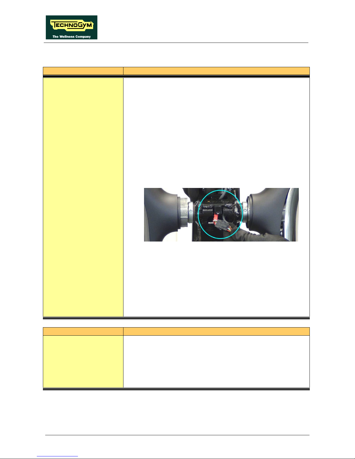
CROSS PERSONAL: Service & maintenance manual - rev. 1.1
Page 7.8
7.8. DISMANTLING THE TOTAL LEVERS
OPERATION
DESCRIPTION
Dismantling the Total
Levers
1. Remove the “Front guards”.
2.
Remove the screws anchoring the internal plastic lever guard
(platform lever connection area), using a 2.5 mm hex key.
3.
Separate the internal lever guard (assembly with Fast Milano
fastener).
4. Unscrew the nut anchoring the Total lever to the platform lever.
17 mm bush
NOTE:
during reassembly, tighten using a 44Nm/33lbf.ft
torque spanner
5. Remove the headphone jack socket on the central frame.
6. Slide out t he lever cable connector from the slot in the frame of
the central headphone jack socket housing (see photo below).
7. Loosen the 2 grub screws anchoring t he Total lever to the frame
pin, using a 3 mm hex key.
NOTE:
during reassembly, place a couple of drops of
Loctite threadlocker on the grub screws.
8. Slide the lever off sideways.
NOTE:
Take care not to pinch the cable when
reassembling.
OPERATION
DESCRIPTION
Dismantling the upper
part of the Total Lever
1.
Open the Total Lever internal guard, referring to the related
dismantling procedure.
2. Unscrew the 4 screws anchoring th
e upper part, using a 5 mm
hex key.
3. Remove the upper lever.

CROSS PERSONAL: Service & maintenance manual - rev. 1.1
Page 7.9
7.9. DISMANTLING THE TWEETER FROM THE TOTAL
LEVER
OPERATION
DESCRIPTION
Dismantling the tweeter
from the Total Lever
1.
Remove the top end cap from the Total lever and the tweeter
cover. Unscrew the screws, using a 2.5 mm hex key.
2.
Unscrew the 2 screws anchoring the tweeter support, using a
Phillips screwdriver.
3. Remove the tweeter.

CROSS PERSONAL: Service & maintenance manual - rev. 1.1
Page 7.10
7.10. DISMANTLING THE PLATFORM LEVER
OPERATION
DESCRIPTION
Dismantling the Platform
Lever
1. Unscrew the screws in the lower-
rear platform lever area (see
photo below), using a 4 mm hex key.
2. Remove the end part of the chrome-plated lever guard.
3.
Unscrew the screw anchoring the platform lever to the crank,
using a 5 mm hex key.
NOTE: during reassembly, tighten using a 23Nm/17lbf.ft
torque spanner
4. Disconnect the lever from the crank.
5.
Disconnect the platform lever from the Total lever. (see
procedure for dismantling the “Total Lever”).
6. Remove the lower leve r guar d. 11 scre ws in the l ower par t of the
lever, using a Phillips screwdriver.
7. Remove the upper platform lever guard. 5 screws with washers
in the lower part of the lever, using a Phillips screwdriver.
Removing the hub.
8. Unscrew the hub assembly anchor nut, using a 13 mm spanner.
9. Unscrew the hub assembly anchor screws, usin
g a 5 mm hex
key.
10. Screw in an M10 bol t on the screw side and us e it to ta ke out the
hub anchor pin.

CROSS PERSONAL: Service & maintenance manual - rev. 1.1
Page 7.11
7.11. DISMANTLING THE MECHANICS/CRANK ASSEMBLY
OPERATION
DESCRIPTION
Dismantling the
Mechanics/Crank
assembly
1. Disconnect the platform lever from the crank (see “Platform
Lever” dismantling procedure.
2. Remove the crank guard cover.
3. Unscrew the 2 screws anchoring the round "mirror-finish" guard
to the frame, using a 4 mm hex key.
4. Unscrew the crank anchor screws, using a 5 mm hex key.
5. If necessary, use an extractor to remove the crank.
6.
Unscrew the 5 screws on the coupling, using a 5 mm hex key.
Use 3 of the 5 screws as an extractor, by screwing them into the
empty holes of the coupling.
NOTE:
tighten the screws to 16 Nm/12 lbf.ft. torque
Tighten the screws using a “star” sequence several
times to gradually achieve the right torque for all
the screws (see “star” sequence below).
7.
Disconnect the timing lever from the frame, using a 5 mm hex
key and a 13 mm spanner.
8. Remove the whole Lever Assembly.
NOTE: during reassembly, perform the “Mechanics/Crank
assembling timing procedure”.

CROSS PERSONAL: Service & maintenance manual - rev. 1.1
Page 7.12
7.12. DISMANTLING THE CRANK ASSEMBLY BELT
OPERATION
DESCRIPTION
Dismantling the Crank
assembly belt
1. Dismantle the “Mechanics/crank assembly”.
2. Slacken the belt tension by turning the belt
stretcher eccentric
anchor screw, using a 5 mm hex key.
3. Remove the belt.
NOTE: during reassembly, perform the “Mechanics/Crank
assembling shaping procedure”.

CROSS PERSONAL: Service & maintenance manual - rev. 1.1
Page 7.13
7.13. DISASSEMBLY OF THE REAR GUARDS
OPERATION
DESCRIPTION
Disassembly of the rear
guards
1. Disconnect the platform lever from the crank (see “Platform
Lever” dismantling procedure.
2. Remove the crank guard cover.
3. Unscrew the 2 screws anchoring the round "mirror-finish" guard
to the frame, using a 4 mm hex key.
4. Remove the lower central tunnel (assembly wi
th Fast Milano
fastener).
5.
Remove the central (front) guard covering the mechanics. 1
screw, using a 4 mm hex key + Fast Milano fastener.
6.
Remove the central (rear) guard covering the mechanics
(assembly with Fast Milano fastener).
On the right-hand side of the equipment.
7.
Unscrew the screw anchoring the side guard covering the
mechanics to the central tunnel frame, using a 4 mm hex key.
8.
Unscrew the 11 screws anchoring the side guard covering the
assembly to the frame, using a 4 mm hex key and remove it.
On the left-hand side of the equipment.
9.
Unscrew the screw anchoring the side guard covering the
mechanics to the central tunnel frame, using a 4 mm hex key.
10.
Unscrew the 10 screws anchoring the side guard covering the
assembly to the frame, using a 4 mm hex key and remove it.

CROSS PERSONAL: Service & maintenance manual - rev. 1.1
Page 7.14
7.14. DISMANTLING THE BRAKE BELT
OPERATION
DESCRIPTION
Dismantling the Brake
Belt
On the right-hand side of the equipment
1. Disconnect the platform lever from the crank (see “Platform
Lever” dismantling procedure).
2. Remove the crank guard cover.
3. Unscrew the 2 screws anchoring the round "mirror-finish" guard
to the frame, using a 4 mm hex key.
4.
Using a tape measure, take the reference measurement for the
position of the screw of the belt tensioner, and then use it to
readjust the belt tension during reassembly.
5. Slacken the belt tension.
NOTE:
during reassembly, perform the “Belt tension
adjustment” procedure.
6. Mark the position of the timing lever on the frame.
7. Unscrew the screw anchoring the shaping lever, using a 5 mm
hex key and a 13 mm spanner.
NOTE: during reassembly, perform the “Mechanics/Crank
assembling shaping procedure”.

CROSS PERSONAL: Service & maintenance manual - rev. 1.1
Page 7.15
7.15. DISMANTLING THE BRAKE BELT PULLEY
OPERATION
DESCRIPTION
Dismantling the Brake
Belt Pulley
1. Remove the right-hand “Mechanics/crank assembly”.
2. Remove spline from the shaft.
3. Remove the spacer.
4. Remove the pulley. 4 screws, using a 13 mm spanner

CROSS PERSONAL: Service & maintenance manual - rev. 1.1
Page 7.16
7.16. DISMANTLING THE LOW KIT, POWER CARD, BRAKE
AND FLYWHEEL
OPERATION
DESCRIPTION
Dismantling the Low Kit,
Power Card, Brake and
Flywheel
On the left-hand side of the equipment
1. Disconnect the platform lever from the crank (see “Platform
Lever” dismantling procedure).
2. Remove the crank guard cover.
3. Unscrew the 2 screws anchoring the round "mirror-finish" guard
to the frame, using a 4 mm hex key.
4. Remove the side guard coverin
g the mechanics assembly (see
“Rear guard” dismantling procedure).
5. It is now possible to re move the Low Kit, the Power Card and
the Brake.
Removing the flywheel.
6. Unscrew the M20 ring anchoring t he flywheel to the secondary
shaft.
7. Remove the flywheel.

CROSS PERSONAL: Service & maintenance manual - rev. 1.1
Page 8.1
8. ADJUSTMENTS
8.1. MECHANICS/CRANK ASSEMBLY SHAPING
OPERATION
DESCRIPTION
Mechanics/Crank
assembly Shaping
NOTE_1:
The procedure described below differs according to
whether it is performed on the right-hand or the lefthand assembly.
Note that the references for the right-hand “R” and left-
hand “L” configuration are stamped on the aluminium
block (in the red circle in the illustration above).
NOTE_2:
Before performing the following procedure, check
that the crank is fitted.
NOTE_3: If the timing belt of
the mechanics/crank assembly
has not been removed, timing only requires
repositioning of the timing lever in the previous
position (previously marked on the frame) otherwise
follow the instructions below.
1. Remove the belt from the positive drive pulley.
Continued on the next page…

CROSS PERSONAL: Service & maintenance manual - rev. 1.1
Page 8.2
OPERATION
DESCRIPTION
Mechanics/Crank
assembly Timing
2. Position the crank midway between the two holes on the support
plate and block it in place by inserting two keys into the holes
(see detail circled in blue in the illustration below).
3. Position the timing lever at the centre of the “R” or “L” reference,
on the aluminium block, depending on the side on which the
mechanics/crank assembly is to be installed (the installation
shows timing for the left-hand side).
4. After correctly positioning the crank and the timing lever, insert
the belt onto the pulleys, maintaining the timing.
5. Refit the assembly on the equipment and tighten the shrink disk.
Continued on the next page…
 Loading...