


SERVICE & MAINTENANCE MANUAL
REV. 1.0


The information contained in this manual is intended for QUALIFIED TECHNICIANS who have
completed a specific TECHNOGYM training course and are authorized to perform machine start-
up and adjustment procedures as well as extraordinary maintenance or repairs which require a
thorough knowledge of the machine, its operation, its safety devices and working procedures.
CAREFULLY READ THE INFORMATION CONTAINED IN
THIS MANUAL BEFORE PERFORMING ANY MAINTENANCE
PROCEDURES ON THE MACHINE
DANGEROUS VOLTAGES
PRESENT
NOTE
The information contained in this document is subject to change without notice.
Technogym does not guarantee this documentation in any way. Technogym shall not be held
responsible for any errors contained in this manual and declines all liability for accidents or
damages resulting from the supply, characteristics or use of this manual.
This document contains proprietary information that is protected by copyright. All rights reserved.
No part of this document may be photocopied, reproduced or translated into another language
without the prior written consent of Technogym.
The Technogym™ trademark is property of Technogym S.p.A.
The Bike MED™ trademark is property of Technogym S.p.A.


BIKE MED: Service & Maintenance Manual - rev. 1.0
Contents
1. GENERAL NOTICES ........................................................................................................................................... 1.1
1.1. INTRODUCTION.................................................................................................................................................1.1
1.2. RECOMMENDATIONS........................................................................................................................................1.1
1.3. GENERAL RULES FOR REPAIR PROCEDURES ...................................................................................................... 1.2
2. TECHNICAL CHARACTERISTICS..................................................................................................................2.1
2.1. PRODUCT CODES...............................................................................................................................................2.1
2.2. MECHANICAL CHARACTERISTICS ..................................................................................................................... 2.2
2.3. FUNCTIONS AND CHARACTERISTICS TABLE ...................................................................................................... 2.3
2.4. AMBIENT SPECIFICATIONS................................................................................................................................2.3
2.5. CONFORMITY TO REGULATIONS........................................................................................................................2.4
2.6. WIRING DIAGRAM ............................................................................................................................................ 2.5
2.7. CABLES............................................................................................................................................................2.6
3. PRINCIPLES OF OPERATION..........................................................................................................................3.1
3.1. BLOCK DIAGRAM..............................................................................................................................................3.1
3.1.1. ARM display board ..............................................................................................................................3.1
3.1.2. CSafe Board .........................................................................................................................................3.2
3.1.3. TGS reader...........................................................................................................................................3.2
3.1.4. Hand sensor board...............................................................................................................................3.2
3.1.5. Cardio receiver .................................................................................................................................... 3.2
3.1.6. Brake board..........................................................................................................................................3.2
3.1.7. Brake 3.3
3.1.8. Speed sensor.........................................................................................................................................3.3
3.1.9. Power entry module ............................................................................................................................. 3.3
3.2. BRAKE CONTROL..............................................................................................................................................3.4
3.2.1. Mechanics ............................................................................................................................................ 3.4
3.2.2. Control 3.4
3.2.3. The signals involved.............................................................................................................................3.6
4. ACCESSORIES ..................................................................................................................................................... 4.1
4.1. CARDIO THEATER CONNECTION........................................................................................................................4.1
4.2. PC LINK FOR PROGRAMMING............................................................................................................................ 4.1
4.3. MONITOR PLUG FOR CSAFE PORT.....................................................................................................................4.2
5. INSTALLATION INSTRUCTIONS....................................................................................................................5.1
5.1. SPECIFICATIONS AND REQUIREMENTS .............................................................................................................. 5.1
5.2. INSTALLATION.................................................................................................................................................. 5.1
5.3. FIRST POWER-ON .............................................................................................................................................. 5.1
6. TROUBLESHOOTING ........................................................................................................................................ 6.1
6.1. SERVICE TROUBLESHOOTING MENU.................................................................................................................. 6.2
6.1.1. Automatic Test......................................................................................................................................6.2
6.1.1.1. I2C Devices Test.............................................................................................................................................................6.3
6.1.1.2. LED Test (not on 700iE models)....................................................................................................................................6.3
6.1.1.3. Serial Ports Test..............................................................................................................................................................6.3
6.1.2. Manual Test..........................................................................................................................................6.3
6.1.2.1. Man. Keyboard Test........................................................................................................................................................6.4
6.2. THE DISPLAY FAILS TO ILLUMINATE .................................................................................................................6.5
6.3. “THE EQUIPMENT IS BLOCKED” MESSAGE ON THE DISPLAY ................................................................... 6.7
6.4. ERROR DETECTED BY BRAKE BOARD ................................................................................................................ 6.8
6.4.1. Error 1 on brake board........................................................................................................................ 6.8
6.4.2. Error 2 on brake board........................................................................................................................ 6.8
Page i

BIKE MED: Service & Maintenance Manual - rev. 1.0
Page ii
6.4.3. Error 4 on brake board........................................................................................................................ 6.8
6.4.4. Error 8 on the brake board ..................................................................................................................6.9
6.4.5. Error 16 or 32 on the brake board ....................................................................................................... 6.9
6.4.6. Error 128 on brake board.................................................................................................................... 6.9
6.5. THERE IS NO RESISTANCE ...............................................................................................................................6.10
6.6. THE RESISTANCE IS INCORRECT ......................................................................................................................6.11
6.7. THE SPEED SIGNAL IS INCORRECT ................................................................................................................... 6.13
6.8. THE MACHINE DOES NOT READ THE TGS .........................................................................................................6.15
6.9. THERE IS NO HEART RATE SIGNAL...................................................................................................................6.17
6.9.1. HFU telemetric receiver.....................................................................................................................6.17
6.9.2. Hand sensor ....................................................................................................................................... 6.18
6.10. THE TELEMETRIC HR SIGNAL IS INCORRECT....................................................................................................6.20
7. DISASSEMBLY OF COMPONENTS.................................................................................................................7.1
7.1. DISASSEMBLING THE DISPLAY..........................................................................................................................7.1
7.2. DISASSEMBLING THE CIRCUIT BOARDS ON THE DISPLAY................................................................................... 7.2
7.3. DISASSEMBLING THE KEYBOARD......................................................................................................................7.3
7.4. DISASSEMBLING THE CARDIO RECEIVER...........................................................................................................7.4
7.5. DISASSEMBLING THE HANDLEBAR....................................................................................................................7.6
7.6. DISASSEMBLING THE SENSORS .........................................................................................................................7.7
7.7. DISASSEMBLING THE GUARDS ..........................................................................................................................7.8
7.8. DISASSEMBLING THE SEAT GROUP....................................................................................................................7.9
7.9. DISASSEMBLING THE ADJUSTING KNOB .......................................................................................................... 7.11
7.10. DISASSEMBLING THE ELECTRONIC BOX ..........................................................................................................7.12
7.11. DISASSEMBLING THE BELT .............................................................................................................................7.13
7.12. DISASSEMBLING THE PEDALS AND THE PEDAL CRANKS .................................................................................. 7.14
7.13. DISASSEMBLING THE PULLEY ......................................................................................................................... 7.15
7.14. DISASSEMBLING THE BRAKE WINDING............................................................................................................7.16
7.15. DISASSEMBLING THE BRAKE GROUP ...............................................................................................................7.17
7.16. DISASSEMBLING THE SPEED SENSOR............................................................................................................... 7.19
7.17. DISASSEMBLING THE PLATFORMS WITH CSAFE BOARD CONNECTORS AND POWER ENTRY MODULE ...............7.20
8. ADJUSTMENTS.................................................................................................................................................... 8.1
8.1. BELT TENSION .................................................................................................................................................. 8.1
8.2. PLAY OF SADDLE STEM.....................................................................................................................................8.2
8.3. SPEED SENSOR POSITION...................................................................................................................................8.3
8.4. BRAKE WINDING ASSEMBLY .............................................................................................................................8.4
9. MACHINE CONFIGURATION..........................................................................................................................9.1
9.1. USER MENU CONFIGURATION ...........................................................................................................................9.1
9.1.1. Language..............................................................................................................................................9.1
9.1.2. Distance................................................................................................................................................ 9.2
9.1.3. Priority setting...................................................................................................................................... 9.2
9.1.4. Maximum excercise time ......................................................................................................................9.2
9.1.5. Pause time ............................................................................................................................................ 9.3
9.1.6. Enable TGS ..........................................................................................................................................9.3
9.1.7. Enable keyboard................................................................................................................................... 9.3
9.1.8. Modifiable target heart rate.................................................................................................................9.3
9.1.9. Enable custom messages ...................................................................................................................... 9.4
9.1.10. Edit custom messages...........................................................................................................................9.4
9.1.11. Change messagges languages..............................................................................................................9.4
9.1.12. Enable multi-language mode............................................................................................................... 9.5
9.1.13. Resetting parameters to default values ................................................................................................ 9.5
9.1.14. SN 9.5
9.1.15. Communication protocols for external medical devices...................................................................... 9.5
9.2. SERVICE MENU CONFIGURATION ......................................................................................................................9.6
9.2.1. Low kit parameter ................................................................................................................................9.6
9.2.1.1. Read from low kit...........................................................................................................................................................9.7
9.2.1.2. Write to low kit...............................................................................................................................................................9.7

BIKE MED: Service & Maintenance Manual - rev. 1.0
9.2.1.3. Default Setting................................................................................................................................................................9.7
9.2.1.4. Configuration parameters table.......................................................................................................................................9.8
9.2.2. Operating data .....................................................................................................................................9.8
9.2.2.1. Read from low kit...........................................................................................................................................................9.9
9.2.2.2. Write to low kit...............................................................................................................................................................9.9
9.2.2.3. Machine usage data.........................................................................................................................................................9.9
9.2.3. Errors log............................................................................................................................................. 9.9
9.2.3.1. Read from low kit.........................................................................................................................................................9.10
9.2.3.2. Reset Errors...................................................................................................................................................................9.10
9.2.3.3. COM.Fault ....................................................................................................................................................................9.10
9.2.3.4. View Errors...................................................................................................................................................................9.11
9.2.4. Standard settings................................................................................................................................9.11
9.2.5. Low kit menu ......................................................................................................................................9.11
9.2.5.1. Low kit version.............................................................................................................................................................9.12
9.2.5.2. Low Kit fault code........................................................................................................................................................9.12
9.2.6. High kit version..................................................................................................................................9.12
9.2.7. BOOT version..................................................................................................................................... 9.12
10. SCHEDULED MAINTENANCE ....................................................................................................................... 10.1
10.1. DAILY MAINTENANCE OPERATIONS ................................................................................................................10.1
10.1.1. Setting up the operation.....................................................................................................................10.1
10.1.2. External cleaning operations ............................................................................................................. 10.1
10.2. MONTHLY MAINTENANCE OPERATIONS..........................................................................................................10.2
10.2.1. Play of the saddle stem.......................................................................................................................10.2
10.2.2. Check wear of foot straps...................................................................................................................10.2
10.2.3. Checking the operation of the cardiotester receiver..........................................................................10.2
10.2.4. Checking the operation of the hand sensor receiver.......................................................................... 10.2
10.3. TWICE-YEARLY MAINTENANCE OPERATIONS..................................................................................................10.3
10.3.1. Carrying out the monthly maintenance procedure.............................................................................10.3
10.3.2. Setting up the operation.....................................................................................................................10.3
10.3.3. Cleaning operations........................................................................................................................... 10.3
10.3.4. Checking the working conditions.......................................................................................................10.3
10.3.5. Checking the wear of rubber parts.....................................................................................................10.3
10.3.6. Checking the belt................................................................................................................................ 10.3
10.3.7. Checking the display..........................................................................................................................10.3
10.3.8. Checking the wiring and connections................................................................................................ 10.3
11. FUNCTIONAL TESTS .......................................................................................................................................11.1
11.1. ELECTRICAL SAFETY TEST..............................................................................................................................11.1
11.2. START-UP CHECK............................................................................................................................................11.2
11.3. CHECKING THE ASSEMBLY OF THE TRANSMISSION SYSTEM .....................................................11.3
11.4. CHECKING THE ASSEMBLY OF THE SEAT COMPONENTS..............................................................11.3
11.5. CHECKING THE ASSEMBLY OF THE GUARDS.......................................................................................11.3
12. APPENDIX...........................................................................................................................................................12.1
12.1. LIST OF CRITICAL SPARE PARTS ...................................................................................................................... 12.1
12.2. UPDATING THE SW ........................................................................................................................................ 12.1
12.3. REQUIRED TOOLS ...........................................................................................................................................12.2
Page iii

BIKE MED: Service & Maintenance Manual - rev. 1.0
Page iv
Page intentionally left blank

BIKE MED: Service & Maintenance Manual - rev. 1.0
1. GENERAL NOTICES
1.1. INTRODUCTION
This document is reserved for Technogym Service technicians, and is intended to provide
authorized personnel with the necessary information to correctly carry out repairs and maintenance.
A thorough knowledge of the technical information contained in this manual is essential for
completing the professional training of the operator.
In order to facilitate consultation, the paragraphs are accompanied by schematic drawings which
illustrate the procedure being described.
This manual contains notices and symbols which have a specific meanings:
WARNING: non observance may result in accident or injury.
ATTENTION: non observance may cause damage to the machine.
Information about the operation in progress.
OBSERVE: observation about the operation in progress.
1.2. RECOMMENDATIONS
Technogym recommends the following steps for planning repair procedures:
• Carefully evaluate the customer’s description of the machine malfunction and ask all the
necessary questions to clarify the symptoms of the problem.
• Clearly diagnose the causes of the problem. This manual provides the fundamental theoretical
basis, which must then be integrated by personal experience and attendance at the training
courses periodically offered by Technogym.
• Rationally plan the repair procedure so as to minimize the downtime necessary for procuring
spare parts, preparing tools, etc.
• Access the component to be repaired, avoiding any unnecessary operations. In this regard it will
be useful to refer to the disassembly sequence described in this manual.
Page 1.1

BIKE MED: Service & Maintenance Manual - rev. 1.0
Page 1.2
1.3. GENERAL RULES FOR REPAIR PROCEDURES
1. Always mark any parts or positions which may be confused with each other at the time of
reassembly.
2. Use original Technogym spare parts and lubricants of the recommended brands.
3. Use special tools where specified.
4. Consult the Technical Newsletters, which may contain more up-to-date information on
adjustments and maintenance than those contained in this manual.
5. Before starting the repair procedure, make sure that the recommended tools are available and in
good condition.
6. For the procedures described in this manual, use only the specified tools.
OBSERVE: The tool sizes quoted in this manual are expressed in mm.

BIKE MED: Service & Maintenance Manual - rev. 1.0
2. TECHNICAL CHARACTERISTICS
2.1. PRODUCT CODES
The machine codes take into account all the possible variants and options available for the products.
The machine code, which does not include the Serial Number, consists of 16 alphanumeric
characters arranged as follows:
Characters description key to values
1,2,3 Machine type: Bike
D82
4 Product version
7 = Bike MED
5 Type of power supply
M = multi-voltage EU
U = multi-voltage UL
6 Type of display
L = LED display
7
Device for downloading data used by the Wellness
System
N = not available
T = TGS
8, 9 Color of the frame
AL = aluminum
10, 11 Color of paddings
AG = gray
M0 = bordeaux
12 Guard color
G = gray
13 Type of TV model
0 = none
14,15 Language
IT = Italian
DE = German
FR = French
US = American English
NL = Dutch
BR = Portuguese
JP = Japanese
UK = British English
ES = Spanish
16 Type of packaging
I = Italy
E = standard international
S = overseas international
0 = none
The above coding is used for the entire Excite line. For this reason, options not relevant
to the Bike MED machine have also been included.
Page 2.1

BIKE MED: Service & Maintenance Manual - rev. 1.0
Page 2.2
For example, a possible product code would be:
D827MLTALM0G0UKE
which is interpreted as follows:
D82 7 M L T AL M0 G 0 UK E
standard international packing
British English language
no TV model
gray guards
burgundy paddings
aluminum frame color
interfaced to TGS key reader
LED display
mains powered supply with multi-voltage inlet EU
MED model
Bike
2.2. MECHANICAL CHARACTERISTICS
BIKE MED
Width
52 cm - 20.5 in
Length
120 cm - 47.3 in
Height
150 cm - 59.1 in
Weight
67 kg - 147 lbs

BIKE MED: Service & Maintenance Manual - rev. 1.0
2.3. FUNCTIONS AND CHARACTERISTICS TABLE
BIKE MED
Power supply
Multitension 90-260 Vac
Frequency
50 - 60 Hz
Resistance
10-1000 Watt
Consumption
100 W
Hand sensor
YES
Touch sensor
YES
CSafe
YES
HR receiver
HFU
Difficulty level
1-30
Program training
Quick start
Goal
6 profiles
Training Zone
CPR
Weight Loss
Custom program
Constant Power
Constant Torque
Sub Maximal Test
Fitness
Single stage
Multistage
PWC test
PWC test modified
YMCA test
Maximal Test
Technogym maximal test
Custom maximal test
Astrand
McArdle
Anaerobic power test
CHARACTERISTICS
Military Test
Air Force PRT
2.4. AMBIENT SPECIFICATIONS
Operating from 5° to 35° C
Temperature
Storage from -10° to 70° C
Operating from 30% to 80% non-
condensing
Humidity
Storage from 5% to 85% non-
condensing
Page 2.3

BIKE MED: Service & Maintenance Manual - rev. 1.0
Page 2.4
2.5. CONFORMITY TO REGULATIONS
The machine conforms to the following standards:
Europe USA
Safety
EN 957-1
EN 957-5 classe SA
EN 60601-1
EN 60601-1-2
UL 60601-1
In addition:
• Electrical isolation class: Class I;
• Marks and Certificates: CE – GM (TUV) and UL;
• Protection rating: IP20.

BIKE MED: Service & Maintenance Manual - rev. 1.0
2.6. WIRING DIAGRAM
DISPLAY
HAND
SENSOR
BOARD
ARM DI SPLAY BOARD
KEYBOARD
CSAFE
BOARD
HFU
RECEIVE R
C
N
7
C
N
8
C
N
1
TGS
BOARD
C
N
1
C
N
9
C
N
1
C
N
3
C
N
2
BRAKE
POWER
ENTRY
MODU L E
BRAKE
BOARD
C
N
4
C
N
3
C
N
1
C
N
2
SPEED
SENSOR
CU122
Patch
Conn. 2
C
N
4
J
3
J
2
-
J
4
L UPPER
SENSOR
R LOWER
SENSOR
L LOWER
SENSOR
R U PPER
SENSOR
CBQ-30
RIGHT
TOUCH
SENSOR
C
N
6
LEFT
TOUCH
SENSOR
C
N
5
Patch
Conn. 1
CU106
CU108
VAC
CB-4 CB-3
CB-51
CB-26
CBQ-25-1
CBQ-32
CBQ-13
C
N
FE
FE
Page 2.5

BIKE MED: Service & Maintenance Manual - rev. 1.0
Page 2.6
2.7. CABLES
CB-3: Cable connecting upper and lower assemblies
Brake board – Display board
Brake board
CN1
Signal Color Display Board
CN1
2 Digital Gnd White 2
3 Power Gnd Orange 3
4 - sensing +5 Vdc digital Red 4
6 +12 Vdc Black 6
7 +5 Vdc Green 7
8 +sensing +5 Vdc digital Blue 8
CB-4: Serial communication cable between upper and lower assemblies
Brake board – Display board
Brake board
CN4
Signal Color Display Board
CN9
1 Digital Gnd Orange-White 1
2 Digital Gnd Orange 2
3 NC Green-White 3
4 Download Blue 4
5 Reset Blue-White 5
6 NC Green 6
7 485 Tx/Rx + Brown-White 7
8 485 Tx/Rx - Brown 8
CB-26: Touch sensor cable
Display board – Touch sensor
Display board
CN5 / CN6
Signal Color Touch sensor
1 + 5Vdc White 1
2 Lever button Brown 3
4 Reference Green 4
CB-51: Brake supply cable
Brake board – Brake – Speed sensor
Brake board
CN2
Signal Color Brake Speed sensor
1 Brake supply + Brown 10
2 Brake supply - Pink 5
3 RPM Orange Faston connected
to brown cable
4 RPM reference Blue eyelet

BIKE MED: Service & Maintenance Manual - rev. 1.0
CBQ-13: CSafe board cable
Display Board – CSafe Board
Display Board
CN8
Signal Color CSafe Board
CN1
1 Digital #1 Flat cable 1
… … … …
14 Digital #14 Flat cable 14
CBQ-25-1: Hand sensor board cable
Display Board – Hand Sensor Board
Display Board
CN4
Signal Color Hand sensor
board
J3
1 +5 Vdc power supply Red 2
5 Pulse out Blue 3
6 Reference Black 1
CBQ-30: Sensor cable
Hand Sensor Board - Sensors
Hand sensor
board
Sensors
J2 - J4
Signal Color
RH 1 RH 2 LH 1 LH 2
1 Right sensor signal Red up up - 2 Sensor signal reference White down down - 3 Gnd Shield - - - 4 Left sensor signal Black - - up up
5 Sensor signal reference Green - - down down
6 Gnd Yellow/green - - - -
CBQ-32: TGS cable
Display Board – TGS Board
Display Board
CN7
Signal Color TGS Board
CN1
1 +12 Vdc power supply Yellow 1
3 Rx White 8
5 Tx Green 7
9 Gnd Brown 3
Page 2.7

BIKE MED: Service & Maintenance Manual - rev. 1.0
Page 2.8
CU106: HFU receiver cable
HFU receiver – Patch conn. 1
HFU receiver Signal Color Patch conn.1
1 +5 Vdc power supply Blue 1
2 Pulse (beat to beat) Red 2
4 Gnd Black 4
CU108: HFU receiver cable
Patch conn. 1 –Display board
Patch conn.1 Signal Color Display board
CN3
1 +5 Vdc power supply Blue 8
2 Pulse (beat to beat) Red 1
4 Gnd Black 7
CU122: High voltage cable
Power entry module – Brake board
Power entry
module
Signal Color Brake board
CN3
F Line Blue 1
N Neutral Brown 3
T Earth Yellow/Green 5

BIKE MED: Service & Maintenance Manual - rev. 1.0
3. PRINCIPLES OF OPERATION
3.1. BLOCK DIAGRAM
The machine block diagram is illustrated in the figure below:
POWER
ENTRY
MODULE
DISPLAY
DISPLAY BOARDS
CSAFE
BOARD
RIGHT
SENSORS
LEFT
SENSORS
HAND
SENSOR
BOARD
TGS BO ARD
BRAKE
BOARD
CARDIO
RECEIVER
VAC
SPEED
SENSOR
BRAKE
KEYBOARD
TOUCH
SENSOR DX
TOUCH
SENSOR SX
3.1.1. ARM DISPLAY BOARD
This is the heart of the display: this is the circuit board which comprises the CPU, an ARM
microprocessor, its logic circuits and a FLASH EPROM containing the operating program for
the machine moreover, acts as the interconnection hub for all the components of the display
and serves as the point of connection with the electrical box. In fact it receives and process
signals from:
- Keyboard;
- Cardio receiver;
- TGS board;
- CSafe Board;
>
distributes the voltages received from the Brake board to the display;
Page 3.1

BIKE MED: Service & Maintenance Manual - rev. 1.0
Page 3.2
> exchanges, via the RS-485 serial link to the Brake board, the commands for controlling the
brake;
> controls the LEDs and the 7-segment displays which provide feedback about the exercise
session.
The board includes the following indicator LEDs:
LED name Color Description
LED1 yellow
if ON the +5 Vdc power supply from the
Brake board correctly reaches the board.
LED2 green
if ON the +12 Vdc power supply from the
Brake board correctly reaches the board.
3.1.2. CSAFE BOARD
This board makes available a communication port, on 1 externally accessible connector, which can
be used for interfacing compatible CSafe devices such as the CardioTheater readers. This connector
is situated on the back of the display. Another free connector is available on the board.
These connectors can also be interfaced, using a special cable, to an external PC for programming
the FLASH EEPROM.
3.1.3. TGS READER
This board enables the machine to read and write on the user's TGS key for performing workouts
programmed with the Wellness System.
3.1.4. HAND SENSOR BOARD
This is the board which manages the hand sensors, interfacing them to the display board. It
processes the analogue signal received from the sensors and outputs one pulse for each heart beat
that is detected. The signal level is normally 5 Vdc; it goes to 0 Vdc when the user’s hands are
placed on the contacts, and a 5 Vdc pulse (having a width of approximately 30 msec) is output at
each detected heart beat.
3.1.5. CARDIO RECEIVER
This board manages the signal received from the telemetric transmitter used by the person
exercising. It receives the power supply signal from the display board and outputs a negative logic
pulse for every heart beat that is detected: the signal level is normally 5 Vdc, with a pulse at 0 Vdc
(having a width of approximately 30 msec) at each heart beat.
The receiver reception area is approximately a circle with a 1 m radius. If there is electromagnetic
noise (produced by high voltage lines, radio transmitters, monitors, motors etc.) within this area, the
receiver becomes saturated and no longer receives any signal.
3.1.6. BRAKE BOARD
There are 2 versions of the brake board, one which is used on the mains powered version and the
other on the self-powered version. In either case, the brake board consists of:

BIKE MED: Service & Maintenance Manual - rev. 1.0
• Power supply section which generates the low voltages used by the machine: +5 Vdc and +12
Vdc. Depending on the machine version, these voltages will be generated either from the 110
VAC or 220 VAC mains supply, or from the alternator-battery.
• Section for RS-485 serial communications with the display board for:
- commands determining the resistance that is required of the brake;
- brake error messages;
- the commands for modifying the circuit board configuration parameters;
- the commands for viewing the errors logged by the circuit board.
• Section which generates the current for the brake winding: varying the current produces a
proportional variation in the resistance of the brake. The excitation current supplied to the brake
is a function of the effort level selected on the display and the RPM value measured by the
speed sensor (angular velocity of the brake disk and is determined by the values stored in the
braking table.
The board includes the following indicator LEDs:
LED name Color Description
LED1 green
if ON the board is supplying the brake winding.
if BLINKING the brake board is in an error condition.
LED2 yellow
if ON there is the +5 Vdc power supply from the
circuit board.
3.1.7. BRAKE
This is an eddy current brake, consisting of a flywheel mass and a flat copper disk that rotates in the
air gap of a winding. Variations in the winding current produce a change in the resulting field,
which consequently varies the eddy currents induced within the copper disk and hence its resistance
to movement.
The winding has a resistance of approximately 4.8 Ohm.
3.1.8. SPEED SENSOR
This consists of a magnetic induction sensor which detects the heads of the brake disk fixing
screws.
3.1.9. POWER ENTRY MODULE
This is a block consisting of:
• power inlet socket;
• power outlet socket;
• fuse-holder for protecting line voltage and neutral with two 3.15A fast-blow fuses.
Situated on the side of the rear platform, the power entry module has a maximum current rating of
10A.
Page 3.3

BIKE MED: Service & Maintenance Manual - rev. 1.0
Page 3.4
3.2. BRAKE CONTROL
3.2.1. MECHANICS
The movement of the pedals puts the brake into rotation by means of a belt. The speed sensor (only
on mains operated models) attached to the frame detects the heads of the screws which secure the
disk to the flywheel, and generates a signal proportional to the speed. On self powered machine, the
speed value is detected measuring a phase of the alternator.
3.2.2. CONTROL
The control block diagram is as follows:
CN9
RS-485
CN4
Brake board
1-2/CN2
Brake
Excitation Current
3-4/CN2
Pulses
Speed
sensor
Display Board
The resistance which the user perceives on the pedals is a combination of 2 factors:
• mechanical: mechanical efficiency of the linkages and more generally the mechanical friction
of the system as a whole. The mechanical friction has been measured in the laboratory and is
determined by a specific SW function of the upper kit.
• electrical: resistance produced by the brake;
To obtain a given exercise effort level, the display board sends the required value of “electrical”
resistance to the brake board via the RS-485 serial link. Based on the commands received and the
feedback signal from the speed sensor, the brake board will then apply the appropriate excitation
current to the brake winding and generate an electromagnetic field.
The value of the current applied is based on the value of the brake table memorized into
the brake board.

BIKE MED: Service & Maintenance Manual - rev. 1.0
When the brake interface board receives the signal to generate resistance, the green
LED illuminates.
The electromagnetic field produced by the winding and the rotation of the disk will induce eddy
currents in the disk itself, giving rise to a force which tends to brake its motion. This produces the
exercise resistance.
A higher brake excitation signal will produce a correspondingly higher exercise resistance. In
addition, for a given value of brake excitation, a higher speed of disk rotation will produce a
correspondingly higher exercise resistance.
Due to the eddy currents, energy is dissipated on the brake disk in the form of heat.
The brake board effects an open loop control of the brake, with no provision for
regulating the value of resistance produced. The precision of the braking system has a
tolerance of ±10%.
During the movement, the speed sensor detects the heads of the brake disk fixing screws, and
produces a speed feedback signal that is sent to the Brake board, on the mains operated machines.
On the self powered machines, the speed signal comes directly from the measure of an alternator
phase.
If the brake board does not receive a speed signal which indicates that an exercise
session is in progress, the machine will not produce any resistance.
During the movement, the brake board checks for possible malfunctions. The errors which can
occur are:
Error
Code
Description
1
OVERHEATING: this condition occurs when the temperature measured
by the sensor on the circuit board exceeds 90°C.
2
OVERCURRENT: this condition occurs when the current going to the
solenoid measured by the board exceed the max value.
4
UNDERVOLTAGE: this condition occurs when the +12 Vdc voltage
drops below 9.7 Vdc.
8
OVERVOLTAGE: this condition occurs when the +12 Vdc voltage goes
above 13.7 Vdc.
16
WATCHDOG: this condition occurs when the brake board SW crashes.
32
EPROM: SW error on the brake board.
128
MACHINE NOT CALIBRATED: this error condition occurs when the
calibration parameter stored in the brake board is incorrect.
In the case of error 128, the machine will continue to function completely, but the braking
resistance produced will not correspond to the value entered on the display. In all other cases, the
Page 3.5

BIKE MED: Service & Maintenance Manual - rev. 1.0
Page 3.6
brake board interrupts the supply of current to the brake and sends an error message to the display
board which displays the “THE EQUIPMENT IS BLOCKED” message.
3.2.3. THE SIGNALS INVOLVED
The machine uses the following control signals:
• RS-485 Signal
This is a digital signal exchanged between the brake board and the display board. There is no
provision for monitoring its state.
• Excitation current
This is the current generated by the brake board (pins 1-2 of connector CN2) which supplies the
brake winding. The current supplied is a function of the selected effort level and the speed of
the exercise.
• Pulses
This is the signal produced by the speed sensor, and has the waveform shown below:
Figure 3.2-1
The signal enters the brake board (pins 3-4 on connector CN2), where it is used to determine the
speed value that is sent to the display board via the RS-485 serial link.
This signal can also be measured qualitatively using a multimeter. With the machine
stopped the voltage measured across the sensor terminals should be 0 Vdc, and while
pedaling it should go to a few hundred mV: the higher the speed, the higher the
measured value.

BIKE MED: Service & Maintenance Manual - rev. 1.0
4. ACCESSORIES
4.1. CARDIO THEATER CONNECTION
The machine can be connected to the CardioTheater by means of the RJ45 connector on the CSafe
board. The CardioTheater unit must be provided with a power cable having the following pin-out:
RJ45 Connector Signal
5 +5 Vdc
7 Ground
ATTENTION: for the numbering of the pins, on RJ45 connector, please refer to the
diagram below:
4.2. PC LINK FOR PROGRAMMING
The machine can be connected to a PC for programming by means of the RJ45 connector on the
CSafe board.
The cable to use (code 0WC00434AB) must be wired as follows:
ATTENTION: for the numbering of the pins, on RJ45 connector, please refer to the
diagram below:
Page 4.1

BIKE MED: Service & Maintenance Manual - rev. 1.0
Page 4.2
When programming the machine sometimes it is necessary to fit plug into the free RJ-45
port on the back of the display, to avoid any type of interference during the operation.
The wiring diagram of the RJ-45 plug is as follows:
Programming cable and plug can be ordered using the code H0002534AA.
4.3. MONITOR PLUG FOR CSAFE PORT
When the plug code 0WC00639AA is fitted into any one of the CSafe ports on the machine, the
corresponding LED should illuminate to indicate the presence of the 5 Vdc supply on the port.
During the CSafe port test function, the plug connects the transmit channel directly to the receive
channel, thereby producing a positive test outcome if the port is functioning correctly.

BIKE MED: Service & Maintenance Manual - rev. 1.0
5. INSTALLATION INSTRUCTIONS
5.1. SPECIFICATIONS AND REQUIREMENTS
For correct machine installation, make sure that:
1. The machine is installed on a level surface that is free of vibrations and has sufficient carrying
capacity for the combined weight of the machine and user.
2. The place of installation is free of dust and sand.
3. The place of installation meets the operating temperature and humidity conditions specified in
paragraph 2.4. “Ambient specifications”.
4. The machine is not positioned close to sources of heat, sources of electromagnetic noise
(television sets, electrical motors, antennas, high voltage lines, household appliances, etc...) or
medical equipment.
5. To eliminate any interference with the cardio receiver, no transmitters should be placed less
than 1 meter from the display.
6. The mains voltage must match the value specified on the machine rating plate.
7. The electrical system must be correctly earthed.
8. The wall outlet used should be reserved for the machine and have a rating of at least 50 VA.
9. Position the mains lead of the machine where it will not be underfoot.
5.2. INSTALLATION
To correctly install the machine, proceed as follows:
1. Ensure that the specifications and requirements for installation have been met (see paragraph
5.1. “Specifications and requirements”).
2. Position the machine as specified above, on a level surface that is free of vibrations and has
sufficient carrying capacity for the combined weight of the machine and user.
3. The machine is shipped fully assembled and packed in a carton fixed to a wooden pallet.
4. Connect the mains lead to the power inlet socket on the machine.
5. Place the on/off switch in the “0” position.
6. Plug the mains lead into the wall outlet.
5.3. FIRST POWER-ON
After completing the installation procedure, the machine is ready for use.
Simply turn the on/off switch from position 0 to position 1, to get on the machine.
On power-up the machine performs a self test of the upper and lower assemblies. At the end of this
the machine goes into standby, awaiting a keyboard command.
To check the correct operation of the machine:
Page 5.1

BIKE MED: Service & Maintenance Manual - rev. 1.0
Page 5.2
• get on the machine;
• begin exercising;
• check that the displayed speed varies accordingly;
• check that the exercise resistance varies when the “+” and “-” keys and the touch sensor are
pressed and the effort level change from 1 to 30;
• put on the heart rate meter and check that the machine correctly reads the heart rate value;
• grasp the sensors and check that the machine correctly reads the heart rate value;

BIKE MED: Service & Maintenance Manual - rev. 1.0
6. TROUBLESHOOTING
The troubleshooting procedures are shown in the form of flow charts. In order to facilitate
consultation, the following standard box shapes are used.
This type of box is the START point of the troubleshooting procedure. It
typically contains a description of the problem or malfunction.
This type of box represents a decision point in the troubleshooting procedure.
It typically contains a description of the CHECK to be made, with an outcome
that can be either a positive (YES) or negative (NO) response.
This type of box is a step in the troubleshooting procedure where an ACTION
must be carried out. It typically contains a description of the ACTION
necessary to resolve the problem. Therefore, after executing the specified
ACTION:
1. Check whether the problem has been resolved;
2. If the problem persists, it is recommended to resume the troubleshooting
procedure from the point before the action was carried out.
A circled number (such as that shown on the left) next to a box of the
troubleshooting procedure indicates that detailed instructions for performing
that particular check or action are provided below the flowchart.
A circled letter (such as that shown on the left) is used to highlight a point in
the procedure. Typically, this indicator is used in page changes.
Page 6.1

BIKE MED: Service & Maintenance Manual - rev. 1.0
Page 6.2
6.1. SERVICE TROUBLESHOOTING MENU
Simultaneously press the keys 369. The following prompt appears on the display:
ENTER PASSWORD:
To access the procedure, type in the password 2501 which protects against unauthorized access and
press the “Enter” key to confirm. At this point there are two options available:
1 = Tech Config
2 = Troubleshooting
Press numeric key 1 to access the menu for configuring technical parameters; the machine display
will begin showing the current configuration, structured as in the diagram below:
MAN.KEYBOARD
TEST
TROUBLESHOOTING
I2C Devices Test
AUTOMATIC TEST MANUAL TEST
LED Test
SERI AL PORT S
TEST
CSafe COM Test
TGS COM Test
Low Kit COM Test
To scroll through the list of available functions, press the + or – effort level keys to display the next
or the preceding item; confirm the choice by pressing ENTER. To cancel the operation, press the
CLEAR key for a few seconds.
The tests are divided into two groups: Automatic and Manual, and the prompt for a choice appears
immediately on accessing the troubleshooting menu.
6.1.1. AUTOMATIC TEST
The tests grouped under this section conduct checks on the machine’s operation in a fully automatic
manner. After selecting the desired test using the + and – effort level keys, press ENTER to initiate
the test and then await the result. Press ENTER again to continue, and use the CLEAR key to

BIKE MED: Service & Maintenance Manual - rev. 1.0
return to the higher menu level, holding it down for a few seconds. The various tests are described
below.
6.1.1.1. I2C Devices Test
The I2C Devices test checks the communication following the 32K and 256K. The test can have
outcomes:
• “Test Successful, press Enter to continue”: Signifies that the transmission and reception of
data packets between the I2C devices and the display board was completed successfully.
• “EEPROM Error, press Enter to continue”: Signifies that the display board is having
problems communicating with its memories.
6.1.1.2. LED Test (not on 700iE models)
The LED test checks the functioning of the display by lighting all the LEDs in the matrix. It also
tests the buzzer by changing the frequency to produce a variation in the tone of the sound.
There is no message displayed concerning the outcome of this test, which must therefore be
checked visually.
6.1.1.3. Serial Ports Test
The serial ports test checks the communications on the following interface ports:
• CSafe COM test;
• Low Kit COM test;
• TGS COM test.
Using the + and – effort level keys, select the desired test item and confirm by pressing ENTER.
The test can have two outcomes:
• “Test Successful, press Enter to continue”: This means that the test was completed
successfully, i.e. that the communications on the selected serial port are functioning correctly.
• “COMx error, press Enter to continue”: This means that the outcome of the test was
negative: the message will specify COM1 in the case of the CSafe COM test, COM2 in the case
of communications with the low kit, or COM3 in the case of the TGS COM test.
The “TGS COM test” done on machine not provided with the key reader gives a fail
outcome. The same if the “CSafe COM test” is done on a machine which CSafe port is
not plugged with the monitor plug described at paragraph 4.3. “Monitor plug for CSafe
port”.
6.1.2. MANUAL TEST
The tests grouped under this section conduct checks on the machine’s operation in a fully automatic
manner. After selecting the desired test using the + and – effort level keys, press ENTER to initiate
the test and then await the result. To exit test mode, press and hold down the CLEAR key for a few
seconds.
Page 6.3

BIKE MED: Service & Maintenance Manual - rev. 1.0
Page 6.4
6.1.2.1. Man. Keyboard Test
The manual keyboard test checks the functioning of all the keys on the keyboard. After accessing
the test by pressing ENTER, the message “Press all buttons (beep=OK)” appears on the display.
Pressing each key will produce an audible signal; if a key does not produce the beep it means it is
not working properly.
On Wellness TV machines, pressing the keys does not produce an audible signal, but if the key is
working correctly it lights up green.

BIKE MED: Service & Maintenance Manual - rev. 1.0
6.2. THE DISPLAY FAILS TO ILLUMINATE
This error occurs when the power supply voltage does not reach the upper assembly.
Does t he wall outlet s upply t he
correct voltag e?
Is t he m ains lead OK?
Is t h e v olt age at the
output of the machine's
power entry modul e
correct?
Plug the mac hi ne int o a
working elec trical out l et
Replac e the mains lead
Replac e the power
entry m odul e on the
machine
THE DISPLAY
DOES NO T
ILLUMINATE
NO
YES
NO
YES
NO
YES
A
1
Replace the f us es
YES
NO
Are the f uses OK?
Page 6.5

BIKE MED: Service & Maintenance Manual - rev. 1.0
Page 6.6
A
Are the DC v oltages at the
output of the brake board
correct?
3
YES
NO
Replac e the brake
board
Are the D C v oltages at t he
input t o t he dis play board
correct?
Replac e the display
board and/ or 3 86 board
Replace cable CB-3
NO
YES
4
Does t he m ai ns v oltage
reach t he input to the
brake boar d?
NO
2
Replace cable CB-0
YES
Follow the procedure step by step to correctly diagnose the problem. Take particular care with the
checks highlighted by circled numbers, which are described in detail below:
To speed up the troubleshooting procedure, check the state of the power indicator LEDs
on the various circuit boards.
(1) Slightly lift up the Faston connectors on the machine power inlet socket. Place the tester
probes across the live and neutral pins on the same connector. The measured value should be
approximately 220 VAC or 110 VAC depending on the mains voltage.
(2) As for step (1) but across pins 3 and 1 of connector CN3 on the brake board.
(3) Using a tester, check that all the output voltages on connector CN1 of the brake board are
correct, referring to paragraph 2.7. “Cables”.
(4) As for step (3) but on connector CN1 of the display board.
BIKE MED: Service & Maintenance Manual - rev. 1.0
6.3. “THE EQUIPMENT IS BLOCKED” MESSAGE ON THE
DISPLAY
This error message can be caused by:
• loss of communication between the lower and upper assemblies;
• the brake board has detected an error condition, causing it to generate an alarm and store the
error code in memory.
Is the serial
comm unic at ion bet ween
display and lower
elect ronic correct?
Reins tate t he
communication link
between the upper and
lower ass emblies
NO
"THE EQUIPMENT IS BLOCKED"
MESS A G E ON TH E DISPLAY
1
Carry out the "Error
detected by brak e
board" tr oubl es hooting
procedure
YES
2
3
Follow the procedure step by step to correctly diagnose the problem. Take particular care with the
checks highlighted by circled numbers, which are described in detail below:
(1) Use the serial communications test described in paragraph 6.1.1.3 “Serial Ports Test”.
(2) To reinstate communications between the lower and upper assemblies:
• check that cable CB-4 is correct using the Test Box Excite;
• try replacing the brake board and the display board in turn, and check whether the
communication works.
(3) Check whether the brake interface board is in an error condition, by accessing the “Low kit
fault code” function in the “Low kit menu” described in paragraph 9.2.5.2 “Low Kit fault
code”.
If the displayed parameter value is “0”, there is no error condition.
Page 6.7

BIKE MED: Service & Maintenance Manual - rev. 1.0
Page 6.8
6.4. ERROR DETECTED BY BRAKE BOARD
When the brake board detects an error, it stops and interrupts the power supply to the brake
winding, and an error code identifying the fault condition is saved in the error history log. When
this error is received by the display board, it halts the exercise and shows the “THE EQUIPMENT
IS BLOCKED” message on the display.
The errors logged by the brake board can also be viewed from the machine keyboard as described
in paragraph 9.2.3. “Errors log” or in paragraph 9.2.5.2 “Low Kit fault code”.
ERROR DETECTED BY
BRAKE BOARD
Check the error code
st or ed in m em or y
Error 1
Error 4
Error 8
Error 16 - 32
Error 2
Error 128
The following paragraphs describe the troubleshooting procedures for these cases.
6.4.1. ERROR 1 ON BRAKE BOARD
This code indicates an overheating error: this condition occurs when the temperature detected by
the sensor on the circuit board exceeds 90°C.
Try switching the machine off for 1 hour. If it resumes working correctly, the machine probably
overheated as a result of intensive use. If, on the other hand, the error persists, it is necessary to
replace the brake board.
6.4.2. ERROR 2 ON BRAKE BOARD
This code indicates an overcurrent error: this condition occurs when the current going to the
solenoid measured by the board exceed the max value.
This error is caused by an HW problem on the brake board or a short circuit on the solenoid. To
solve the problem, it is necessary to replace the brake board or the solenoid.
6.4.3. ERROR 4 ON BRAKE BOARD
This code indicates a low voltage error: this condition occurs when the +12 Vdc voltage drops
below 9.7 Vdc.

BIKE MED: Service & Maintenance Manual - rev. 1.0
This error is caused by drops in the voltage output by the power supply section of the brake board,
as a result of defective components. If the error persists or recurs frequently, replace the brake
board.
6.4.4. ERROR 8 ON THE BRAKE BOARD
This code indicates an overvoltage error: this condition occurs when the +12 Vdc voltage exceeds
13.7 Vdc.
This error is caused by surges in the voltage output by the power supply section of the brake board,
as a result of defective components. If the error persists or recurs frequently, replace the brake
board.
6.4.5. ERROR 16 OR 32 ON THE BRAKE BOARD
This code indicates an error in the EPROM of the brake board or a watch dog error: this condition
occurs when the board is unable to read the memory.
If the error persists or recurs frequently, replace the brake board.
6.4.6. ERROR 128 ON BRAKE BOARD
This code indicates an error in the calibration of the brake board: this condition occurs when the
value of the calibration parameter read by the board is incorrect. In these conditions, the board
continues to function but will not necessarily produce the correct value of exercise resistance.
When this error occurs, replace the brake board.
Page 6.9

BIKE MED: Service & Maintenance Manual - rev. 1.0
Page 6.10
6.5. THERE IS NO RESISTANCE
The machine will not produce resistance if:
• the display board does not receive a speed signal;
• the brake board does not generate current;
• the brake is defective.
Does the brake board supply
current to t he brake winding?
TH ER E IS N O
RESISTANCE
Are the Watt and RPM v al ues
shown on t he di s pl ay dif f erent
from zero?
NO
YES
1
Carry out the "RPM v alue
is incorrect "
troubles hoot ing proc edure
Replace the brake board
YES
Does t he br ak e winding receive
current f rom the brake board?
NO
Replace the brake winding
YES
Replac e cable CB-51
NO
2
Follow the procedure step by step to correctly diagnose the problem. Take particular care with the
checks highlighted by circled numbers, which are described in detail below:
(1) Disconnect the brake winding and measure the current output by the brake board with a load
of at least 5 Ohm and 80 Watts. The value should be different from 0 A.
(2) As for step (1) but with everything reconnected, and across the brake winding.

BIKE MED: Service & Maintenance Manual - rev. 1.0
6.6. THE RESISTANCE IS INCORRECT
The machine will produce an incorrect resistance if:
• the mechanics are not in perfect condition;
• the speed measurement is incorrect;
• the brake board is defective;
• the brake is defective.
Are the m echanics of t he
machine in good condition?
Has the brake board generated
error 128?
Does t he br ak e boar d out put
the correct current to the brake
winding?
3
Replace the brake board
NO
Replace the brake winding
YES
THE
RESIST ANCE IS
INCORRECT
1
Repair t he f ault y
mechanic al part s
NO
Carry out the "Speed is
Inc orrec t " t roubles hoot ing
procedure
2
Replace the brake board
YES
YES
NO
Follow the procedure step by step to correctly diagnose the problem. Take particular care with the
checks highlighted by circled numbers, which are described in detail below:
Page 6.11

BIKE MED: Service & Maintenance Manual - rev. 1.0
Page 6.12
(1) Check that the mechanical system, consisting of the pedals, belt and brake, moves smoothly
and without unusually high friction or resistance.
(2) Refer to paragraph 9.2.3. “Errors log”.
(3) Measure the voltage supplied by the brake board to the winding. In constant power mode
(custom – time), pedaling at 80 RPM and with a user weighing 75 kg, the values, according to
the firmware version of the brake board, should be approximately those in the tables below:
Low kit version 9.161.104
Power (Watt) Voltage (Vdc)
50 1.48
80 2.0
150 3.02
200 3.55

BIKE MED: Service & Maintenance Manual - rev. 1.0
6.7. THE SPEED SIGNAL IS INCORRECT
The speed signal is incorrect if:
• The brake disk is incorrectly fixed to the flywheel;
• The speed sensor is defective;
• The brake board is defective.
Does t he speed sens or s end
the c orr ec t signal to t h e brak e
board?
2
Replace the speed sensor
NO
SW not c orr ec t l y loaded
YES
Is t he brak e di s k correctly f ixed
to t he f l y wheel?
TH E SPEED IS
INCORRECT
1
Fix it correctly
NO
YES
Check if t he parameters
conf iguration is r ight. I s the
speed signal correct?
3
Configuration param et er
not c orrec t
YES
YES
Upload t he brak e board SW. Is
the s peed signal corre c t ?
4
Replace the brake board
NO
YES
Follow the procedure step by step to correctly diagnose the problem. Take particular care with the
checks highlighted by circled numbers, which are described in detail below:
Page 6.13

BIKE MED: Service & Maintenance Manual - rev. 1.0
Page 6.14
(1) Check that the 6 screws fixing the disk brake to the flywheel are all locked down.
The speed sensor detects the heads of these screws.
(2) Place the tester probes across the terminals of the speed sensor. The measured signal should
be that indicated in Figure 3.2-1. In addition, when pedaling at 80 RPM the frequency of the
signal should be 107 Hz.
The speed signal can also be observed qualitatively, using a multimeter. The value
should be 0 Vdc when the machine is stopped, and gradually increase as the speed
increases.
(3) Launch the default setting for the low kit parameters.
(4) Update the low kit SW uploading both firmware and brake table. At the end launch the
default setting for the low kit parameters.

BIKE MED: Service & Maintenance Manual - rev. 1.0
6.8. THE MACHINE DOES NOT READ THE TGS
The machine displays this error if the TGS reader is not working properly, or if it is not supplied by
the display board.
TH E MACHINE DO ES
NOT READ THE TGS
Does t he s upply voltage
correc t ly reach t he input t o t he
TGS reader?
Is t he s upply v olt age correct at
the output to the display board
correct?
Replac e cable CBQ-32
1
2
YES
NO
YES
Replace the display board
NO
A
Is t he serial comm unic at ion l ink
between the display board and
the TGS reader OK?
Replac e the TGS reader. Is the
comm unic at ion li nk bet ween the
displ ay board and t he TGS
reader OK?
TGS reader defect iv e
3
3
YES
NO
YES
Replace the display board
NO
A
Replace the TGS reader
Follow the procedure step by step to correctly diagnose the problem. Take particular care with the
checks highlighted by circled numbers, which are described in detail below:
Page 6.15

BIKE MED: Service & Maintenance Manual - rev. 1.0
Page 6.16
(1) Place the tester probes across pins 1 and 3 of connector CN1 of the TGS reader. The
measured value should be +12 Vdc.
(2) As for step (1) but across pins 1 and 9 of connector CN7 on the display board.
(3) Use the serial communications test described in paragraph 6.1.1.3 “Serial Ports Test”.

BIKE MED: Service & Maintenance Manual - rev. 1.0
6.9. THERE IS NO HEART RATE SIGNAL
6.9.1. HFU TELEMETRIC RECEIVER
The machine displays this error if:
1. electromagnetic noise saturate the HR receiver which does not display any value due to a
specific SW filter which cut every signal, greater than 220 bpm;
2. the receiver is not working properly;
3. the receiver is not supplied by the display board.
TH ER E IS N O HR
SIGNAL
Is t he supply v olt age c orrec t at
the input to t he rec e iv er?
Is t he supply v olt age c orrec t at
the output of t he di s pl ay board?
Replace the receiver
Replac e C BQ- 28 c abl e
2
3
YES
NO
YES
Replace display board
NO
Carry out the
troubl es hooting procedur e
"THE TELEMETRIC
SIGN AL I S INCOR R EC T"
1
Follow the procedure step by step to correctly diagnose the problem. Take particular care with the
checks highlighted by circled numbers, which are described in detail below:
(1) Carry out the troubleshooting procedure 6.10. “The telemetric hr signal is incorrect”.
(2) Place the tester probes across pins 1 and 3 of connector CN1 of the receiver. The measured
value should be +5 Vdc.
(3) As for step (1) but across pins 1 and 8 of connector CN3 on the display board.
Page 6.17

BIKE MED: Service & Maintenance Manual - rev. 1.0
Page 6.18
6.9.2. HAND SENSOR
The machine displays this error if the HS interface board is not working, or if it is not supplied by
the display board.
For an easier and quicker diagnosis of the problem, we recommend to use the
functions of Test Box Excite.
TH ER E IS N O HR
SIGNAL
Are the s ens ors c orrectly
connected to the HS interface
board?
Is t he supply v olt age c orrec t at
the output of t he di s pl ay board?
Reins tate t he c onnection
Replac e cable CBQ-25-1
Replace the display board
2
4
YES
NO
YES
NO
Is t he supply v olt age c orrec t at
the input to the HS interf ace
board?
Replace the HS interf ace
board
3
YES
NO
Check the earth c onnec t i on
of the mac hine
1
Follow the procedure step by step to correctly diagnose the problem. Take particular care with the
checks highlighted by circled numbers, which are described in detail below:
(1) Check the earthing of the machine using a tester to measure the resistance between the ground
pin on the power supply cable and the ground node to which the hand sensor are connected
inside the display. The value must be less than 1 Ohm.

BIKE MED: Service & Maintenance Manual - rev. 1.0
(2) Check the connections, referring to paragraph 2.6. “Wiring diagram”.
(3) Place the tester probes across pins 2 and 1 of connector J3 on the HS interface board. The
measured value should be +5 Vdc.
(4) As for step (2) but across pins 1 and 6 of connector CN4 on the display board.
Page 6.19

BIKE MED: Service & Maintenance Manual - rev. 1.0
Page 6.20
6.10. THE TELEMETRIC HR SIGNAL IS INCORRECT
The machine displays this error if the receiver is disturbed by sources of electromagnetic noise.
THE TELEMETRIC
HR SIGNAL IS
INCORRECT
Are the m achines c orrectly
spac ed by t he r equire d m inim u m
distance?
Is the receiver correctly
positioned and are the
connec ting cables properly
routed?
Are there s ourc es of
electromagnet ic noi s e near t he
receiv er?
Reposition the machines
so t hey are adequately
spaced
Correc t the pos ition of the
receiv er and the rout ing of
the c abl es
Move the machine away
from t he noi s e s ource or
att enuat e the power of the
noise
NO
YES
NO
YES
NO
YES
4
A
Check the earth c onnec t ion
of the mac hine
1
3
2
Continued on the following page.

BIKE MED: Service & Maintenance Manual - rev. 1.0
Is the transmitter always within
the 80 cm range f rom t he rec eiv er
NO
Reposition the transmitter
within range
YES
Replac e the receiv er
A
Is t h e t ransmitter in good
working order?
Us e a c orr ec t l y
funct ioni ng t r ans m itter
YES
NO
5
Follow the procedure step by step to correctly diagnose the problem. Take particular care with the
checks highlighted by circled numbers, which are described in detail below:
(1) Check the earthing of the machine using a tester to measure the resistance between the ground
pin on the power supply cable and the ground node to which the receiver is connected inside
the display. The value must be less than 1 Ohm.
(2) In the table below , the minimum distances at which machines should be installed to avoid
crosstalk problems.
B
I
K
E
B
I
K
E
2
BIKE
2
2
BIKE
2
DISTANCE CASING-CASING
machine 2 machine 2 machine 2 machine 2
Bike Recline Run Bike Recline Run Bike Recline Run Bike Recline Run
20 30 10 50 40 50 0 0 10 30 60 10
DISTANCE RECEIVER-RECEIVER
machine 2 machine 2 machine 2 machine 2
Bike Recline Run Bike Recline Run Bike Recline Run Bike Recline Run
130 140 195 100 90 115 80 50 130 170 230 225
Page 6.21

BIKE MED: Service & Maintenance Manual - rev. 1.0
Page 6.22
For machine positioning layouts different from those indicated above, use the following
diagram as a reference.
where:
1. The distances are in centimeters.
2. The smaller number indicates the maximum locking distance for signal reception at the
start of the exercise.
3. The higher number indicates the maximum reception distance during the exercise.
(3) Check that the cardio receiver has been assembled properly as described in the procedure 7.4.
“Disassembling the cardio receiver”.
(4) To check for electromagnetic noise near the machine, use Test Box Excite as detailed here
below. You can use one of the following cables ELT-16 (0WC00518AB), CBQ-28
(0WC00390AC) or TRM-28 (0WC00336AC) as connection cable.
The circuit lights the LED for each heart beat and/or disturbance received: in this way it is
possible to determine whether there is any interference, and identify its sources.
(5) Check the battery power level, using a tester if possible. Otherwise use a receiver or another
“reference” machine to check the operation up to a distance of about 80 cm from the receiver.
115
86
102
70
99
77
99
78
89
60
Receiver
103
82
103
83
95
76
TEST BOX
EXCITE
HR receive
r
HFU
Receiver
Connection
cable

BIKE MED: Service & Maintenance Manual - rev. 1.0
7. DISASSEMBLY OF COMPONENTS
7.1. DISASSEMBLING THE DISPLAY
Figure 7.1-1
1. Turn off the machine and unplug the mains
lead from the wall outlet.
2. Back off the 4 screws a using a medium
Phillips screwdriver.
Figure 7.1-2
3. Unplug the connectors indicated in the figure
at left.
4. Remove the display.
Figure 7.1-3
5. Unplug the connector indicated in the figure,
from the hand sensor board.
6. Back off the 2 screws b, using a 5-mm hex
wrench, to remove the rear display support.
To reassemble the display, carry out the above
steps in reverse order.
Page 7.1

BIKE MED: Service & Maintenance Manual - rev. 1.0
Page 7.2
7.2. DISASSEMBLING THE CIRCUIT BOARDS ON THE
DISPLAY
Figure 7.2-1
Carry out the procedure described in paragraph
7.1. “Disassembling the display”.
Then place the display on a work bench. It is
now possible to disassemble its circuit boards:
• The display board a;
• The CSafe board b.
Figure 7.2-2
Display board a:
1. Unplug the keyboard connector indicated in
the figure.
2. Back off the 4 screws c using a medium
Phillips screwdriver.
3. Remove the circuit board.
Figure 7.2-3
CSafe board b:
1. Unplug the connector indicated in the figure.
2. Remove the circuit board from the top.
To reassemble the electronics boards, carry out
the above steps in reverse order.

BIKE MED: Service & Maintenance Manual - rev. 1.0
7.3. DISASSEMBLING THE KEYBOARD
Figure 7.3-1
Carry out the procedure described in paragraph
7.1. “Disassembling the display”.
1. Unplug the keyboard connector shown in the
figure.
Figure 7.3-2
With the display placed on a work bench:
2. Use a sharp tool to lift up and detach a corner
of the keyboard.
To assemble a new keyboard, with the display on
a work bench:
1. Remove the backing film from the adhesive.
2. Apply the adhesive part, starting from the
left and working toward the right, without
bending the keyboard.
3. Insert the connector in the special slot on the
display and connect it to the display board.
4. Remove the protective film.
When reassembling the keyboard, make
sure that none of the keys are bent or
remain pushed in.
The keyboard assembly procedure can
only be carried out once, because
disassembly damages the tracks and
keys.
Page 7.3

BIKE MED: Service & Maintenance Manual - rev. 1.0
Page 7.4
7.4. DISASSEMBLING THE CARDIO RECEIVER
Figure 7.4-1
1. Back off the screw a using a small Phillips
screwdriver, reaching it through the hole 1.
2. To remove the cardio receiver casing:
• Pull it a little, out from the front side;
• Slide it downward to disengage the 2
screws you can see in the square of the
figure, from its slots on the frame;
• Pull the receiver casing out from the front
side.
Figure 7.4-2
3. Remove the receiver from its slot on the
machine.
4. Unplug the connector b.
Figure 7.4-3
To assemble the new receiver:
1. On the HFU receiver, there are the receiving
coil c and the connector d.
Continued on following page →

BIKE MED: Service & Maintenance Manual - rev. 1.0
Figure 7.4-4
5. Connect the cable to the cardio receiver and
bend the cable on a side of the connector.
Figure 7.4-5
6. Place the receiver in the sponge e as shown
in the picture to side.
The receiving coil must be oriented
upwards and toward the display.
7. Mount the cardio receiver casing again.
Page 7.5

BIKE MED: Service & Maintenance Manual - rev. 1.0
Page 7.6
7.5. DISASSEMBLING THE HANDLEBAR
Figure 7.5-1
Carry out the procedure described in paragraph
7.4. “Disassembling the cardio receiver”.
1. Remove the plastic covering a.
Figure 7.5-2
2. Back off the 3 screws a using a 6-mm Hex
wrench.
Support the handlebar before backing
off the last screw.
To assemble the new handlebar, carry out the
above steps in reverse order.
During reassembly, lock down the 3
screws using a torque wrench set for 22
Nm.

BIKE MED: Service & Maintenance Manual - rev. 1.0
7.6. DISASSEMBLING THE SENSORS
Figure 7.6-1
1. Turn off the machine and unplug the mains
lead from the wall outlet.
For each sensor:
2. Back off the 2 screws a using a small Phillips
screwdriver.
Figure 7.6-2
3. Lift up the top sensor.
4. Remove the lower sensor.
5. To disconnect the sensors, disconnect the
two faston shown in the figure.
6. To disconnect the touch sensors, disconnect
the connector b.
To reassemble the sensors, carry out the above
steps in reverse order.
Page 7.7
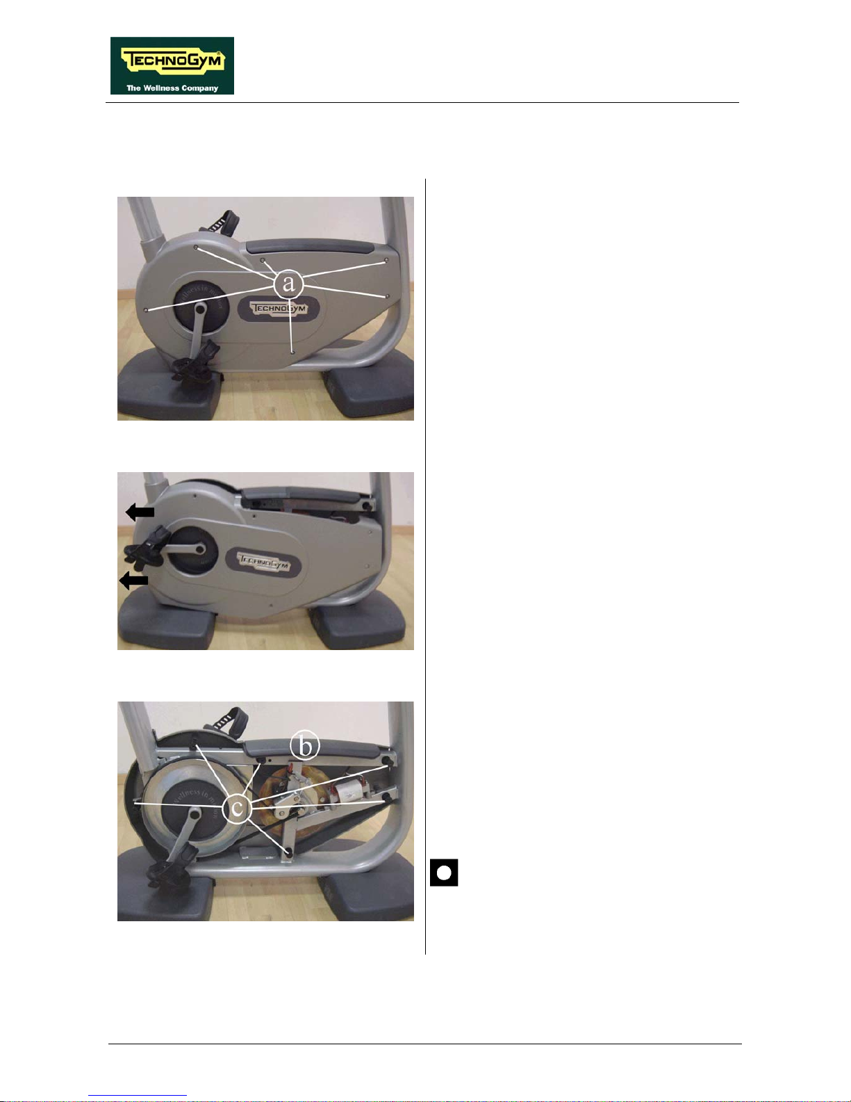
BIKE MED: Service & Maintenance Manual - rev. 1.0
Page 7.8
7.7. DISASSEMBLING THE GUARDS
Figure 7.7-1
1. Back off the 6 screws a on either side of the
machine using a 4-mm Hex wrench.
Figure 7.7-2
2. Remove the right guard first, pushing the
pedal back as shown in the figure, and then
removing the guard as indicated by the
arrows.
Figure 7.7-3
3. Remove the rubber footrest b.
4. Remove the six pins c from the left guard.
5. Push the left pedal back and remove the left
guard in the same way as the right guard.
To reassemble the guards, carry out the above
steps in reverse order.
During reassembly, lock down the
screws using a torque wrench set for 0.8
Nm.

BIKE MED: Service & Maintenance Manual - rev. 1.0
7.8. DISASSEMBLING THE SEAT GROUP
Figure 7.8-1
Carry out the procedure described in paragraph
7.7. “Disassembling the guards”.
1. Adjust the saddle to position 2.
2. Back off the screw a using a 3-mm Hex
wrench, accessing it from the hole at the base
of the saddle column.
3. Remove the saddle from the top.
Figure 7.8-2
Figure 7.8-3
Disassembling the adjustable bushing:
1. Back off the two screws b using a 3-mm Hex
wrench.
2. Remove the bushing from the top.
Continued on following page →
Page 7.9
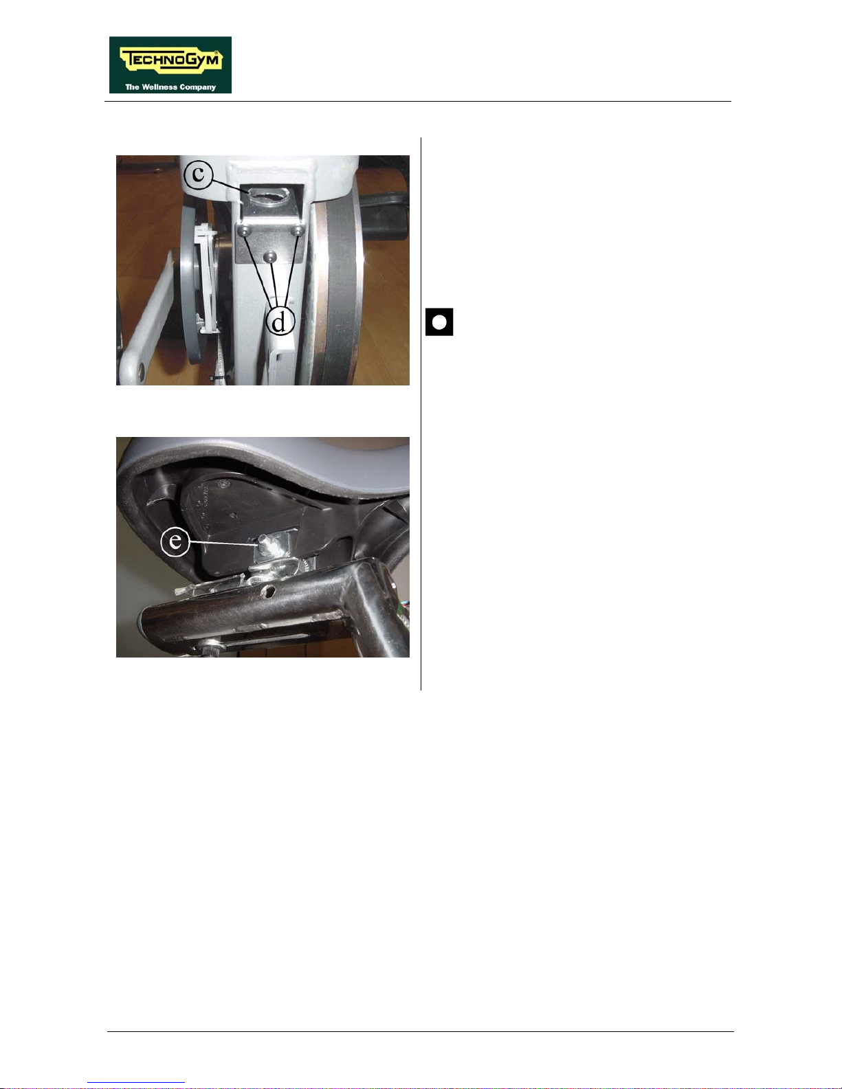
BIKE MED: Service & Maintenance Manual - rev. 1.0
Page 7.10
Figure 7.8-4
Disassemble the saddle stem bushing c:
1. Back off the three screws d using a 3-mm
Hex wrench.
2. Pull out the plate on which the bushing is
fixed.
During reassembly, lock down the
screws d using a torque wrench set for 5
Nm.
Figure 7.8-5
Disassemble the saddle:
1. Back off the nut e using a 13-mm wrench.
2. Remove the saddle.
To reassemble the saddle group, carry out the
above steps in reverse order.

BIKE MED: Service & Maintenance Manual - rev. 1.0
7.9. DISASSEMBLING THE ADJUSTING KNOB
Figure 7.9-1
Carry out the operations described in paragraph
7.8. “Disassembling the seat group”.
1. Remove the yellow cover a.
2. Use a 3-mm Hex wrench to back off the
screw underneath.
3. Remove the knob b, pulling from the
opposite side of the frame and being careful
to prevent the pin from dropping inside the
frame.
Figure 7.9-2
4. Remove the rubber o-ring c from the pin d
and pull the pin out from inside the frame.
5. Unscrew the threaded bushing e, using a 17mm wrench.
During reassembly, lock down the
threaded bushing “e” using a torque
wrench set for 40 Nm.
Figure 7.9-3
6. Remove the spring f from the frame.
To reassemble the guards, carry out the above
steps in reverse order.
Page 7.11

BIKE MED: Service & Maintenance Manual - rev. 1.0
Page 7.12
7.10. DISASSEMBLING THE ELECTRONIC BOX
Figure 7.10-1
Carry out the procedure described in paragraph
7.7. “Disassembling the guards”.
1. Back off the screw a using a medium Phillips
screwdriver.
2. Unplug the connectors indicated in the
figure.
3. Back off the two screws b using a 4-mm hex
wrench.
4. Remove the electronic box.
Figure 7.10-2
5. Back off the screws c using a medium
Phillips screwdriver.
6. Remove the cover of the box.
7. Remove the brake board.
To reassemble the electronic box, carry out the
above steps in reverse order.
During reassembly, lock down the
screws b using a torque wrench set for 5
Nm.

BIKE MED: Service & Maintenance Manual - rev. 1.0
7.11. DISASSEMBLING THE BELT
Figure 7.11-1
Carry out the procedure described in paragraph
7.7. “Disassembling the guards”
1. Release the spring a of the belt tensioning
mechanism.
2. Remove the belt from the pulley.
To reassemble the belt, follow the disassembly
instructions in reverse order.
After completing this operation, adjust
the belt tension as described in
paragraph 8.1. “Belt tension”.
Page 7.13

BIKE MED: Service & Maintenance Manual - rev. 1.0
Page 7.14
7.12. DISASSEMBLING THE PEDALS AND THE PEDAL
CRANKS
Figure 7.12-1
Carry out the procedure described in paragraph
7.7. “Disassembling the guards”.
1. Back off the screw a using a 15-mm wrench
and remove the pedal.
During reassembly, lock down the
screws “a” using a torque wrench set for
35 Nm.
Figure 7.12-2
2. Remove the plastic caps b from both pedal
cranks.
3. Use a 14-mm socket wrench to back off the
screw underneath.
Figure 7.12-3
4. Use a bicycle pedal extractor tool like the
one shown in the figure to remove the two
pedal cranks.
To reassemble the pedals and the pedal cranks,
carry out the above steps in reverse order.
During reassembly, lock down the
screws b using a torque wrench set for
40 Nm.

BIKE MED: Service & Maintenance Manual - rev. 1.0
7.13. DISASSEMBLING THE PULLEY
Figure 7.13-1
Carry out the operations described in paragraphs
7.11. “Disassembling the belt” and 7.12.
“Disassembling the pedals and the pedal cranks”.
1. On the left side of the machine, remove the
plastic cover a.
Figure 7.13-2
2. Remove the snap ring b.
Be careful with the various spacer rings
on the pulley shaft.
Figure 7.13-3
3. Remove the pulley c from the opposite side
of the machine.
4. Back off the 3 screws d using a medium
Phillips screwdriver.
5. Remove the plastic cover, not visible in the
photo, from the pulley c.
To reassemble the pulley, carry out the above
steps in reverse order.
Page 7.15

BIKE MED: Service & Maintenance Manual - rev. 1.0
Page 7.16
7.14. DISASSEMBLING THE BRAKE WINDING
Figure 7.14-1
Carry out the procedure described in paragraph
7.7. “Disassembling the guards”.
1. Back off the fixing screw a using a 4-mm
hex wrench and remove the right cover plate.
Figure 7.14-2
2. Back off the 2 fixing screws b using a 4-mm
hex wrench and remove the left cover plate.
3. Back off the two nuts c using a 7-mm
wrench, locking down the 2 through-screws
from the opposite side using a 3-mm Hex
wrench.
Figure 7.14-3
4. Unplug the two Faston connectors from the
winding.
5. Back off the 2 nuts c using a 13-mm wrench
locking down the bolts on the opposite side,
using a 5-mm wrench.
6. Remove the assembly with the winding.
To reassemble the brake winding, carry out the
above steps in reverse order.
Be careful to position the brake
assembly so that the copper disk does
not brush against the laminated core, as
described in paragraph 8.4. “Brake
winding assembly”.

BIKE MED: Service & Maintenance Manual - rev. 1.0
7.15. DISASSEMBLING THE BRAKE GROUP
Figure 7.15-1
Carry out the operations described in paragraphs
paragraph 7.7. “Disassembling the guards”, 7.11.
“Disassembling the belt” and 7.14.
“Disassembling the brake winding”.
1. Remove the snap ring a on the left side of the
machine.
Be careful with the various spacer rings
on the pulley shaft.
Figure 7.15-2
2. Remove the brake assembly
3. Place the brake assembly on a work bench.
Take particular care with the copper
disk, as it bends easily and may then
cause problems after reassembly, by
brushing against the winding block.
4. Back off the screws b using a 4-mm Hex
wrench.
5. Remove the copper disk.
Continued on following page →
Page 7.17

BIKE MED: Service & Maintenance Manual - rev. 1.0
Page 7.18
Figure 7.15-3
Disassembling the brake pulley c:
6. Unscrew the brake pulley c using a 17-mm
wrench, using a 6-mm Hex wrench to hold
the shaft in place on the opposite side.
To reassemble the brake, carry out the above
steps in reverse order.
Remember to fully lock down all the
screws “b” (in a cross pattern), as they
may knock against the speed sensor if
left loose. Lock down the screws using a
torque wrench set for 6 Nm.
After reassembling the brake, use a
comparator to check for any curvature
of the copper disk, with a margin of ±
0.15 mm.
Lock down the screw “c” using a torque
wrench set for 40 Nm.

BIKE MED: Service & Maintenance Manual - rev. 1.0
7.16. DISASSEMBLING THE SPEED SENSOR
Figure 7.16-1
Carry out the procedure described in paragraph
7.7. “Disassembling the guards”.
1. Back off the 2 screws a using a small Phillips
screwdriver.
2. Remove the speed sensor.
3. If it proves difficult to back off the screws a
in their current position, back off the screws
b using a 3-mm Hex wrench and remove the
sensor together with the support.
If the plastic sensor support is also
removed, adjust the sensor position as
described in paragraph 8.3. “Speed
sensor position”.
To reassemble the speed sensor, carry out the
above steps in reverse order.
Page 7.19

BIKE MED: Service & Maintenance Manual - rev. 1.0
Page 7.20
7.17. DISASSEMBLING THE PLATFORMS WITH CSAFE
BOARD CONNECTORS AND POWER ENTRY MODULE
Figure 7.17-1
The front and rear platforms house the following
components:
• connector of the cable leading to the CSafe
board (front platform, on the right in the
figure);
• Power entry module.
1. To access the connectors, turn the machine
over on one side.
2. Back off the screws a of the platform which
houses the desired connector, using a
medium Phillips screwdriver.
Figure 7.17-2
At this point it is possible to:
3. Unplug connector b of the cable which goes
up to the CSafe board.
4. Back off the two screws c and remove the
Power entry module.
Continued on following page →

BIKE MED: Service & Maintenance Manual - rev. 1.0
Figure 7.17-3
Disassembling the platforms (this procedure
applies for both platforms):
5. To disassemble the platforms, back off the 3
screws d using a 17-mm wrench.
To reassemble the platforms and connectors,
carry out the above steps in reverse order.
During reassembly, lock down the
screws “d” using a torque wrench set for
44 Nm.
Page 7.21

BIKE MED: Service & Maintenance Manual - rev. 1.0
Page 7.22
Page intentionally left blank

BIKE MED: Service & Maintenance Manual - rev. 1.0
8. ADJUSTMENTS
8.1. BELT TENSION
Figure 8.1-1
Carry out the procedure described in paragraph
7.7. “Disassembling the guards”.
1. To adjust the tension of the belt, simply
select on of the various positions available
for the spring a.
The correct belt tension is between 80-
100 Hz on a powered machine and
between 140-180 Hz on a self powered
machine.
Page 8.1

BIKE MED: Service & Maintenance Manual - rev. 1.0
Page 8.2
8.2. PLAY OF SADDLE STEM
Figure 8.2-1
1. Raise the machine saddle to be able to access
the 2 screws a, on the bushing.
2. Turn the screws a to adjust the play of the
saddle stem, using a 3-mm Hex wrench.

BIKE MED: Service & Maintenance Manual - rev. 1.0
8.3. SPEED SENSOR POSITION
Figure 8.3-1
Carry out the procedure described in paragraph
7.7. “Disassembling the guards”.
1. Back off the 2 screws a and shift the speed
sensor support to the side, so that it is 0.7
mm from the screws on the copper disk.
2. Lock the screws back down.
Page 8.3

BIKE MED: Service & Maintenance Manual - rev. 1.0
Page 8.4
8.4. BRAKE WINDING ASSEMBLY
Figure 8.4-1
Carry out the procedure described in paragraph
7.7. “Disassembling the guards”.
1. Back off the 2 screws a and shift the brake
winding support to the side, so that it is 0.6
mm from the disk.
2. Lock the screws back down.
WARNING: check the flatness of the
copper disk using a comparator gauge:
the permissible margin is ± 0.15 mm.

BIKE MED: Service & Maintenance Manual - rev. 1.0
9. MACHINE CONFIGURATION
9.1. USER MENU CONFIGURATION
The machine configuration procedure is invoked, when the machine is in standby mode, by
simultaneously pressing the keys 369. The following prompt appears on the display:
ENTER PASSWORD:
To access the procedure, type in the password 2406 and press ENTER to confirm. At this point the
machine display begins showing the current configuration, structured as in the diagram below:
USER MENU
Language
MAX Time
Priority
Distance
Pause Time
TGS
Keys
HR
Change Mes s.Lang.
Edi t Mes sages
Custom Mess.
Languages
Default config.
SN
EXT.
9.1.1. LANGUAGE
After selecting a language from the list of those available, all messages subsequently displayed by
the machine will be in the chosen language. To change the selection, when the display shows the
current setting:
LANGUAGE : xxx
Press the +/- GOAL keys to select the desired language from the options available. Press ENTER
to confirm the choice, use the + or – effort level keys to move to the next or previous parameter.
Page 9.1
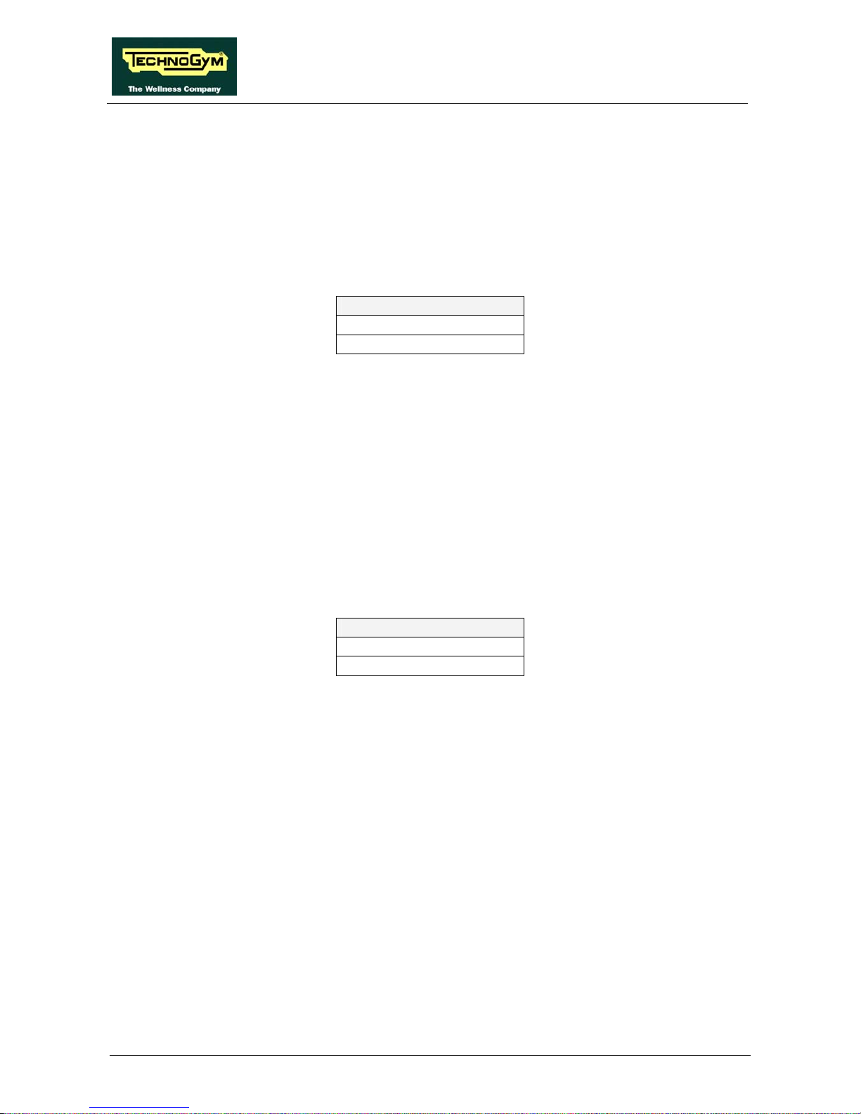
BIKE MED: Service & Maintenance Manual - rev. 1.0
Page 9.2
9.1.2. DISTANCE
It is possible to choose between EUROPEAN units (kg and km) or IMPERIAL units (pounds and
miles). To change the selection, when the display shows the current setting:
DISTANCE : xxx
Press the +/- GOAL keys to select the desired unit of measurement from the options listed in the
table below:
DISTANCE
KM <default>
MLS
Press ENTER to confirm the operation, use the + or – effort level keys to move to the next or
preceding parameter.
9.1.3. PRIORITY SETTING
If signals are available from both the chest band and hand sensors, this parameter determines which
is the preferential source for displaying the heart rate value. Obviously, if only one of these two
signals is available, it will be used even if not configured as the preferential heart rate source. To
change the selection, when the display shows the current setting:
PRIORITY : xxx
Press the +/- GOAL keys to select the preferential source from those listed in the table below:
PRIORITY
BAND <default>
HANDS
Press ENTER to confirm the operation, use the + or – effort level keys to move to the next or
preceding parameter.
9.1.4. MAXIMUM EXCERCISE TIME
It is possible to set a maximum duration for the exercise in minutes, with a value ranging from 1 to
9999. To change the setting, when the display shows the current maximum exercise time:
MAX TIME: xxx
Press the ENTER key to modify the value: when the current parameter value starts to blink, press
the CLEAR key to erase the current value and then use the number keys to enter the desired new
value.
Press ENTER to confirm the operation, use the + or – effort level keys to move to the next or
preceding parameter.
The default value of this parameter is 9999.

BIKE MED: Service & Maintenance Manual - rev. 1.0
9.1.5. PAUSE TIME
It is possible to set a maximum pause time for each exercise in seconds, with values ranging from
10 to 999. To change the setting, when the display shows the current maximum time:
PAUSE TIME : xxx
Press the ENTER key to modify the value: when the current parameter value starts to blink, press
the CLEAR key to erase the current value and then use the number keys to enter the desired new
value.
Press ENTER to confirm the operation, use the + or – effort level keys to move to the next or
preceding parameter.
The default value of this parameter is 60.
9.1.6. ENABLE TGS
It is possible to enable or disable the use of the TGS reader. To change the selection, when the
display shows the current setting:
TGS : xxx
Press the +/- GOAL keys to select the desired option out of those listed in the table below:
TGS
ENABLED <default>
DISABLED
Press ENTER to confirm the operation, use the + or – effort level keys to move to the next or
preceding parameter.
9.1.7. ENABLE KEYBOARD
It is possible to disable the keyboard so that the machine can only be used with the TGS. To change
the selection, when the display shows the current setting:
KEYS : xxx
Press the +/- GOAL keys to select the desired option out of those listed in the table below:
KEYS
ENABLED <default>
DISABLED
Press ENTER to confirm the operation, use the + or – effort level keys to move to the next or
preceding parameter.
9.1.8. MODIFIABLE TARGET HEART RATE
It is possible to enable or disable modification of the target heart rate during a constant heart rate
exercise. To change the selection, when the display shows the current setting:
Page 9.3

BIKE MED: Service & Maintenance Manual - rev. 1.0
Page 9.4
HR : xxx
Press the +/- GOAL number keys to select the desired option out of those listed in the table below:
HR
MODIFIABLE <default>
NOT MODIFIABLE
Press ENTER to confirm the operation, use the + or – effort level keys to move to the next or
preceding parameter.
9.1.9. ENABLE CUSTOM MESSAGES
It is possible to configure whether a custom message is displayed when the machine is in the
standby state. To change the selection, when the display shows the current setting:
CUSTOM MESS. : xxx
Press the +/- GOAL number keys to select the desired option out of those listed in the table below:
CUSTOM MESS.
YES <default>
NO
Press ENTER to confirm the operation, use the + or – effort level keys to move to the next or
preceding parameter.
9.1.10. EDIT CUSTOM MESSAGES
It is possible to modify the custom messages; press ENTER to invoke a submenu which displays
the first custom message, then use the +/- effort level keys to move to the other messages. Press the
ENTER key again to begin editing a message, or hold down the CLEAR key for a few seconds to
return to the upper menu level. While editing a message, move the cursor using +/- GOAL, select
the desired letter using the +/- effort level keys and use CLEAR to enter a blank space character.
Press ENTER to save the modified message, or hold down the CLEAR key to cancel and return to
the upper menu level.
9.1.11. CHANGE MESSAGGES LANGUAGES
It is also possible to display the custom standby messages in the language selected with the
preceding parameter. To extend the language setting to the predefined custom standby messages,
when the LED display is showing the current selection:
CHANGE MESS. LANGUAGE
Press ENTER to confirm the operation, use the + or – effort level keys to move to the next or
preceding parameter.

BIKE MED: Service & Maintenance Manual - rev. 1.0
9.1.12. ENABLE MULTI-LANGUAGE MODE
The machine can be configured to allow selection of the language at each session. To change the
selection, when the display shows the current setting:
LANGUAGE : xxx
Press the +/- GOAL number keys to select the desired option out of those listed in the table below:
LANGUAGE
FIXED <default>
OPTIONAL
Press ENTER to confirm the operation, use the + or – effort level keys to move to the next or
preceding parameter.
9.1.13. RESETTING PARAMETERS TO DEFAULT VALUES
It is possible to reset the user menu parameters to their default values. To select the function, when
the display shows:
DEFAULT CONFIG.
Press ENTER to confirm the operation, use the + or – effort level keys to move to the next or
preceding parameter. If the ENTER key is pressed the LED matrix will show:
CONFIRM ?
press ENTER to confirm, or cancel by pressing the CLEAR key for a few seconds.
9.1.14. SN
This parameter shows the serial number of the machine.
9.1.15. COMMUNICATION PROTOCOLS FOR EXTERNAL MEDICAL DEVICES
This function allows to set the proper communication protocol to connect the machine to different
medical devices as electrocardiographs or metabographs, used for tests or medical exams.
To change the selection, when the LED matrix shows the current setting:
EXT: xxx
Press the +/- GOAL keys to select the desired option out of those listed in the table below:
COMMUNICATION PROTOCOL
CSAFE <default>
MARQUETTE
TRACKMASTER
Press ENTER to confirm the selection, use the + or – speed keys to move to the next or previous
parameter.
Page 9.5

BIKE MED: Service & Maintenance Manual - rev. 1.0
Page 9.6
9.2. SERVICE MENU CONFIGURATION
The configuration procedure is invoked when the machine is in standby mode, simultaneously press
the keys 369. The following prompt appears on the display:
ENTER PASSWORD:
To access the procedure, type in the password 2501 which protects against unauthorized access and
press the “Enter” key to confirm. At this point there are two options available:
1 = Tech Config
2 = Troubleshooting
Press numeric key 1 to access the menu for configuring technical parameters; the machine display
will begin showing the current configuration, structured as in the diagram below:
TECHNICAL
CONFIGURATION
ERRO R S LO G
BOOT
VERSION
LOW KIT
PARAM.
OPE RATING
DATA
HIGH KIT
VERSION
STANDARD
SETTINGS
LOW KIT
MENU
To scroll through the list of parameters, press the + or – effort level keys to display the next or the
preceding item.
To modify a parameter value, it is necessary to press the ENTER key: when the current parameter
value starts to blink, press the CLEAR key to erase the current value and then use the number keys
to enter the desired new value. Save the changes made by pressing the ENTER key.
To cancel the operation, press the CLEAR key for a few seconds.
The various parameters are described below.
9.2.1. LOW KIT PARAMETER
This function provides access to parameters used for modifying certain settings of the lower
assembly. To access this menu, when the display shows:
LOW KIT PARAM.
press ENTER. This function is structured as follows:

BIKE MED: Service & Maintenance Manual - rev. 1.0
LOW KIT PARAM.
Par.13
Par.01
WRITE TO
LOW KIT ?
DEFAU LT
SETTINGS ?
READ FROM
LOW KIT ?
.......................
In addition to the 13 configuration parameters, this function also includes the 3 sub-functions
described below:
9.2.1.1. Read from low kit
To read the parameter values from the low kit memory and view them on the display, scroll using
the +/- keys until the display shows:
READ FROM LOW KIT ?
press ENTER to read the errors from the low kit, and return to the upper menu level by pressing
CLEAR for a few seconds.
9.2.1.2. Write to low kit
To write the values of the currently displayed parameters to the low kit, scroll using the +/- keys
until the display shows:
WRITE TO LOW KIT ?
press ENTER to write the parameters to the low kit, and return to the upper menu level by pressing
CLEAR for a few seconds.
9.2.1.3. Default Setting
To load the default parameter values, scroll using the +/- effort level keys until the display shows:
DEFAULT SETTING ?
press ENTER to write the default values to the low kit, and return to the upper menu level by
pressing CLEAR for a few seconds.
To write these parameters to the low kit, use the “Write to low kit” function.
Page 9.7

BIKE MED: Service & Maintenance Manual - rev. 1.0
Page 9.8
9.2.1.4. Configuration parameters table
Display
parameter
Description
Default value
Par 01 Transmission ratio 143
Par 02 Coefficient for converting SPM to speed 9
Par 03 Minimum braking current 500
Par 04 Maximum continuous power 200
Par 05 Machine correction coefficient 100
Par 06 User friction torque 15
Par 07 Maximum coil temperature 125
Par 08 Minimum revolutions (RPM) 30
Par 09 RPM integration scale 1
Par 10 Filter threshold (RPM) 30
Par 11 - 0
Par 12 User friction torque delta 5
Par 13 - 0
9.2.2. OPERATING DATA
This function makes it possible to access the machine usage data stored in the low kit. To access
this menu, when the display shows:
OPERATING DATA
press ENTER. This function is structured as follows:
OPERATING DATA
Life Kit H
Life Brak e
WRITE TO
LOW KIT ?
READ FROM
LOW KIT ?
Life Kit L
Tot. Km
KJ
In addition to the machine usage data, this function also includes the 2 sub-functions described
below:

BIKE MED: Service & Maintenance Manual - rev. 1.0
9.2.2.1. Read from low kit
To read the parameter values from the low kit memory and view them on the display, scroll using
the +/- keys until the display shows:
READ FROM LOW KIT ?
press ENTER to read the errors from the low kit, and return to the upper menu level by pressing
CLEAR for a few seconds.
9.2.2.2. Write to low kit
To write the values of the currently displayed parameters to the low kit, scroll using the +/- keys
until the display shows:
WRITE TO LOW KIT ?
press ENTER to write the new data to the low kit, and return to the upper menu level by pressing
CLEAR for a few seconds.
9.2.2.3. Machine usage data
The machine usage data on the display is updated every 10 minutes. This means that, whenever the
machine is switched off, any data modified after the last memory update will be lost.
MESSAGE ON DISPLAY DESCRIPTION
Life Brake: Minutes x 10 of operation of the brake
Life Kit H: Minutes x 10 of operation of the upper assembly
Life Kit L: Minutes x 10 of operation of the lower assembly
Tot. Km: Total km traveled
KJ Total KJ during exercise
By selecting one of the items in the above table it is possible to modify its content, but only after
having cleared its value. When the ENTER key is pressed the message "Reset life..." appears,
followed by the name of the selected item; pressing ENTER again resets the value of the selected
item, while pressing CLEAR reverts to the preceding value.
9.2.3. ERRORS LOG
This function accesses the machine’s error history log. To access this menu, when the display
shows:
ERRORS LOG
press ENTER. This function is structured as follows:
Page 9.9

BIKE MED: Service & Maintenance Manual - rev. 1.0
Page 9.10
ERRORS LO G
Error 10
Error 1
RESET ERRO RS ?
READ FROM
LOW KIT ?
.......................
COM.Fault
In addition to the error history log, this function also includes the 3 sub-functions described below:
9.2.3.1. Read from low kit
To read the errors stored in low kit memory and view them on the display, scroll using the +/- keys
until the display shows:
READ FROM LOW KIT ?
press ENTER to read the errors from the low kit, and return to the upper menu level by pressing
CLEAR for a few seconds.
9.2.3.2. Reset Errors
To clear the error history in both the low and high kit memory, scroll using the +/- keys until the
display shows:
RESET ERRORS ?
press ENTER to clear the error history logs, and return to the upper menu level by pressing
CLEAR for a few seconds.
9.2.3.3. COM.Fault
This is a counter that display the number of errors in serial communication between the upper and
the lower kit. This counter increase each time a communication fault is detected. Scroll using the
+/- keys until the display shows:
COM.FAULT X
To reset it press ENTER, the LED display shows:
RESET COM.FAULT?
press ENTER to reset and return to the upper menu level by pressing CLEAR for a few seconds.

BIKE MED: Service & Maintenance Manual - rev. 1.0
9.2.3.4. View Errors
For every error generated by the machine, the error history log records the information in the table
below:
• Counter
• Error code
• Current when the error occurred
• Distance in km when the error occurred
The correspondence between error codes and descriptions is given in the table below:
Error
Code
Description
1
OVERHEATING: this condition occurs when the temperature measured
by the sensor on the circuit board exceeds 90°C.
2
OVERCURRENT: this condition occurs when the current going to the
solenoid measured by the board exceed the max value.
4
UNDERVOLTAGE: this condition occurs when the +12 Vdc voltage
drops below 9.7 Vdc.
8
OVERVOLTAGE: this condition occurs when the +12 Vdc voltage goes
above 13.7 Vdc.
16
WATCHDOG: this condition occurs when the brake board SW crashes.
32
EPROM: SW error on the brake board.
128
MACHINE NOT CALIBRATED: this error condition occurs when the
calibration parameter stored in the brake board is incorrect.
Use the + speed key to advance to the next error, otherwise the message with the details of the
current error will continue to reappear.
9.2.4. STANDARD SETTINGS
This function clears the operating data of the machine and simultaneously resets the brake board
parameters to their default values. To access this menu, when the display shows:
STANDARD SETTINGS ?
press ENTER, the following message appears:
CONFIRM ?
Press ENTER again to reset all parameters to their default values, or return to the upper menu level
by pressing CLEAR for a few seconds.
9.2.5. LOW KIT MENU
This function directly accesses the firmware of the brake board. To access this menu, when the
display shows:
LOW KIT MENU
Page 9.11

BIKE MED: Service & Maintenance Manual - rev. 1.0
Page 9.12
press ENTER. This function is structured as follows:
LOW KIT MENU
Low Kit Version
Low Kit fault code
9.2.5.1. Low kit version
This function displays the brake board firmware version. To access this menu, when the display
shows:
LOW KIT VERSION
press ENTER, the following message appears:
H:x L:x B:x
Which identifies the firmware version.
9.2.5.2. Low Kit fault code
This function displays the error code that is blocking the low kit. To access this menu, when the
display shows:
LOW KIT FAULT CODE
press ENTER, the following message appears:
FAULT=XX
In case of FAULT=00, the board is not in an error condition.
9.2.6. HIGH KIT VERSION
This function displays the SW version of the display. To do this, when the display shows:
HIGH KIT VERSION
press ENTER, the message that identifies the SW version, will appear.
9.2.7. BOOT VERSION
This function displays the BOOT version. To do this, when the display shows:
BOOT VERSION
press ENTER to display the message which identifies the BOOT version.

BIKE MED: Service & Maintenance Manual - rev. 1.0
10. SCHEDULED MAINTENANCE
To keep the machine in perfect working order and forestall possible problems it is necessary to
carry out the scheduled maintenance operations described below. The maintenance operations can
essentially be classified according to the frequency with which they need to be performed:
• Daily maintenance operations;
• Monthly maintenance operations;
• Twice-yearly maintenance operations.
The operations require different levels of operator qualification. The following paragraphs describe
the recommended procedures.
10.1. DAILY MAINTENANCE OPERATIONS
These operations can be carried out by the machine owner and do not require any
special skills.
The daily machine maintenance consists of simple external cleaning, for the purposes of general
hygiene.
For the daily maintenance of the machine, proceed as follows:
10.1.1. SETTING UP THE OPERATION
1. Turn off the machine by placing the switch in position 0 (OFF).
2. Unplug the mains lead from the wall outlet.
10.1.2. EXTERNAL CLEANING OPERATIONS
1. Using a cloth moistened with a neutral detergent (non acidic), clean the entire machine, taking
care not to rub too vigorously, especially on the keys of the display.
Never spray the cleaning product directly on the machine.
WARNING: do not use alcohol, petrol or other chemical products.
Page 10.1

BIKE MED: Service & Maintenance Manual - rev. 1.0
Page 10.2
10.2. MONTHLY MAINTENANCE OPERATIONS
These operations can be carried out by the machine owner and do not require any
special skills.
The monthly maintenance operations consist of simple checks on the machine’s operation and state
of wear, to ensure its safe and correct functioning.
For the monthly maintenance of the machine, proceed as follows:
10.2.1. PLAY OF THE SADDLE STEM
1. Get on the machine and begin exercising, moving your body weight backward and forward, and
from right to left. Check whether the saddle stem follows these shifts in weight, exhibiting play.
Adjust the amount of play if necessary.
10.2.2. CHECK WEAR OF FOOT STRAPS
1. Check the state of wear of the foot straps. Replace if there are evident signs of wear.
10.2.3. CHECKING THE OPERATION OF THE CARDIOTESTER RECEIVER
1. Using a separate heart rate monitor, put on the transmitter band and check that the machine and
the separate monitor both measure the same heart rate, and that when the band is disconnected
the machine does not receive any signal.
2. Using a heart rate frequency simulator, check that the machine detects variations in the heart
rate.
10.2.4. CHECKING THE OPERATION OF THE HAND SENSOR RECEIVER
1. Using a separate heart rate monitor, grasp the hand sensors and check that the machine and the
separate monitor both measure the same heart rate, and that when the sensors are released the
machine does not receive any signal.

BIKE MED: Service & Maintenance Manual - rev. 1.0
10.3. TWICE-YEARLY MAINTENANCE OPERATIONS
These operations can only be carried out by a qualified technician specifically trained by
Technogym and authorized to carry out machine installation and adjustments, as well as
special maintenance operations or repairs which require special knowledge of the
machine, its operation, safety systems and working procedures.
The twice-yearly maintenance operations involve checking the functioning, wear and tension of the
mechanical components so as to ensure the correct and safe operation of the machine.
For the twice-yearly maintenance of the machine, proceed as follows:
10.3.1. CARRYING OUT THE MONTHLY MAINTENANCE PROCEDURE
1. Carry out the procedure described in paragraph 10.2. “Monthly maintenance operations”.
10.3.2. SETTING UP THE OPERATION
1. Turn off the machine by placing the switch in position 0 (OFF).
2. Unplug the mains lead from the wall outlet.
10.3.3. CLEANING OPERATIONS
1. Use a vacuum cleaner to clean the interior, paying particular attention to the brake.
WARNING: when carrying out these operations, be careful not to damage the cables.
10.3.4. CHECKING THE WORKING CONDITIONS
1. Using a multimeter, check that the machine earth node is correctly connected to earth.
10.3.5. CHECKING THE WEAR OF RUBBER PARTS
1. Check the state of wear of the rubber components. Replace if there are evident signs of wear.
10.3.6. CHECKING THE BELT
1. Check the state of wear of the belt, using the pulley to turn it by hand, paying special attention
to the edges and the inner part. Replace if there are evident signs of wear.
2. Also check the tension of the belt.
10.3.7. CHECKING THE DISPLAY
1. Check the operation of all the keys on the keyboard.
2. Check the operation of all the LEDs and the buzzer.
10.3.8. CHECKING THE WIRING AND CONNECTIONS
1. Check the condition of all the cables:
• External conditions;
• Possible rusting of the connectors;
• Electrical continuity of the individual wires;
Page 10.3

BIKE MED: Service & Maintenance Manual - rev. 1.0
Page 10.4
• Isolation of the individual wires toward ground.
Repair and/or replace any non-conforming wires.
2. Check the condition of the fuses using a tester.

BIKE MED: Service & Maintenance Manual - rev. 1.0
11. FUNCTIONAL TESTS
Every time maintenance and/or repairs are performed on a machine, it is necessary to carry out a
series of mechanical and electrical tests to ensure:
• that the medical device is working properly;
• that the medical device is working safely;
• that the exercises are performed according to the biomedical specifications for which the
medical device was designed.
11.1. ELECTRICAL SAFETY TEST
Technogym ensures its own safety standards by means of the following tools and activities:
• ISO 9001/2000 certification of the company;
• certification of the device in compliance with medical regulations 60601-1 and 60601-1-2;
• electrical testing of each device manufactured, according to the provisions of the
aforementioned standards;
• training of technical staff who perform technical service;
• use of checked and tested original Technogym spare parts for all service operations;
Based on the risk analysis carried out by the After Sale department regarding installation and
technical service, it is still necessary to use a tester to perform a safety test on the grounding ring.
This test must ensure a continuous earth connection (resistance less than 4 Ohm) between the
grounding pole of the mains lead (connected to the machine) and the 6 points listed below:
1. seat adjustment knob holding screw;
2. horizontal seat adjustment holding screw;
3. water bottle holding screw;
4. pedal lever fastening screw.
For more complete explanations, see the boxes in the figure below.
Page 11.1

BIKE MED: Service & Maintenance Manual - rev. 1.0
Page 11.2
11.2. START-UP CHECK
Following installation and after every technical intervention on the machine, plug it into a power
outlet, set the power switch to ON.
On power-up the machine performs a self test of the upper and lower assemblies. At the end of this
the machine goes into standby, awaiting a keyboard command.
To check the correct operation of the machine:
• get on the machine;
• begin exercising;
• check that the displayed speed varies accordingly;
• check that the exercise resistance varies when the “+” and “-” keys and the touch sensor are
pressed and the effort level change from 1 to 30;
• put on the heart rate meter and check that the machine correctly reads the heart rate value;
• grasp the sensors and check that the machine correctly reads the heart rate value.

BIKE MED: Service & Maintenance Manual - rev. 1.0
11.3. CHECKING THE ASSEMBLY OF THE TRANSMISSION
SYSTEM
Check the correct assembly of the: pedals, drive-belt, pulley and brake components. In particular,
make sure that:
• The pedals have been correctly mounted, with their levers correctly fixed in such a way that
they do not slip or come out of their seats when the user pedals on the machine.
• The drive-belt is in good condition and correctly assembled on the pulleys. That the drive-belt
and pulleys do not produce any unusual noise when the user pedals, even at a high effort level.
• The brake winding components are correctly assembled. That the pedaling action is always
smooth and silent, even at high effort level.
11.4. CHECKING THE ASSEMBLY OF THE SEAT
COMPONENTS
Check the assembly of the seat components, making sure that:
• The seat stem has been correctly assembled, with all the screws securing its supports and the
seat adjuster bushing locked down, as described in chapter 7 of this manual.
• The seat padding has been correctly fitted on its support, as described in chapter 7 of this
manual, in such a way that it cannot shift during exercise, causing possible injury to the user.
11.5. CHECKING THE ASSEMBLY OF THE GUARDS
Check the assembly of the machine guards, making sure they are all in place and correctly secured
as described in chapter 7 of this manual, so that no parts of the machine are left exposed that may
cause injury to the user.
Page 11.3

BIKE MED: Service & Maintenance Manual - rev. 1.0
Page 11.4
Page intentionally left blank

BIKE MED: Service & Maintenance Manual - rev. 1.0
12. APPENDIX
12.1. LIST OF CRITICAL SPARE PARTS
Technogym medical devices are identified by “Serial N” plates that allow them to be tracked
throughout the useful life-span of the device. Just as for products, there is also a list of so-called
“critical” components which, through the Serial N, must be guaranteed as traceable.
The list of these critical components is shown in the table below.
CODE COMPONENT
W0004381AA Brake board
W0004384AA Brake board UL
0WR00592AA Solenoid assembly
0WQ00302AA Display board
0WQ00349AA C-Safe board
0WQ00269AA Hand sensor board
0WR00610AA Schurter socket
SW version Display program
SW version Brake board program
If a critical component listed in this table is replaced during a repair, maintenance or refurbishment,
this fact must be noted in the “Service report” by recording the tracking information for the new
component.
12.2. UPDATING THE SW
To update the machine SW it is necessary to change the contents of the FLASH EPROM on the
ARM board by means of an external PC connected to the CSAFE port on the machine, situated on
the lower part of the display panel.
Page 12.1

BIKE MED: Service & Maintenance Manual - rev. 1.0
Page 12.2
12.3. REQUIRED TOOLS
The following tools are required for carrying out the various disassembly, adjustment and
maintenance action on the machine:
• Small Phillips screwdriver;
• Medium Phillips screwdriver;
• 7-mm wrench;
• 15-mm wrench;
• 17-mm wrench;
• 3-mm Hex wrench;
• 4-mm Hex wrench;
• 6-mm Hex wrench;
• 14-mm socket wrench;
• Snap ring pliers;
• Bicycle pedal extractor;
• Torque wrench;
• Flatness comparator.
ATTENTION: The tool sizes are expressed in mm.


TECHNOGYM S.p.A.
Via G. Perticari, 20
47035 Gambettola (FC)
ITALIA
Tel.: +39-0547-650638
Fax: +39-0547-650150
e-mail:
service@technogym.com
0SM00443AA-UK
 Loading...