

Technogel Mantegel 20, Mantegel 50, Mantegel 30, Mantegel 70 Instructions For Installation, Use And Maintenance Manual
IIN
NSSTT
R
R
U
U
C
CTTII
O
O
N
NSS FF
O
O
R
R
IIN
NSSTT
A
ALLLL
A
ATTII
O
O
N
N,,
U
USSEE
A
A
N
N
D
D
M
M
A
AII
N
NTTEE
N
N
A
A
N
N
C
CEE
EEDD.. 0011--0088
GGBB
M
M
A
A
N
NTT
E
E
G
G
E
ELL 2200 -- 3300 -- 5500
–
–
7700
Condenser “ Water”
Condenser “ Air”
Condenser “ Air/Water”
Dispositive “ Granita”

C:\Documents and Settings\mconti.TECHNOGEL-USA\My Documents\MACCHINE\ARTESAN\ART
MANUALS\Mantegel\Inglese\MG 2V Istruzioni Inglese 01-08.doc
2
EDITION 01-08 – This manual is the exclusive property of TECHNOGEL spa.
Any unauthorized reproduction of part or whole of this document is prohibited
C:\Documents and Settings\mconti.TECHNOGEL-USA\My Documents\MACCHINE\ARTESAN\ART
MANUALS\Mantegel\Inglese\MG 2V Istruzioni Inglese 01-08.doc
3
Introduction
Thank you for choosing our product. For best results, we recommend that you read this instruction
manual carefully.
The descriptions and illustrations contained in this manual are not binding. TECHNOGEL reserves the
right to modify and improve, without notice and at any point, machine parts where deemed necessary
for construction and/or commercial motives.
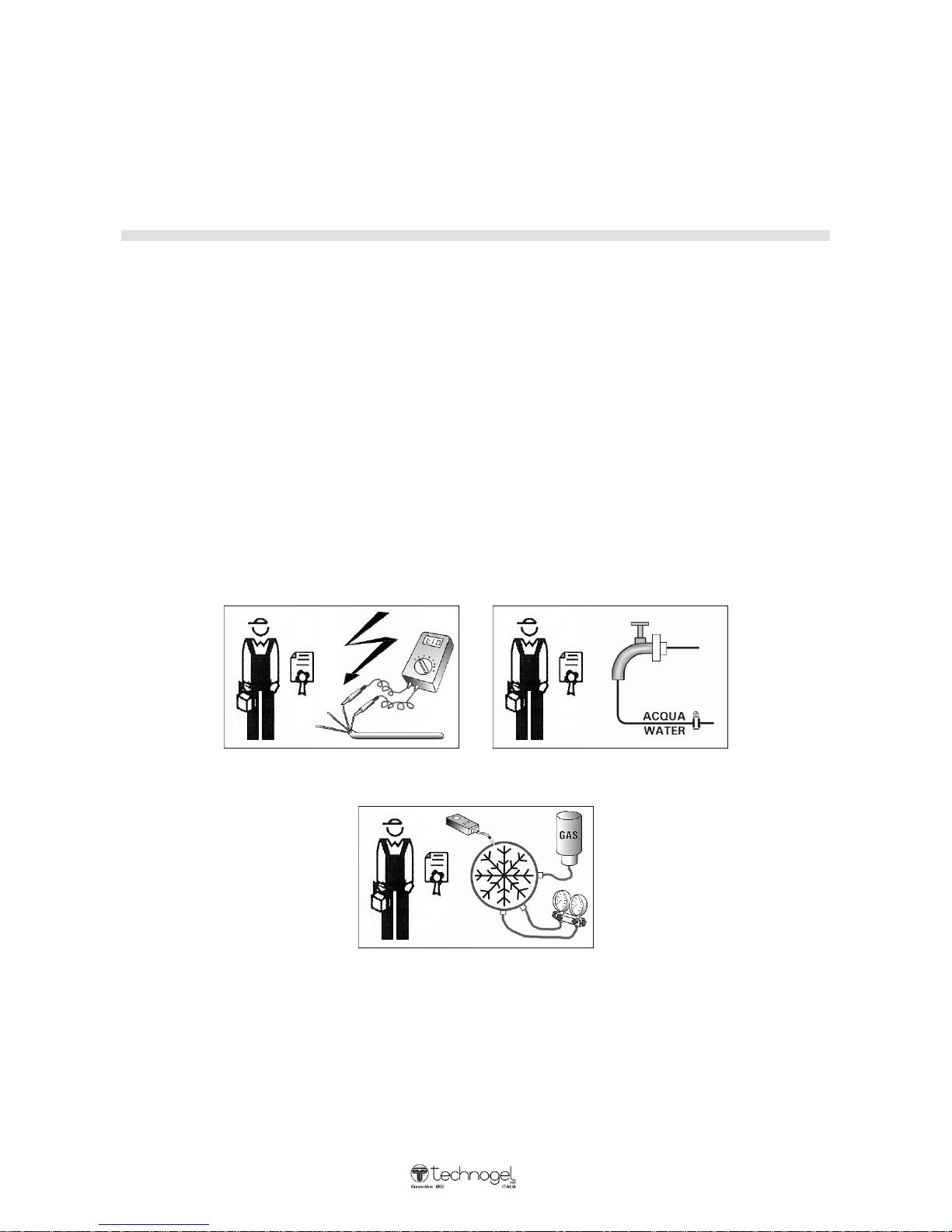
Persons qualified to carry out the work depending on the type of work involved
Please note the symbols given at the side of each operation described for installation, use and
maintenance:
= Technician = User
Where the symbol of the Technician is indicated (an electrician, plumber or mechanic) this means that
the operations described can be carried out exclusively by these people. If the user attemps to carry
out these operations this could prove dangerous and he/she must refrain from doing so.
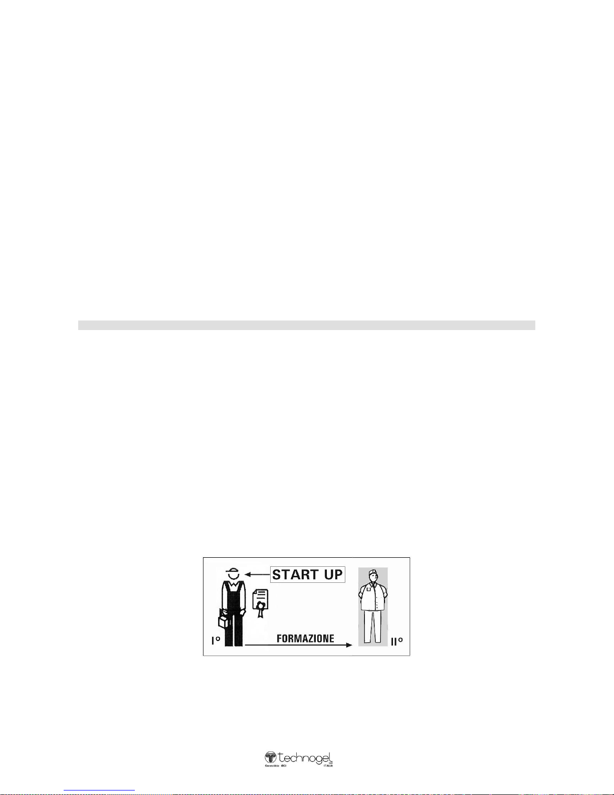
Installation and first start-up
The installation and first startup of this machine must be carried out by a TECHNOGEL
technician or one with TECHNOGEL authorization.
TECHNOGEL spa DECLINES ALL LIABILITY FOR INSTALLATIONS OR
STARTUPS CARRIED OUT BY UNAUTHORIZED PERSONS.
C:\Documents and Settings\mconti.TECHNOGEL-USA\My Documents\MACCHINE\ARTESAN\ART
MANUALS\Mantegel\Inglese\MG 2V Istruzioni Inglese 01-08.doc
4
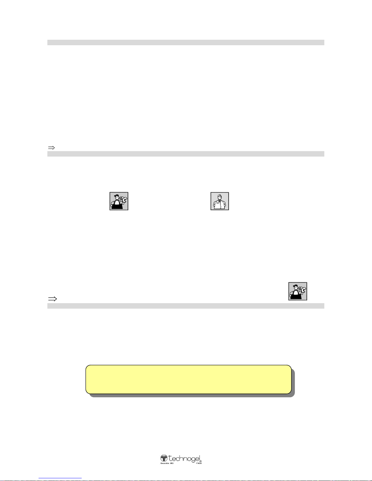
How to unpack the machine
GROSS WEIGHT A B C
MANTEGEL 20 = KG. 280 mm. 730 1030 1730
MANTEGEL 30 = KG. 310 mm. 730 1030 1730
MANTEGEL 50 = KG. 355 mm. 730 1100 1730
MANTEGEL 70 = KG. 525 mm. 730 1320 1730
ATTENTION : DUE TO ITS NARROW AND HIGH SHAPE, THE MACHINE
MAY BE UNSTABLE DURING HOISTING.
Remove all the side and top wooden panels
Lift the machine using a fork lift truck, inserting the forks between the
machine base and the crate base
Under the crate base unscrew the four bolts that hold the machine
tightly in position
ATTENTION:
After removing these bolts, the base of the crate will drop to the
ground.
After removing the crate base, lower the fork lift truck and place the
machine on the ground.
The machine can now be moved by means of the handles.
THE TYPE OF WOOD USED FOR THE PACKING CRATE IS NATURAL SPRUCE,
NOT CHEMICALLY TREATED SO THAT IT CAN BE PERFECTLY RECYCLED.
C:\Documents and Settings\mconti.TECHNOGEL-USA\My Documents\MACCHINE\ARTESAN\ART
MANUALS\Mantegel\Inglese\MG 2V Istruzioni Inglese 01-08.doc
5
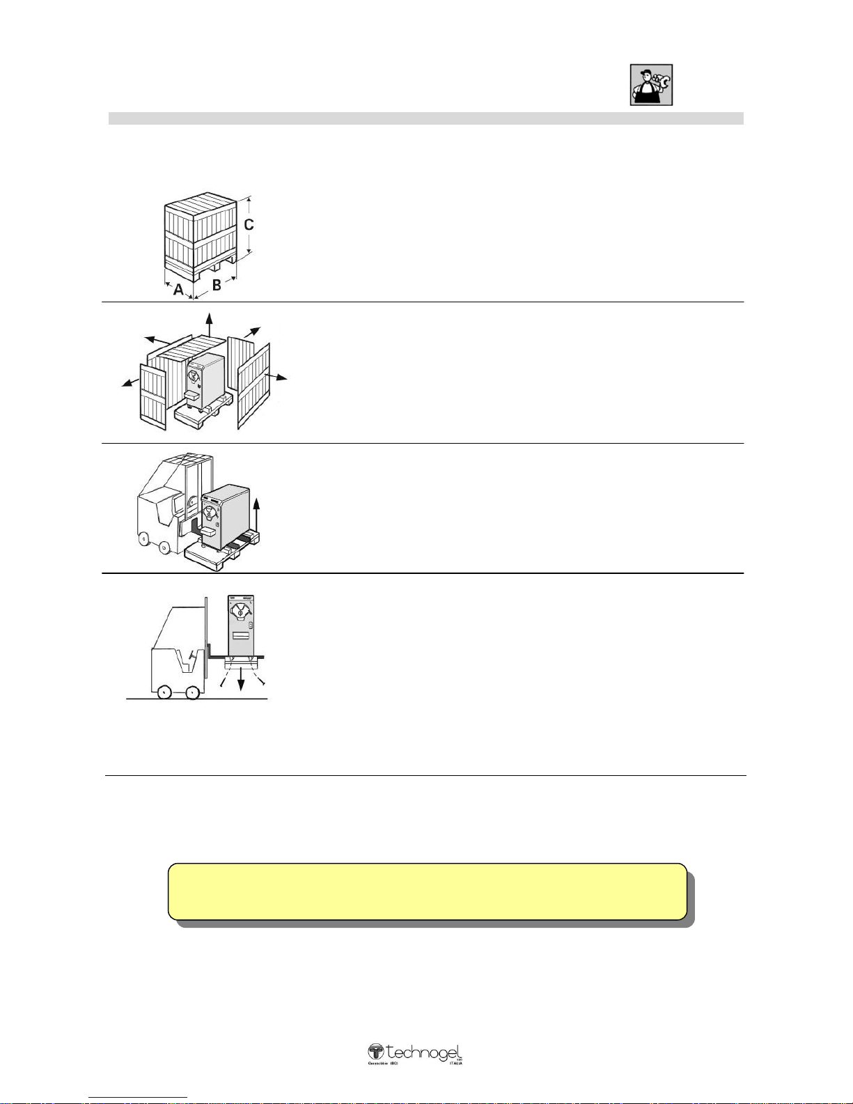
Hoisting the machine
NET WEIGHT A B C
MANTEGEL 20 = KG. 190 mm.490 620 1305
MANTEGEL 30 = KG. 220 mm.490 600 1330
MANTEGEL 50 = KG. 260 mm.490 740 1330
MANTEGEL 70 = KG. 435 mm.490 940 1400
ATTENTION: DUE TO ITS NARROW AND HIGH SHAPE, THE MACHINE
MAY BE UNSTABLE DURING HOISTING.
Lift the machine using a fork lift truck, inserting the forks from the side,
between the front and rear wheels.
Hoist the machine with belts near the front and rear wheels (as in
drawing).
The tie rod lifting the machine must be at the exact centre of the
machine.
Move the machine by holding the flange handle in one hand and the
corner of the machine in the other.
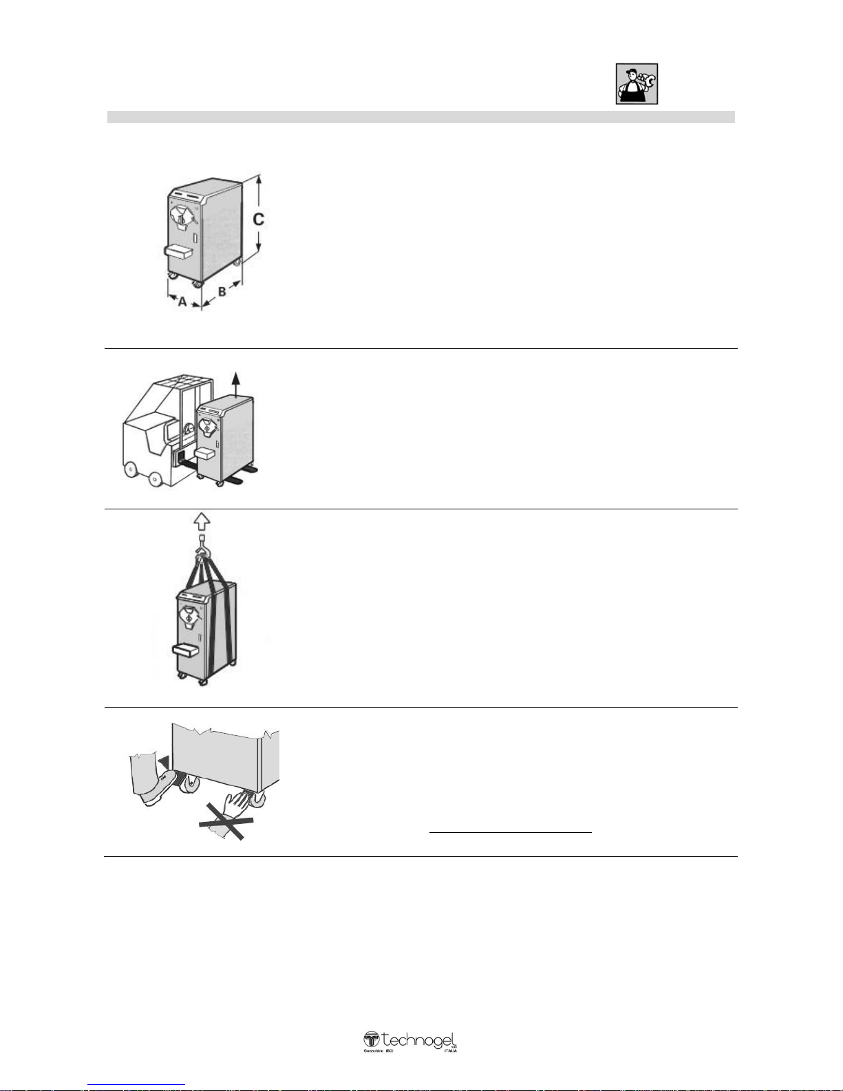
After positioning the machine, use your feet to lock with the front wheel
brakes.
NEVER USE YOUR HANDS
C:\Documents and Settings\mconti.TECHNOGEL-USA\My Documents\MACCHINE\ARTESAN\ART
MANUALS\Mantegel\Inglese\MG 2V Istruzioni Inglese 01-08.doc
6
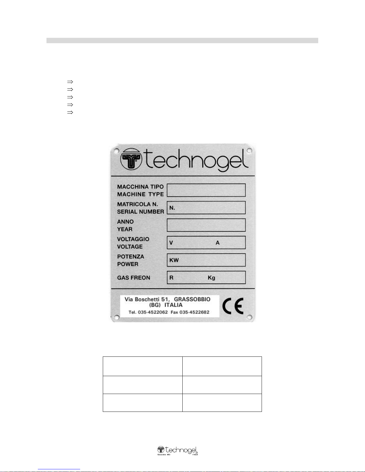
Machine identification
Every machine is given a plate bearing:
machine type
electrical power
serial number
gas type and quantity
voltage and hertz ratings
This plate is found at the back of the machine. Below is the serial plate for this machine.
When ordering spare parts and requesting technical assistance, always quote the information given on
the serial plate:
MACHINE TYPE
MANTEGEL
SERIAL NUMBER
VOLTAGE
VOLT HZ
C:\Documents and Settings\mconti.TECHNOGEL-USA\My Documents\MACCHINE\ARTESAN\ART
MANUALS\Mantegel\Inglese\MG 2V Istruzioni Inglese 01-08.doc
7
P
P
O
O
S
SIITTII
O
O
N
N
E
E
M
M
E
E
N
NTT
M
M
A
A
C
C
H
HII
N
N
E
E
C
C
O
O
N
N
D
D
E
E
N
N
S
S
E
E
R
R FF
O
O
R
R
W
W
A
ATT
E
E
R
R
CCO
ONNNNEECCTTII
O
ONN
W
WAATTEERR EENNDD
EELLEECCTTRRIICCAALL
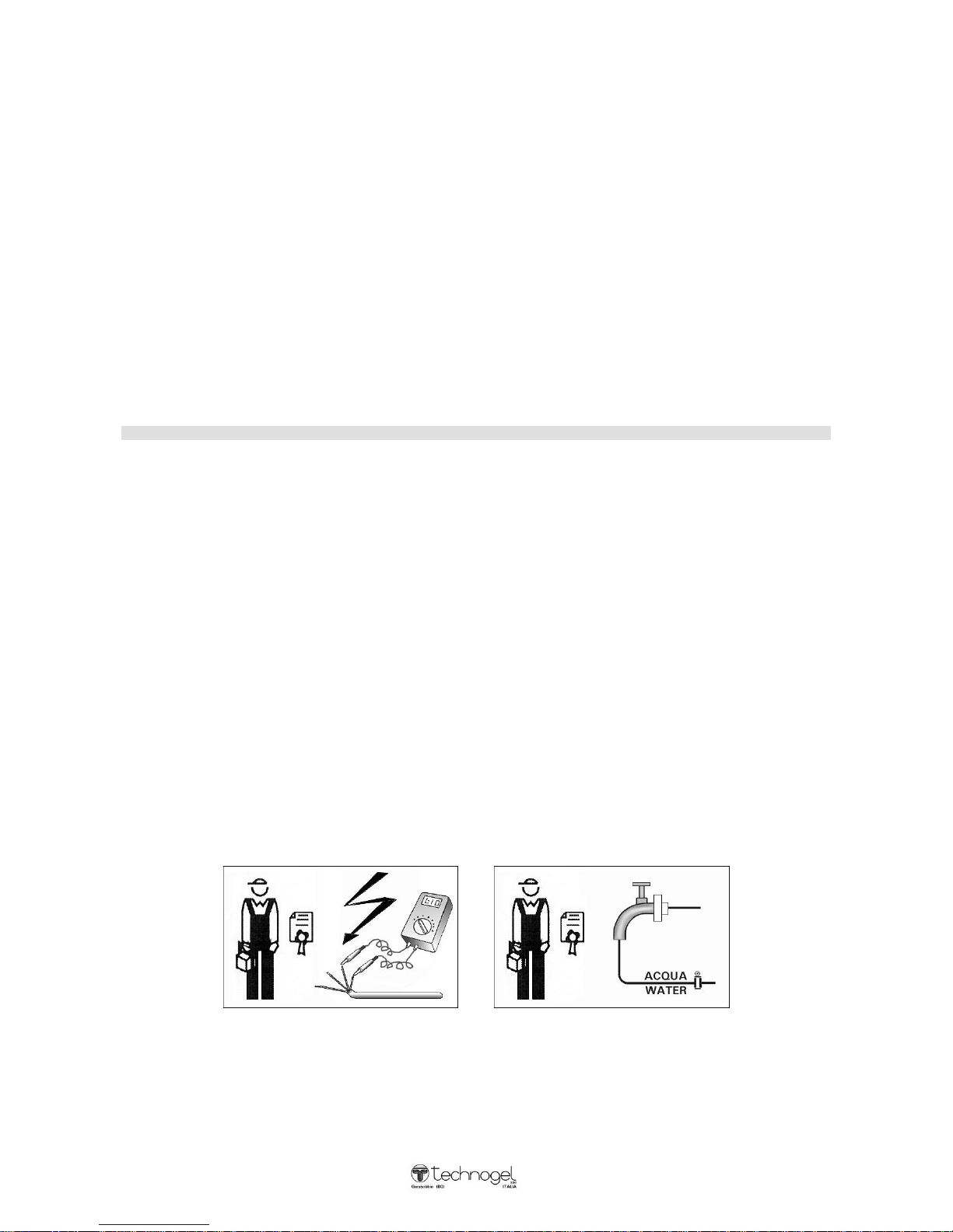
technician qualificate:
ELECTRICIAN PLUMBER
C:\Documents and Settings\mconti.TECHNOGEL-USA\My Documents\MACCHINE\ARTESAN\ART
MANUALS\Mantegel\Inglese\MG 2V Istruzioni Inglese 01-08.doc
8
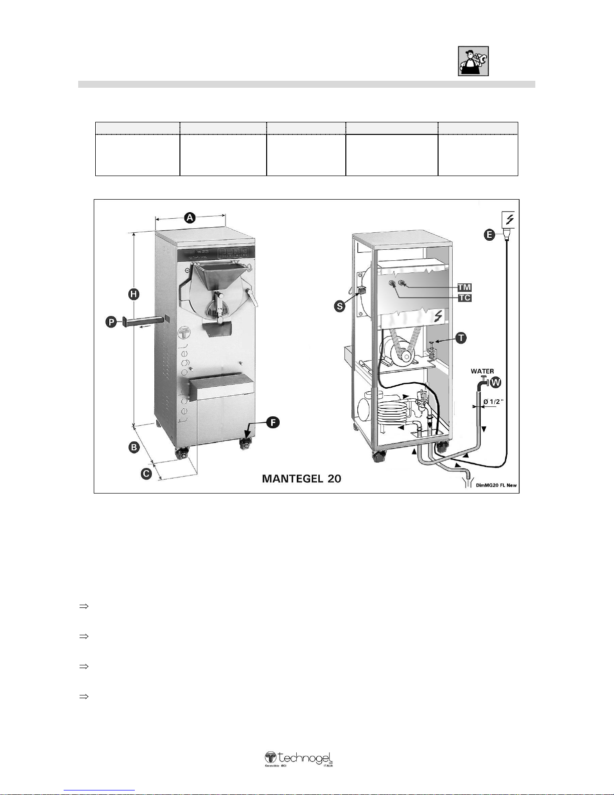
Dimensions and different facilities: MANTEGEL 20
Dimensions and weight:
A – width
B – depth
C
H – height
Weight
19 ” 3/8
490 mm.
24 ” 7/16
620 mm.
7” 7 /8
200 mm.
51 ” 3/8
1305 mm.
419 Lb.
190 Kg.
WARNING:
For the good functioning, the machine does not have to be anchored to the floor, neither some
particular technical precaution are to be taken to limit the vibration transmission.
The installation requires the following operations:
Around t he machine perimeter, leave an operative space of at least 10” (25 cm) necessary t o carry
out the works smoothly.
Make sure the machine is steady by blocking the brakes (F) of the front wheels using the feet (DO
NOT USE THE HANDS).
Connect the hidro-system with the w ater inlet and outlet (see above picture point W). For the
pressure and consumption data refer to page 12 (MANTEGEL 20).
Connect the electric system (see above picture point E). For the power and absorption data refer to
page 10 (Table A - MANTEGEL 20).
C:\Documents and Settings\mconti.TECHNOGEL-USA\My Documents\MACCHINE\ARTESAN\ART
MANUALS\Mantegel\Inglese\MG 2V Istruzioni Inglese 01-08.doc
9
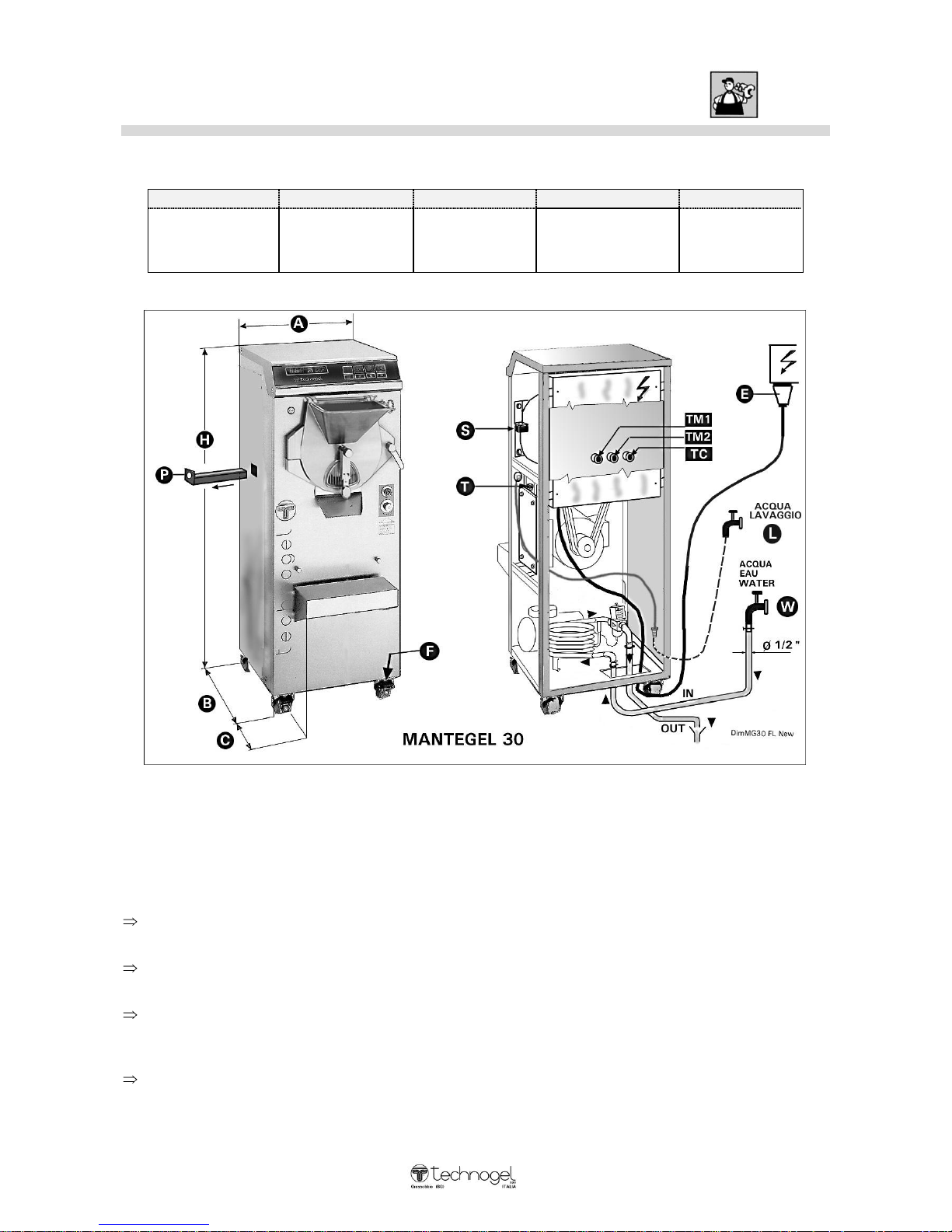
Dimensions and different facilities: MANTEGEL 30
Dimensions and weight:
A – width
B – depth
C
H – height
Weight
19 ” 3/8
490 mm.
24 ” 7/16
620 mm.
7” 7 /8
200 mm.
52 ” 3/8
1330 mm.
485 Lb.
220 Kg.
WARNING:
For the good functioning, the machine does not have to be anchored to the floor, neither some
particular technical precaution are to be taken to limit the vibration transmission.
The installation requires the following operations:
Around the machine perimeter, leave an operative space of at least 10” (25 cm) necessary to carry
out the works smoothly.
Make sure the machine is steady by blocking the brakes (F) of the front wheels using the feet (DO
NOT USE THE HANDS).
Connect the hidro-system with the w ater inlet and outlet (see above picture point W). For the
pressure and consumption data refer to page 12(MANTEGEL 30). Connect, also, the washing
water (L) cold or hot according to the availability.
Connect the electric system (see above picture point E). For the power and absorption data refer to
page 10 (Table A - MANTEGEL 30).
C:\Documents and Settings\mconti.TECHNOGEL-USA\My Documents\MACCHINE\ARTESAN\ART
MANUALS\Mantegel\Inglese\MG 2V Istruzioni Inglese 01-08.doc
10
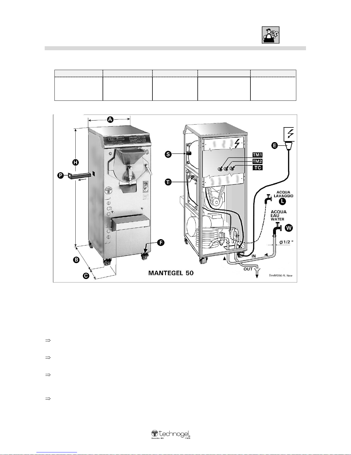
Dimensions and different facilities: MANTEGEL 50
Dimensions and weight:
A – width
B – depth
C
H – height
Weight
19 ” 3/8
490 mm.
29 ” 1/2
750 mm.
7” 7 /8
200 mm.
52 ” 3/8
1330 mm.
640 Lb.
290 Kg.
WARNING:
For the good functioning, the machine does not have to be anchored to the floor, neither some
particular technical precaution are to be taken to limit the vibration transmission.
The installation requires the following operations:
Around t he machine perimeter, leave an operative space of at least 10” (25 cm) necessary t o carry
out the works smoothly.
Make sure the machine is steady by blocking the brakes (F) of the front wheels using the feet (DO
NOT USE THE HANDS).
Connect the hidro-system with the w ater inlet and outlet (see above picture point W). For the
pressure and consumption data refer to page 12 (MANTEGEL 50). Connect, also, the washing
water (L) cold or hot according to the availability.
Connect the electric system (see above picture point E). For the power and absorption data refer to
page 10 (Table A - MANTEGEL 50).
C:\Documents and Settings\mconti.TECHNOGEL-USA\My Documents\MACCHINE\ARTESAN\ART
MANUALS\Mantegel\Inglese\MG 2V Istruzioni Inglese 01-08.doc
11
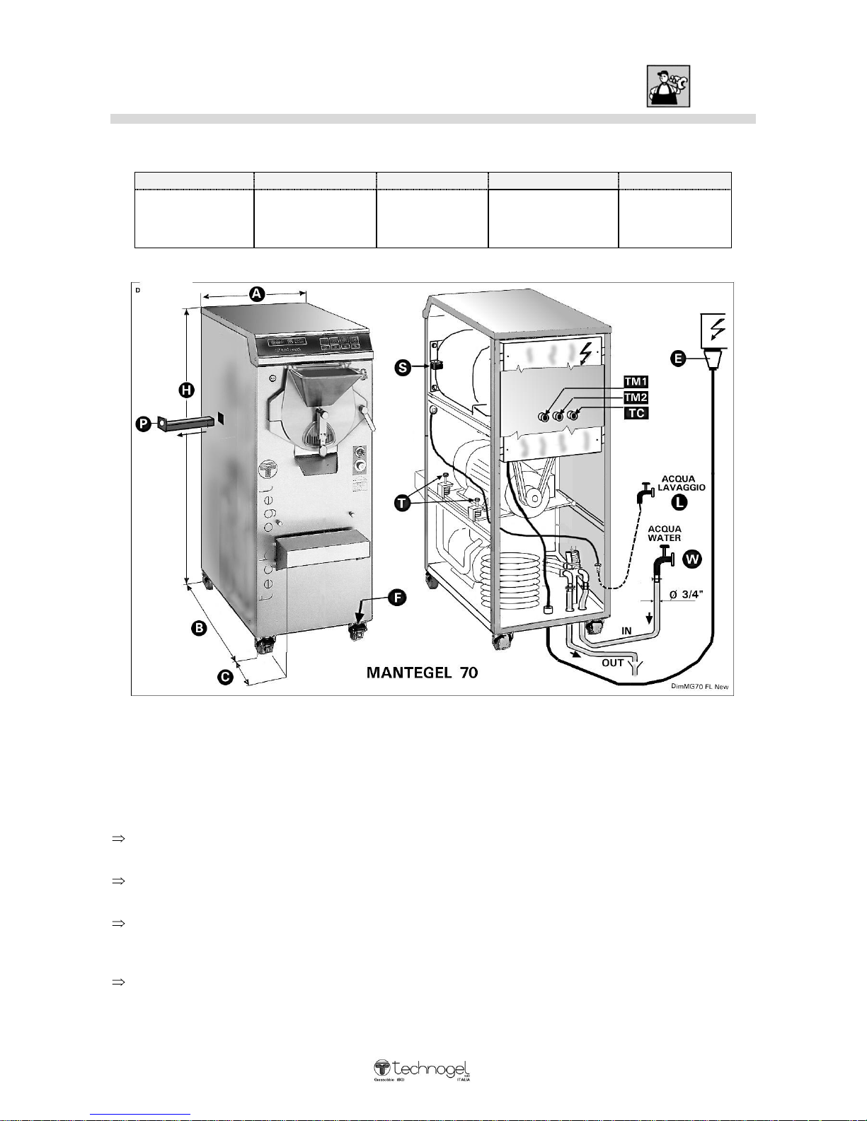
Dimensions and different facilities: MANTEGEL 70
Dimensions and weight:
A – width
B – depth
C
H – height
Weight
19 ” 3/8
490 mm.
37”
940 mm.
7” 7 /8
200 mm.
55”
1400 mm.
960 Lb.
435 Kg.
WARNING:
For the good functioning, the machine does not have to be anchored to the floor, neither some
particular technical precaution are to be taken to limit the vibration transmission.
The installation requires the following operations:
Around t he machine perimeter, leave an operative space of at least 10” (25 cm) necessary t o carry
out the works smoothly.
Make sure the machine is steady by blocking the brakes (F) of the front wheels using the feet (DO
NOT USE THE HANDS).
Connect the hidro-system with the w ater inlet and outlet (see above picture point W). For the
pressure and consumption data refer to page 12 (MANTEGEL 70). Connect, also, the washing
water (L) cold or hot according to the availability.
Connect the electric system (see above picture point E). For the power and absorption data refer to
page 10 (Table A - MANTEGEL 70).
C:\Documents and Settings\mconti.TECHNOGEL-USA\My Documents\MACCHINE\ARTESAN\ART
MANUALS\Mantegel\Inglese\MG 2V Istruzioni Inglese 01-08.doc
12
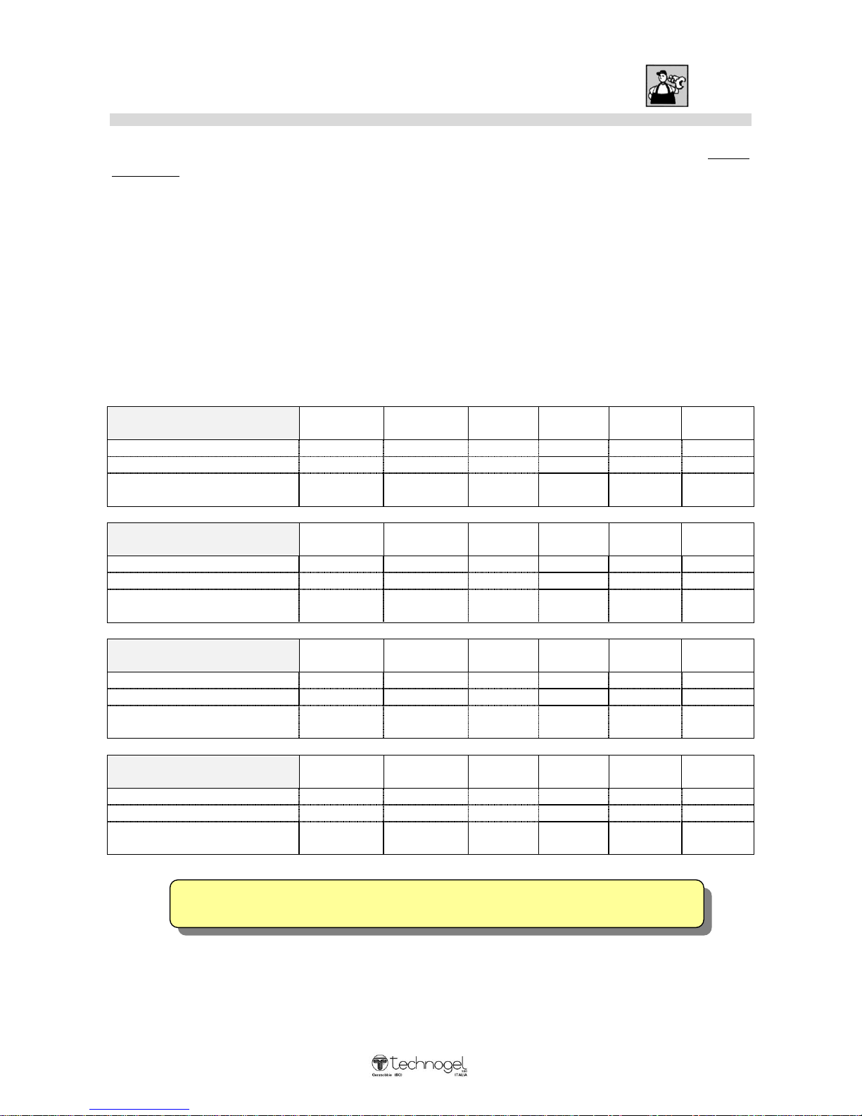
Electrics installation
The electrical installation, which the machine is connected to, must be carried out by a skilled
electrician according to regulations and observing the Laws in force. An efficient electrical
installation with earthing is the most important thing in order for your machine to work
perfectly.
Fit a suitable wall switch: we strongly recommend fitting an automatic differential switch. See table
(A) for power rating and absorption details.
Check taht the mains voltage rate is the same as the machine rating, shown on the serial number plate
(see page 5).
The power cable has 4 wires: the yellow/green wire is the earth wire, the other three are for the three
phases.
Table (A):
MANTEGEL 20
V.220
50HZ
V.220
60HZ
V.200
50/60HZ
V.380
50HZ
V.380
60HZ
V.415
50HZ
Total power KW
2,6
2,6
4
2,6
2,6
2,6
Max. absorp. A.
10,5
10,5
19
6,5
7,5
6,5
Power cable
Wires & section
4 x 2,5
mm²
4 x 2,5
mm²
4 x 4
mm²
4 x 1,5
mm²
4 x 2,5
mm²
4 x 1,5
mm²
MANTEGEL 30
V.220
50HZ
V.220
60HZ
V.200
50/60HZ
V.380
50HZ
V.380
60HZ
V.415
50HZ
Total power KW
4,2
4,2
4,2
4,2 4,2
Max. absorp. A.
11,2
11,2
19,5 7 8
6,5
Power cable
Wires & section
4 x 4
mm²
4 x 4
mm²
4 x 4
mm²
4 x 2,5
mm²
4 x 2,5
mm²
4 x 2,5
mm²
MANTEGEL 50
V.220
50HZ
V.220
60HZ
V.200
50/60HZ
V.380
50HZ
V.380
60HZ
V.415
50HZ
Total power KW
6 6 6
6
Max. absorp. A.
20
20 13 12
Power cable
Wires & section
4 x 6
mm²
4 x 6
mm²
4 x 4
mm²
4 x 4
mm²
MANTEGEL 70
V.220
50HZ
V.220
60HZ
V.200
50/60HZ
V.380
50HZ
V.380
60HZ
V.415
50HZ
Total power KW
11,2
11,2
11,2
11,2
11,2
Max. absorp. A.
36
36
45
21 20
Power cable
Wires & section
4 x 10
mm²
4 x 10
mm²
4 x 10
mm²
4 x 6
mm²
4 x 6
mm²
TECHNOGEL CANNOT BE HELD LIABLE FOR ANY DAMAGE ARISING FROM
INCORRECT INSTALLATION OR MAINS DEFECTS.
C:\Documents and Settings\mconti.TECHNOGEL-USA\My Documents\MACCHINE\ARTESAN\ART
MANUALS\Mantegel\Inglese\MG 2V Istruzioni Inglese 01-08.doc
13
Water connection
The refrigeration system has a water-cooled condenser. A connection for the hot or cold water pipe
exists. It is useful for washing the machine. Its tap and nozzle are in the front of the machine.
Connect the mains hose to the fitting that reads " ENTRATA ACQUA- WATER INLET ".
The drain hose must be connected to the fitting that reads " USCITA ACQUA-WATER OUTLET ".
The connection plates and fittings are inside the machine: to access these, remove the rear panel.
To connect the machine to the mains, we recommend using a rubber hose suitable for up to 10 bars
with an inside diameter of about 15 mm (matching the fittings supplied with the machine).
If, for any reason, the plates indicating water inlet and outlet are illegible, please note that the water
inlet hose is fitted to the pressure-switch valve.
WATER PRESSURE AND CONSUMPTION
If the machine is using mains w ater, check that the incoming w ater has a pressure of at least 1 bar.
If the water pressure is more than 5 bar, fit a pressure reducer to the system, to reduce this to 4 bar.
Average water consumption (when the refrigerating unit is on) is:
- MANTEGEL 20 = 80/100 litres/hours*
- MANTEGEL 30 = 100/190 litres/hour*
- MANTEGEL 50 = 150/250 litres/hours*
- MANTEGEL 70 = 300/450 litres/hours*
* depending on the temperature of the incoming water.
If the water contains impurities, fit a purifying filter to avoid scaling and/or damage to the
pressure-switch valve.

C:\Documents and Settings\mconti.TECHNOGEL-USA\My Documents\MACCHINE\ARTESAN\ART
MANUALS\Mantegel\Inglese\MG 2V Istruzioni Inglese 01-08.doc
14
C:\Documents and Settings\mconti.TECHNOGEL-USA\My Documents\MACCHINE\ARTESAN\ART
MANUALS\Mantegel\Inglese\MG 2V Istruzioni Inglese 01-08.doc
15
M
M
A
A
C
C
H
HII
N
N
E
E
P
P
O
O
S
SIITTII
O
O
N
NII
N
N
G
G
C
C
O
O
N
N
D
D
E
E
N
N
S
S
E
E
R
R FF
O
O
R
R
A
AII
R
R
O
O
A
AII
R
R //
W
W
A
ATT
E
E
R
R
CCO
ONNNNEECCTTII
O
ONNSS
Technician qualificate:
ELECTRICIAN PLUMBER
IF The machine works with isolate condenser,you’ ll have to contact the:
REFRIGERATOR TECHNICIAN
C:\Documents and Settings\mconti.TECHNOGEL-USA\My Documents\MACCHINE\ARTESAN\ART
MANUALS\Mantegel\Inglese\MG 2V Istruzioni Inglese 01-08.doc
16
TECHNOGEL spa CANNOT BE HELD RESPONSIBLE FOR ANY DAMAGE CAUSED BY
INCORRECT POSITIONING OF THE MACHINE IN AN UNSUITABLE PLACE. THE
COMPANY IS ALSO UNABLE TO ASSUME ANY RESPONSIBILITY FOR INADEQUATE
PERFORMANCE OF THE MACHINE OWING TO OPERATING CONDITIONS BEING
BEYOND THE LIMITS OF ACCEPTABILITY.
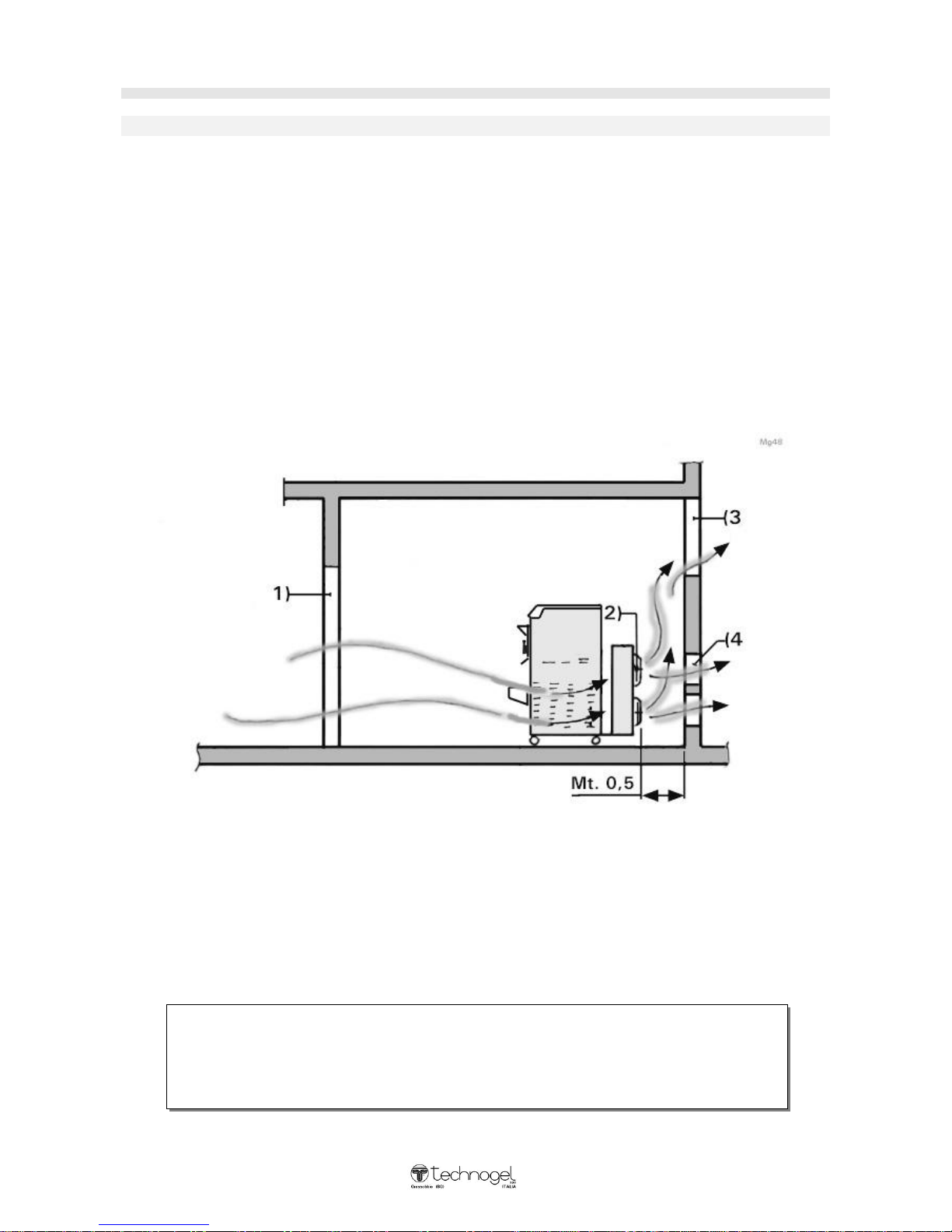
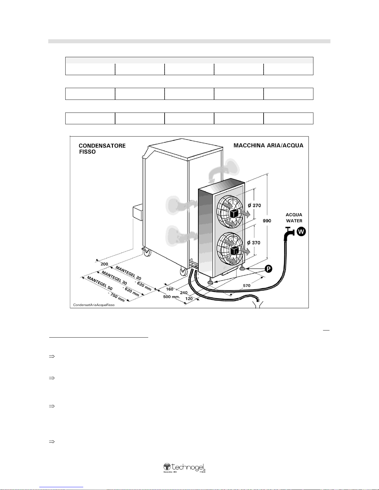
Positioning of machine with fixed air condenser
VALID FOR MACHINES WITH EITHER AIR CONDENSATION OR AIR/WATER COMBINED
It is extremely important that the machine should be installed in a spacious room with doors
and windows so the air heated by the machine can be changed regularly.
The rear of the machine must be place at a distance of at least 0.5 metres from the wall.
During operation of the machine, the doors and windows in the room must be left open
otherwise the air heated by the machine will become extremely hot and could reach
temperatures of around 50°C. If the machine is allowed to operate in these conditions the
main components (refrigerator compressor and turbine motor) could well overheat over the
long term and this could jeopardize correct operation of the machine and cause damage which
would be costly to repair. It would also mean an increase in running costs owing to the high
consumption of elect ricity w hile the machine’ s performance w ould be reduced by 50%.
IDEAL POSITIONING OF THE MACHINE
As shown in the diagram, the air coming in through the door (1) is sucked in and heated
during condensation of the ventilators (2) and is pushed in the direction of the window (3)
and thus outside.
The ideal solution, though not always easy to put into practice, is to make holes in the wall
(4) opposite the ventilators (2). The air can therefore flow out freely without any problem and
the machine’ s performance will alw ays be excellent .
C:\Documents and Settings\mconti.TECHNOGEL-USA\My Documents\MACCHINE\ARTESAN\ART
MANUALS\Mantegel\Inglese\MG 2V Istruzioni Inglese 01-08.doc
17
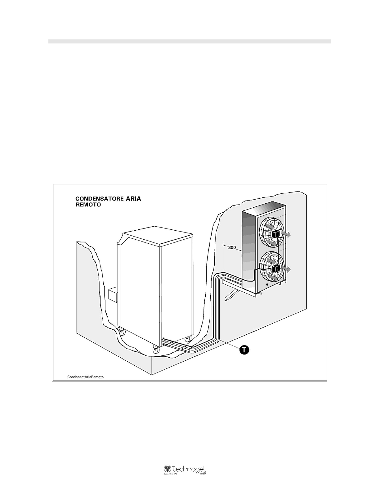
Positioning of the machine with remote air condenser
In order to combat problems of overheating of the air, whenever possible the remote air condenser
should be mounted.
CAUTION:
Copper or flexible piping (T) transporting the refrigerant gas from the machine to the condenser and
vice versa,
Should not exceed 4 metres in length.
The condenser must be fixed to wall brackets positioned high up so that they are beyond the reach of
people of average height.
As illustrated in the diagram, the condenser must be positioned at least 200 mm from the wall so that
air can be sucked in without any problem. It is also advisable to install protective roofing over the
equipment to protect it from rain water.
with remote air condenser
The machine must be installed by a Refrigeration Technician who after connecting the equipment will
check that the quantity of gas inside the machine is correct for optimum operation.
C:\Documents and Settings\mconti.TECHNOGEL-USA\My Documents\MACCHINE\ARTESAN\ART
MANUALS\Mantegel\Inglese\MG 2V Istruzioni Inglese 01-08.doc
18
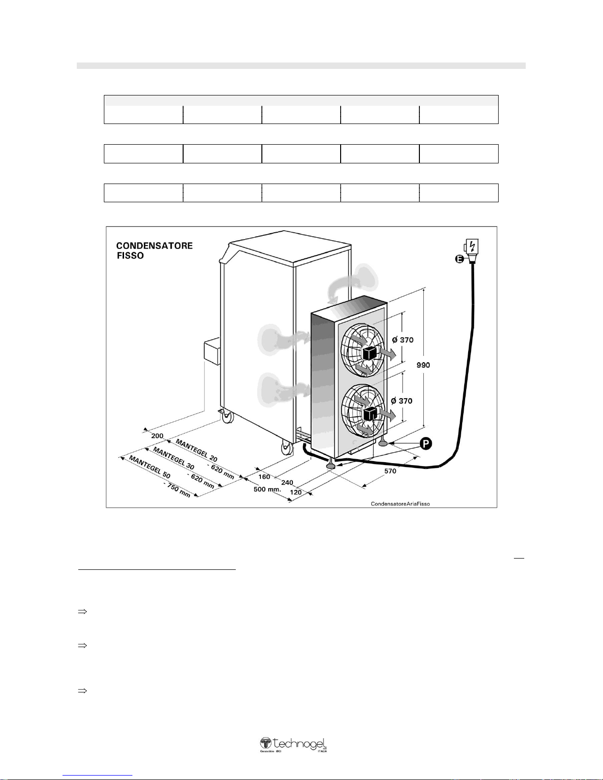
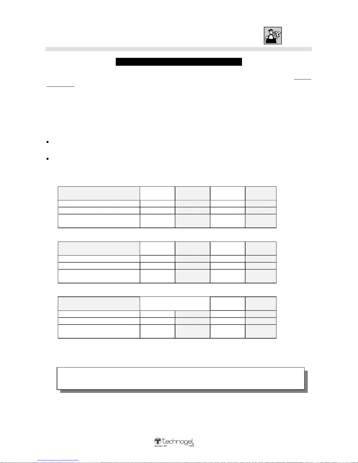
Cooling Machine fixed
Dimension / Weigh MANTEGEL 20 Air
A- Width
B – Depth
C – Console Table
H – Height
Weight
490 mm
1120 mm
200 mm.
1305
220 Kg.
Dimension / Weigh MANTEGEL 30 Air
490 mm
1120 mm
200 mm.
1305
250 Kg.
Dimension / Weigh MANTEGEL 50 Air
490 mm
1300 mm
200 mm.
1305
290 Kg.
WARNINGS:
After positioning the machine and locking the front wheels by pressing on the brake with the feet (do
not use the hands for this operation), check that the feet (P) both rest on the floor. If the feet (P) are
not level, during operation the condenser could move around owing to movement of the ventilators.
If the machine operates in contact with other machines, make sure there is a space of at least 25
cm between them.
Carry out the electrical connections of the machine and make sure that the electric cable (E) comes
from above and is not laid on the floor where it could be crushed. For data on power and
absorption please see page 22 Table A under the specific machine reference.
For the MANTEGEL 30 and MANTEGEL 50 machines, it is possible to connect hot or cold water
for washing purposes to the rear of the machine.
C:\Documents and Settings\mconti.TECHNOGEL-USA\My Documents\MACCHINE\ARTESAN\ART
MANUALS\Mantegel\Inglese\MG 2V Istruzioni Inglese 01-08.doc
19
Cooling Machine Arranged air water
Dimension / Weigh MANTEGEL 20 Air / Water
A- Width
B – Depth
C – Console Table
H – Height
Weight
490 mm
1120 mm
200 mm.
1305
230 Kg.
Dimension / Weigh MANTEGEL 30 Air / Water
490 mm
1120 mm
200 mm.
1305
260 Kg.
Dimension / Weigh MANTEGEL 50 Air / Water
490 mm
1300 mm
200 mm.
1305
300 Kg.
FIXED COOLING AIR / WATER MACHINE
WARNINGS:
After positioning the machine and locking the front wheels by pressing on the brake with the feet (do
not use the hands for this operation), check that the feet (P) both rest on the floor. If the feet (P) are
not level, during operation the condenser could move around owing to movement of the ventilators.
If the machine operates in contact with other machines, make sure there is a space of at least 25
cm between them.
Carry out the electrical connections of the machine and make sure that the electric cable (E) comes
from above and is not laid on the floor where it could be crushed. For data on power and
absorption please see page 22 Table A under the specific machine reference.
Connect the water supply (W) to the machine with inlet and outlet for the condensation from the
refrigerating unit. For instructions on how to connect the machine, please see pages 8, 9 or 10
depending on the type of machine. For data on pressure and consumption, please see page 15.
(Page 19 only).
For the MANTEGEL 30 and MANTEGEL 50 machines, it is possible to connect hot or cold water
for washing purposes to the rear of the machine.
C:\Documents and Settings\mconti.TECHNOGEL-USA\My Documents\MACCHINE\ARTESAN\ART
MANUALS\Mantegel\Inglese\MG 2V Istruzioni Inglese 01-08.doc
20
TECHNOGEL spa CANNOT ASSUME ANY RESPONSIBILITY FOR ACCIDENTS
CAUSED BY IMPROPER INSTALLATION OR FAULTY WIRING
Electric installation
COOLING MACHINE AIR O AIR / WATER
The electrical installation, which the machine is connected to, must be carried out by a skilled
electrician in compliance with regulations and the Laws in force. An efficient electrical
installation with earthing is most important to ensure your machine works perfectly.
Fit a suitable wall switch: we strongly recommend fitting an automatic differential switch. See table
(A) for power rating and absorption details.
Check that the mains voltage is the same as the machine rating, shown on the serial number plate
(see page 6).
When the cable has 4 wires, the yellow/green wire is the earth and the other three are the three
phases.
When the cable has 5 wires, the yellow/green wire is the earth - the blue wire is neutral - the other
three are the three phases.
- TABLE -A-
MANTEGEL 20 Air
V.220
50 HZ
V.220
60 HZ
V.400
50 HZ
V.380
60 HZ
Total power KW.
3 3 3
Absorbtion edge A.
12
12 8
Wire line
Branch screw
4 x 2,5mm²
4 x 2,5mm²
4 x 1,5mm²
MANTEGEL 30 Air
V.220
50 HZ
V.220
60 HZ
V.400
50 HZ
V.380
60 HZ
Total power KW.
3,2
3,2
3,2
Absorbtion edge A.
13
13
8,5
Wire line
Branch screw
4 x 4mm²
4 x 4mm²
4 x 2,5mm²
MANTEGEL 50 Air
V.220
50 HZ
V.220
60 HZ
V.400
50 HZ
V.380
60 HZ
Total power KW.
5,2
5,2
5,2
Absorbtion edge A.
21
21
14,5
Wire line
Branch screw
4 x 6mm²
4 x 6mm²
4 x 4mm²

C:\Documents and Settings\mconti.TECHNOGEL-USA\My Documents\MACCHINE\ARTESAN\ART
MANUALS\Mantegel\Inglese\MG 2V Istruzioni Inglese 01-08.doc
21
ACCEPTABLE AND
UNACCEPTABLE USAGE
C:\Documents and Settings\mconti.TECHNOGEL-USA\My Documents\MACCHINE\ARTESAN\ART
MANUALS\Mantegel\Inglese\MG 2V Istruzioni Inglese 01-08.doc
22
ACCEPTABLE AND UNACCEPTABLE USAGE
All whipping machines in TECHNOGEL's MANTEGEL series have been designed exclusively
for mixing ice-cream.
Use of these machines for any products other than those intended is entirely at the
Customer's own risk.
Machine operation conditions
Below are the minimum and maximum mix loads that the different machines can work (espressed in
litres of mix per load).
minimum load
maximum load
MANTEGEL 20
2 litres
4 litres
MANTEGEL 30
3 litres
6 litres
MANTEGEL 50
3 litres
8 litres
MANTEGEL 70
7 litres
15 litres
WE STRONGLY RECOMMEND RESPECTING THESE MINIMUM AND
MAXIMUM LOADS TO ENSURE THAT YOUR MACHINE PRODUCES
GOOD QUALITY ICE-CREAM IN ABSOLUTE SAFETY.
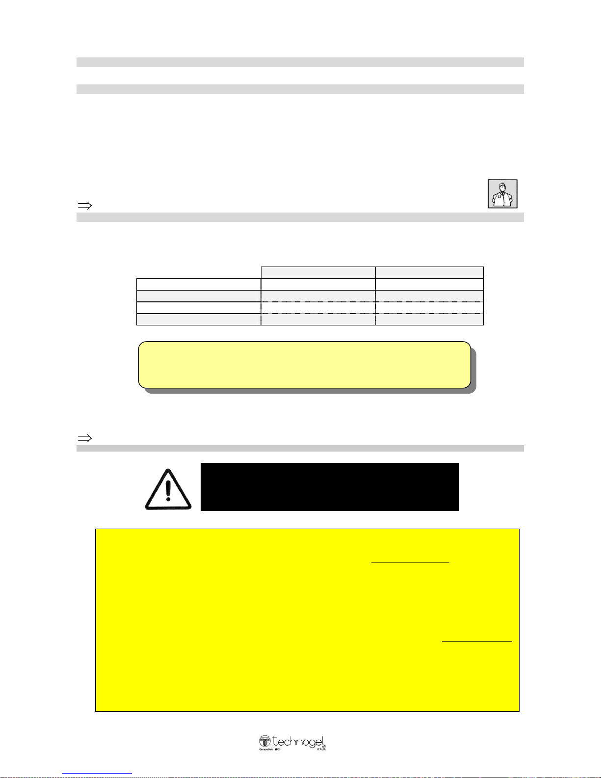
Initial start-up
CAUTION IMPORTANT
TO CARRY OUT INITIAL START-UP, PRESS THE “ START”
BUTTON AND THEN WAIT FOR AT LEAST 60 MINUTES BEFORE
ACTIVATING THE REFRIGERATOR COMPRESSOR.
IF THE MACHINE IS DISCONNECTED FROM THE POWER SUPPLY
FOR ONE DAY OR MORE, AFTER PRESSING THE “ START”
BUTTON, IT IS NECESSARY TO WAIT FOR AT LEAST 60 MINUTES
BEFORE ACTIVATING THE REFRIGERATOR COMPRESSOR.
IF THE MACHINE IS NEVER DISCONNECTED FROM THE POWER
SUPPLY NO WAITING PERIOD IS NECESSARY.
C:\Documents and Settings\mconti.TECHNOGEL-USA\My Documents\MACCHINE\ARTESAN\ART
MANUALS\Mantegel\Inglese\MG 2V Istruzioni Inglese 01-08.doc
23
TECHNOGEL CANNOT BE HELD LIABLE FOR DAMAGE AS A RESULT
OFTAMPERING WITH THE MACHINE SAFETY DEVICES.
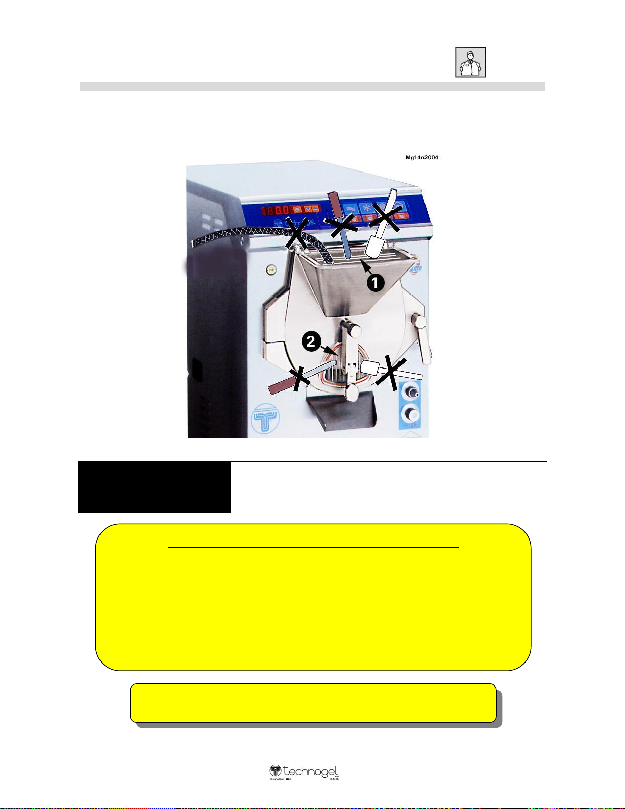
What you must not do while the machine is operating:
Never introduce foreing bodies in the hopper when this is in use, eg.
scrapers -
knives - rubber hose, etc., as these can damage the machine and may
injure the operator.
Never put scrapers or knives between the bars in the exit while the ice-
cream is flowing out.
Safety warning
Before starting the machine, verify if the safety devices (1) (hopper protection grill) and (2)
(exit protection grill) are mounted and working.
WARNING
Tampering or reducing the safety devices (1) and (2),
can cause serious injuries to the operator

C:\Documents and Settings\mconti.TECHNOGEL-USA\My Documents\MACCHINE\ARTESAN\ART
MANUALS\Mantegel\Inglese\MG 2V Istruzioni Inglese 01-08.doc
24
C:\Documents and Settings\mconti.TECHNOGEL-USA\My Documents\MACCHINE\ARTESAN\ART
MANUALS\Mantegel\Inglese\MG 2V Istruzioni Inglese 01-08.doc
25
FFUUNNCCTTIIO
ONNSS
O
OFF TTHHEE
M
MAACCHHIINNEE
W
WIITTHH PPRREELLII
M
MIINNAARRYY CCHHEECCKKIINN
G
G
AANNDD CCO
ONNTTRR
O
OLL
The explanation of the machine functions, preliminary checking and controls should be carried
out by TECHNOGEL’ s Technician together w ith the Operator who will be using the machine
after appropriate training has been given.

C:\Documents and Settings\mconti.TECHNOGEL-USA\My Documents\MACCHINE\ARTESAN\ART
MANUALS\Mantegel\Inglese\MG 2V Istruzioni Inglese 01-08.doc
26
Console control functions – GEL – batch freezing
Instructions for setting the texture of the ice-cream:
To set the ice-cream hardness, first connect the control console to the power supply by pressing the
START button. The pushbutton must be lit up.
The number (expressed as a percentage)
which appears on the display (2), indicates
the force exerted by the turbine in mixing the
ice-cream and can vary from 0% (mixer
turbine motor stopped) to 60% (motor in
operation with liquid mixture) to 100%
(maximum force the motor can produce).
This number varies (the value rises) the thicker the texture of the ice-cream: i.e. the harder the ice-cream, the
higher the number indicated on the display .
This value w hen the ice-cream is ready can range from 70 to 100% depending on the model (MG20 –
MG30 – MG50 – MG70). The right value for your machine will be obtained by experimenting with a first
freeze-batch.
Whilst holding down key (1), press key (4) until the display gives the maximum value (100). Carry out a “ batch
freeze” and w hen the ice--cream is to your liking look on the display to see the number indicated (e.g. 78).
While the machine is in operation, hold down key (1) and press key (3) so that the value on the display,
regulated on 100, drops to tally w ith the number read for the ice-cream prepared (78). The LED (5) will flash
intermittently for 1.5 seconds and immediately afterwards you will hear an alarm sound (different from the
pasteurization alarm). It will sound for 10 seconds to warn you that the ice-cream is ready for extraction (while
the alarm is sounding the freezing stops whereas stirring continues). If the ice-cream is not extracted the
machine will start to freeze again and will once again reach the hardness value set. At this point it will stop,
the alarm will sound again as described above, and the process will then continue indefinitely.
This is the right texture for your ice-cream and the machine will then repeat it endlessly, without any need to
reset it each time.
If during subsequent batch freezings the ice-cream does not seem hard enough, or is too hard, the hardness
value can be regulated even when the machine is in operation. Hold down key (1), increase the value to (80)
using key (4) (to get harder ice-cream) or decrease to 76 using key (3) (to get softer ice-cream).
Generally speaking it is normal for the hardness
parameters to vary slightly from cream flavoured
ice-cream to fruit ice-cream and from minimum to
maximum quantities frozen.
CAUTION:
When varying the hardness never change the value
by more than 2% at a time.
Depending on the model of machine (MG20 –
MG30 – MG50 – MG70) or the type of mix
which is to be frozen , it is possible and quite
normal for a value to be set which is too high for
the machine to reach, even though the value is
below 100. If this occurs, read the maximum
value achieved and set this value as the hardness
for that particular type of ice-cream.
C:\Documents and Settings\mconti.TECHNOGEL-USA\My Documents\MACCHINE\ARTESAN\ART
MANUALS\Mantegel\Inglese\MG 2V Istruzioni Inglese 01-08.doc
27
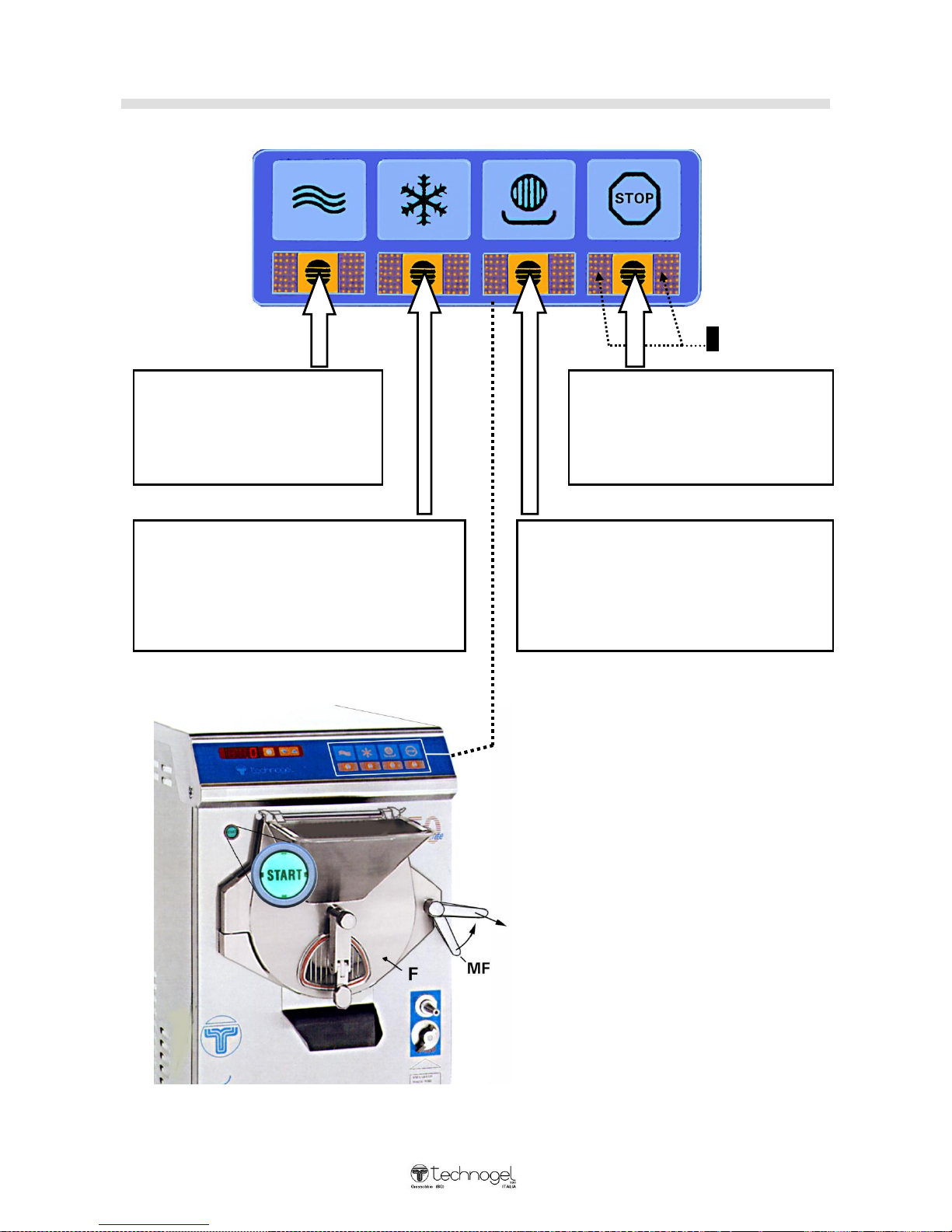
Control console functions – Control keyboard
1
WASHING key:
press this key to start the stirrer
motor at high speed.
It will stop automatically after 20
seconds.
STOP key:
when the console is connected to the
power supply this key automatically
lights up
Press this key to stop the machine at
any time.
ICE CREAM Key:
press to produce ice-cream.
Start-up of the stirrer motor at low speed and the
refrigeration compressor are separate. The stirrer
motor starts first and then after a few seconds the
refrigerator compressor is activated.
ICE CREAM OUTLET Key:
press this key to empty the machine of icecream rapidly.
In this position the stirrer motor rotates at high
speed.
In this position the refrigerator compressor will
not operate.
CAUTION:
If the (START) button is not connected
(light on), the keyboard and display
remain off.
If the flange handle (MF) is not properly
closed, the keyboard will not turn on
and will not accept commands.
If flange (F) is open, the keyboard will
remain off and will not accept
commands.
C:\Documents and Settings\mconti.TECHNOGEL-USA\My Documents\MACCHINE\ARTESAN\ART
MANUALS\Mantegel\Inglese\MG 2V Istruzioni Inglese 01-08.doc
28
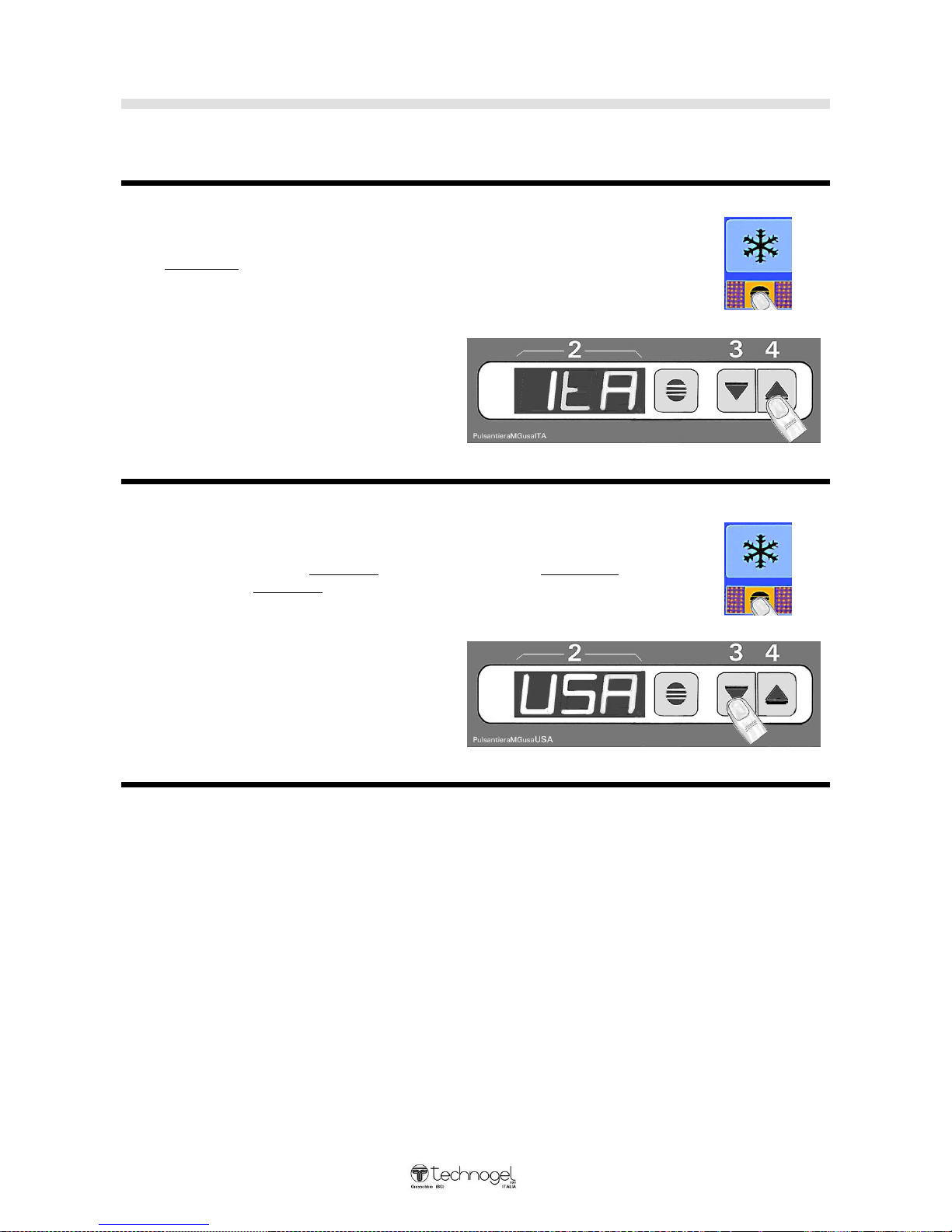
Console control functions
Instructions for changing Operational for ice-cream production
on the machine
“ ITA” Mode (Standard most commonly-used Mode) :
When you press the ICE-CREAM key the mixer turbine will rotate at
low speed.
How to insert “ ITA” M ode :
Press key 4 for four seconds and
display 2 will give “ I t A”.
Release key 4, and the operational
Mode is memorized.
ItA
“ USA” Mode :
When you press the ICE-CREAM key the mixer turbine will rotate for
about 10 seconds at low speed, for about 3 minutes at high speed
and again at low speed till the end of the cycle.
How to insert “ USA” Mode :
Press key 3 for four seconds and
display 2 will give “ U S A”.
Release key 3, and the operational
Mode is memorized.
USA
CAUTION:
For each Mode, ItA or USA, set the texture of the ice-cream you wish to produce as described on
page 20.
Before starting production, press the appropriate key (3) or (4) to find
which Mode has been set.
C:\Documents and Settings\mconti.TECHNOGEL-USA\My Documents\MACCHINE\ARTESAN\ART
MANUALS\Mantegel\Inglese\MG 2V Istruzioni Inglese 01-08.doc
29
FOR INITIAL START-UP, PRESS THE “ START” BUTTON AND WAIT FOR AT
LEAST 60 MINUTES BEFORE PRESSING ANY KEYS.
IF THE MACHINE IS DISCONNECTED FROM THE POWER SUPPLY FORONE OR
MORE DAYS, IT WILL BE NECESSARY TO PRESSS THE “ START” BUTTON AND
THEN WAIT FOR 30 MINUTES BEFORE PRESSING ANY KEY WHATSOEVER.
IF THE POWER SUPPLY IS NEVER DISCONNECTED FROM THE MACHINE
IT CAN BE STARTED WITHOUT HAVING TO WAIT FOR ANY PERIOD OF TIME.
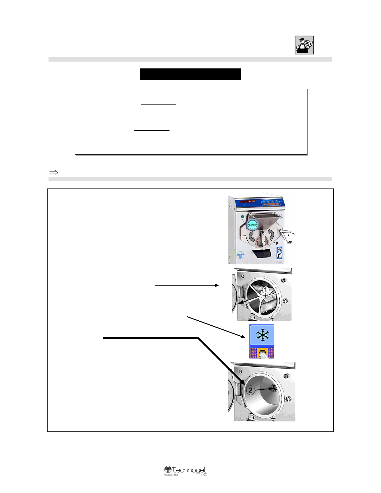
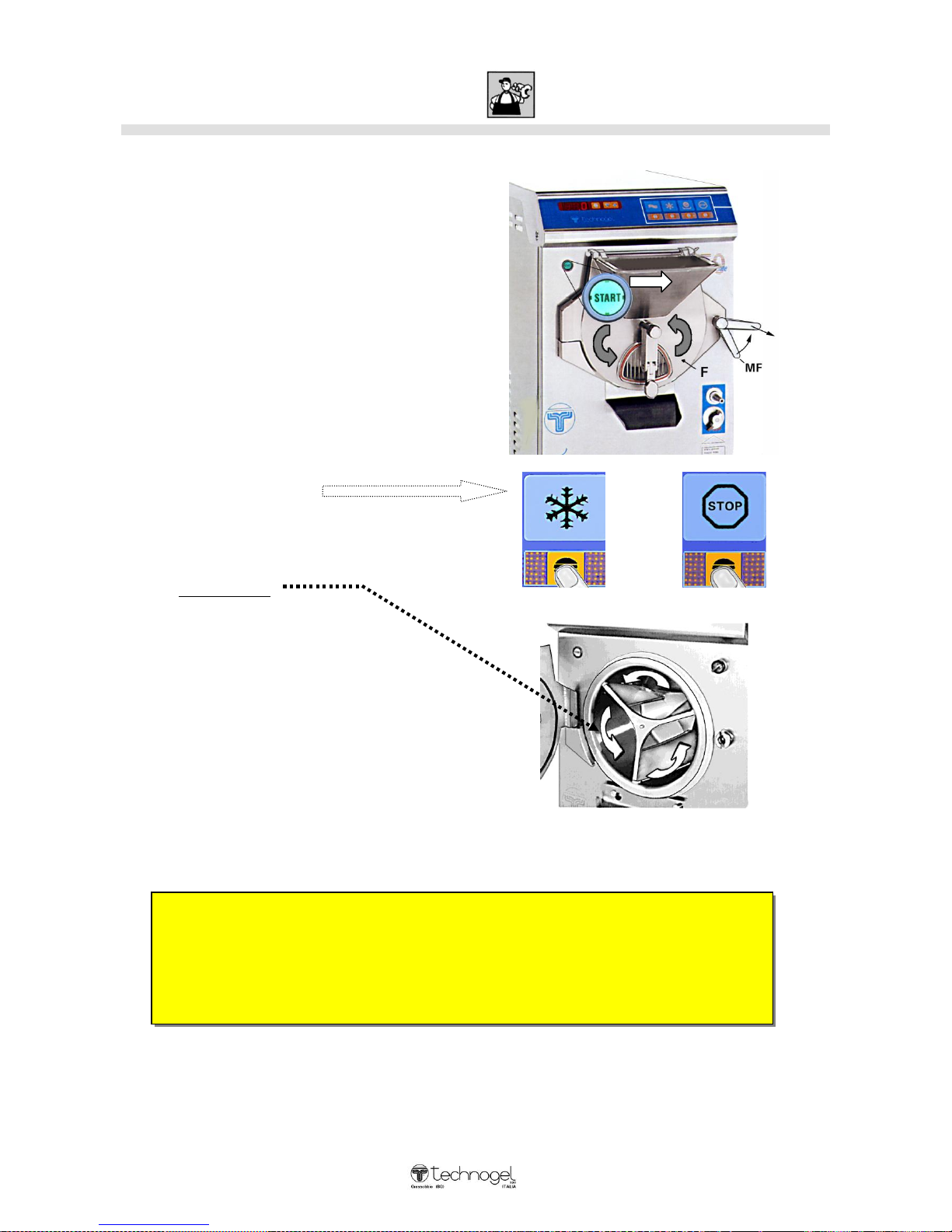
Machine start-up:
CAUTION IMPORTANT
Checking efficient operation of safety device on front door
1) Disconnect the power supply to the control
console by pressing the START button
(light off)
2) Open the front door (F) by rotating the
handle (MF) anticlockwise and then pull
towards the outside.
3) Extract the dasher (1) by grasping it by the
spokes and pulling outwards.
4) Reconnect the power supply by pressing
the START button (light on).
5) Press the ICE-CREAM key and check the
bottom of the freezing chamber. In the
centre you will see the triangular dasher
device (2).
IF THE TRIANGULAR DASHER DEVICE (2)
DOES NOT ROTATE, THIS MEANS THAT THE
SAFETY DEVICE IS ACTIVATED AND IN
OPERATION
6) Close the front door (F) once again and lock
with the handle (MF). The control console
will light up switching to STOP.
When carrying out periodic controls, if the
device is not operating, please call the
Technical Assistance Service immediately.
CAUTION:
The device is designed to operate only in emergencies when the front door (F) is opened before the
machine has been stopped using the STOP key.
C:\Documents and Settings\mconti.TECHNOGEL-USA\My Documents\MACCHINE\ARTESAN\ART
MANUALS\Mantegel\Inglese\MG 2V Istruzioni Inglese 01-08.doc
30
TECHNOGEL spa, CANNOT BE HELD RESPONSIBLE FOR ANY DAMAGE CAUSED BY
IMPROPER USE OF THE MACHINE OR BY INCORRECT INSTALLATION DUE TO HASTE
AND/OR NEGLIGENCE.
CHECKING THE SAFETY DEVICES AND ENSURING THEIR CORRECT OPERATION
MEANS THAT THE OPERATOR CAN BE SECURE IN THE KNOWLEDGE THAT NO RISK
IS INVOLVED IN HIS WORK.
Checking the direction of rotation
When the machine is empty:
Connect the console to the power supply
using the START switch.
Checking from the hopper of front door (F),
press the ICE-CREAM key and Immediately
after the STOP key
The dasher which mixes the ice-cream must
rotate anticlockwise;
if it fails to do so:
1 – Disconnect the power supply to the console
by pressing key (IG).
2 – Detach the machine cable from the power
supply and invert any two of the three
phases.
3 – Reconnect the power supply and try
again.
 Loading...