

TECHNOFASE RDM BK43-1A, RDM BK43-3A, RDM BK43-3B, RDM BK43-6B, RDM BK43-9A Technical Manual
Page 1
Technical Manual Page 1 of 17
www.technofase.com
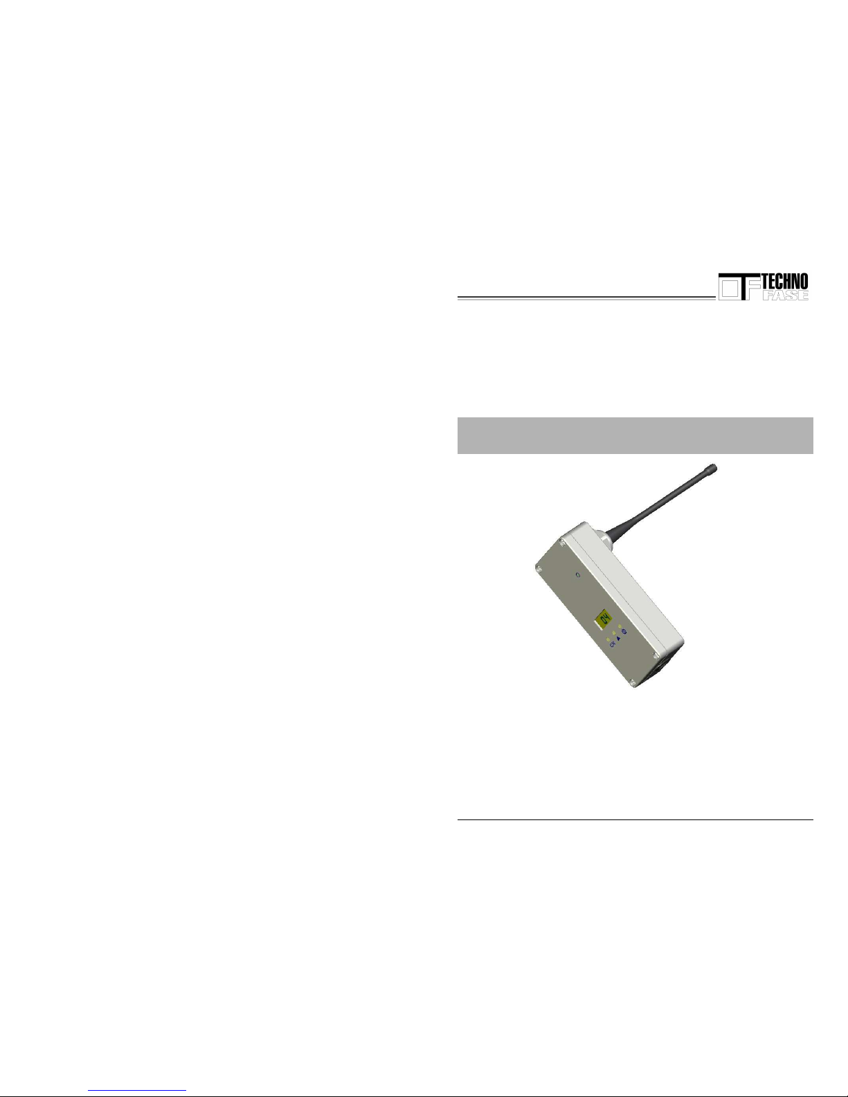
RDM BK43
Valid for versions RDM BK43 - 1A
RDM BK43 - 3A
RDM BK43 - 3B
RDM BK43 – 6B
RDM BK43 – 9A
Page 2
Technical Manual Page 2 of 17
www.technofase.com
GENERAL INDEX
Foreword.................................................................................... 4
1. Safety instructions for the user and safety measures
for the RDM BK43 system ....................................................... 5
Supplementary notes for RADIO interface appliances ...... 6
2. Introduction..........................................................................7
2.1 Environmental characteristics.......................................................................... 7
3. Compliance with the standard...........................................7
3.1 Reference Standard .............................................................................................. 8
3.2 CEPT 70-03 Recommendation ....................................................................... 9
3.3 Identification...................................................................................................... 9
4. Technical data.....................................................................10
4.1 Models available .............................................................................................. 10
4.2 Standard radio channels................................................................................. 11
4.3 Communication interfaces.............................................................................. 12
4.4 Power supply ...................................................................................................12
4.5 Connections...................................................................................................... 12
5. Assembly specifications....................................................13
5.1 External assembly .......................................................................................... 13
5.2 Assembly inside an electrical panel ............................................................. 13
6. Button functions.................................................................14
7. Labelling of the various models....................................... 15
7.1 RDM BK43-3A Label........................................................................................ 15
7.2 RDM BK43-3B Label ........................................................................................ 15
7.3 RDM BK43-6B Label ........................................................................................ 15
7.4 RDM BK43-9A Label........................................................................................ 15
8. Product guarantee .............................................................16
Page 3
Technical Manual Page 3 of 17
www.technofase.com
8.1 Terms of the guarantee.............................................................................. 16
9.1 Standard concerning disposal ...................................17
Manufacturer ..........................................................................................................17
Page 4
Technical Manual Page 4 of 17
www.technofase.com
Foreword
• This manual contains text, images and explanations for the correct
installation and use of the RDM BK43 transceiver. It should be read and
understood before the appliance is installed and used.
• This manual has been published subject to alteration. We reserve the right to
modify this manual without prior notice.
• As the system works by means of radio waves, transmission may, in certain
cases, be influenced by the environment and by the method of use. The
manufacturer is not liable for any damage to persons and/or appliances.
• Do not use the system near other appliances operating with radio waves as
this could cause malfunctioning.
IMPORTANT
• Do not remove or replace any parts of the system.
• Do not remove, alter or modify the identification plate on the back of the
system. It is forbidden to use the system without identification plates.
Hardware Manual
Revision: B.0
Date: 06/2007
Page 5
Technical Manual Page 5 of 17
www.technofase.com
1. Safety instructions for the user and safety measures
for the RDM BK43 system
This manual has been drawn up for use by trained and competent personnel.
The qualification of the personnel is defined in the European Directives on
machines, low voltage and EMV. All the electrical connections of RDM BK43
systems must be carried out by a technician who has specific training in local
and national electrical standards. Several symbols are used in this manual to
highlight certain information. The purpose of these symbols is to draw the
attention of personnel involved to warnings concerning safety and to safety
measures. Whenever a symbol appears, the relevant note should be read and
the information followed carefully.
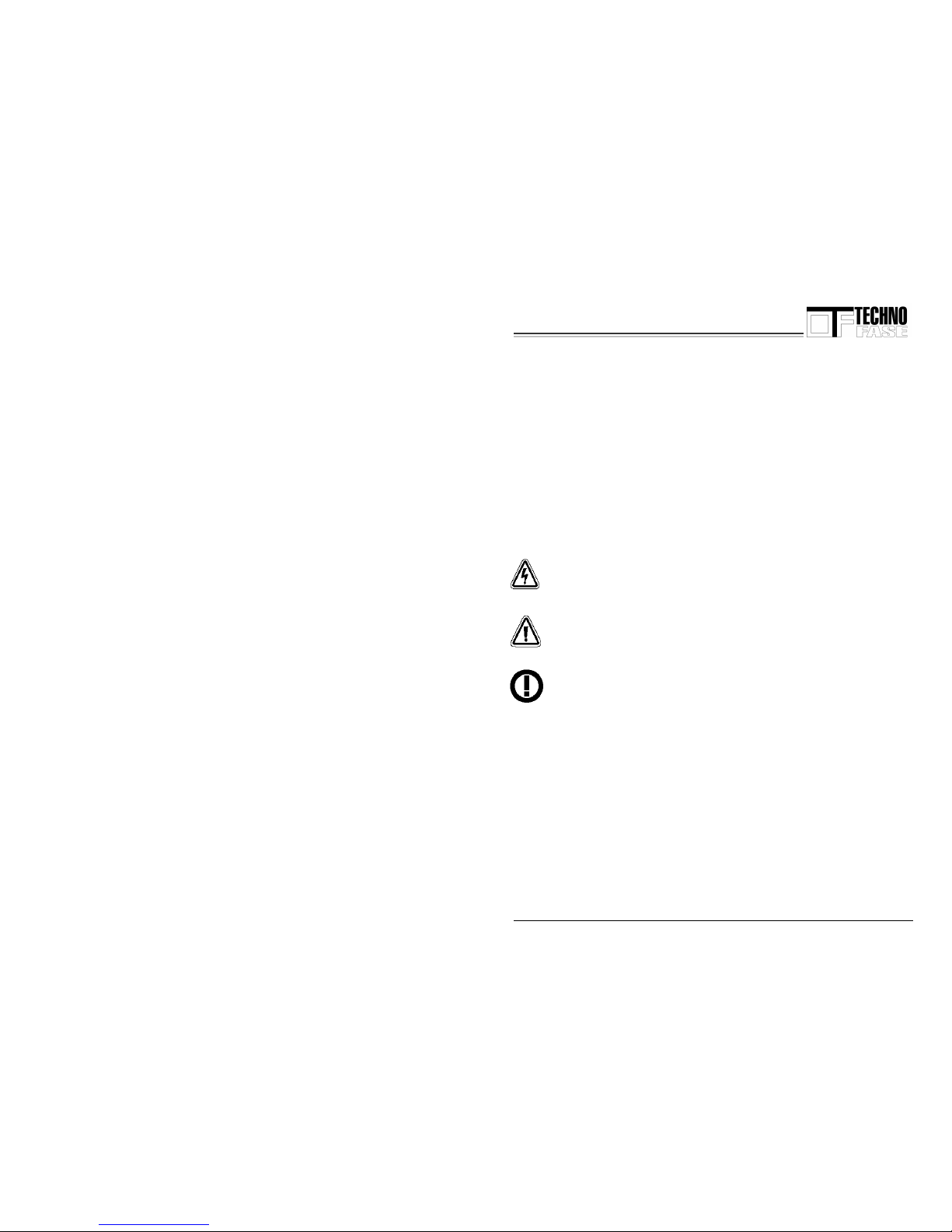
This symbol indicates an imminent danger causing damage to persons
or property.
This symbol indicates a danger that could cause damage to persons or
property.
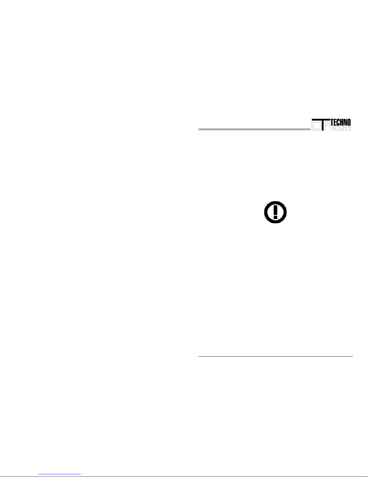
This symbol indicates the need to check the harmonization for the use
of radio frequency.
Page 6
Technical Manual Page 6 of 17
www.technofase.com
• TECHNOFASE cannot be held responsible for damage due to inappropriate
installation or operation of the appliances.
• Do not replace the electrical components or attempt to repair products of the
RDM BK43 series in any way.
• The products of the RDM BK43 series must be used in accordance with the
relevant local and national standards in force.
Supplementary notes for RADIO interface appliances
The products with radio interface have been designed to operate on UHF radio
frequencies (433 – 436MHz) that vary from one country to another. The user
must take care to check the standards in force in the country in which the
appliance is being used before putting it into use.
Contact the local Ofcom (Office of Communications) agency to obtain a licence
or further information concerning the limitations on the free, unrestricted use
(SRD) of the appliance.
Page 7
Technical Manual Page 7 of 17
www.technofase.com
2. Introduction
The RDM BK43 system has been developed for transmitting and receiving data
via radio.
The special features of the RDM BK43 system are the following:
• Considerable immunity to disturbances
• Compact size
• IP65 die-cast aluminium casing
• Easily accessible RS232 communication port
• Up to 16 programmable channels that can be set using the buttons
• Power supply ranging from 10 to 15V
• Built-in flexible antenna ¼
2.1 Environmental characteristics
• Operating temperature -20 / 50 °C
• Storage temperature -25 / 50 °C
• Relative humidity 5-85%, without condensation
• Vibration resistance
Page 8
Technical Manual Page 8 of 17
www.technofase.com
3. Compliance with the Standard
The system complies with the following harmonised standards:
• EN 61000-6-1 Immunity to disturbances
• EN 61000-6-3 Immunity to disturbances
• EN 50082-2 Conducted emissions
• EN 60950 Electrical safety
• EN 301-489-1 + EN 301-489-3 Radio appliances
• EN 300-220-1 + EN 300-220-3 ISM Band SRD
• EN 300-296-2
3.1 Reference Standard
The RDM BK43 transceiver complies with the following European standards:
EN 300 220, EN 301 489, EN 300 296.
Furthermore, the product has been tested according to standard EN 60950.
Page 9
Technical Manual Page 9 of 17
www.technofase.com
3.2 CEPT 70-03 Recommendation
The RDM BK43 product operates on a harmonised frequency band and
therefore, to comply with the standard in force, it must be used, on the time
scale, for 10% max. of an hourly duty cycle (corresponding to 6 minutes of
use per hour).
NOTE: In view of the construction system, the user is responsible for
compliance with this parameter.
3.3 Identification
The product is identified by the product identification number and a sevendigit number (representing the series number and year of manufacture) on the
casing.
Page 10
Technical Manual Page 10 of 17
www.technofase.com
4. Technical data
Make TECHNOFASE
Model BK43-XX
Channels Selectable, up to 24
Max. RF power 500mW ERP
Frequency stability +/- 1 KHz
Power supply 10-15V DC
Operating temperature -20 / 50 °C
Sizes excluding
antenna
150 x 64 x 36 mm
4.1 Models available
The models vary according to the frequency band and the antenna power
RDM BK43 Mod. 3A 433.175 - 434.675MHz 500mW ERP
1
RDM BK43 Mod. 3C 433.050 - 439.420MHz 500mW ERP
1
RDM BK43 Mod. 3B 433.050 - 434.790MHz 10mW ERP
2
RDM BK43 Mod. 6B 436.000 - 436.100MHz 500mW ERP
3
RDM BK43 Mod. 9A 439.700 - 439.975MHz 500mW ERP
4
RDM BK43 Mod. 1A 441.025 - 441.775MHz 500mW ERP
5
1)
This model can only be used in Austria and Switzerland after payment of the local licence fee.
2)
This model can only be used in countries in which this power limit is applied. Check with the
competent Office of Communications for possible use.
3)
This model can only be used in Italy according to the frequency assignment plan, point 101A,
after filing a general authorisation application as set out in Presidential Decree no. 447 of 5
October 2001, Art. 5, Para. 1, Point 2, and after payment of the relevant fee. Contact the local
department of the Office of Communications for further information concerning its use.
4)
This model can only be used in Sweden in compliance with the country’s regulations.
5)
This model can only be used in Norway in compliance with the country’s regulations.
Page 11
Technical Manual Page 11 of 17
www.technofase.com
4.2 Standard radio channels
BK43-3A
25KHz
BK43-3C
25KHz
BK43-6B
12.5KHz
BK43-9A
25KHz
BK43-1A
12.5KHz
CH 1
433.825 433.825 436.00625 439.700 441.0250
CH 2
433.875 433.875 436.01875 439.725 441.0750
CH 3
433.925 433.925 436.03125 439.750 441.1250
CH 4
433.975 433.975 436.04375 439.775 441.1750
CH 5
434.025 434.025 436.05625 439.800 441.2250
CH 6
434.075 434.075 436.06875 439.825 441.2750
CH 7
434.125 434.125 436.08125 439.850 441.3250
CH 8
434.175 434.175 436.09375 439.875 441.3750
CH 9
433.825
123
433.825
123
436.00625
123
439.900 441.4250
CH 10
433.875
123
433.875
123
436.01875
123
439.925 441.4750
CH 11
433.925
123
433.925
123
436.03125
123
439.950 441.5250
CH 12
433.975
123
433.975
123
436.04375
123
439.975 441.5750
CH 13
434.025
123
434.025
123
436.05625
123
441.6250
CH 14
434.075
123
434.075
123
436.06875
123
441.6750
CH 15
434.125
123
434.125
123
436.08125
123
441.7250
CH 16
434.175
123
434.175
123
436.09375
123
441.7750
CH 17
433.900 433.900 436.00625
CH 18
433.950 433.950 436.01875
CH 19
434.100 434.100 436.03125
CH 20
434.150 434.150 436.04375
CH 21
434.200 434.200 436.05625
CH 22
434.400 439.390 436.06875
CH 23
439.410 436.08125
CH 24
439.430 436.09375
Page 12
Technical Manual Page 12 of 17
www.technofase.com
4.3 Communication interfaces
RS232 RS232 standard interface
Mini DIN 6 F type connection
4.4 Power supply
The RDM BK43 transceiver must be run on a very low safety voltage
supply protected against short circuits.
Supply voltage: 10-15V
Maximum absorption in Tx: 400 mA
Protection against short circuits: Polyswitch
Type: Resettable RXE040
4.5 Connections
For external connections, a screened cable with a MINIDIN 6 type
connector has been provided both for data and for the power supply.
All electrical connections are designed for lengths up to a max. of 3m.
Page 13
Technical Manual Page 13 of 17
www.technofase.com
5. Assembly specifications
5.1 External assembly
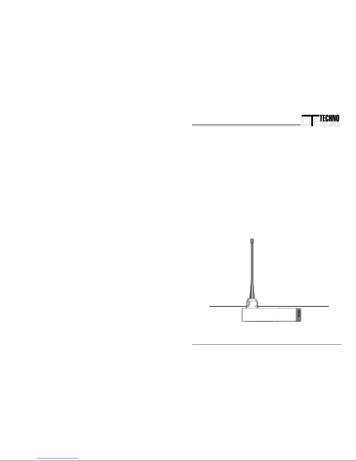
External assembly can be carried out using a support plate with a 24
mm hole in the centre. This plate must then be fixed to a suitable
means of support.
5.2 Assembly inside an electrical panel
For assembly inside an electrical panel, a hole 24 mm in diameter must
be drilled to allow the antenna to transmit and receive outside. The
earthing surface must be at least 20cm x 20cm in size.
Page 14
Technical Manual Page 14 of 17
www.technofase.com
6. Button functions
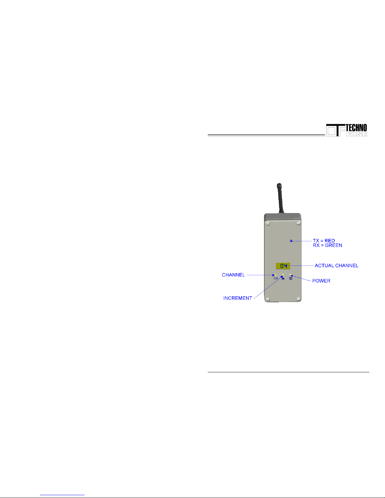
Three rubber buttons are located in the lower part to set the channel and to
switch the appliance on/off.
The display shows the number of the channel currently set. To change
channels, press the CHANNEL button until the number shown on the display
starts flashing (ACTUAL CHANNEL): then press the INCREMENT button to
increase the channel number. To lower the number continue pressing the
button until the last channel (24) is reached and the system starts again from
1. After setting the channel, press the CHANNEL button again until the flashing
stops. The TX/RX LED indicates reception when green and transmission when
red.
Page 15
Technical Manual Page 15 of 17
www.technofase.com
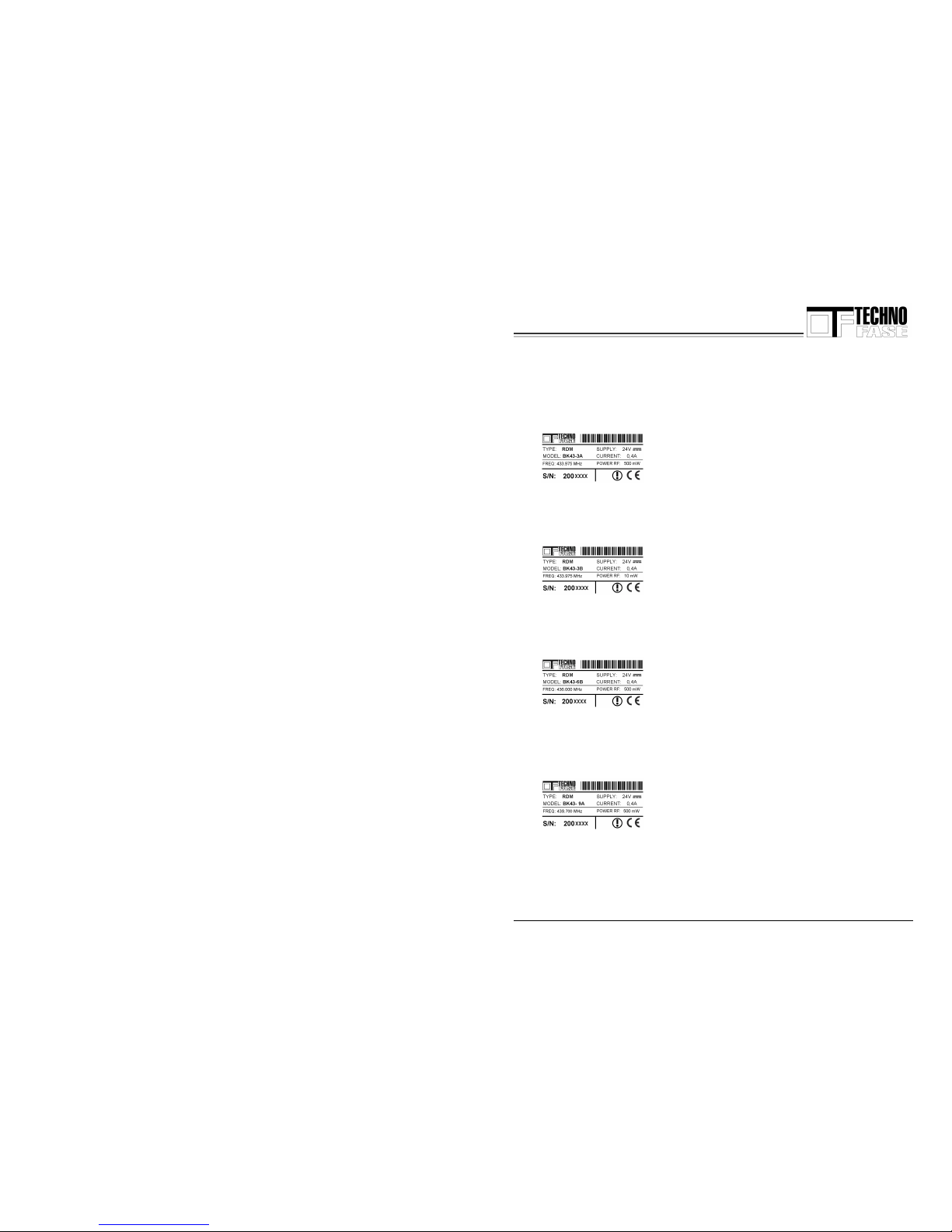
7. Labelling of the various models
7.1 RDM BK43-3A label
7.2 RDM BK43-3B label
7.3 RDM BK43-6B label
7.4 RDM BK43-9A label
Page 16
Technical Manual Page 16 of 17
www.technofase.com
8. Product guarantee
8.1 Terms of the guarantee
8.2.1 GUARANTEE AND CONDITIONS
Technofase products are covered by a 2 (TWO) YEAR guarantee from the date of
purchase with the exception of the batteries which are covered by a 6 (SIX) MONTH
guarantee. During this period Technofase undertakes, at its sole discretion, to repair or
replace faulty components with similar or equivalent products or to refund the
Customer for the amount paid for the component in the case of faulty material or
manufacturing defects. If the label with the series number of a product has been
cancelled, tampered with, or partially or completely covered, Technofase reserves the
right not to consider such a product under guarantee. The guarantee covers
manufacturing faults in the components at the time of purchase and the labour
necessary to repair them.
The guarantee is null and void in the event of: improper use of the product, negligence,
intentional damage or any problem due to incorrect installation after purchase. The
guarantee is of the “on-centre” type, i.e. the customer is only liable for paying the cost
of dispatching the faulty product to the repair shop.
8.2.2 DURATION OF THE GUARANTEE FOLLOWING SERVICES UNDER THE
GUARANTEE
Any service carried out under the guarantee will not prolong the duration of the
guarantee.
8.2.3 RESPONSIBILITY TOWARDS THIRD PARTIES
The buyer will not hold Technofase responsible with regard to any controversy that
may arise with the final user as the buyer undertakes to check in advance the
appropriateness of the system configuration and of every single component he has
purchased. It is expressly understood that Technofase is responsible only towards the
first buyer and exclusively within the terms provided for by the guarantee clause.
Page 17
Technical Manual Page 17 of 17
www.technofase.com
9.1 Standard concerning disposal
EC-Directive 2002/96 Waste electrical and electronic appliances –
RAEE.
This product complies with EU Directive 2002/96/EC.
The symbol of the crossed litter bin appearing on the appliance
indicates that at the end of its useful life the product must be
disposed of separately from household waste. The user is responsible
for taking the appliance to a suitable collection point at the end of its
life. Separate waste collection and subsequent recycling, processing and the ecofriendly disposal of exhausted appliances contribute towards preventing negative
effects on the environment and on health and help to recycle the materials of which the
product is made. Contact the local waste disposal service or the shop in which the
product was purchased for more detailed information concerning the collection systems
available.
Manufacturer
RDM BK43 is made by:
TECHNOFASE
Via GALVANI 23
39100 BOLZANO
Tel 0471500450
Fax 0471513944
THE TERMS AND CONDITIONS IN THIS DOCUMENT MAY BE CHANGE D WITHOUT PRIOR NOTICE.
 Loading...