

Page 1
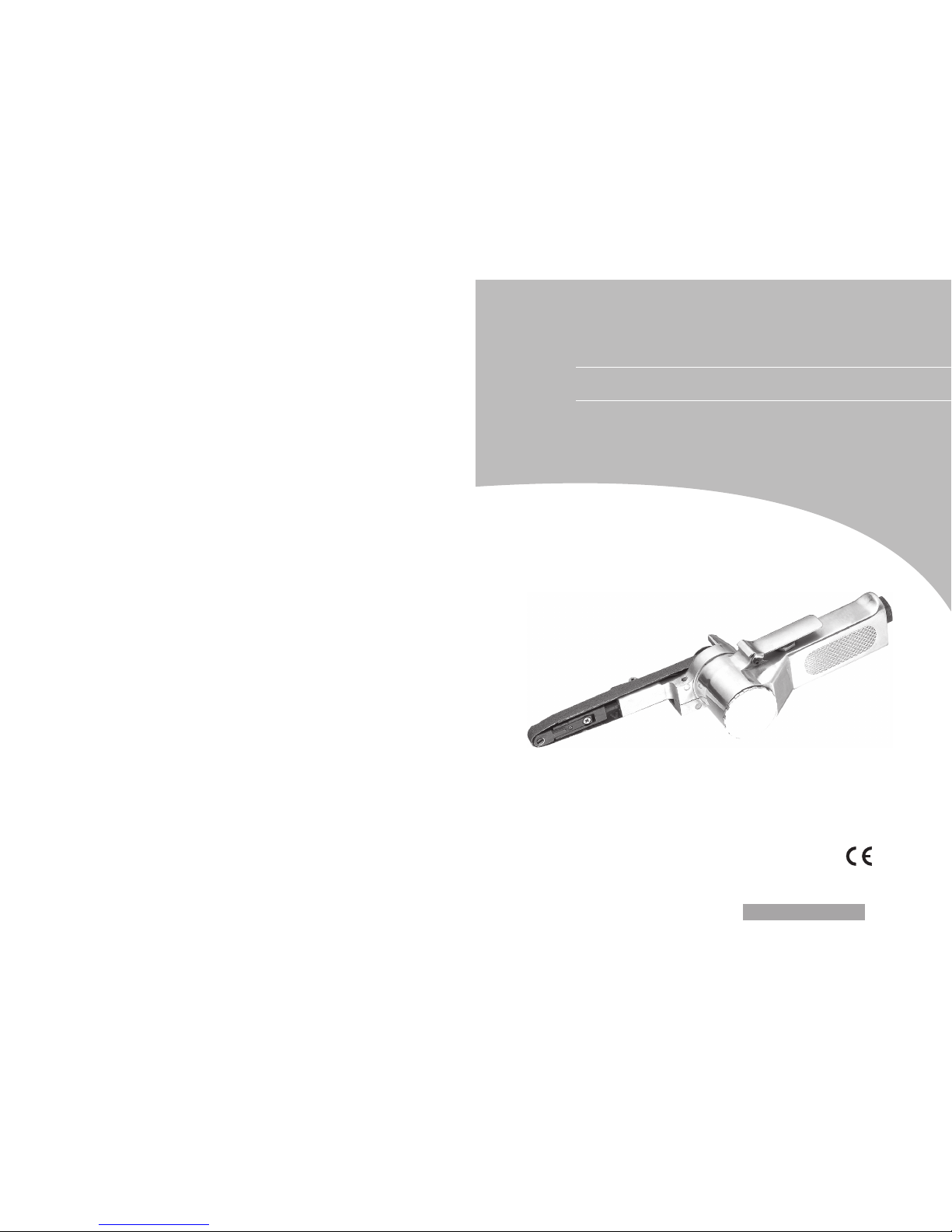
10mm Air Belt Sander (Model AT-480)
INSTRUCTION MANUAL
Thanks for your purchasing our air tools
and please read this Instruction Manual carefully
and thoroughly before operating the tool to do your best jobs.
Revision: 01 (2004)
Page 2
A. Features & Functions
* The smallest handy sander with 10mm wide belt. Lever throttle for featuring control.
* Easy belt replacement. Suitable for jobs in narrow spaces and recessed corners.
* Helps you to do fine sanding jobs like wood-working, furniture-polishing, plastic,
aluminum & metal-polishing and even small spot sanding jobs like trims, curves,
and other difficult-to-reach spots for common sanding machines.
* 3 different grit sanding belts (60, 80, 120 grit) included for different purpose and
function.
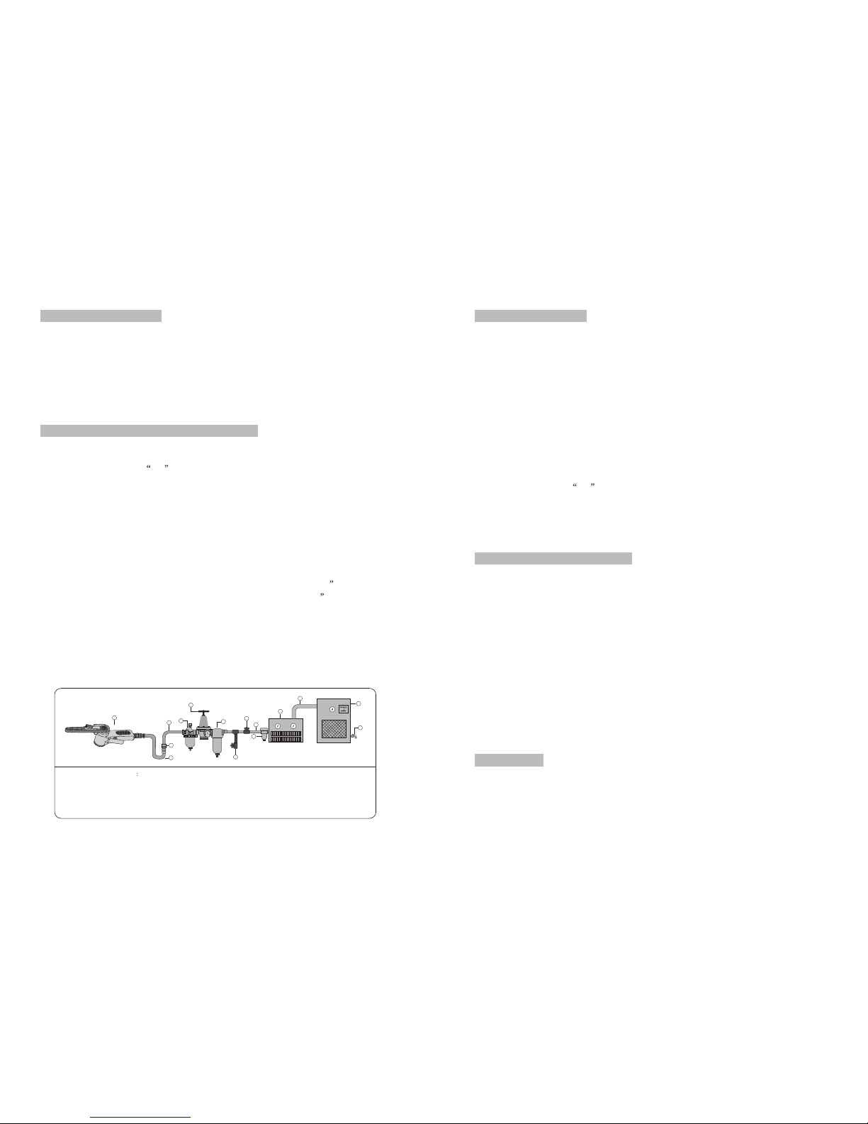
B. Air Supply (please refer to the diagram below)
1. Make sure that the air compressor being used for the air tool operation supplies the
correct output (CFM).
2. Turn the throttle in the off position when connecting the tool to the air supply.
3. Use normal 90psi (or ranging from 6.0 to 8.0kg.) air pressure while running the tool.
High pressure and unclean air will shorten the tool’s life due to faster wear and also
may create a hazardous situation.
4. Drain the air tank daily. Water in the air line may enter the tool and damage the tool
mechanism at the operation.
5. Clean the air inlet filter cartridge weekly. The recommended hook-up procedure can
be viewed in the diagram below.
6. Line pressure should be increased accordingly to make up for extra long air hoses
(usually over 8 meters). The minimum hose diameter should be 1/4 I.D. and the
fittings should have the same inside dimensions. But usually a 3/8 I.D. air hose is
recommended for air supply to get the best function of air tool operation.
7. Use proper hoses and fittings. We do not suggest connecting quick change couplings
directly to the tool since they may cause failure due to vibration. Instead, add a
leader hose and connect coupling between air supply and hose whip.
8. Keep hoses away from the heat, oil and sharp edges. Check hoses for wear before
individual use. Make certain that all connections are in security.
C. Safety Instructions
1. Approved eye protector must be worn at all times. Be sure to use a dust mask since
the tool operation may creates dust which is harmful to health. If necessary, ear
protector and gloves should be used.
2. Always keep good balance of body and footing. Secure work with clamps or vice so
both hands can be free to operate the tool.
3. Be sure all clothing is tight to prevent entanglement with running tools. Remove
your jewelry and watch for safety purpose.
4. Be sure that working area is clear of foreign objects and that no people are within
immediate access of tool operation scope. The working place shall be well
ventilated.
5. Disconnect the air hose before changing or adjusting any inserted tools/accessories.
6. Be sure the tool is in off position before connecting it to the air hose.
7. Disconnect the tool when it is not in use. Release the on-off device in case of energy
supply failure.
8. Never carry tool by hose.
D. Maintenance And Lubrication
1. If you are not using an air line oiler, lubricate the air motor by using an oil pot or an
oil injector through the air inlet and then run the tool. Several drops of SAE #10
lubricant or sewing machine lubricant is acceptable for this purpose. Do not use
detergent oil.
2. Before connecting the hose for operation, apply 4 or 5 drops of #10 spindle oil at the
air inlet. Avoid the misuse of thicker oil which may lead to the reduced performance
or malfunction.
3. Oiling is necessary within 3 or 4 hours of operation.
4. After operation, take off the air hose and pour 4 or 5 drops of #60 spindle oil into the
air inlet, then connect the hose again to run the tool for a few seconds, which can
prolong the tool life.
5. Clean air inlet filter cartridge on the air line weekly.
E. Warnings
1. Never use the tool in potentially explosive atmospheres.
2. Keep your body in well balanced position and always wear gloves to reduce the risk
of crushing caused by torque between a reaction bar and work-piece.
6. Shut Off Valve
7. Whip Hose
8. Coupler Body And Connector
9. Drain Daily
10. 1/2” Or Larger Pipe And Fitting
1. Air Tool
2. Air Hose 3/8”(I.D.)
3. Oiler
4. Pressure Regulator
5. Filter
11. Air Dryer
12. 1” Or Larger Pipe And Fitting
13. Air Compressor
14. Auto Drain
15. Drain Daily
AIR SYSTEM LAYOUT
6
9
14
8
7
1
12
10
5
4
3
2
11
13
15
Page 3

3. Unexpected tool movement due to reaction forces or breakage of inserted tool or
reaction bar may cause injuries.
4. Prevent long hair or loose clothing from drawing in while operating the tool. You
may get the risk of being injured if the handkerchief, necktie etc. are not kept away
from the running tool.
5. The noise emission (sound pressure level) at the workplace may exceed the normal
standard ---usually 85dB(A). In this case, a quality ear protector should be used.
6. Unexpected direction of inserted tool movement could case a hazardous situation.
7. Slip / Trip / Fall is a major cause of serious injury or even death. Be aware of excess
hose left on your walking way or on the working surface and be aware of the
whipping air hose too.
8. Excessive high air pressure and too much free rotation may speed up the wear of the
tool and may cause dangerous situation.
9. Continuous operation and bad working condition will injure hands. Once hand
numbs or aches , operator shall stop the tool for a while for relaxing and re-start the
work after recovery. Operator shall immediately see a doctor if such a serious
symptom occurs.
10. Never change the inner construction and design, which may cause a danger in
operation.
F. General Trouble Shooting
* Troubles:
- Tool does not run at a normal speed or at a variable speed
- The motor blocks
- Automotive start when connected to compressed air
- Torque reduces
- Abnormal vibrating -Easy hot rising at the housing
* Causes:
- Air supply is not enough (air pressure not in a required standard)
- Speed controller/switch breaks down
- Rotor blades break or wear out
- Dust gets into the motor
- Throttle lever or starting trigger malfunctions
- Air leakage at the inlet or somewhere else
- Bearing(s) damages
- Correspondent O-ring(s) wears out or out of position
- Lack of lubricating
* Troubles Shooting:
- Check the air hose to see whether it is blocked or twisted for less air supply.
- Check the air compressor to gain the correct air pressure required.
- Replace rotor blades
- Disassemble the tool and clean the inner structure under proper instructions
- Check and fix the throttle lever or starting trigger for accurate operation
- Check the air leakage and fix it under proper instruction
- Replace new bearing(s)
- Replace the damaged O-ring(s) or put it back in correct position
- Oil / Lubricate the tool consistently until it gains the right speed and torque
* Note:
For any other special troubles which cannot be settled down by the operator, please
contact the selling agent from whom you purchase the tool.
G. Storage
Avoid to store the tool in a location subject to high humidity, which may result in rusty
mechanism inside the tool. Before storing, oil the tool at the air inlet with proper
spindle oil and run it for a few seconds.
H. Disposal
When the tool is seriously damaged or out of life, leave it in a resource recycling can.
Never drop it into fire.
I. Ordering Spare Parts
1. Contact the sale agent from whom you purchase the tool for spare parts ordering for
any necessary replacement for continuous use of tool and extending the tool life.
2. In ordering spare parts and components, give each spare part number and order
quantity.
Thank you.
Page 4
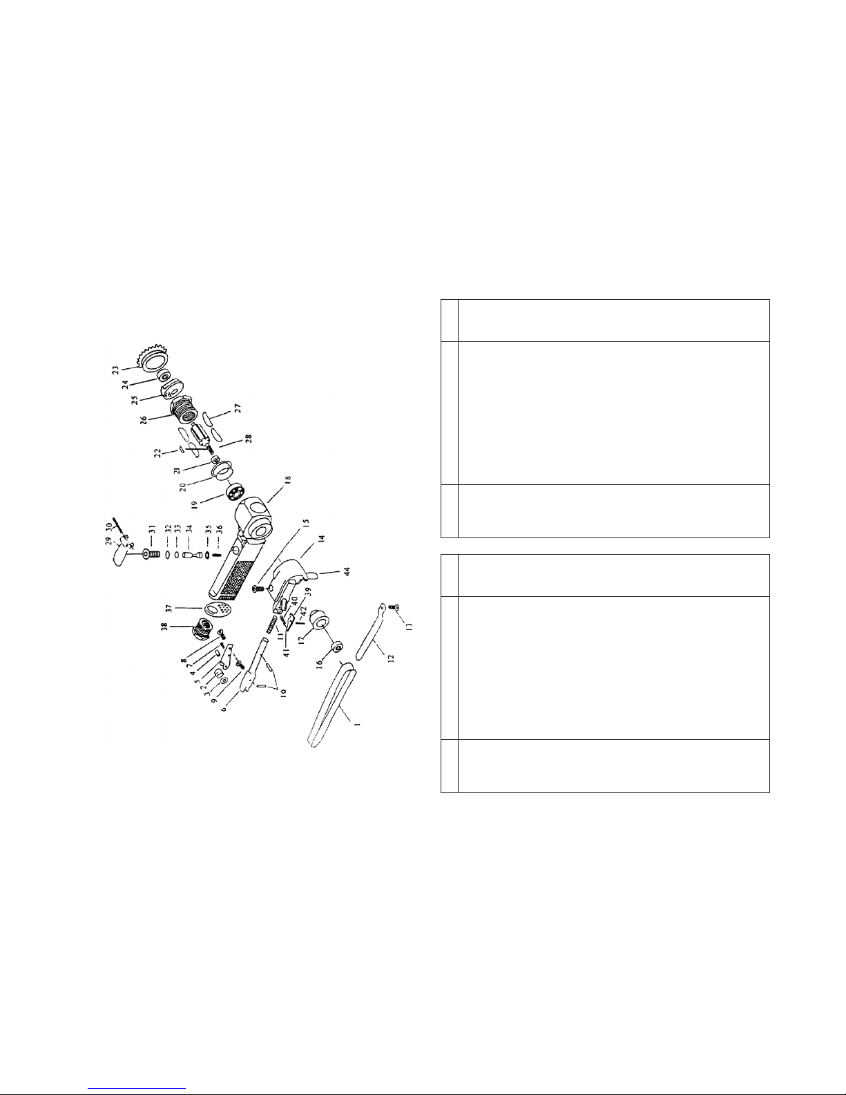
TECHNICAL DATA:
* Free Speed: 16,000 RPM * Sanding Belt: 2/5" x13" (10 x 330 mm) * Air Inlet (PT): 1/4"
* Air Hose(ID): 3/8" * Avg.Air Consumption: 6 SCFM * Working Pressure: 90 PSI (6.3 BAR)
10mm Air Belt Sander (Model: AT-480)
SPARE PARTS LIST
Part No.
Description
Part No.
Description
21
22
23
24
25
26
27
28
29
30
31
32
33
34
35
36
37
38
39
40
41
42
Grinding Belt
Grinding Belt
Grinding Belt
Idle Pulley
Washer
Idle Pulley Screw
Bracket 10
Tension Bar 10
Hexagon Socket Headless
Set Screw 3x10
Cross-Recessed Flat Head
Mashine Screw 3x8
Spring 1.0x7.2x6.5
Spring Pin 3x10
Spring 1.07x4.0x35.5
Shoe 10
Cross-Recessed Flat Head
Mashine Screw 4x8
Guard Sud Assy A
Hexagon Socket Head
Bolt 5*15
Hexagon Pulley
Drive Pulley
Housing
Ball Bearing 628zz
End Plate B
Spacer 8x11x3
Sunk Key 3x3x1
Cap
Ball Bearing 607zz
End Plate A
Cylinder
Blade Assy (4pc/set)
Rotor
Throttle Lever
Lever Pin
Valve Body
O-ring (P9)
O-ring (P5)
Valve Stem
O-ring (3.6x2.4)
Valve Spring
Defrector
Air Inlet
Tension Bar
Spring
Lever Pin (m2x6)
Lever Pin (m2.5x10)
1
1A
1B
23456
7
8
9
10
11
12
13
14
15
16
17
18
19
20
Qty. Qty.
1
1set
1121111
1
12111
1
1
11111
1115111set
111121111111111
 Loading...