


VHF/FM
DIGITAL
AIRBORNE TRANSCEIVER
MODEL TDFM-136
Installation and
Operating Instructions
Til Document No.
99RE255
Rev. n/c
Issue n/c
DECEMBER 1999
Technisonic Industries Limited

250 Watline Avenue, Mississauga, Ontario L4Z 1P4 Tel:(905)890-2113 Fax:(905)890-5338
3840 East Robinson Road, Suite 214, Amherst, New York 14228 Tel:(716)691-0669
CAUTION
This unit contains static sensitive devices. Wear a grounded wrist strap and/or conductive gloves
when handling printed circuit boards.
This device complies with Part 15 of the FCC Rules. Operation is subject to the following two
conditions : (1) this device may not cause harmful interference and (2) this device must accept any
interference received, including interference that may cause undesired operation.
NOTE: This equipment has been tested and found to comply with the limits fora Class B digital device,
pursuant to Part 15 of the FCC Rules. These limits are designed to provide reasonable protection
against harmful interference in a residential installation. This equipment generates, uses, and can
radiate radio frequency energy and, if not installed and used in accordance with the instruction
manual, may cause harmful interference to radio communications. However, there is no guarantee
that interference will not occur in a particular installation. If this equipment does cause harmful
interference to radio or television reception, which can be determined by turning the equipment of f
and on, the user is encouraged to try to correct the interference by one or more of the following
measures:
S Reorient or relocate the receiving antenna
S Increase the separation between the equipment and receiver
S Connect the equipment into an outlet or circuit different from that to which the receiver is
connected.
S Consult the dealer or an experienced radio/TV technician for help.
WARRANTY INFORMATION
The Model TDFM-136, VHF/FM Digital Transceiver is under warranty for one year from date of
purchase. Failed units caused by defective parts, or workmanship should be returned to:
Technisonic Industries Limited Technisonic Industries Limited
250 Watline Avenue 3840 E. Robinson Road, Suite 214
Mississauga, Amherst,
Ontario L4Z 1P4 New York 14228
Tel: (905) 890-2113 Fax: (905) 890-5338 Tel: (716) 691-0669

A Page
Summary of DO-160C Environmental Testing for Technisonic Model TDFM-136, VHF Digital
Transceiver
Conditions Section Description of Conducted Tests
Temperature and Altitude 4.0 Equipment tested to categories B2 and
D1.
Vibration 8.0 Equipment is tested without shock
mounts to categories B, M and N.
Magnetic Effect 15.0 Equipment is class Z.
Power Input 16.0 Equipment tested to category B.
Voltage Spike 17.0 Equipment tested to category B.
RF Emission 21.0 Equipment tested to category Z.

1.1 INTRODUCTION
This publication provides operating and installation information on the TDFM-136, Digital
Transceiver manufactured by Technisonic Industries Limited. The TDFM-136 is Project 25
(P25), Phase 1 compliant. The unit offers digital or conventional analog FM communications
over an extended frequency range with selectable channel spacing and is intended for use (in
the U.S.) only by government agencies or contractors thereto, who have obtained licensing
for operation in the 136-150 MHz portion of the band. If the TDFM-136 transceiver is used
in CANADA, operation is restricted to the following sub bands: 138-144, 148-148.99,
149.005-150.005 and 150.05-174 MHz. Furthermore the frequency agile transceiver is
restricted to airborne use must not be operated as a base station in Canada.
1.2 DESCRIPTION
The TDFM-136, Transceiver is a frequency agile, fully synthesized airborne transceiver
capable of operating in the 136.000 MHz to 174.000 MHz frequency range in 2.5 kHz
increment s with either 25 kHz analog, 12.5 kHz analog channel spacing and P25, 12.5 kHz
digital modulation on a channel by channel basis. The Transceiver can operate without
restriction on any split frequency pair in the band and also incorporates a two channel
synthesized guard receiver.
B page
SECTION 1
GENERAL DESCRIPTION
The TDFM-136 Transceiver provides 150 operator accessible memory positions, each of which
is capable of storing a transmit frequency, receive frequency, transmit frequency CTCSS tone
or DPL code, receive frequency CTCSS tone or DPL code, an alphanumeric identifier for each
channel and in the TDFM-136, wideband (25 kHz analog) or narrowband (12.5 kHz analog)
channel spacing assignment. The P25 mode (12.5 kHz digital) channels include both NAC and
Talk Group capability.
Operating frequency and other related data are presented on a 48 character, two line LED
matrix display. Data entry and function control are performed via a 12 button keypad. Preset
channels may also be scrolled and scanned through keypad function activation.
1.3 PURPOSE OF EQUIPMENT
The TDFM-136, Digital VHF/FM Transceiver is designed to provide secondary airborne
communications to facilitate operations which are typically performed in a low altitude
environment. The transmitter section of this unit has a minimum of 8 watts and does not
exceed 10 watts output power, which may be reduced by a front panel switch to 1 watt, in
order to reduce interference to land based systems.
1.4 MODEL VARIATION
There are four variations of the Model TDFM-136 Transceiver. All units offer identical features
and performance except for the following differences:
TDFM-136, P/N 981087-1 GREEN display and 28 Volt back lighting.
TDFM-136, P/N 981087-1 (5V) GREEN display and 5 Volt back lighting.
TDFM-136, P/N 981087-2 RED display and 28 Volt back ligting.
1-1

TDFM-136, P/N 981087-2 (5V) RED display and 5 Volt back lighting.
Both P/N's 981087-1 and 981087-2 are always provided with 28 Volt back lighting unless a
specific request is made for 5 Volt AC operation.
1.5 TECHNICAL CHARACTERISTICS
Specification Characteristic
GENERAL
Model Designation: TDFM-136
Frequency Range: 136.000 to 174.000 MHz
Operating Modes: P25 CAI and conventional analog
Channel Spacing: 25 or 12.5 kHz
Physical Dimensions (including heatsink): Approx. 8.0" X 3.0" X 5.75"
Weight: Approx. 3.5 Lbs (1.6 Kg)
12.5/25 kHz conventional analog
12 KBPS FSK, 9.6 KBPS C4FM
Mounting: Panel Mount via Dzus fastners
Operating Temperature Range: -45EC to +70EC
Power Requirement:
Voltage: 28.0 Vdc, ± 15%
Current: Receive - 0.7 A Max.
1 Watt Transmit - 1.3 A Max.
8-10 Watt Transmit - 2.0 A Max.
Frequency Selection: 150 memories programmed with:
a) Tx Frequency/Rx Frequency
b) Tx/Rx CTCSS tone or DPL code
c) 9 character alpha numeric title
Guard Receiver: 2 channels programmed with:
a) Tx Frequency/Rx Frequency
b) Tx CTCSS tone or DPL code
c) 9 character alpha numeric title
CTCSS squelch/encoder: All CTCSS tones available
DPL digital squelch/encoder: All standard DPL codes
DTMF encoder: All standard DTMF tones
Audio Output: 0.5 Watts into 600 ohms
Speaker Output: 2.5 Watts min. into 4 ohms
Back Lighting: 28 Volts (standard) or
5 Volts (specify)
1-2

Display Colour: Green (standard) or
DPL is a trademark of Motorola Corporation
1.5 TECHNICAL CHARACTERISTICS (continued)
MAIN RECEIVER
Sensitivity at 12 dB SINAD -116dBm
Adjacent Channel Selectivity -60dB (25 or 12.5 KHz)
Spurious Attenuation -70 dB
Third Order Intermodulation -70 dB
Image Attenuation -80 dB
FM Acceptance ± 6 KHz
Red (specify)
NVG Optional
Hum and Noise Better than 45dB
Audio Distortion less than 5%
Antenna Conducted Emission less than -57dBm
GUARD RECEIVER
All specifications identical to main receiver.
TRANSMITTER
RF Power Output Lo -100mW to 1W (internal adjustment)
or hi-power; 10 watts.
Output Impedance 50 ohms
Maximum Deviation ±5 KHz (25 KHz mode)
(In narrowband mode) ±2.5 KHz (12.5KHz mode)
Spurious Attenuation -90 dB below carrier level
Frequency Stability ± 2.5 ppm
Microphone Circuit Carbon or equivalent
Sidetone Output 0.5W (max) into 600S
Harmonic Attenuation -65 dB below carrier level
FM Hum And Noise -40 dB
1-3

Audio Input 50 mV at 2.5 KHz into
200 S input circuit for
±3.5KHz deviation, adjst.
Audio Distortion Less than 5%
SECTION 2
OPERATING INSTRUCTIONS
2.1 OPERATING FEATURES
The Technisonic TDFM-136 airborne FM transceiver is visually similar to the industry standard TFM138, a two line by 24 character display is centered at the top of the unit, just below the display are
six user controls on the left and a 12 key keypad on the right (refer to Figure 2-1). The TDFM-136
support the following features:
1. 150 memory positions which can each be programmed with a transmit and receive
frequency with 25 or 12.5 kHz analog channel spacing, Tx/Rx CTCSS tones or DP L
codes and a 9-character alphanumeric title. Or the memory positions can be
programmed to P25 Digital mode (12.5 kHz) with or without a P25 Talkgroup.
2. 2 guard channels which can each be programmed with a Rx frequency with 25 or 12.5
kHz channel spacing, CTCSS Tx tone or DPL code and a 9-character alphanumeric title.
Or either guard channel can be programmed to P25 Digital mode (12.5 kHz) with or
without a P25 Talkgroup.
3. Scanning of programmed memories with selective memory scanning, in 5 scan lists.
4. Priority scan of memory channel 1, if desired.
5. Direct frequency entry mode.
6. Receive frequency simplex function.
7. Switchable RF output power between 1 watt and 8-10 watts.
8. Lockout of keyboard to prevent inadvertent entries.
9. Variable frequency mode to manually scan up and down in 2.5 kHz steps.
10. LED display variable dimming mode.
11. Selectable 90 second Tx time out feature.
12. Quick download of any of the 150 memory positions to the guard memories.
13. PC Memory Upload or download capability.
2.2 OPERATOR CONTROLS
The user controls comprise a main volume control – with integrated on/off switch - a guard volume control,
a squelch defeat button, a MAIN/GD selection switch, a GD1/GD2 selection switch, and a high/low power
switch. The keypad layout is a 3 by 4 matrix, the layout being similar to a telephone keypad, though the
options are arranged differently.
2-1
2-2

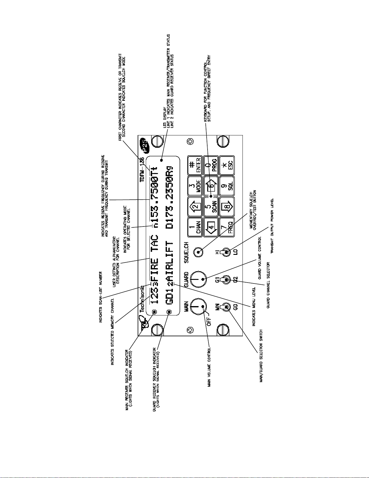
FIGURE 2-1 Operator's Switches and Controls - TDFM-136
2.3 DISPLAY INFORMATION
The display is divided into two (2) lines, the upper line displays information pertaining to the MAIN channel, the
lower line displays information about the GUARD channel. The information displayed is similar for both the MAIN
and GUARD and is formatted out as follows: (refer to figure 2-1).
The first three characters of the display indicate the CHANNEL selected, for MAIN the allowable values are 001
to 250, for GUARD only GD1 or GD2 can be displayed.
The fourth character indicates the SCAN list status of the channel, this is true for the MAIN channel only. If the
selected channel is included in a scan list, then the scan list number (1-5) will be displayed in subscript.
The next nine (9) characters are spaces for a text DESCRIPTION of the channel.
The next character indicates the operating MODE of the radio as follows:
lower case 'w' indicates analog wide mode
lower case 'n' indicates analog narrow mode
upper case 'D' indicates project 25 digital operation.
The next eight (8) characters indicate the channel frequency in MHz. The final two (2) characters indicate the
SQUELCH mode and operation as follows:
For Receive Operation
Rx indicates no squelch mode has been chosen
Rt indicates that CTCSS tones are being used
Rc indicates that DCS codes are being used
Rg indicates that project 25 TALK GROUPS are being used
Rn indicates that NOISE Squelch is being used.
For Transmit Operation
Tx indicates no squelch mode has been chosen
Tt indicates that CTCSS tones are being used
Tc indicates that DCS codes are being used
Tg indicates that project 25 TALK GROUPS are being used
there is no noise squelch mode for transmit!
2.4 BASIC RADIO OPERATION
Upon turning on the radio, after the boot sequence is finished the operator sees a two line display the top line of
which presents the operating parameters of the main channel, the bottom line of which presents the operating
parameters of the chosen guard channel.
The operator can receive signals from two (2) sources simultaneously: the selected MAIN receive (Rx) frequency
and the selected GUARD Rx frequency.
The operator may transmit on one (1) frequency at a time, the transmit (Tx) frequency is determined by the position
of the MN/GD switch. If set to ‘MN’ then the unit will transmit on the Tx frequency of the selected MAIN channel.
If the MN/GD switch is set to ‘GD’ then the unit will transmit on the Tx frequency of the selected GUARD channel.
The display will alter – on the appropriate line - to display the Tx frequency and squelch mode when the user
presses the press-to-talk (PTT) switch.
The operator selects the guard channel used via the front panel GD1/GD2 switch. Transmit occurs at a power level
as determined by the position of the HI/LO power switch: HI is 10 watts, LO is 1 watt.
The user may cause the radio to defeat the squelch on both selected MAIN and GUARD channels by pressing –
2-3

and holding – the SQUELCH button. Upon release, the saved squelch parameters will be restored to the respective
channels.
2.5 OPERATOR COMMANDS - OVERVIEW
The operator may affect the operation of the radio parameters by pressing the associated key on the keypad. The
parameters that may be affected in this manner are shown in the table below.
Table 2-1 TDFM-136 Command Matrix
Key operator direct – L1 operator programming– L2 maintenance – L3
1 select CHANNEL program CHANNEL select boot CHANNEL
2 display – brighter edit chan DESCRIPTION PC upload
3 edit chan MODE LOCK keypad RF Alignment
4 chan scroll down fast GD prog fast GD prog E/D
5 edit chan SCAN scan ON/OFF scan E/D
6 chan scroll up PTT timer E/D PTT timer set
7 edit chan FREQUENCY FREQUENCY scroll reserved
8 display – dimmer FREQ split/Rx simplex PC download
9 edit chan SQUELCH reserved terminal mode
0 go to level L2 go to level L3 reserved
ENTER save channel reserved reserved
ESC go to security - m go to previous level go to previous level
The commands are divided into levels: level one is a direct entry level, commands in this level are selected
directly by pressing a key. Level 2 commands are accessed by first pressing the ‘PROG’ (0) key. Level 3
commands allow personnel to maintain and configure the radio. To avoid accidental activation, these
commands are accessed by pressing the ‘ESC’ key followed by: ‘0’, ‘0’, ‘0’, ‘ENTER’.
2.6 USING OPERATOR DIRECT COMMANDS (Level 1)
1 (CHAN) - Select the Operating Channel
This command allows the user to select the MAIN channel that the radio is operating on. Upon selecting this
command the cursor will appear at the first digit in the channel number, select a number from 001 to 250.
‘ENTER’ – accepts this entry if valid (programmed) and will return standby condition. If the
cursor remains then this channel number is not valid or there is no information
programmed for the channel.
‘ESC’ - abandons the command and returns to the standby condition.
2 (UP ARROW) - Increased Display Brightness
Press and hold the up arrow (2) key to increase the brightness of the LED display, it stops at maximum.
3 (MODE) - Edit Channel Operating Mode
This command will edit the Operating MODE of the selected channel; both MAIN and GUARD channels may
be edited and the channel to be edited is determined by the position of the MN/GD switch and the G1/G2
switch.
2-4

2.6 USING OPERATOR DIRECT COMMANDS (Level 1) - continued
Upon selecting this command the cursor will appear at the MODE position, the forward arrow (6) key allows the
user to scroll through the available modes one at a time. see the table below.
Table 2.2 Operating Modes
Channel Operating Mode Indicator
Analog Wide (25 kHz) ‘w’
Analog Narrow (12.5 kHz) ‘n’
Digital (12.5 kHz) ‘D’
‘ENTER’ – accepts this entry and returns.
‘ESC’ - abandons the entry and returns.
4 (BACK ARROW) - Scroll Down the Channel List
This command will scroll DOWN through the programmed channels until reaching the lowest channel
programmed, it will then wrap around and restart from the top.
5 (SCAN) - Edit Channel Scan List
This command will select the SCAN LIST - if any - that the selected channel is included in. The channel may
be included in any one of the five (5) scan lists that are supported.
numbers 0-5 – select the Scan List (0 for none)
‘ENTER’ – accepts this entry and returns.
‘ESC’ - abandons the entry and returns.
6 (FORWARD ARROW) - Scroll Up the Channel List
Use the forward arrow This command will scroll UP through the programmed channels until reaching the
highest channel programmed, it will then wrap around and restart from the bottom.
7 (FREQ) - Edit Channel Operating Frequency
This command will edit the Operating Frequency of the selected channel; both MAIN and GUARD
channels may be edited and the channel to be edited is determined by the position of the MN/GD switch and
the G1/G2 switch.
8 (DOWN ARROW) - Decreased Display Brightness
Press and hold the down arrow (8) key to decrease the brightness of the LED display, it stops at minimum.
9 (SQL) - Edit Channel Squelch Mode
This command will edit the Squelch Parameters of the selected channel; both MAIN and GUARD channels
may be edited and the channel to be edited is determined by the position of the MN/GD switch and the G1/G2
switch.
For the receiver select a Squelch mode
6 (forward arrow) – scroll through available Squelch Modes.
‘ENTER’ – accepts this entry.
‘ESC’ - abandons the entry.
2-5

2.6 USING OPERATOR DIRECT COMMANDS (Level 1) - continued
NOTE: Squelch modes available will depend on operating mode chosen. ie. analog modes will not offer P25
talkgroup as an option.
Table 2.3 Receive and Transmit Squelch Modes
Squelch Mode Receive Transmit
carrier Rx Tx
noise Rn - (Tx)
CTCSS Tones Rt Tt
DCS Codes Rc Tc
P25 Talkgroup Rg Tg
Enter a key number pertaining to the Squelch mode chosen, refer to the tables below.
‘ENTER’ – accepts this entry.
‘ESC’ - abandons the entry.
Once the Rx Squelch Mode has been chosen, the process is repeated for the Tx Squelch modes.
Table 2.4 Noise Level
Level Key Number
0 0
1 1
2 2
3 3
4 4
5 5
6 6
7 7
8 8
9 9
10 10
11 11
12 12
13 13
14 14
15 15
16 16
2-6

Table 2.5 CTCSS Tones Table 2.6 DCS Codes
Tone Key Number Code Key Number Code Key Number
67.0 1 23 1 315 43
69.3 2 25 2 331 44
71.9 3 26 3 343 45
74.4 4 31 4 346 46
77.0 5 32 5 351 47
79.7 6 43 6 364 48
82.5 7 47 7 365 49
85.4 8 51 8 371 50
88.5 9 54 9 411 51
91.5 10 65 10 412 52
94.8 11 71 11 413 53
97.4 12 72 12 423 54
100.0 13 73 13 431 55
103.5 14 74 14 432 56
107.2 15 114 15 445 57
110.9 16 115 16 464 58
114.8 17 116 17 465 59
118.8 18 125 18 466 60
123.0 19 131 19 503 61
127.3 20 132 20 506 62
131.8 21 134 21 516 63
136.5 22 143 22 532 64
141.3 23 152 23 546 65
146.2 24 155 24 565 66
151.4 25 156 25 606 67
156.7 26 162 26 612 68
162.2 27 165 27 624 69
167.9 28 172 28 627 70
173.8 29 174 29 631 71
179.9 30 205 30 632 72
186.2 31 223 31 654 73
192.8 32 226 32 662 74
203.5 33 243 33 664 75
206.5 40 244 34 703 76
210.7 34 245 35 712 77
218.1 35 251 36 723 78
225.7 36 261 37 731 79
229.1 41 263 38 732 80
233.6 37 265 39 734 81
241.8 38 271 40 743 82
250.3 39 306 41 754 83
254.8 42 311 42
2-7

2.6 USING OPERATOR DIRECT COMMANDS (Level 1) - continued
0 (PROG) - Menu Level Up
Pressing this key selects the next Higher Menu Level, the Menu Level is indicated in the 4 character position
th
on the lower row of the display. The Menu Level is indicated in subscript and is as follows:
Table 2.7 Keypad Menu Level
Level Display
1 direct blank
2 programming 2
3 maintenance 3
Upon pressing this key, the radio will remain in the new Command Level for 5 seconds, if there is no further
user input within this time frame then the radio will revert to the Direct Command Level. The Direct Command
Level (level 1) is the normal operating mode for the radio.
NOTE: The Operator Direct Command Level (level 1) is indicated by a blank space, this is the normal
operating mode of the radio.
‘ENTER’ – save changes to selected channel if any
If there have been changes made to the current operating channel, pressing ‘ENTER’ will allow the user to
save these changes to the channel memory.
‘ESC’ – Menu Level Down
Pressing this key selects the next Lower Menu Level, the Menu Level is indicated in the 4 character position
th
on the lower row of the display. The Menu Level is indicated in subscript and is as given in the table in ‘0’
above.
2-8

2.7 USING OPERATOR PROGRAMMING COMMANDS (Level 2)
Access the Operator Programming Command Level (level 2) by pressing the ‘PROG’ key from the
Operator Direct Command Level (level1) once. The Menu Level is indicated in the 4 character position on
th
the lower row of the display, this will indicate a subscript ‘2’.
Having selected the Operator Programming Command Level, the keys provide a new set of functions for the
operator as follows:
1 - Program Channel Information
This command allows the user to program all the information for an operating channel. If the selected channel
contains valid information then that information will be displayed.
The channel to be programmed depends on the position of the front panel switches: If the MN/GD switch is in
the ‘MN’ position then the Main channel will be edited, if it is in the ‘GD’ position then the Guard channel will be
edited depending on the position of the G1/G2 switch.
For each step below, if there is valid data in the field:
Pressing the ‘ENTER’ key will accept the entered value and proceed to the next step.
Pressing the ‘ESC’ key will proceed to the next step without accepting the entered value.
5 Enter a Channel number (001 to 250), press ‘ENTER’.
6 Enter a Scan List for the channel if desired, press ‘ENTER’.
7 Enter a Text Description for the channel (up to 9 characters)
Up/Down arrow keys scroll through the alphabet, right/left arrow keys allow editing, when done,
press ‘ENTER’.
8 Select the Operating Mode , scroll through options using the forward arrow (6), press ‘ENTER’.
9 Select a Rx Frequency in the range 136.0000 to 174.0000, press ‘ENTER’.
10 Select a Rx Squelch Mode , choose TONES, CODES etc as required, press ‘ENTER’. Note
that the available Squelch modes will be affected by the selected Operating Mode, that is, if
analog narrow Operating Mode was selected then the user cannot select P25 talkgroup as a
Squelch Mode.
11 repeat 5 & 6 for Tx.
2 – Edit Channel Description
This command allows the user to edit the text description for the selected channel. The arrow keys allow
editing as follows:
2 (up arrow) – scroll up through the alphabet
8 (down arrow) – scroll down through the alphabet
4 (back arrow) – move cursor backwards
6 (forward arrow) – move cursor forwards
‘ENTER’ – accepts this entry.
‘ESC’ - abandons the entry.
3 – Lock Keypad
This command locks the keypad to prevent accidental change to parameters of the radio unbeknownst to the
operator. This will disable all keyboard functions (except keyboard unlock). To unlock the keyboard, press and
hold the ‘ESC’ key until the display indicates "UNLOCK" (about 2 seconds).
2.7 USING OPERATOR PROGRAMMING COMMANDS (Level 2) - continued
2-9

4 – Fast Guard Program
This command transfers the displayed main memory positions’ parameters to the Guard Memory position
according to the position of the G1/G2 front panel switch.
The selected Guard channel will now contain the information from the selected Main channel memory.
This feature may be disabled via Maintenance Command (Level 3) ‘4’.
‘ENTER’ – accepts this transfer.
‘ESC’ - abandons the transfer.
5 – Scan Mode: ON/OFF
This command allows the user to start and stop the Scan operation.
Select Scan and follow the command key with a number from 0 to 5, this will start scanning using the selected
scan list, if 0 was selected then scanning will be terminated.
NOTE: Scan operation automates the process of selecting pre-programmed channels that have been saved to
memory, it DOES NOT sweep the frequency band!
6 – PTT Timer: Enable/Disable
This command toggles the operation of the PTT timer. When ENABLED, the timer will stop the unit from
transmitting after the programmed time-out period, this protects against accidental PTT lockup. The user can
re-start the timer by releasing PTT for a moment.
!CAUTION! When DISABLED the PTT timer will not protect against continuous transmission.
The default is: PTT Timer ENABLED.
7 – Frequency: Scroll Mode
This command places the unit into frequency scroll mode, when in scroll mode the frequency may be changed
as follows:
2 (up arrow) – scroll frequency up in 2.5 kHz. steps.
8 (down arrow) – scroll frequency down in 2.5 kHz. steps.
4 (back arrow) – scroll frequency down in 1 MHz. steps.
6 (forward arrow) – scroll frequency up in 1 MHz. steps.
‘ENTER’ – accepts this entry.
‘ESC’ - abandons the entry.
8 – Rx/Tx Simplex/Split Pair Operation
This command allows you to quickly change the transmit frequency, when operating on a split pair
(repeater/semi-duplex mode), to the receive frequency to allow direct communications.
ie/ If you are transmitting on 152.000 MHz and receiving 152.555 MHz, press 8 (in command level 2) to
transmit on 152.555 MHz.
To return to the split pair condition, you must recall the memory channel again.
‘ENTER’ – accepts this entry.
‘ESC’ - abandons the command and returns to the normal operating mode
2.7 USING OPERATOR PROGRAMMING COMMANDS (Level 2) - continued
2-10

9 – not currently used - reserved
0 (PROG) - Menu Level Up
Pressing this key selects the next Higher Menu Level, the Menu Level is indicated in the 4 character position
th
on the lower row of the display. The Menu Level is indicated in subscript and is as follows:
Table 2.8 Keypad Menu Level
Level Display
1 direct blank
2 programming 2
3 maintenance 3
Upon pressing this key, the radio will remain in the new Command Level for 5 seconds, if there is no further
user input within this time frame then the radio will revert to the Direct Command Level. The Direct Command
Level (level 1) is the normal operating mode for the radio.
‘ENTER’ – n/a
‘ESC’ – back one Menu Level – (to operator direct menu level)
2-11

2.8 USING MAINTENANCE COMMANDS (Level 3)
The Maintenance Command Level is available to allow configuration and testing of the radio in a bench test
environment. This command level may be disabled by removing the jumper Jn on the MCU board.
NOTE: this command level should NOT BE ENABLED when the radio is installed in the airframe.
This command level is for bench operation only and as such does not preserve the Normal Operating display
characteristics, that is: the Main and Guard displays are replaced by suitable command prompt information.
1 – Channel: Select Power-On Channel
This command toggles through the available power-on channel defaults. This allows selection of which channel
will be selected when the unit is turned on. The available choices are: the last used channel or the last
programmed channel.
The default is: last used channel.
2 – PC upload
Upload data from the radio to a PC. The unit must be connected to a PC running Windows 95, 98, or NT 4.0
and the TiL Radio Communications Software package.
3 – not currently used - reserved
4 – Fast Guard Program: Enable/Disable
This command allows the maintenance personnel to Enable or Disable the Fast Guard Program capability
(Level 2 command 4).
The default selection is: DISABLED.
5 – Scan Operation: Enable/Disable
This command allows the maintenance personnel to Enable or Disable the Scan function (Level 2, command
5). When Enabled, the Scan function operates normally, when Disabled, the Scan function cannot be started.
The default selection is: ENABLED.
6 – PTT Timer: Set Time
The PTT timer duration may be set using this command: select 0 – 9, this number is multiplied by 10 seconds
to yield a timer duration between 0 and 90 seconds.
Note that selecting 0 effectively disables the radio from transmitting.
‘ENTER’ – accepts this entry and returns.
‘ESC’ - abandons the entry and returns.
7 – not currently used - reserved
8 – PC download
Download channel data from a PC to radio. The unit must be connected to a PC running Windows 95, 98 or NT
4.0 and the TiL Radio Communications Software package.
2.8 USING MAINTENANCE COMMANDS (Level 3) - continued
2-12

9 – Terminal Mode
Put the TDFM-136 into Terminal Mode. This is a bench test mode and allows the maintenance personnel to
control the radio for testing.
‘ESC’ - abandons Terminal Mode and returns.
0 – not currently used - reserved
‘ENTER’ – not currently used - reserved
‘ESC’ – back one Menu Level – (to operator programming menu level)
SECTION 3
INSTALLATION INSTRUCTIONS
2-13
3.1 GENERAL
This section contains information and instructions for the correct installation of the TDFM136, VHF/FM Digital Transceiver.
Make certain that the correct frequencies are preprogrammed in accordance with the
equipment user's valid FCC operator's license, prior to installation.
3.2 EQUIPMENT PACKING LOG
Unpack the equipment and check for any damage that may have occurred during transit.
Save the original shipping container for returns due to damage or warranty claims. Check that
each item on the packing slip has been shipped in the container. Verify that the equipment
display and backlighting configuration are the same as those ordered.
3.3 TRANSCEIVER INSTALLATION
The TDFM-136 Transceivers are designed to be Dzus mounted and should be installed in
conjunction with a IN-150 installation kit. See Figure 3-1 for an outline drawing of the unit with
dimensions to facilitate the installation.
3.4 INSTALLATION KIT - CONTENTS
The IN-150 installation kit consists of:
1. One 15 pin Cannon D mating connector (female) complete with crimp pins and hood.
2. One BNC antenna mating RF connector (male) and hood.
3.5 ANTENNA INSTALLATION
Antenna, P/N ATM-150 may be obtained from Technisonic Industries Limited or a suitable
equivalent 0dB gain antenna may be utilized with the TDFM-136 transceivers. The antenna
should be mounted on the bottom of the aircraft whenever possible and must be located at least
20cm (8 inches) from any occupant in the airframe. Consult with instructions provided with the
antenna. Connect RF cable from antenna to the back of the TDFM-136 unit by utilizing the BNC
mating connector provided in the installation kit.
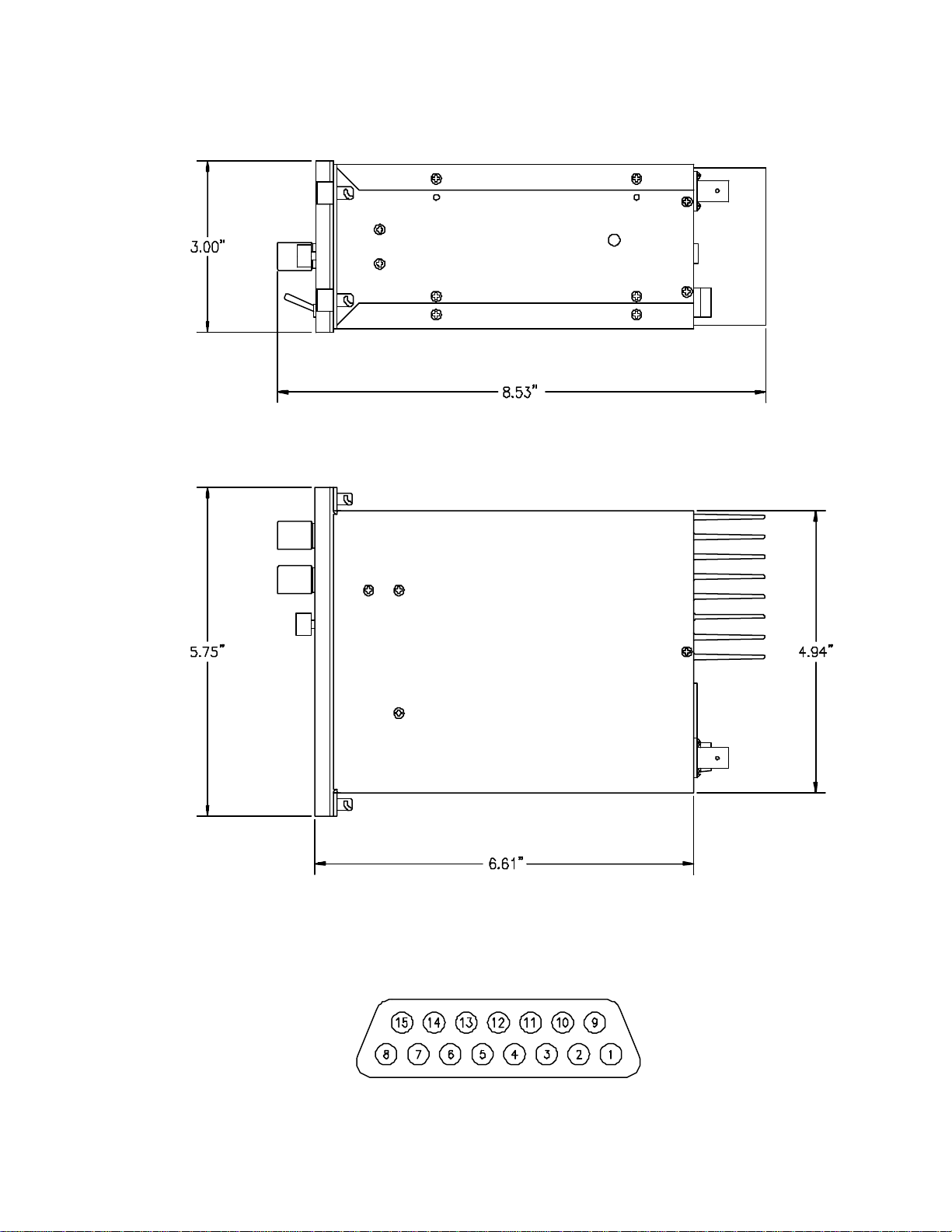
3.6 INSTALLATION - PIN LOCATIONS AND CONNECTIONS
The pin numbers and locations for the 15 pin Cannon D located on the rear of the TDFM136 digital transceivers are shown below. Pin connections are in provided in TABLE 3-1.
Transceiver mounted view of 15 pin connector
3-1

FIGURE 3-1 Outline Drawing for Model TDFM-136 Transceiver
3.6 INSTALLATION - PIN LOCATIONS AND CONNECTIONS (continued)
3-2

TDFM-136 Transceiver
15-Pin D Connections
Pin # Description
1 600 Ohm Output
2 Data Output
3 Panel Lighting (28VDC or 5VAC)
4 Memory UP/PC Download Input
5 Memory Down/PC Download Input
6 Mic Signal Input
7 Main Power +28VDC
8 Main Ground
9 4 ohm Speaker Output
10 4 ohm/600 ohm Output Ground
11 Data Input
12 PC Download Input
3.7 WIRING INSTRUCTIONS
Figure 3-2 shows all required connections and recommended wire sizes for the TDFM-136
Transceiver.
3.7.1 Main Power +28VDC
The main power +28VDC (±15%) is connected to pins 7 and 14 of the transceiver. Both
pins should be connected.
3.7.2 Main Ground
Ground connections for the transceiver are made on pins 8 and 15. Both pins should be
connected.
13 PTT (Ground Keying)
14 Main Power +28VDC
15 Main Ground
TABLE 3-1
3.7.3 PTT (Ground Keying)
The PTT line is connected to pin 13 and should be floating when the transceiver is in receive
mode, and grounded during transmit mode.
3-3
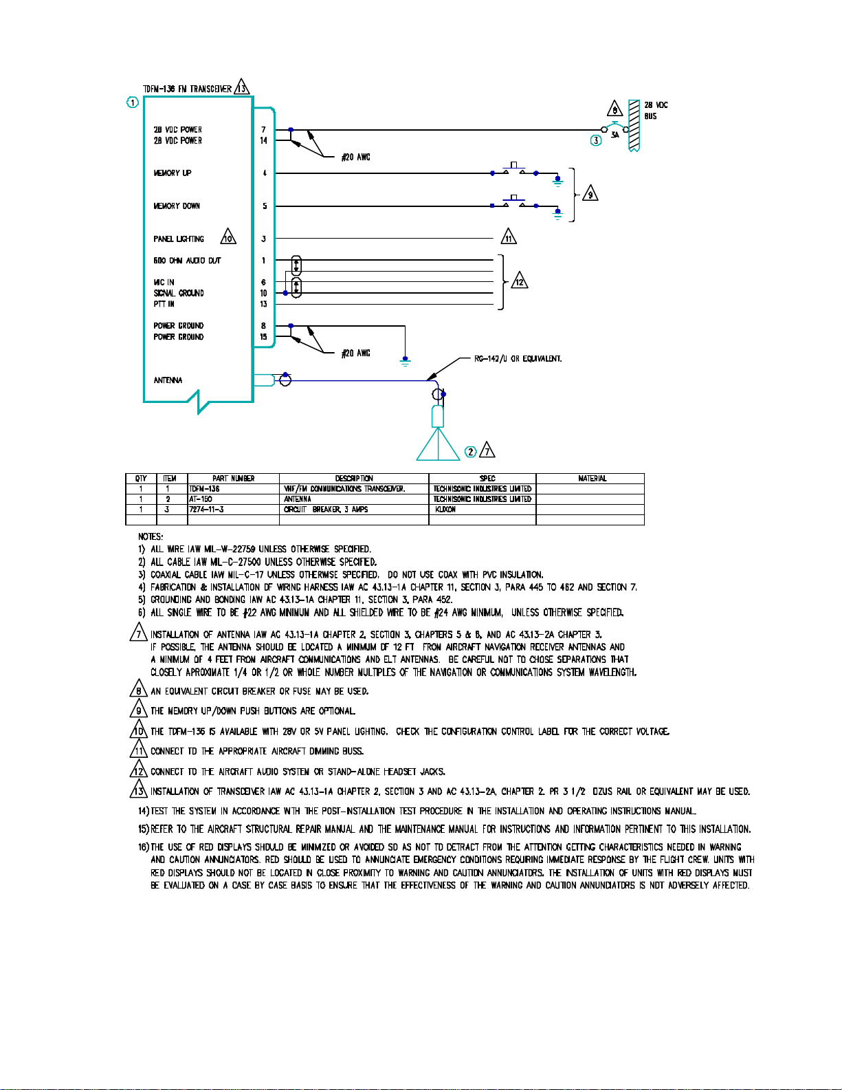
Figure 3-2 Wiring Connections for TDFM-136 Transceiver
3-4

3.7.4 Front Panel Back Lighting
Front panel back lighting connection should be made on pin 3 of the transceiver. The opposite
end of this lead should be connected to the panel lighting system of the aircraft. Before
connecting, verify the required panel lighting voltage (28 VDC or 5VAC) on the transceiver
configuration control label.
3.7.5 Audio Outputs (600 ohms and 4 0hms)
The audio output from pin 9 can be used to drive a 4 ohm speaker up to 2.5 watts. Audio
output from pin 1 is 600 ohms, 0.5 watts maximum.
3.7.6 Audio Output Ground
Pin 10 is the ground for both the 4ohm and 600 ohm audio output signals on pins 9 and 1.
3.7.7 Mic Signal Input
The microphone input signal is to be provided on pin 6, utilizing shielded wire with the shield
grounded to pin 10.
3.7.8 Memory Up/Memory Down
Remote scrolling through the 150 memory positions can be achieved by providing a ground to
pins 4 (up) and 5 (down) through a momentary contact cyclic switch.
3.7.9 Data Input
Channel data may be transferred to and from the unit using RS-232 communications protocol via
pins 2 and 11.
3-5

3.8 TRANSMITTER SIDETONE LEVEL ADJUSTMENT
1. Set the transceiver operating frequency to 155.000 MHz and connect an appropriate test
receiver to the RF output connector. Ensure that the output of the transceiver is
terminated into a proper dummy load.
2. Key the transmitter and input a -10 dBm (0.25 VRMS), 1 KHz audio signal into the
microphone input.
3. Select the sidetone adjust command and then adjust the sidetone level using the guard
volume control to produce a +3.0 dBm (1.0 VRMS) 600 ohm audio output.
3.9 MAIN AND GUARD SQUELCH ADJUSTMENT
The squelch on both the main and guard receivers is factory set to open at approximately
0.5 microvolts. This adjustment can be made or altered to suit local conditions as follows:
1. Set the main receiver of the transceiver to 155.000 Mhz. Connect a signal generator to
the antenna input of the transceiver.
2. Set the signal generator to produce a ±3 KHz deviation with a 1 KHz tone on 156.000
MHz. Increase the signal generator RF level from 0.1 uV until the squelch indicator LED
is on. Verify the receiver SINAD ratio is between 12 and 14 dB.
3. If not, re-adjust main receiver squelch via the main receiver squelch software command.
4. Repeat the above procedure to adjust the guard receiver squelch setting using guard
receiver squelch adjustment software command.
3-6
 Loading...