

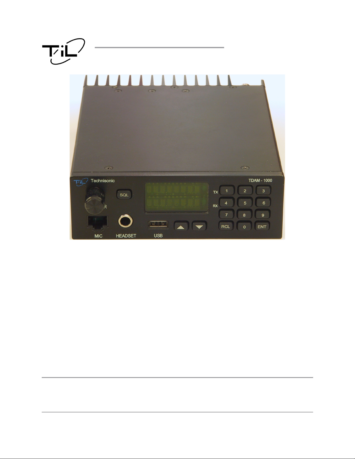
VHF AM TRANSCEIVER
TDAM-1000
Installation and Operating
Instructions
TiL Document No. 15RE532
Rev. C
November 2018
Technisonic Industries Limited
240 Traders Boulevard, Mississauga, Ontario L4Z 1W7
Copyright by Technisonic Industries Limited. All rights reserved.
Tel: (905) 890-2113 Fax: (905) 890-5338
www.til.ca

TECHNISONIC INDUSTRIES LIMITED
This page is intentionally left blank.
TDAM-1000 Installation and Operating Instructions TiL 15RE532 rev. C
ii

TECHNISONIC INDUSTRIES LIMITED
REVISION HISTORY
[ 15RE532 ]
REV
SECTION
- PAGE -
DESCRIPTION DATE
N/C
A
All
Original Document Release.
Updated to final installation and operation for
8 Jan 2016
24 May 2018
production release.
B All Updated for IC and FCC conformance. 22 June 2018 SM
C V Updated FCC Compliance notes 1 Nov 2018 SM
EDITED
BY
SM
SM
TDAM-1000 Installation and Operating Instructions TiL 15RE532 rev. C
iii

TECHNISONIC INDUSTRIES LIMITED
This page is intentionally left blank.
TDAM-1000 Installation and Operating Instructions TiL 15RE532 rev. C
iv

TECHNISONIC INDUSTRIES LIMITED
WARNING:
NOTES
ESD CAUTION
This unit contains static sensitive devices. Wear a grounded wrist strap and/or conductive gloves
when handling printed circuit boards.
FCC COMPLIANCE INFORMATION
This device complies with Part 15 of the FCC Rules. Operation is subject to the following two conditions:
(1) this device may not cause harmful interference and (2) this device must accept any interference
received, including interference that may cause undesired operation.
antenna installation shall comply with the following two conditions:
1. The transmitter antenna gain shall not exceed 3 dBi.
2. The transmitter antenna is required to be located outside of a vehicle and kept at a separation distance of
115 cm or more between the transmitter antenna of this device and persons during operation.
NOTE: This equipment has been tested and found to comply with the limits for a Class B digital device,
pursuant to part 15 of the FCC Rules. These limits are designed to provide reasonable protection against
harmful interference in a residential installation. This equipment generates, uses and can radiate radio
frequency energy and, if not installed and used in accordance with the instructions, may cause harmful
interference to radio communications. However, there is no guarantee that interference will not occur in a
particular installation. If this equipment does cause harmful interference to radio or television reception,
which can be determined by turning the equipment off and on, the user is encouraged to try to correct the
interference by one or more of the following measures:
—Reorient or relocate the receiving antenna.
—Increase the separation between the equipment and receiver.
—Connect the equipment into an outlet on a circuit different from that to which the receiver is connected.
—Consult the dealer or an experienced radio/TV technician for help.
WARNING AND DISCLAIMER
Changes or modifications not expressly approved by Technisonic Industries could void the user’s
authority to operate the equipment.
This manual is designed to provide information about the TDAM-1000. Every effort has been made to
make this manual as complete and accurate as possible.
WARRANTY INFORMATION
The Model TDAM-1000 is under warranty for one year from date of purchase. Failed units caused by
defective parts or workmanship should be returned to:
Technisonic Industries Limited
240 Traders Boulevard
Mississauga, Ontario L4Z 1W7
Tel: (905) 890-2113
Fax: (905) 890-5338
TDAM-1000 Installation and Operating Instructions TiL 15RE532 rev. C
For compliance with FCC RF Exposure Requirements the mobile transmitter
v

TECHNISONIC INDUSTRIES LIMITED
SECTION
TITLE
PAGE
FIGURE
TITLE
PAGE
TABLE
TITLE
PAGE
TABLE OF CONTENTS
1 GENERAL DESCRIPTION B
1.1 INTRODUCTION ............................................................................................................... 1
1.2 DESCRIPTION .................................................................................................................. 1
1.3 SYSTEM COMPONENTS ................................................................................................. 1
2 INSTALLATION INSTRUCTIONS B
2.1 GENERAL ......................................................................................................................... 3
2.2 EQUIPMENT PACKING LOG ........................................................................................... 3
2.3 TDAM-1000 INSTALLATION ............................................................................................ 3
2.4 INSTALLATION CONNECTIONS ..................................................................................... 5
2.5 INSTALLATION - WIRING INSTRUCTIONS .................................................................... 6
3 OPERATING INSTRUCTIONS B
3.1 GENERAL ......................................................................................................................... 7
3.2 FEATURES ....................................................................................................................... 7
3.3 FRONT PANEL ................................................................................................................. 7
3.4 NORMAL OPERATION ..................................................................................................... 8
3.5 FUNCTION MENU ............................................................................................................ 10
3.6 CONFIGURATION MENU ................................................................................................. 11
3.7 25 AND 8.33 kHz CHANNEL SPACING ........................................................................... 12
4 SPECIFICATIONS B
4.0 DIMENSIONS .................................................................................................................... 13
4.1 GENERAL SPECIFICATIONS .......................................................................................... 13
4.2 RECEIVER SPECIFICATIONS ......................................................................................... 14
4.3 TRANSMITTER SPECIFICATIONS .................................................................................. 15
WARRANTY ...................................................................................................................... 16
LIST OF FIGURES
1 Outline Drawing for Model TDAM-1000 ............................................................................ 4
2 Wiring Connections and Notes for the TDAM-1000 .......................................................... 5
3 TDAM-1000 Front Panel Controls ..................................................................................... 7
LIST OF TABLES
1 Power Connections (2 Pin D-Connections – J1) ............................................................... 5
2 Accessory Connections (15 Pin D-Connections – J7) ...................................................... 5
TDAM-1000 Installation and Operating Instructions TiL 15RE532 rev. C
vi

TECHNISONIC INDUSTRIES LIMITED
This page is intentionally left blank.
TDAM-1000 Installation and Operating Instructions TiL 15RE532 rev. C
vii

TECHNISONIC INDUSTRIES LIMITED
SECTION 1: GENERAL DESCRIPTION
1.1 INTRODUCTION
This publication provides information on the installation and operation of the TDAM-1000
Transceiver.
1.2 DESCRIPTION
The TDAM-1000 VHF AM mobile transceiver (Product Marketing Name (PMN) TDAM-1000)
operates in the aeronautical VHF AM band and is designed for ground vehicle installation.
1.3 SYSTEM COMPONENTS
The following components make up the system:
TDAM-1000 VHF AM Transceiver
Microphone Assembly
Mounting Bracket
Mobile Antenna Assembly
Power Cord
Installation Kit
151286-1
181298-1
169676
181299-1
183043-1
189729
TDAM-1000 Installation and Operating Instructions TiL 15RE532 rev. C
1

TECHNISONIC INDUSTRIES LIMITED
This page is intentionally left blank.
TDAM-1000 Installation and Operating Instructions TiL 15RE532 rev. C
2

TECHNISONIC INDUSTRIES LIMITED
SECTION 2: INSTALLATION INSTRUCTIONS
2.1 GENERAL
This section contains information and instructions for the correct installation of the TDAM-1000
VHF AM transceiver.
2.2 EQUIPMENT PACKING LOG
Unpack the equipment and check for any damage that may have occurred during transit. Save
the original shipping container for returns due to damage or warranty claims. Check that each
item on the packing slip has been shipped in the container.
2.3 INSTALLATION
The TDAM-1000 is designed to be used in land mobile applications. A mounting bracket, hand
microphone, power cable and antenna are supplied. The TDAM-1000 will operate on both
standard 13.8 VDC or 28 VDC special purpose or military vehicle power without modification. The
built in speaker is sufficient for most installations however a 7 watt external speaker output is
supplied for high noise environments.
TDAM-1000 Installation and Operating Instructions TiL 15RE532 rev. C
3

TECHNISONIC INDUSTRIES LIMITED
FIGURE 1 - Outline Drawing for Model TDAM-1000
TDAM-1000 Installation and Operating Instructions TiL 15RE532 rev. C
4

TECHNISONIC INDUSTRIES LIMITED
2.4 INSTALLATION - CONNECTIONS
FIGURE 2 - Rear Connector View - TDAM-1000
J1 (2 Pin D Connections) - Use Plug
Pin # Description
1
2
Power
Ground
TABLE 1. Power Plug Connections
J7 (15 Pin D Connections) - Use MALE Connector
Pin # Description
1
2
3
4
5
6
7
8
9
10
11
12
13
14
15
Speaker +
Speaker -
Monitor Audio
Headset Audio
Cross Mute Out
Mic Audio
PTT
Ground
CAN Low
CAN High
Squelch
TX Data
RX Data
Cross Mute In
Ground
TABLE 2. Accessory Plug Connections
TDAM-1000 Installation and Operating Instructions TiL 15RE532 rev. C
5

TECHNISONIC INDUSTRIES LIMITED
2.5 INSTALLATION - WIRING INSTRUCTIONS
For most installations, only the power connection and the antenna connection are required.
However an installation of two TDAM-1000 transceivers can take advantage of the ‘Cross Mute’
feature available on the 15 pin D connector. The Cross Mute function will mute the other receiver
whenever one of the radios is transmitting.
2.5.1 J1 PINS 1 AND 2 – MAIN POWER INPUT
Use supplied power cable to connect to vehicle accessory power source.
2.5.2 P1 PINS 1 AND 2 – SPEAKER OUTPUT
7 watt speaker output at 8 ohm impedance. The speaker output includes receive audio only. The
Level is set by the volume control.
2.5.3 P1 PIN 3 – MONITOR AUDIO
Line level audio output receive and sidetone (mic) audio combined. Not affected by the volume
control.
2.5.4 J1 PIN 4 – HEADSET AUDIO
0.5 watt 600 ohm audio output. Includes receive and sidetone (mic) audio. The level is set by
the volume control.
2.5.5 P1 PIN 5 – CROSS MUTE OUTPUT
10 volt output during transmit and 0 volts during receive.
2.5.6 P1 PIN 6 – MIC AUDIO INPUT
Microphone audio input. Mic DC bias voltage is supplied.
2.5.7 P1 PIN 7 – PTT INPUT
Push to talk input. Radio will transmit when this line is brought to ground.
2.5.8 P1 PINS 8 AND 15 – GROUND
Ground. Connected to signal and chassis ground.
2.5.9 P1 PINS 9 AND 10 – CAN BUS INTERFACE
Do not connect.
2.5.10 P1 PIN 11 – SQUELCH OUTPUT
Squelch signal output. Open collector output which goes to ground when squelch is open.
2.5.11 P1 PINS 12 AND 13 – TX AND RX DATA
Serial RS-232 interface for base station applications. Do not connect.
2.5.12 P1 PIN 14 – CROSS MUTE INPUT
Receive audio will be muted on the speaker, headset and monitor outputs when this input is at 10
volts.
TDAM-1000 Installation and Operating Instructions TiL 15RE532 rev. C
6

SECTION 3: OPERATING INSTRUCTIONS
3.1 GENERAL
This section contains information and instructions for the correct operation of the TDAM-1000
transceiver.
3.2 FEATURES
The TDAM-1000 supports the following features:
• 16 character LED alphanumeric display
• Backlit panel and keys
• USB port for loading and saving channel or configuration data.
• Continuous coverage from 117.975 to 138.000 MHz in 25 or 8.33 kHz steps.
• 100 programmable channels
• Split frequency pairs
• Transmit DTMF keypad
• Scanning of selected channels
• High and Low power
3.3 FRONT PANEL
Refer to figure 2 below:
TECHNISONIC INDUSTRIES LIMITED
FIGURE 3. Front Panel Controls
3.3.1 VOLUME KNOB
The volume knob has a push button built in which is used to turn the radio on and off as well as
select other functions for the knob. To turn on the radio, press and hold the knob until the display
lights up. To turn off the radio, press and hold the knob for approximately 3 seconds until the
display shows ‘OFF’. Quick presses of the knob during normal operation will toggle the knob
function between volume, channel, squelch and brightness modes. The default mode for the knob
is volume when the radio is turned on.
TDAM-1000 Installation and Operating Instructions TiL 15RE532 rev. C
7

TECHNISONIC INDUSTRIES LIMITED
3.3.2 SQUELCH BUTTON
The squelch function mutes the receiver when no signal is present so the operator does not listen
to continuous receiver noise. When the knob is in squelch mode, it adjusts the muting threshold
from fully open to a level where only a strong signal can be heard. Pressing the squelch button
will temporarily open the squelch for as long as the button is pressed. When released, the knob is
put into squelch mode for 3 seconds with the squelch level shown on the bottom line of the
display.
3.3.3 LED DISPLAY
The display is a 2 line 16 character green LED type. During normal operation the frequency,
channel name and/or channel number may be displayed depending on settings in the
configuration menu. The display is also used during programming and menu functions. There are
two LED indicators on the right of the display for transmit and receive (squelch open).
3.3.4 KEYPAD
A numeric keypad is provided to allow quick entry of frequencies or program channels.
3.3.5 CHANNEL UP/DOWN KEYS
These keys are used to select the desired channel.
3.3.6 USB CONNECTOR
The USB connector can be used to upload or download a channel list, program the radio
configuration or update the radio firmware.
3.3.7 MIC AND HEADSET JACKS
The supplied hand mic is plugged into the RJ-45 type jack. Headphones if desired can be
plugged into the headset jack. The internal speaker and external speaker output can be disabled
(default) when the headset jack is used depending on the settings in the configuration menu.
3.4 NORMAL OPERATION
Note: The TDAM-1000 transceiver can be configured to operate in one of two modes:
1. Frequency agile mode – Any frequency from 117.975 to 138.000 MHz can be selected or
programmed into any of the 100 available channels.
2. Fixed mode – Only frequencies programmed into channels can be used.
The operating mode can be set in the configuration menu. The following instructions assume
frequency agile mode. Those marked with an asterisk (*) will not be available in fixed mode.
3.4.1 ENTERING A FREQUENCY*
The TDAM-1000 supports both 25 kHz and 8.33 kHz channel spacing. The channel spacing used
is determined by the frequency entered. See the ICAO frequency chart in table x.x.
To enter a new frequency, type in the frequency (up to 6 digits) via the keypad and press enter. If
enter is not pressed within 3 seconds or the mic is keyed, the radio will revert back to the
previous frequency. For example, to enter 128.75 press:
The new frequency is ready to use. The new frequency is not saved in a channel but will remain
active until another frequency or channel is selected.
TDAM-1000 Installation and Operating Instructions TiL 15RE532 rev. C
8

TECHNISONIC INDUSTRIES LIMITED
3.4.2 PROGRAMMING A CHANNEL*
To program a channel, type in the frequency (up to 6 digits) via the keypad and press enter. Then
enter the channel number (1-100) and press enter again. For example, to program 128.75 into
channel 48, press:
The channel is programmed and the radio is ready to use on the above frequency. If the second
enter is not pressed or the mic is keyed within 3 seconds, the new frequency will not be saved in
a channel.
3.4.3 RECALLING A CHANNEL
A channel can be recalled in one of 3 ways:
1. Rotating the volume knob while in channel mode.
2. Using the channel up/down keys.
3. Using the recall key and number keys.
3.4.4 RECALLING A CHANNEL WITH THE VOLUME KNOB
Press the volume knob until the lower line of the display shows CHAN. Rotate the volume knob
until the desired channel is displayed. Only channels which have been programmed will be
displayed.
3.4.5 RECALLING A CHANNEL WITH THE CHANNEL UP/DOWN KEYS
Press the up or down channel key until the desired channel is displayed. If the previous frequency
was not in a channel, the channel number will start with that last channel used.
3.4.6 RECALLING A CHANNEL WITH THE RECALL FEATURE
Press the recall key followed by the channel number (1, 2 or 3 digits). Press enter within 3
seconds. For example, to recall channel 48, press:
The radio is ready to use on channel 48. If channel 48 was unprogrammed, the radio will stay at
the channel it was on.
3.4.7 DELETING A CHANNEL*
Recall the channel desired channel using one of the above methods. Press 0 and enter. The
lower line of the display will read ‘DELETE?’. Press enter again to confirm. For example, to delete
channel 48, press:
The radio will then tune to the next lower channel number available
TDAM-1000 Installation and Operating Instructions TiL 15RE532 rev. C
9

3.5 FUNCTION MENU
The Function Menu is invoked by pressing the enter key. The display will respond with ‘Menu #’.
Press one of the following keys for the associated function:
Begin entry of transmit frequency. Current channel will be modified with new
transmit frequency, receive frequency will remain unchanged allowing for split
frequency operation.
Enable or disable scanning for the currently selected channel.
Enable or disable transmit for the selected channel. Allows for receive only
channels to be defined.
Edit the text name for the currently selected channel. Rotate knob or use up/down
keys to select character under cursor. Press the knob or ENT key to proceed to
the next character. Text will be saved after the last character is set.
Toggle seek mode on or off. Channels enabled in function 2 will be scanned until
an active channel is encountered at which point the seek mode will set to off and
normal operation will resume.
Toggle scan mode on or off. Channels enabled in function 2 will be scanned until
an active channel is encountered. The radio will stay on that channel for a time
programed in the configuration menu. Transmit is possible during scanning, the
frequency depends on the mode programed in the configuration menu. Scanning
will continue indefinitely until function 6 is selected to toggle scan mode off.
Toggles transmit power low or high. (1 watt or 10 watts)
Copy current channel to a new specified channel. The radio will prompt you for
the new channel number. The current channel will remain unchanged.
Adjust display and back lighting brightness. When selected, the knob becomes
the brightness control.
Enter configuration menu. See 3.6 CONFIGURATION MENU.
Read channel or configuration data from USB storage device into radio.
Save channel or configuration data to USB storage device from radio.
TECHNISONIC INDUSTRIES LIMITED
TDAM-1000 Installation and Operating Instructions TiL 15RE532 rev. C
10

TECHNISONIC INDUSTRIES LIMITED
3.6 CONFIGURATION MENU
The Configuration Menu is invoked by pressing the 0 key in the function menu. The display will
respond with ‘Config’. Turn the knob to select the desired item and press the knob to edit the
item. Configuration menu items include:
Mem Disp Allows the format of the display for programmed channels to be selected:
Freq Displays the frequency on the top line only.
Freq-# Displays the frequency on the top line and the channel
Freq-Name Displays the frequency on the top line and the name of
Name-# Displays the channel name on the top line and the
AlwaysOn Power switch configuration:
No Knob must be used to turn the radio on and off.
Yes Radio is always on when power is applied.
Comp Lvl Microphone compression level. Turning the knob will adjust (range 0 – 1023)
the maximum gain of the microphone input.
Ext Spkr External speaker operating mode:
Off External speaker output is off at all times.
Rx Only External speaker outputs receive audio only.
Rx & Tx External speaker outputs receive and transmit audio.
Ext Vol External speaker volume mode:
IntSpkr= External speaker volume is equal to the internal speaker.
Separate External speaker volume is separately adjustable.
FrqAgile Frequency agile mode:
No Only programmed channels can be selected.
Yes Programming and direct frequency entry is allowed.
HdstMute Headset mute mode:
No Spkr Neither speaker is muted when the headset plug inserted.
Int Spkr Only the internal speaker is muted when the headset plug
Ext Spkr Only the external speaker output is muted when the
BothSpkr Both internal and external speakers are muted when the
Mod Lvl Modulation level. Adjusts the transmit modulation level. (range 0 – 2250)
Mon Vol Monitor volume. Adjusts the level of the monitor output. (range 0 – 255)
Scan Mon Scan monitor time. Adjusts the number of seconds (0 – 90) the radio will
remain on an open frequency during scanning.
ScanRply Scan reply time. Adjust the number of seconds (0 – 90) the radio will stay on a
frequency after the squelch has closed before resuming scanning.
ScanRvrt Scan revert mode:
Selected All replies are transmitted on the frequency selected
Contacted All replies are transmitted on the frequency of the last
Tx Timer Transmit timer. Selects the transmit timeout timer between Off, 30, 60 or 90
seconds.
number on the bottom line.
the channel on the bottom line.
channel number on the bottom line.
is inserted.
headset plug is inserted.
headset plug is inserted.
before scanning was enabled.
channel received.
TDAM-1000 Installation and Operating Instructions TiL 15RE532 rev. C
11

TECHNISONIC INDUSTRIES LIMITED
3.7 25 AND 8.33 kHz CHANNEL SPACING
The TDAM-1000 is capable of both 25 and 8.33 kHz channel spacing. Selecting the desired
channel spacing is achieved during the frequency entry procedure. The TDAM-1000 uses the
ICAO standard where 5, 10 or 15 kHz is added to the 25 kHz channel frequencies to represent
the additional 8.33 kHz channel steps:
Frequency Entered Actual Frequency Channel Spacing
118.000 118.000 MHz 25 kHz
118.005 118.000 MHz 8.33 kHz
118.010 118.00833 MHz 8.33 kHz
118.015 118.01666 MHz 8.33 kHz
118.025 118.025 MHz 25 kHz
118.030 118.025 MHz 8.33 kHz
118.035 118.03333 MHz 8.33 kHz
118.040 118.04166 MHz 8.33 kHz
118.050 118.050 MHz 25 kHz
118.055 118.050 MHz 8.33 kHz
118.060 118.05833 MHz 8.33 kHz
etc etc etc
TDAM-1000 Installation and Operating Instructions TiL 15RE532 rev. C
12

TECHNISONIC INDUSTRIES LIMITED
SECTION 4: SPECIFICATIONS
4.0 DIMENSIONS
Width
Height
Depth
Weight
4.1 GENERAL SPECIFICATIONS
Frequency Band
Modulation
Channel Spacing
Frequency Stability
Operating Temperature
Storage Temperature
Power Consumption
Transmit High Power
Receive
Standby
5.4 inches (137 mm)
1.8 inches (46 mm)
7.7 inches (196 mm)
2.8 lbs (1.27 kg)
117.975 – 138.000 MHz
AM (A3E)
25 kHz and 8.33 kHz
+/- 1 ppm (0.0001%)
-20 to +55 °C
-40 to +70 °C
< 65 Watts
< 15 Watts
< 10 Watts
TDAM-1000 Installation and Operating Instructions TiL 15RE532 rev. C
13

TECHNISONIC INDUSTRIES LIMITED
4.2 RECEIVER SPECIFICATIONS
Sensitivity
Selectivity
25 kHz Channel Spacing
8.33 kHz Channel Spacing
Adjacent Channel Rejection
Spurious Attenuation
Blocking for 1 MHz Frequency Offset
Signal to Noise Ratio
Frequency Stability
Intermodulation Immunity
Image Frequency Rejection
Intermediate Frequency Rejection
Conducted Spurious
Cross Modulation Rejection
Squelch
Scanning
Audio Response
25 kHz Channel Spacing
8.33 kHz Channel Spacing
Audio Distortion
Audio Output Power
< 1µV for 12dB SINAD
> 65 dB @ ±25 kHz, < 6 dB @ ±8.5 kHz
> 60 dB @ ±8.33 kHz, < 6 dB @ ±2.5 kHz
> 60 dB
> 70 dB
> 80 dB
< 45 dB
1 ppm (0.0001%)
> 70 dB
> 100 dB
> 95 dB
< -70 dB
> 70 dB @ 100kHz Frequency Offset
Adjustable 0 to 25 µV
20 Channels per Second
300 to 3400 Hz, +1 dB, -2dB
350 to 2500 Hz, +1 dB, -2 dB
< 5% THD
> 7 Watts
TDAM-1000 Installation and Operating Instructions TiL 15RE532 rev. C
14

TECHNISONIC INDUSTRIES LIMITED
4.3 TRANSMITTER SPECIFICATIONS
RF Output Power
Modulation Depth
VSWR
Hum and Noise
Distortion
Frequency Stability
Intermodulation Attenuation
Keying Time
Release Time
Speech Processor
Selectable 1 or 10 Watts
Up to 95%
1:Infinity
> 40 dB @ 90% Modulation
< 5% @ 90% Modulation
±1 ppm (0.0001%)
40 dB @ 150 kHz Offset
< 20 ms
< 10 ms
35 dB Dynamic Range
TDAM-1000 Installation and Operating Instructions TiL 15RE532 rev. C
15

TECHNISONIC INDUSTRIES LIMITED
Technisonic Industries Limited
240 Traders Blvd., Mississauga, ON Canada L4Z 1W7
Tel: (905) 890-2113 Fax: (905) 890-5338
IMPORTANT
WARRANTY
All communication equipment manufactured by Technisonic Industries Limited is
warranted to be free of defects in Material or Workmanship under normal use for a period
of one year from Date of Purchase by the end user.
Warranty will only apply to equipment installed by a factory approved and/or authorized
facility in accordance with Technisonic published installation instructions. Equipment
falling under the following is not covered by warranty:
• Equipment that has been repaired or altered in any way as to affect performance,
• Equipment that has been subject to improper installation,
• Equipment that has been used for purposes other than intended,
• Equipment that has been involved in any accident, fire, flood, immersion, or subject to
any other abuse.
Expressly excluded from this warranty are changes or charges relating to the removal and
re-installation of equipment from the vehicle. Technisonic will repair or replace (at
Technisonic's discretion) any defective transceiver (or part thereof) found to be faulty
during the Warranty Period.
Faulty equipment must be returned to Technisonic (or its authorized Warranty Depot) with
transportation charges prepaid. Repaired (or replacement) equipment will be returned to
the customer with collect freight charges. If the failure of a transceiver occurs within the
first 30 days of service, Technisonic will return the repaired or replacement equipment
prepaid.
Technisonic reserves the right to make changes in design, or additions to, or
improvements in its products without obligation to install such additions and
improvements in equipment previously manufactured. This Warranty is in lieu of any and
all other warranties express or implied, including any warranty of merchantability or
fitness, and of all other obligations or liabilities on the part of Technisonic.
This Warranty shall not be transferable or assignable to any other persons, firms, or
corporations.
For warranty registration, please complete the online
Warranty Registration Form found at www.til.ca.
TDAM-1000 Installation and Operating Instructions TiL 15RE532 rev. C
16
 Loading...