


FRISTAR
Version 2.01 EN
Manual version 3
Fresh water station
Operating manual
en

Table of contents
Safety instructions .................................................................................................................... 3
Mode of operation .................................................................................................................... 4
Hydraulic circuit diagram...................................................................................................... 4
Components ............................................................................................................................. 5
Installation ................................................................................................................................ 6
Preparation .......................................................................................................................... 6
Installation ............................................................................................................................ 7
Commissioning ........................................................................................................................ 7
Dimensions .............................................................................................................................. 8
Connection of a circulation line ................................................................................................ 9
Interchanging connections ..................................................................................................... 10
Cascade switching ................................................................................................................. 11
Hydraulic circuit diagram of a cascade with four FRISTAR fresh water stations ................ 11
Cascade switching control with UVR61-3R or UVR63 ....................................................... 12
Control of cascade switching with UVR1611 ..................................................................... 13
Cascade switching with circulation line .................................................................................. 13
Hydraulics schematic diagram ........................................................................................... 13
Circulation pump (optional) .................................................................................................... 14
Electrical circuit diagram ........................................................................................................ 14
Controller settings .................................................................................................................. 15
Technical data ........................................................................................................................ 16
Pressure loss characteristic curve plate heat exchanger: .................................................. 17
Pressure loss characteristic pump ..................................................................................... 17
Plate heat exchanger corrosion resistance ........................................................................ 18

3
Safety instructions
These instructions are intended exclusively for authorised professionals. To avoid accidents and damage due to incorrect operation,
carefully read through these operating instructions before you start
working with the freshwater station. If you carry out any alterations to
the construction of the freshwater station or the safety devices, you
may invalidate your right to make guarantee claims. Always observe
the local regulations.
Intended use
The freshwater station may only be installed in heating systems between the buffer tank and
the drinking water circuit. The technical limit values specified in this manual must be consid-
ered.
Incorrect use will result in the negation of any liability claims.
Electrical connection
Any electrical connections must be made by qualified electricians. Connection cables must
be routed in the recesses provided in the insulated base in such a way that direct contact
with the pump casing and the pipes is prevented.
Before switching on, check whether the supply voltage matches that stated on the power rat-
ing plates of the pump and the controller. All connections must correspond to the local regu-
lations.
Safety standards during installation, commissioning and maintenance
Installation, commissioning and maintenance may only be carried out by qualified persons
who are familiar with these operating instructions.
Before you start work on the system, ensure that the system is switched off and all compo-
nents are cooled down. When replacing the pump, turn the 4 ball valves into the closed posi-
tion.
In multi-occupancy dwellings, legionella protection must be observed in accordance with the
local regulations.
WARNING! Dependent on the pump and system operating conditions, the sur-
face temperatures can be very high. Direct contact with the pump or pipes can
result in burns!
Important note:
The secondary flow rate (cold / hot water)
must never be more than 40 l/min!

4
Mode of operation
Through use of the instantaneous heating concept, drinking water is heated both hygienically
and with low energy consumption in the FRISTAR freshwater station.
If water is drawn from the mains, the primary circuit pump transports tank water from a buffer
tank through the plate heat exchanger.
On the secondary side of the heat exchanger the drinking water flowing through is heated to
the temperature set in the controller. The cooled tank water is returned to bottom layer of the
buffer tank.
The speed control of the primary circuit pump takes place in the FRISTAR controller based
on the measurements of the volume flow sensor in the hot water pipe (temperature Tww and
volume flow Vww) and the temperature sensor in the primary flow TPri). The pump is con-
trolled using wave packet control. The optimum matching of the control behaviour to the
pump and the heat exchanger guarantees perfect constant maintenance of the outlet temperature.
Hydraulic circuit diagram
Temperature
Primary flow
Volume flow sensor
Hot water temperature Tww
Volume flow Vww
Pre-mixer
(recommended)
Safety valve max. 8 bar
Pump

5
Components
Flow
primary circuit
Return
primary circuit
Ball valve
Ball valve
with
gravity brake
Ball valve
Ball valve
Hot water
Secondary circuit
Cold water
Secondary circuit
Volume
flow sensor
Primary
sensor
Controller
Pump
Power cable
Plate heat
exchanger
Circulation
pipe connection
Ventilation
primary circuit

6
Installation
Preparation
A safety valve (max. 8 bar) must be installed in the cold water supply corresponding
to standards DIN 1988 und 4753, part 1 and TRD 721.
If the cold water pressure > 8 bar, fit a diaphragm pressure reducer max. 8 bar.
The installation of flushing equipment before and after the plate heat exchanger in
the primary and secondary circuits is recommended for descaling or cleaning as nec-
essary.
Special accessories: VMS pre-mixing set
If the tank is operated at a temperature higher than 70°C a pre-mixer that restricts the temperature to less than 70°C must be used in the primary circuit.
The VMS pre-mixing set is suitable for both Fristar models (left pump, right pump).
Figure: Connection for Fristar with right pump
Technical data
Setting range:
45°C – 65°C
Flow coefficient of mixing valve
4.5m³/h
Connections for Fristar
¾”
The thermal mixing valve is also available as an extra under the TMV designation.
Thread 3/4“
Thread 3/4“
Thread 3/4“
Thread 1“

7
Installation
Mounting position: Only vertical
Pull off the cowling in a forwards direction.
If necessary: Interchange the right/left connections (see chapter "Interchanging con-
nections").
Mark the fastening points, insert rawlplugs, fasten the station to the wall.
Fitting and connection of the pipe connections (3/4" outside thread connector). Plan for
as short as possible pipes in the primary circuit (tank -> freshwater station).
Electrical connection
The freshwater station is pre-wired ready for installation, connection to the electricity
mains takes place on site:
- using a plug in a wall socket or
- using a double pole isolator with a permanent connection.
Commissioning
Before filling the system, thoroughly flush both the primary and secondary side sys-
tems. To do this the locking bolt of the return valve with the gravity brake is placed in a
45° position so that it is non-operational.
Slowly fill the house system with drinking water via the secondary side ball valves.
Vent the house system at the draw-off valves.
Slowly fill the system with hot water via the ball valves in the primary flow.
Vent the primary circuit using the venting opening of the plate heat exchanger.
Set the pump to continuous operation and check pump running. Audible background
noise during operation of the circulating pump indicates air in the system. Warning!
Only start the pump when it is filled.
Check all connections, including in the freshwater station, for correct seating and leak-
tightness. If necessary, retighten to the necessary torque.
Activate the gravity brake at the primary system return valve (place locking bolt verti-
cally)
Place the cowling on the bottom part
Set the pump in automatic mode and select the setpoint temperature.

8
Dimensions
Housing dimensions:
W x H x D = 366 x 573 x 160 mm
38
38
160
228
¾“
¾“
¾“
¾“

9
Connection of a circulation line
The plate heat exchanger is provided with a connection for a circulation line. To lead the
circulation line through to the heat exchanger, the isolation cap must be cut out to suitable
dimensions.
Hydraulic circuit diagram with circulation line:
Connection
Circulation line
Heat
exchanger
Circulation
pump
Pump

10
Interchanging connections
For optimum matching of the pipelines to the freshwater station it is possible to interchange
the connections (right/left). Doing this does not change the circulation line heat exchanger
openings or the venting of the primary circuit.
Version Version
"Pump right" "Pump left"
Procedure:
1. Demounting of pipe elements 1 - 4 including pump from the heat exchanger
2. Removal of the pump and installation in the correct position.
3. Remount pump connection plug 5 on the other side.
4. Mounting of pipe elements 1 - 4 and the pump on the heat exchanger (see figures
above) on the other side, correct positional setup of the volume flow sensor
5. Commissioning according to the "Commissioning" chapter
Important: The primary and secondary connections must be exchanged together!
1
1
2
2
3
3
4
4
Pump
connection-plug
5

11
Cascade switching
At most, a maximum of 4 FRISTAR fresh water stations may be used in parallel in cascade
switching.
The first module is fed directly, all others stations are added with stop valves, if necessary.
These valves must open or close in at least 30 seconds.
Valves are added via overriding controller with a volume flow sensor that measures the total
volume flow. Sensor FTS5-85DL is sufficient for up to three modules, sensor FTS9-150DL
must be used with 4 modules.
Because the sensors in the FRISTAR stations must never be loaded with more than 40 litres
per minute, the overriding controller must increase the number of stations in steps of approx.
8-10 l/min. This ensures that the sensors in the FRISTAR stations are not strained excessively. In the following “step-by-step“ instructions, the first stage with 9l/min was selected because sensor FTS9-150DL is activated properly starting at 9 l/min only.
A three circuit controller UVR61-3R (or UVR63) can switch the modules. Of course, the cascade switching can also be integrated in the program of a UVR1611.
Hydraulic circuit diagram of a cascade with four FRISTAR fresh
water stations
Figure with fresh water stations version, version “Pump on the right“
The initial designations for stop valves A1 – A3 refer to controllers UVR61-3R or UVR63.

12
Cascade switching control with UVR61-3R or UVR63
Controllers UVR61-3R and UVR63 have exactly the same settings.
Step-by-step instructions for UVR61-3R:
Menu
ENTER
Access to menu Men with Code 64, to menu Par with
Code 32.
1
Men
EXT DL
Adoption of the volume flow on sensor FTS9-150DL as
external sensor E1.
With use of FTS5-85DL, “E1 17“ is entered.
2
Men
SENSOR
Adoption of external sensor value E1on sensor S1
3
Men
SENSOR
Fixed temperature value 0°C on sensor S2
4
Men
SENSOR
Adoption of external sensor value E1 on sensor S3
5
Men
SENSOR
Adoption of external sensor value E1 on sensor S4
6
Par
Selection of program 496
7
Par
The LO OFF setting remains set to factory setting
8
Par
All three max input and output thresholds are left with
factory settings 75/70°C because they do not influence
control.
9
Par
Because the flow values of the sensors are displayed as
temperatures, the switch-on value means “54°C“ 540 l/h
(= 9l/min) for threshold min1. The switch-off value of
49°C is entered for min1. Output A1 is switched via these
thresholds.
10
Par
Switch-on value “96°C“ (= 960l/h = 16 l/min) for value
min2. The switch-off value of 91°C is entered for min2.
Output A2 is switched via these thresholds.
11
Par
Switch-on value “144°C“ (=1440ll/h = 24 l/min) for value
min3. The switch-off value of 139°C is entered for min3.
Output A3 is switched via these thresholds.
12
Par
All three diff input and output thresholds are left at factory
settings 8.0/4.0K because they do not influence control.
All other settings in the Par menu are likewise left at factory settings.

13
The three outputs A1, A2 and A3 for the stop valves are switched on if the associated flow
thresholds min1 (540 l/h), min2 (960 l/h) and min3 (1440 l/h) are exceeded.
The low switch-on thresholds makes it probable that the last workstation is rinsed at least
several times a day and that no standing water collects.
Control of cascade switching with UVR1611
The outputs for stop valves A1 – A3 are switched on via comparison functions. The associated switch-on and switch-off thresholds are identical to those of the UVR61-3.
Cascade switching with circulation line
Hydraulics schematic diagram
Figure with fresh water stations version, version “Pump on the right“
The circulation pump is connected only to the always ready FRISTAR 1 and must not generate a flow larger than 18 l/min.
If the system is to be switched via UVR61-3R or UVR63, three FRISTAR modules at most
are possible. Program 480 for switching modules 2 and 3 via outputs A1 and A2 must then
be used. The circulation pump is switched via the distance S5 – S4 on output A3.
If UVR1611 is used, the circulation pump can be controlled with the “circulation” function.
Circulation pump
14
Circulation pump (optional)
If an external circulation pump is connected then it will work in pulse mode. If water is drawn,
the circulation pump runs with the run time (20 or 40 seconds) set with the selector switch.
After the end of the run time, pump start-up is permitted only after a 10 minutes break.
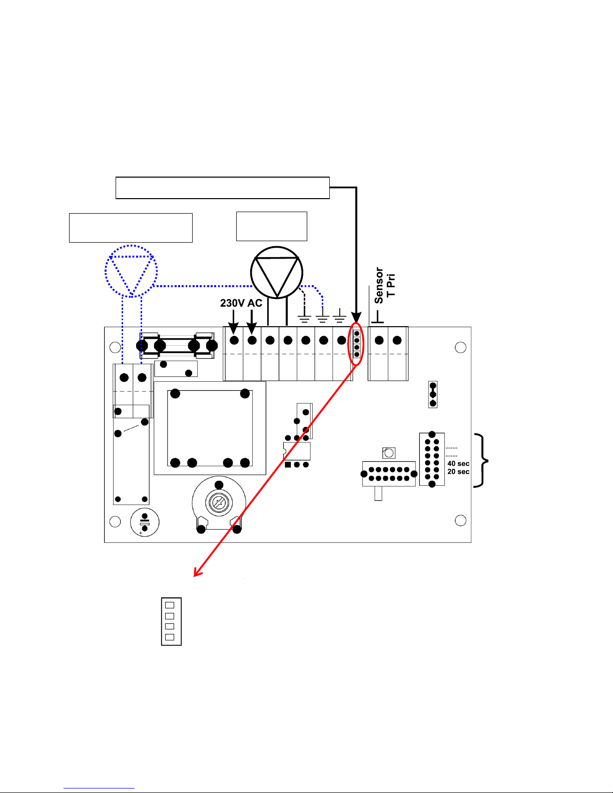
Electrical circuit diagram
Plug for volume flow sensor VFS
Fuse 3.15A
quick-acting
Note the plug layout:
brown
green
white
yellow
Optional:
Circulation pump
Primary
pump
Selection switch
Runtime
circulation pump

15
Controller settings
Operation of the controller has been kept as simple as possible, so that it can also be operated by inexperienced users.
Manual-automatic changeover switch
Switch position
OFF (AUS)
The pump is permanently switched off.
AUTO
The pump runs according to the controller settings.
ON (EIN)
The pump is switched on continuously at full speed, independent of
the control temperature.
Selection switch runtime circulation pump
The selection occurs by means of a slide switch on the right border of the board. There is no
access possible to the slide switch from outside.
Switch position
Runtime
PWM.I
Without function
PWM.N
Without function
PuT.2
40 seconds
PuT.1
20 seconds
LED display
Pump start-up
Manual-automatic
Changeover switch
Temperature selection

16
Technical data
Rated power
70 kW
Min. flow
2 l /min
Max. flow for 65°C tank and 45°C outlet temperature
30 l/min
Max. permissible flow
40 l/min
Max. operating pressure primary side (tank water)
4 bar
Max. operating pressure secondary side (cold water)
8 bar
Max. permissible water hammer pressure
15 bar
Rated temperatures primary flow / return
65 / 20 °C
Rated temperatures secondary flow / return
45 / 10 °C
Max. operating temperature primary/secondary
90 °C
Pressure loss secondary side (Kv value)
2.60 m³/h
Connection thread primary and secondary
G ¾” external thread
Materials (corresponding to DVGW/W270):
Fittings
Brass CW617N
Heat exchanger
Stainless steel 1.4401, copper
soldered
Pipes
Copper 99.96%
Seal material
PTFE, EPDM, Klingersil C-4324
Pump primary circuit
WILO ST20/7-3C
Volume flow sensor
Grundfos VFS 2-40
Primary sensor
PT1000
Controller
FWR21-FRISTAR
Indication referring to COMMISSION REGULATION (EU) No 622/2012:
The benchmark for the most efficient circulators is EEI ≤ 0.20.
Transmission power with different flow and outlet temperatures:
Pump mode
Buffer
flow [°C]
Return
[°C]
Cold water
supply [°C]
Hot water
outlet [°C]
Power
[kW]
Flow [l/h]
100%
59.3
25.0
10.3
45.0
68.7
1700
100%
55.4
27.0
10.3
45.0
56.5
1400
100%
50.3
33.2
10.3
45.4
34.7
850
100%
50.2
25.2
10.3
40.3
50.6
1450

17
Pressure loss characteristic curve plate heat exchanger:
Pressure loss characteristic pump
(1 m WC = 98 mbar)
Flow [l/min]
Pressure [mbar]
Durchfluss [m³/h]
Pressure [m WC]
Flow [m³/h]
0
100
200
300
400
500
600
0 5 10 15 20 25 30 35 40 45 50

18
Plate heat exchanger corrosion resistance
The corrosion behaviour of stainless steel and copper solder must be considered.
Water containing
material
Chloride
See diagram
Iron
< 0.2 mg/l
Manganese
< 0.1 mg/l
Ammonia
< 2 mg/l
pH value
7 - 9
Electrical conductivity
10 – 500 µS/cm
Free carbonic acid
< 20 mg/l
Nitrate
< 100 mg/l
Sulphate
< 100 mg/l
Saturation index SI
-0.2 < 0 < +0.2
Total hardness
6 – 15 °dH
Filterable substances
< 30 mg/l
Free chlorine
< 0.5 mg/l
Hydrogen sulphide
< 0.05 mg/l
Hydrogen carbonate
< 300 mg/l
Hydrogen car-
bonate/sulphate
> 1 mg/l
Sulphide
< 1mg/l
Nitrite
< 0.1 mg/l
We reserve the right to make technical changes. © 2014
Temperature [°C]

EC- DECLARATION OF CONFORMITY
Document- Nr. / Date:
TA12025 / 19.11.2012
Company / Manufacturer:
Technische Alternative elektronische SteuerungsgerätegesmbH.
Address:
A- 3872 Amaliendorf, Langestraße 124
This declaration of conformity is issued under the sole responsibility of the manufacturer.
Product name:
FRISTAR
Product brand:
Technische Alternative GmbH.
Product description:
Fresh water station
The object of the declaration described above is in conformity with Directives:
2006/95/EG
Low voltage standard
2004/108/EG
Electromagnetic compatibility
2011/65/EU
RoHS Restriction of the use of certain hazardous substances
2006/42/EG
Machinery Directive (WILO pump)
Employed standards:
EN 60730-1: 2011
Automatic electrical controls for household and similar use –
Part 1: General requirements
EN 61000-6-3: 2007
+A1: 2011
Electromagnetic compatibility (EMC) - Part 6-3: Generic standards - Emission standard for residential, commercial and light-industrial environments
EN 61000-6-2: 2005
Electromagnetic compatibility (EMC) - Part 6-2: Generic standards - Immunity for industrial environments
For WILO pump: EN 809, EN ISO 12100-1, EN ISO 12100-2, EN ISO 14121-1, EN 60335-1, EN
60335-2-51, EN 61800-3, EN 61800-5-1
Position of CE - label: On packaging, manual and type label
Issuer:
Technische Alternative elektronische SteuerungsgerätegesmbH.
A- 3872 Amaliendorf, Langestraße 124
This declaration is submitted by
Kurt Fichtenbauer, General manager,
19.11.2012
This declaration certifies the agreement with the named standards, contains however no warranty of
characteristics.
The security advices of included product documents are to be considered.

Guarantee conditions
Note: The following guarantee conditions do not in any way limit the legal right to a guarantee, rather
expand your rights as a consumer.
1. The company Technische Alternative elektronische Steuerungsgerätegesellschaft m. b. H.
provides a two-year guarantee from the date of purchase by the end consumer for all the devices and parts which it sells. Defects must be reported immediately upon detection and within
the guarantee period. Technical support knows the correct solution for nearly all problems. In
this respect, contacting us immediately will help to avoid unnecessary expense or effort in
troubleshooting.
2. The guarantee includes the free of charge repair (but not the cost of on-site fault-finding, removal, refitting and shipping) of operational and material defects which impair operation. In the
event that a repair is not economically worthwhile according to the assessment of Technische
Alternative, the goods will be replaced.
3. Not included is damage resulting from the effects of overvoltages or abnormal ambient conditions. Likewise, no guarantee liability can be accepted if the device defect is due to: transport
damage for which we are not responsible, incorrect installation and assembly, incorrect use,
non-observance of operating and installation instructions or incorrect maintenance.
4. The guarantee claim will expire if repairs or actions are carried out by persons who are not authorised to do so or have not been so authorised by us or if our devices are operated with
spare, supplementary or accessory parts which are not considered to be original parts.
5. The defective parts must be sent to our factory with an enclosed copy of the proof of purchase
and a precise description of the defect. Processing is accelerated if an RMA number is applied
for via our home page www.ta.co.at. A prior clarification of the defect with our technical support is necessary.
6. Services provided under guarantee result neither in an extension of the guarantee period nor
in a resetting of the guarantee period. The guarantee period for fitted parts ends with the
guarantee period of the whole device.
7. Extended or other claims, especially those for compensation for damage other than to the device itself are, insofar as a liability is not legally required, excluded.
Legal notice
These assembly and operating instructions are protected by copyright.
Use outside the copyright requires the consent of the company Technische Alternative elektronische
Steuerungsgerätegesellschaft m. b. H.. This applies in particular to reproductions, translations and
electronic media.
elektronische Steuerungsgerätegesellschaft m. b. H.
A-3872 Amaliendorf Langestraße 124
Tel +43 (0)2862 53635 Fax +43 (0)2862 53635 7
E-Mail: mail@ta.co.at --- www.ta.co.at --- © 2014
 Loading...