

Page 1
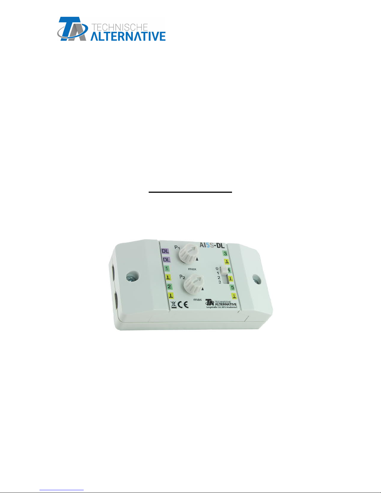
AI5S-DL
INPUT EXPANSION
Version 1.02
Mode of operation
Programming
englishManual Version 1.02
Page 2
2
The AI5S-DL (= "Analogue Input", DIP switch) translates signals for the data link (DL bus).
These can originate from the two potentiometers, the DIP switch (4 positions, values 0-3) or
from up to 5 difference external 0-10 V sources. It is recommended, that the 0-10V sensors
that are being read out be connected to the same controller as the AI5S-DL itself.
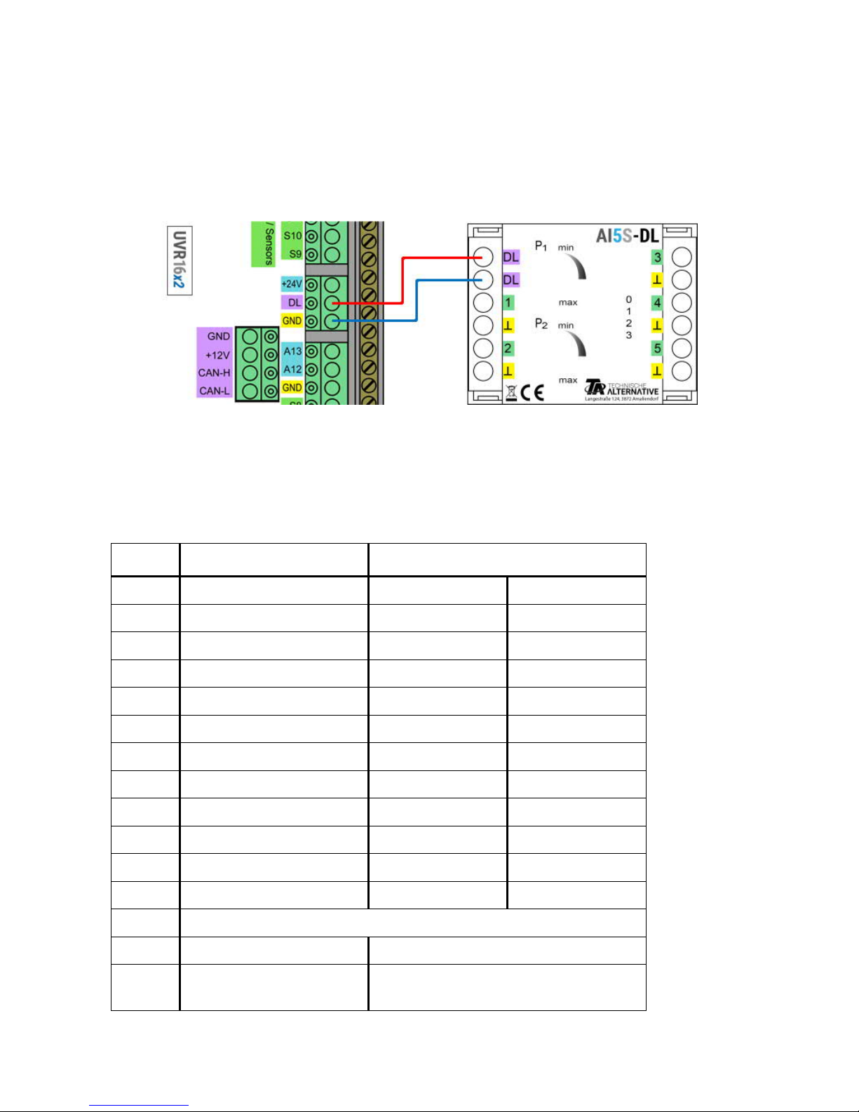
Electrical Connection
Example: Connection to a UVR16x2 controller
The principles of DL bus cabling are described extensively in the installation instructions for
the freely programmable controllers. The polarity of the data link is interchangeable.
Index
The AI5S-DL forwards values to the data link via 12 indices. These are either measured via
the inputs or set on the device with the potentiometers or manually with the DIP switch.
*Buttons only on model AI5T-DL.
Index Unit Source
1 Volt External sensor Channel 1
2 Volt External sensor Channel 2
3 Volt External sensor Channel 3
4 Volt External sensor Channel 4
5 Volt External sensor Channel 5
6 Percent Potentiometer P1
7 Percent Potentiometer P2
8 Dimensionless DIP-switch 0-3
9 Dimensionless Button* -
10 Dimensionless Button* -
11 Dimensionless/Flip-Flop Button* -
12 Dimensionless/Flip-Flop Button* -
13 Not relevant for AI5-DL
14 Dimensionless Serial number of the module
15 Dimensionless Software version (without decimal
points)
Page 3
3
DL address
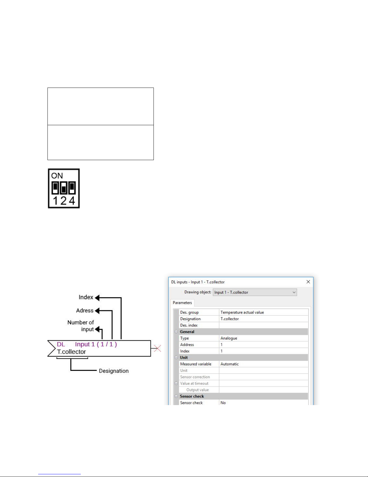
The AI5-DL has a default address of 1. This address can be changed using the DIP switches
in the device. The final address is made up of the default 1 and the sum of the DIP switches
that are switched to „ON“.
Example
Position of DIP switches acc. to example.
Programming in TAPPS2
In the following examples, the default DL bus address of 1 is used.
The most important settings can be found under General. Here state the DL bus address
(WE = 1) set on the AI5-DL as well as the index of the desired value.
Desired address 6
Default setting 1
Dip-switches 1 and 4 + 5
Sum = Address = 6
DIP switches 1 and 4 must be
set to ON.
Page 4
4
If the Measured variable is set to Automatic, it is not possible to perform any further settings
under Unit. However, other values can be simulated by changing the measured variables: if,
for example, the measured variable "Temperature" is assigned to one of the potentiometers
(indices 6 and 7), this can be used to simulate a temperature for a controller for further cal-
culations.
The table found under Index (page 2) provides information about which index outputs
which value with which measured variable.
On this model, Indices 9-12 are surplus to requirements, as the device does not have any
buttons (see AI5T-DL).
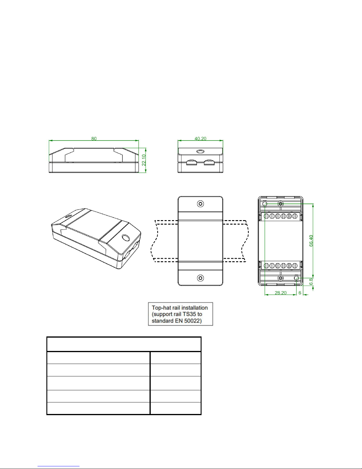
Dimensions in mm
Subject to technical modifications. ©2018
Technical Data
DL bus load 15%
IP rating IP40
Terminal
max. 1,5 mm
2
Max. ambient temperature 45 °C
Input voltage range 0-10 V
 Loading...