

Page 1
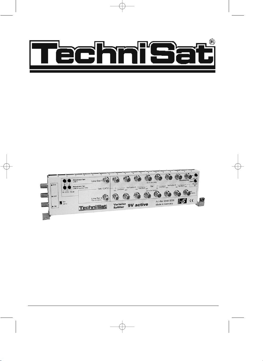
Distributor 9V active
Installation instructions
1017/01
mont9v_1_englisch_1.qxd 26.10.01 09:35 Seite 1
Page 2

1. General
The 9V active distributor has been developed for the GigaSwitch series 11/20. Installation
of the 9V active makes it possible to distribute satellite signals, in combination with terrestrial resp. cable signals, to up to 240 user.
In order to ensure optimum signal quality for all user, installation should be carried out only
by trained personnel using selective measuring instruments!
2 Security notes
For your own safety, you should read the notes on safety precautions carefully before installing the distributor. The manufacturer cannot be held responsible for damage caused by nonadherence to the safety precautions, or by inappropriate handling.
> The components must be mounted in a dry room, on flat surfaces that are not easily
inflammable.
> The ventilation slots of the components may not be covered.
> Install the unit while it is disconnected from the power supply.
> The Multiswitch must be connected to earth.
> The antenna unit must be protected against lightning strikes in accordance with local
regulations.
> All relevant European norms and VDE regulations with regard to the maintenance of
electrical safety must be complied with.
> Any specific national restrictions on the installation of broadcast receiving equipment
must be complied with.
> Do not open the equipment housing under any circumstances, as the danger of recei-
ving an electrical shock exists!!! If it is ever necessary to open the housing, this only
should be carried out by trained personnel.
In the following cases, you should disconnect the unit from the mains power, and obtain
assistance from a suitably qualified person:
> if the unit has been subjected to extreme humidity, or if liquid has entered the unit,
> if the equipment malfunctions,
> if the exterior of the unit has been severely damaged.
3 Description of the connections and installation instructions for
the 9V active distributor
Inputs
LNB In
Connect the LNB inputs of the distributor with the LNB outputs of the LNB unit(s), taking into
account the relevant polarisation planes and frequency bands. Note the maximum input
levels specified in the Technical Data section of this manual.
DC electrical power supply
The LNB inputs of the 9V active distributor take over the supply of power to the LNBs.
The power is supplied from the GigaSwitch 11/20G connected at Line 1 and Line 3 out-
puts of the 9V active.
2
mont9v_1_englisch_1.qxd 26.10.01 09:35 Seite 2
Page 3
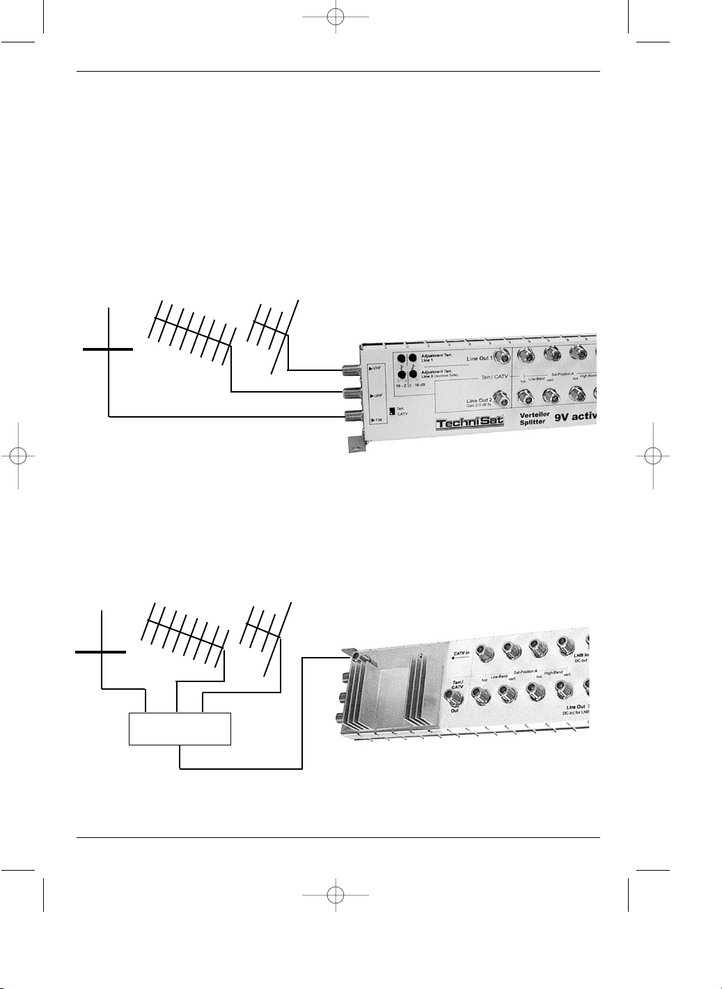
Terrestrial/CATV
The 9V active distributor permits optional to feed in terrestrial signals via the selective
inputs “VHF, UHF and FM” or to feed in broadband signals via the “CATV In” input. Set
the function selector switch “Terr./CATV” to the appropriate application as required. Open
terrestrial inputs should be terminated by means of a 75 Ohm terminating resistor. Please
note the specified maximum input levels set out in the Technical Data section of this
manual.
Following possibilities of connections exist:
1. Direct connection of the antennas
2. Combining terrestrial antennas / feeding with broadband signals
3
FM UHF VHF
FM UHF VHF
mont9v_1_englisch_1.qxd 26.10.01 09:35 Seite 3
Page 4
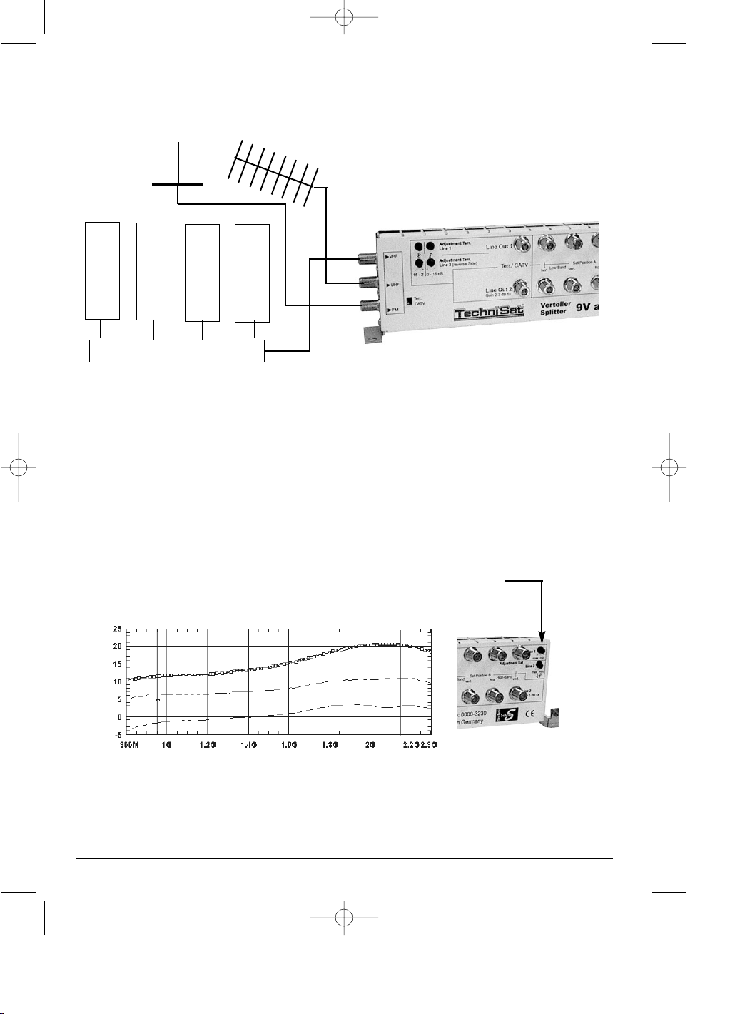
3. Analogue and digital Satellite -TV processing for SMATV systems + terrestrial
antennas
Outputs Line 1 and 3
Satellite
The Line 1 and Line 3 outputs are designed to provide the signal to more distant trunks.
For these outputs, it is possible to regulate both gain and slope in combination, in accordance with the appropriate cable length. The maximum gain is 20dB, the maximum slope equalization is -10dB at 950 MHz.
When setting and adjusting the system, please note the specified maximum output levels set
out in the Technical Data section of this manual.
Gain graph for outputs Line 1 and Line 3 (Satellite range)
DC-Power supply
The satellite outputs Line 1 and Line 3 are fed by the GigaSwitch 11/20G connected to
the system. The current available at these outputs is fed to the inputs of the LNBs, and thus
serves to provide current to the LNBs.
4
FM UHF
Gain and slope are set appropriately syn-
chronous to the cable length
mont9v_1_englisch_1.qxd 26.10.01 09:35 Seite 4
Page 5

Terrestrial/CATV
This input provides the feed for whatever terrestrial signal sources are connected to the
system. The terrestrial signal can be separately adjusted in terms of gain (0 to 16dB) and
slope (2 to 16dB).
When setting and adjusting the system, please note the specified maximum output levels set
out in the Technical Data section of this manual.
Gain graph for the Line 1 and Line 3 outputs (terrestrial)
Outputs Line 2
Satellite
The Line 2 outputs have been designed to feed the signal to the local GigaSwitch 11/20G.
The gain level is fixed, and set at 5dB.
DC Power supply
The Line 2 satellite outputs are fed via the GigaSwitch 11/20G connected to the
system.Thus, the GigaSwitch 11/20G connected to the Line 2 output provides the power
supply for the 9V active distributor.
Terrestrial/CATV
Any terrestrial signals are available at this connection, depending on sources selected. Gain
is fixed, and is set in the range 2 to 3dB.
Gain graph for Line 2 outputs
5
Attenuation and slope can be
adjusted independently
full gain, no slope
minimal gain, no slope
mont9v_1_englisch_1.qxd 26.10.01 09:35 Seite 5
Page 6
6
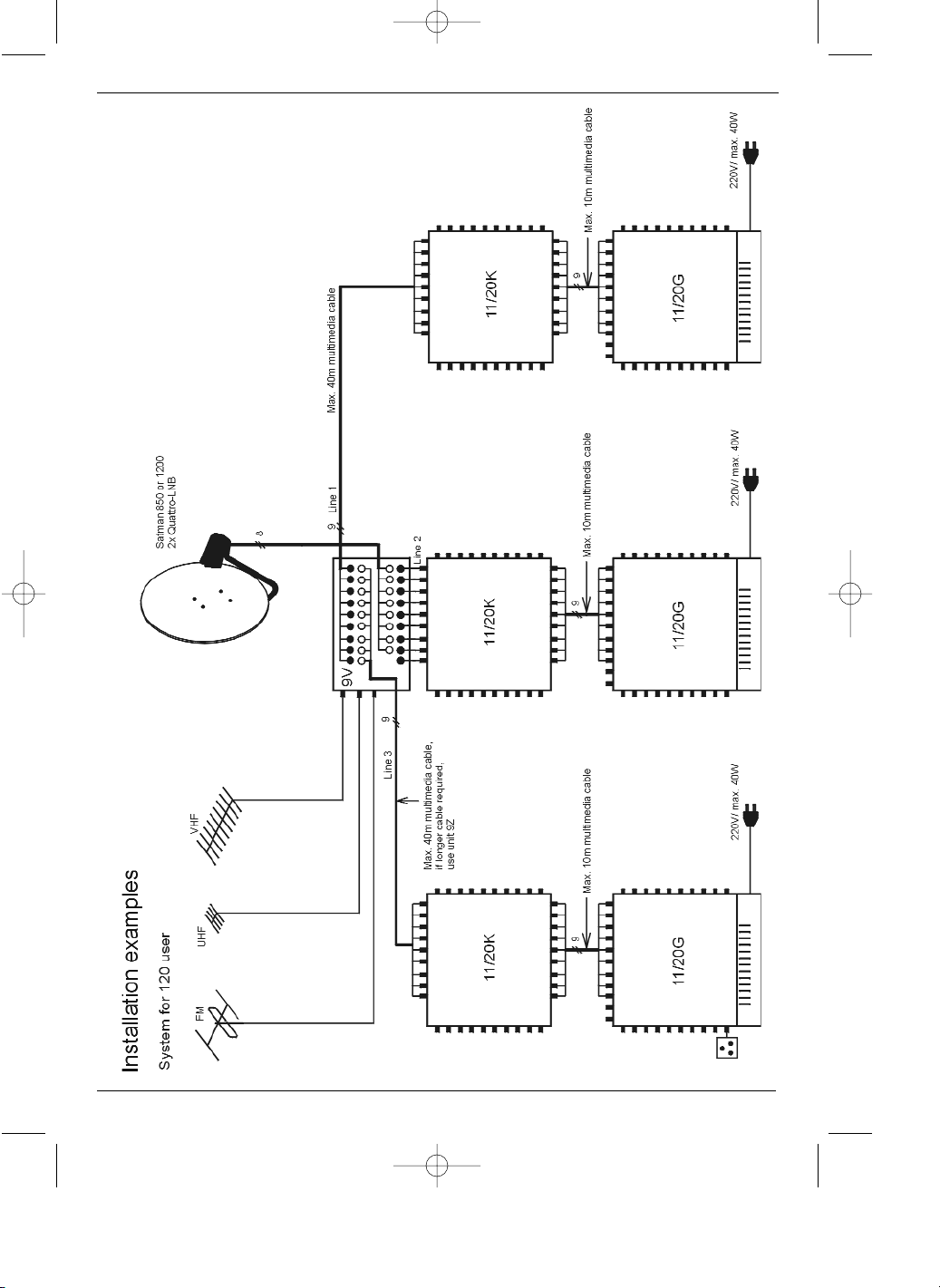
4 Configuration examples
mont9v_1_englisch_1.qxd 26.10.01 09:35 Seite 6
Page 7

7
mont9v_1_englisch_1.qxd 26.10.01 09:35 Seite 7
Page 8

8
mont9v_1_englisch_1.qxd 26.10.01 09:35 Seite 8
 Loading...