


Special Documentation
Proline Promass 300
EtherNet/IP
Web Server
SD02129O/06/EN/01.17
Valid as of version 01.00.zz (Device rmware)
71382455
MANUAL

Important
All information and technical specications in this documentation have been carefully checked and compiled by
the author. However, we cannot completely exclude the possibility of errors. TechnipFMC is always grateful to be
informed of any errors. Contact us on the website.
Smith Meter® is a registered trademark of TechnipFMC.
Technical Support
Contact Information:
Field Service Response Center
24/7 Technical Support/Schedule a Technician: 1-844-798-3819
System Installation Supervision, Start-Up, and Commissioning Services Available
Customer Support
Contact Information:
Customer Service
TechnipFMC
1602 Wagner Avenue
Erie, Pennsylvania 16510 USA
P: +1 814 898-5000
F: +1 814 899-8927
measurement.solutions@TechnipFMC.com
TechnipFMC.com
Literature Library:
http://fmctechnologies.com/en/MeasurementSolutions/OnlineServices.aspx

Proline Promass 300 EtherNet/IP Table of contents
Table of contents
1 About this document ................ 4
1.1 Document function ..................... 4
1.2 Target group .......................... 4
1.3 Using this document .................... 4
1.4 Symbols used .......................... 5
2 Basic safety instructions ............ 6
2.1 Requirements for personnel ............... 6
2.2 Designated use ........................ 6
2.3 Occupational safety ..................... 6
2.4 Operational safety ...................... 6
2.5 Product safety ......................... 6
2.6 IT security ............................ 7
2.7 Device-specific IT security ................. 7
3 Product features and availability ..... 8
3.1 Product features ....................... 8
3.2 Availability ........................... 8
3.3 Identification in the measuring device ....... 8
4 Commissioning ..................... 9
4.1 Prerequisites - computer ................. 9
4.2 Prerequisites - measuring device .......... 15
4.3 Connecting the computer to the measuring
device .............................. 16
4.4 Establishing a connection to the Web
server .............................. 19
4.5 Setting the IP address .................. 21
4.6 Overview of the Web server parameters ..... 21
5 Operation options ................. 24
5.1 Logging on .......................... 25
5.2 User interface ........................ 26
5.3 Logging out .......................... 27
5.4 Addressing Ethernet-based fieldbuses ...... 27
6 Diagnostics and troubleshooting ... 30
6.1 General Web server troubleshooting ........ 30
6.2 Diagnostic information in the Web browser .. 31
6.3 Diagnostic information in the measuring
device .............................. 33
6.4 Checking the network connection .......... 33
7 Technical data .................... 34
3

About this document Proline Promass 300 EtherNet/IP
1 About this document
1.1 Document function
This manual is a Special Documentation; it does not replace the Operating Instructions
pertaining to the device. It serves as a reference for using the Web server integrated in the
measuring device.
1.2 Target group
The document is aimed at specialists who work with the device over the entire life cycle
and perform specific configurations.
1.3 Using this document
1.3.1 Information on the document structure
This Special Documentation contains a range of information, including:
• Prerequisites for use on the computer and measuring device
• Connection of the computer via the service interface, WLAN interface or Ethernet-based
fieldbus
• Configuration of the communication interface
• Establishing a connection
• Diagnostics and troubleshooting
The information and safety instructions in the Operating Instructions pertaining to
the measuring device must always be observed → 4.
1.3.2 Device documentation
The Technical Documentation for the measuring device is available:
• On the CD-ROM supplied with the measuring device (depending on the device version,
the CD-ROM might not be part of the delivery!)
• Via the W@M Device Viewer: enter the serial number from the nameplate
(www.endress.com/deviceviewer)
• Via the Endress+Hauser Operations App: enter the serial number from the nameplate or
scan the 2-D matrix code (QR code) on the nameplate.
Technical documentation can also be downloaded from the Download Area of the
Endress+Hauser web site: www.endress.com → Download. However this technical
documentation applies to a particular instrument family and is not assigned to a
specific measuring device.
4

Proline Promass 300 EtherNet/IP About this document
DANGER
WARNING
CAUTION
NOTICE
A
1.
1.
1.4 Symbols used
1.4.1 Safety symbols
Symbol Meaning
DANGER!
This symbol alerts you to a dangerous situation. Failure to avoid this situation will
result in serious or fatal injury.
WARNING!
This symbol alerts you to a dangerous situation. Failure to avoid this situation can
result in serious or fatal injury.
CAUTION!
This symbol alerts you to a dangerous situation. Failure to avoid this situation can
result in minor or medium injury.
NOTE!
This symbol contains information on procedures and other facts which do not result in
personal injury.
1.4.2 Symbols for certain types of information
Symbol Meaning
Permitted
Indicates procedures, processes or actions that are allowed.
Forbidden
Indicates procedures, processes or actions that are forbidden.
Tip
Indicates additional information.
Reference to documentation
Reference to page
Reference to graphic
Notice or individual step to be observed
, 2., 3.… Series of steps
Result of a step
1.4.3 Symbols in graphics
Symbol Meaning
1, 2, 3,... Item numbers
, 2., 3.… Series of steps
5

Basic safety instructions Proline Promass 300 EtherNet/IP
2 Basic safety instructions
2.1 Requirements for personnel
Personnel involved in installation, commissioning, diagnostics and maintenance must
meet the following requirements:
Trained, qualified specialists must have a relevant qualification for this specific function
‣
and task
Are authorized by the plant owner/operator
‣
Are familiar with federal/national regulations
‣
Before starting work, read and understand the instructions in the manual and
‣
supplementary documentation as well as the certificates (depending on the
application)
Follow instructions and comply with basic conditions
‣
Operating personnel must meet the following requirements:
Be instructed and authorized by the plant operator with regard to the requirements of
‣
the task
Follow the instructions in this manual
‣
2.2 Designated use
The designated use of the measuring device is described in the Operating Instructions
pertaining to the device → 4.
2.3 Occupational safety
For work on and with the device:
Wear the required personal protective equipment according to federal/national
‣
regulations.
If working on and with the device with wet hands:
It is recommended to wear gloves on account of the higher risk of electric shock.
‣
2.4 Operational safety
Risk of injury!
Operate the device in proper technical condition and fail-safe condition only.
‣
The operator is responsible for interference-free operation of the device.
‣
Modifications to the device
Unauthorized modifications to the device are not permitted and can lead to unforeseeable
dangers.
If, despite this, modifications are required, consult with Endress+Hauser.
‣
2.5 Product safety
This device is designed in accordance with good engineering practice to meet state-of-theart safety requirements, has been tested, and left the factory in a condition in which it is
safe to operate.
6

Proline Promass 300 EtherNet/IP Basic safety instructions
It meets general safety standards and legal requirements. It also complies with the EC
directives listed in the device-specific EC Declaration of Conformity. Endress+Hauser
confirms this by affixing the CE mark to the device.
2.6 IT security
We only provide a warranty if the device is installed and used as described in the
Operating Instructions. The device is equipped with security mechanisms to protect it
against any inadvertent changes to the device settings.
IT security measures in line with operators' security standards and designed to provide
additional protection for the device and device data transfer must be implemented by the
operators themselves.
2.7 Device-specific IT security
The device offers a range of specific functions to support protective measures on the
operator's side. These functions can be configured by the user and guarantee greater inoperation safety if used correctly.
2.7.1 Access via CDI-RJ45 service interface
The device can be connected to a network via the CDI-RJ45 service interface. Devicespecific functions guarantee the secure operation of the device in a network.
It is advisable to take relevant security concepts into consideration, such as those issued by
the Federal Office for Information Security. This includes organizational security measures
such as the assignment of access authorization as well as technical measures such as
network segmentation.
The device can be integrated in a ring topology. The device is integrated via the
terminal connection for signal transmission (output 1) and the connection to the
service interface (CDI-RJ45) .
7

Product features and availability Proline Promass 300 EtherNet/IP
Service Int. (CDI)
IP 192.168.1.212
1
2
3 Product features and availability
3.1 Product features
Thanks to the integrated Web server, the device can be operated and configured via a Web
browser and via a service interface (CDI-RJ45) or via a WLAN interface. The structure of
the operating menu is the same as for the local display. In addition to the measured values,
status information on the device is also displayed and allows the user to monitor the status
of the device. Furthermore the device data can be managed and the network parameters
can be configured.
A device that has a WLAN interface (can be ordered as an option) is required for the
WLAN connection: order code for "Display; operation", option G "4-line, illuminated; touch
control + WLAN". The device acts as an Access Point and enables communication by
computer or a mobile handheld terminal.
3.2 Availability
The integrated Web server is a standard feature. It does not need to be ordered for the
device ex works as it is provided as standard when the device is delivered to the customer.
No particular measures are required to put the feature into operation.
3.3 Identification in the measuring device
An adhesive label on the inside of the electronics compartment cover or the connection
compartment describes all the available hardware components, and their functions, for the
measuring device. The service interface (CDI-RJ45) has the following identification:
A0030874
1 Example of the CDI-RJ45 service interface
1 Symbol for service interface
2 Information on the default setting for the WLAN IP address
8

Proline Promass 300 EtherNet/IP Commissioning
4 Commissioning
Establishing a connection to the integrated Web server
1. Configure the computer → 9.
2. Check the settings on the measuring device and change them if necessary → 15.
3. Connect the measuring device to the computer .
4. Establish a connection to the Web server → 19.
5. Start the Web browser and access the operating menu → 20.
The measuring device can be operated via the Web server.
4.1 Prerequisites - computer
4.1.1 Hardware
Hardware Interface
CDI-RJ45 WLAN
Interface The computer must have an RJ45
interface.
Connection Standard Ethernet cable with RJ45
connector.
Screen Recommended size: ≥12" (depends on the screen resolution)
The operating unit must have a
WLAN interface.
Connection via Wireless LAN.
4.1.2 Software
Software Interface
CDI-RJ45 WLAN
Recommended operating
systems
Web browsers supported • Microsoft Internet Explorer 8 or higher
• Microsoft Windows 7 or higher.
• Mobile operating systems:
– iOS
– Android
Microsoft Windows XP is supported.
• Microsoft Edge
• Mozilla Firefox
• Google Chrome
• Safari
4.1.3 Configuring the computer
User rights Appropriate user rights (e.g. administrator rights) for TCP/IP and proxy server
settings are necessary (for adjusting the IP address, subnet mask etc.).
Proxy server settings of the
Web browser
The Web browser setting Use a Proxy Server for Your LAN must be
deselected .
9

Commissioning Proline Promass 300 EtherNet/IP
JavaScript JavaScript must be enabled.
If JavaScript cannot be enabled:
enter http://192.168.1.212/basic.html in the address line of the Web
browser. A fully functional but simplified version of the operating menu
structure starts in the Web browser.
When installing a new firmware version: To enable correct data display,
clear the temporary memory (cache) of the Web browser under Internet
options.
Network connections Only the active network connections to the measuring device should be used.
Switch off all other network connections such as WLAN.
10

Proline Promass 300 EtherNet/IP Commissioning
adapter
Configuring IP settings for Windows
• To configure the IP settings, appropriate user rights (e.g. administrator rights) are
required for the computer.
• Before configuring the IP settings, close all the windows of the Web browser.
1. Click Start (Windows icon).
The Start menu appears.
2. In the Start menu, select Control Panel.
This opens a new window with the control panel elements.
3. Enter the term "adapter" in the search field.
The Network and Sharing Center is listed in the search results.
4. Select the Network Connections option under Network and Sharing Center.
This opens a new window with the network connections.
5. In this window, select the Local Area Connection (LAN).
A0024277
A0024293
11
Commissioning Proline Promass 300 EtherNet/IP
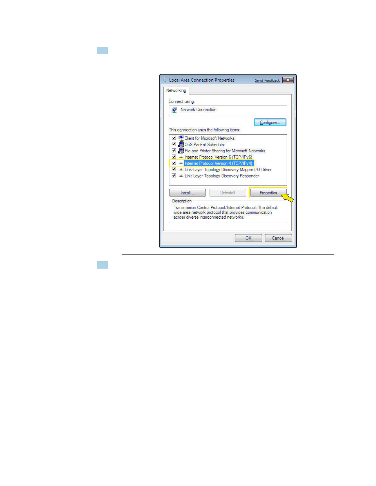
6. Right-click to open the picklist and select Properties.
The Local Area Connection Properties dialog box opens.
7. Select the Internet Protocol Version 4 (TCP/IPv4) item.
A0024300
12

Proline Promass 300 EtherNet/IP Commissioning
8. Click the Properties button.
The Internet Protocol Version 4 (TCP/IPv4) Properties window opens.
A0024309
9. In the General tab, select the Use the Following IP Address option.
10. Enter the IP address, subnet mask and default gateway as indicated in the following
table and then click Ok to confirm.
Standard settings for IP address, subnet mask and default gateway
IP address 192.168.1.XXX
For XXX all numerical sequences except: 0, 212 and 255 → e.g.
192.168.1.213
Subnet mask 255.255.255.0
Default gateway 192.168.1.212 or leave cells empty
The standard settings correspond to those for private networks. In the case of
Ethernet-based networks, the settings can deviate from these standard settings and
must be changed if necessary.
13
Commissioning Proline Promass 300 EtherNet/IP
Changing the proxy server settings
To establish communication, the proxy server setting Use a Proxy Server for Your LAN must
be deselected for the Web browser.
To change the proxy server setting, appropriate user rights (e.g. administrator rights)
are required for the computer.
Changing the proxy server settings taking Internet Explorer as the sample browser
1. Open the Web browser.
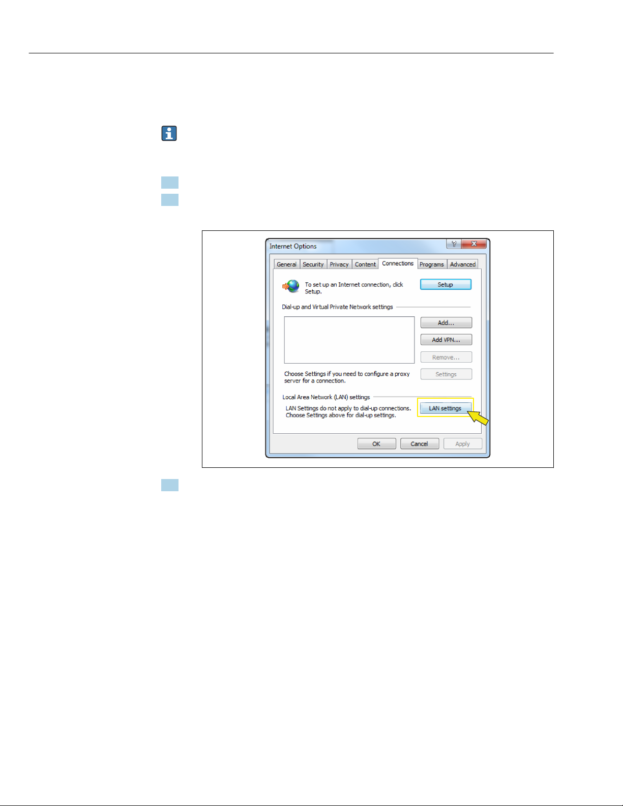
2. In the Options menu, select the Internet Options item.
This opens a new window with the Internet options.
3. Select the Connections tab.
A0024310
14

Proline Promass 300 EtherNet/IP Commissioning
4. Under Local Area Network Settings click the LAN Settings button.
This opens a new window with the Local Area Network Settings.
A0024311
5. Deselect the Use a Proxy Server for Your LAN checkbox and then click Ok to confirm.
4.2 Prerequisites - measuring device
4.2.1 Enabling the Web server
The Web server must be enabled in the measuring device (factory setting).
If the Web server is disabled it be enabled again via the Web server functionality
parameter (→ 23). To do so, users can choose from the following operation options:
• Local display
• Operating tool e.g. FieldCare, DeviceCare, AMS Device Manager , SIMATIC PDM
4.2.2 Determining the IP address of the measuring device
The IP address of the measuring device is required to establish communication between
the measuring device (Web server) and a computer (client). The IP address used depends
on the setting of the DIP switches or on the system settings.
The IP address can be assigned to the measuring device in a variety of ways:
• Dynamic Host Configuration Protocol (DHCP), factory setting:
The IP address is automatically assigned to the measuring device by the automation
system (DHCP server).
• Hardware addressing:
The IP address is set via DIP switches
• Software addressing:
The IP address is entered via the IP address parameter (→ 23)
• DIP switch for "Default Ethernet Network Settings":
For establishing the network connection via the service interface (CDI-RJ45). The fixed
IP address 192.168.1.212 is used .
15

Commissioning Proline Promass 300 EtherNet/IP
IP address
assigned or
specified via:
Dynamic Host
Configuration Protocol
(DHCP), factory setting
Hardware addressing of
the IP address via DIP
switches
Software addressing of
the IP address via the IP
address parameter
DIP switch for "Default
Ethernet Network
Settings", use the fixed IP
address: 192.168.1.212
Determine IP address settings via parameters or DIP switches
Local display
(if available)
Operating tool e.g.
FieldCare, DeviceCare,
AMS Device Manager,
SIMATIC PDM
DIP switches in
electronics compartment
Position of the DIP switches → 8
Using the local display or an operating tool
The IP address parameter can be used to determine the IP address via the local display or
via an operating tool e.g. FieldCare, DeviceCare, AMS Device Manager, SIMATIC PDM.
4.3 Connecting the computer to the measuring device
The measuring device can be connected to the computer via:
• Service interface (CDI-RJ45)
• WLAN interface
• Ethernet-based fieldbuses
4.3.1 Via service interface (CDI-RJ45)
Preparing the measuring device
1. Depending on the housing version:
Release the securing clamp or securing screw of the housing cover.
2. Depending on the housing version:
Unscrew or open the housing cover.
3. The location of the connection socket depends on the measuring device and the
communication protocol:
Connect the computer to the RJ45 connector via the standard Ethernet connecting
cable → 8.
16
Proline Promass 300 EtherNet/IP Commissioning
Configuring the Internet protocol of the computer
NOTICE
Risk of electric shock! Components carry dangerous voltages!
Never open the measuring device while it is connected to the supply voltage.
‣
The information and safety instructions in the Operating Instructions pertaining to the
‣
measuring device must always be observed → 4.
The IP address can be assigned to the measuring device in a variety of ways:
• Dynamic Host Configuration Protocol (DHCP), factory setting:
The IP address is automatically assigned to the measuring device by the automation
system (DHCP server).
• Hardware addressing:
The IP address is set via DIP switches .
• Software addressing:
The IP address is entered via the IP address parameter (→ 23) .
• DIP switch for "Default IP address":
To establish the network connection via the service interface (CDI-RJ45): the fixed IP
address 192.168.1.212 is used .
The measuring device works with the Dynamic Host Configuration Protocol (DHCP), on
leaving the factory, i.e. the IP address of the measuring device is automatically assigned by
the automation system (DHCP server).
To establish a network connection via the service interface (CDI-RJ45): the "Default IP
address" DIP switch must be set to ON. The measuring device then has the fixed IP address:
192.168.1.212. This address can now be used to establish the network connection.
If the IP address of the measuring device is assigned via hardware or software
addressing and the IP address is known, the network connection can also be
established directly via the Ethernet network → 16.
1. Via DIP switch 2, activate the default IP address 192.168.1.212: .
2. Switch on the measuring device.
3. Connect to the computer using a cable → 8.
4. If a 2nd network card is not used, close all the applications on the notebook.
Applications requiring Internet or a network, such as e-mail, SAP applications,
Internet or Windows Explorer.
5. Close any open Internet browsers.
6. Configure the properties of the Internet protocol (TCP/IP) as defined in the table:
IP address 192.168.1.XXX; for XXX all numerical sequences except: 0, 212 and 255 → e.g.
192.168.1.213
Subnet mask 255.255.255.0
Default gateway 192.168.1.212 or leave cells empty
4.3.2 Via WLAN interface
Configuring the Internet protocol of the mobile terminal
NOTICE
If the WLAN connection is lost during the configuration, settings made may be lost.
Make sure that the WLAN connection is not disconnected while configuring the device.
‣
17

Commissioning Proline Promass 300 EtherNet/IP
NOTICE
In principle, avoid simultaneous access to the measuring device via the service
interface (CDI-RJ45) and the WLAN interface from the same mobile terminal. This
could cause a network conflict.
Only activate one service interface (CDI-RJ45 service interface or WLAN interface).
‣
If simultaneous communication is necessary: configure different IP address ranges, e.g.
‣
192.168.0.1 (WLAN interface) and 192.168.1.212 (CDI-RJ45 service interface).
Preparing the mobile terminal
Enable WLAN reception on the mobile terminal.
‣
Establishing a connection from the mobile terminal to the measuring device
1. In the WLAN settings of the mobile terminal:
Select the measuring device using the SSID (e.g. EH_Promass_300_A802000).
2. If necessary, select the WPA2 encryption method.
3. Enter the password: serial number of the measuring device ex-works (e.g.
L100A802000).
LED on display module flashes: it is now possible to operate the measuring device
with the Web browser.
The serial number can be found on the nameplate.
To ensure the safe and swift assignment of the WLAN network to the measuring
point, it is advisable to change the SSID name. It should be possible to clearly assign
the new SSID name to the measuring point (e.g. tag name) because it is displayed as
the WLAN network.
Disconnecting
After configuring the device:
‣
Terminate the WLAN connection between the operating unit and measuring device.
18

Proline Promass 300 EtherNet/IP Commissioning
4
21 3
5 5 5
4.3.3 Via Ethernet-based fieldbus
If the IP address of the measuring device is assigned via hardware or software addressing,
the network connection can be established directly via the Ethernet network.
The device is configured at the factory to work with the Dynamic Host Configuration
Protocol (DHCP), i.e. the IP address of the measuring device is automatically assigned
by the automation system (DHCP server). To establish a network connection via the
service interface (CDI-RJ45): the "Default Ethernet network settings" DIP switch must
be set to ON. The measuring device then has the fixed IP address: 192.168.1.212.
This address can now be used to establish the network connection → 16.
2 Ethernet network
1 Automation system, e.g. "RSLogix" (Rockwell Automation)
2 Workstation for measuring device operation: with Add-on Profile Level 3 for "RSLogix 5000" (Rockwell
Automation) or with Electronic Data Sheet (EDS)
3 Computer with Web browser (e.g. Internet Explorer) for accessing the integrated device Web server or with
operating tool (e.g. FieldCare, DeviceCare) with COM DTM "CDI Communication TCP/IP"
4 Ethernet switch
4.4 Establishing a connection to the Web server
4.4.1 Prerequisites
The IP settings in the measuring device and computer must match before a connection can
be established successfully. In particular this concerns the IP addressing and Web browser
settings.
The following conditions must be met to connect:
• The Web server of the measuring device is enabled → 15.
• The IP address of the measuring device is known → 15.
• The computer used meets the requirements for hardware and software → 9.
• The measuring device and computer are connected to one another → 16
• The measuring device is switched on.
A0016961
19

Commissioning Proline Promass 300 EtherNet/IP
4.4.2 Starting the Web browser
If JavaScript cannot be enabled:
enter http://192.168.1.212/basic.html in the address line of the Web browser. A
fully functional but simplified version of the operating menu structure starts in the
Web browser.
When installing a new firmware version: To enable correct data display, clear the
temporary memory (cache) of the Web browser under Internet options.
Prerequisite: The IP address of the measuring device is known.
1. Start the Web browser on the computer.
2. Enter the defined device address in the address line of the Web browser.
The login page appears.
Prerequisite: The IP address of the measuring device is not known.
1. Start the Web browser on the computer.
2. Read out the IP address via local operation (Diagnostics → Device information → IP
address).
3. Or set the upper DIP switch No. 2 to ON.
4. Restart the device.
5. Enter the default IP address 192.168.1.212 .
The login page appears.
If a login page does not appear, or if the page is incomplete → 30
20

Proline Promass 300 EtherNet/IP Commissioning
4.5 Setting the IP address
The IP address of the measuring device is required to establish communication between
the measuring device (Web server) and a computer (client). There are various options to
assign or specify the IP address depending on the hardware and software settings.
Assign or specify the IP
address via:
DHCP (Dynamic Host
Configuration
Protocol)
Hardware addressing • The measuring device uses the IP address configured via the "IP address setting"
Software addressing The measuring device uses the IP address configured in the IP address parameter
Use of the DIP switch:
Default Ethernet
Network Settings
1) Factory setting
2) For a temporary connection when servicing, for example, or if the IP address is not known. The measuring
1)
2)
device is disconnected from the network/automation system.
Description
• The measuring device is automatically assigned the IP address by the
automation system.
• DHCP client (→ 23)
DIP switches.
• "IP address setting" DIP switch = ON/OFF, depending on the address
(→ 23)
• The measuring device uses the fixed IP address: 192.168.1.212
• DIP switch: default Ethernet network settings = ON
• The device is connected via the CDI-RJ45 service interface.
• Following a restart, the measuring device can be connected via the CDI-RJ45
service interface or via the Ethernet network.
• To avoid conflict between IP addresses, the DIP switch should never be used
simultaneously on two measuring devices in the same Ethernet network.
4.6 Overview of the Web server parameters
4.6.1 Language
Navigation
"Operation" menu → Web server language
21

Commissioning Proline Promass 300 EtherNet/IP
Parameter overview with brief description
Parameter Description Selection Factory setting
Web server language Set web server language. • English
• Deutsch
• Français
• Español
• Italiano
• Nederlands
• Portuguesa
• Polski
• русский язык (Russian)
• Svenska
• Türkçe
• 中文 (Chinese)
• 日本語 (Japanese)
• 한국어 (Korean)
• Bahasa Indonesia
• tiếng Việt (Vietnamese)
• čeština (Czech)
* Visibility depends on order options or device settings
*
*
*
*
*
*
*
*
*
*
*
*
*
*
English
*
*
4.6.2 "Configuration" submenu
Navigation
"Expert" menu → Communication → Configuration
Configuration
‣
Configurable input assembly
‣
Web server language (7221)
MAC address (7214)
Default network settings (7401)
DHCP client (7212)
IP address (7209)
Subnet mask (7211)
→ 23
→ 23
→ 23
→ 23
→ 23
→ 23
22
Default gateway (7210)
Web server functionality (7222)
Login page (7273)
→ 23
→ 23

Proline Promass 300 EtherNet/IP Commissioning
Capability flags (7439)
User description (7432)
Parameter overview with brief description
Parameter Description Selection / User interface /
User entry
Web server language Set web server language. • English
• Deutsch
• Français
• Español
• Italiano
• Nederlands
• Portuguesa
• Polski
• русский язык (Russian)
• Svenska
• Türkçe
• 中文 (Chinese)
• 日本語 (Japanese)
• 한국어 (Korean)
• Bahasa Indonesia
• tiếng Việt (Vietnamese)
• čeština (Czech)
MAC address Displays the MAC address of the measuring
device.
MAC = Media Access Control
Unique 12-digit character
string comprising letters and
numbers, e.g.:
00:07:05:10:01:5F
*
*
*
*
*
*
*
*
*
*
*
*
*
*
Default network settings Select whether to restore network settings. • Off
• On
DHCP client Select to activate/deactivate DHCP client
functionality.
• Off
• On
Result
If the DHCP client functionality of the Web
server is activated, the IP address, Subnet
mask and Default gateway are set
automatically.
Identification is via the MAC address
of the measuring device.
IP address Displays the IP address of the Web server of
the measuring device.
4 octet: 0 to 255 (in the
particular octet)
Subnet mask Displays the subnet mask. 4 octet: 0 to 255 (in the
particular octet)
Default gateway Displays the default gateway. 4 octet: 0 to 255 (in the
particular octet)
Web server functionality Switch the Web server on and off. • Off
• HTML Off
• On
Factory setting
English
*
*
Each measuring device is given
an individual address.
Off
Off
192.168.1.212
255.255.255.0
0.0.0.0
On
* Visibility depends on order options or device settings
23

Operation options Proline Promass 300 EtherNet/IP
1
2 3
5 Operation options
A0031139
3 Example of a Proline flowmeter with an integrated Web server
1 Mobile end device with Web browser (e.g. Internet Explorer) and WLAN interface
2 Computer with Web browser (e.g. Internet Explorer), connection via cable or WLAN interface
3 Control station via network
24

Proline Promass 300 EtherNet/IP Operation options
6
7
8
9
10
1 52 3 4
5.1 Logging on
A0029417
1 Picture of device
2 Device name
3 Device tag
4 Status signal
5 Current measured values
6 Web server language
7 User role
8 Access code
9 Login
10 Reset access code
1. Select the required operating language for the Web browser (6).
2. Enter the user-specific access code (8).
3. Confirm entry with Login(9).
Access code 0000 (factory setting); can be changed by customer
If no action is performed for 10 minutes, the Web browser automatically returns to
the login page.
25

Operation options Proline Promass 300 EtherNet/IP
2
1
3
5.2 User interface
A0029418
1 Function row
2 Local display language
3 Navigation area
5.2.1 Header
The following information appears in the header:
• Device name
• Device tag
• Device status with status signal → 32
• Current measured values
26
5.2.2 Function row
Functions Meaning
Measured values Displays the measured values of the measuring device
• Access to the operating menu from the measuring device
Menu
Device status Displays the diagnostic messages currently pending, listed in order of priority
Data
management
Network
configuration
Logout End the operation and call up the login page
• The structure of the operating menu is the same as for the local display
For detailed information on the structure of the operating menu, see the Operating
Instructions for the measuring device
Data exchange between PC and measuring device:
• Device configuration:
– Load settings from the device
(XML format, save configuration)
– Save settings to the device
(XML format, restore configuration)
• Logbook - Export Event logbook (.csv file)
• Documents - Export documents:
– Export backup data record
(.csv file, create documentation of the measuring point configuration)
– Verification report
(PDF file, only available with the "Heartbeat Verification" application package)
• File for system integration - If using fieldbuses, upload device drivers for system
integration from the measuring device:
EtherNet/IP: EDS file
• Firmware update - Flashing a firmware version
Configuration and checking of all the parameters required for establishing the connection to
the measuring device:
• Network settings (e.g. IP address, MAC address)
• Device information (e.g. serial number, firmware version)

Proline Promass 300 EtherNet/IP Operation options
5.2.3 Navigation area
If a function is selected in the function bar, the submenus of the function open in the
navigation area. The user can now navigate through the menu structure.
5.2.4 Working area
Depending on the selected function and the related submenus, various actions can be
performed in this area:
• Configuring parameters
• Reading measured values
• Calling up help text
• Starting an upload/download
5.3 Logging out
Before logging out, perform a data backup via the Data management function
(upload configuration from device) if necessary.
1. Select the Logout entry in the function row.
The home page with the Login box appears.
2. Close the Web browser.
3. If no longer needed:
Reset modified properties of the Internet protocol (TCP/IP) → 17.
If communication with the Web server was established via the default IP address
192.168.1.212, DIP switch No. 10 must be reset (from ON → OFF). Afterwards, the IP
address of the device is active again for network communication.
5.4 Addressing Ethernet-based fieldbuses
5.4.1 Setting the device address
The IP address of the measuring device can be configured for the network via DIP switches.
Addressing data
IP address and configuration options
1st octet 2nd octet 3rd octet 4th octet
192. 168. 1. XXX
↓ ↓
Can only be configured via software addressing Can be configured via software addressing
and hardware addressing
IP address range 1 to 254 (4th octet)
IP address broadcast 255
27

Operation options Proline Promass 300 EtherNet/IP
1
2
3
4
5
6
7
8
128
64
32
16
8
4
2
1
IP Address setting
(last octet)
Addressing mode ex
works
IP address ex works DHCP server active
Software addressing; all DIP switches for hardware addressing are set to OFF.
Software addressing: The IP address is entered via the IP address parameter
(→ 23).
Setting the IP address
Risk of electric shock when opening the transmitter housing.
Before opening the transmitter housing:
‣
Disconnect the device from the power supply.
‣
The default IP address may not be activated .
A0029635
1. Depending on the housing version, loosen the securing clamp or fixing screw of the
housing cover.
2. Depending on the housing version, unscrew or open the housing cover and
disconnect the local display from the main electronics module where necessary.
3. Set the desired IP address using the corresponding DIP switches on the I/O
electronics module.
4. Reverse the removal procedure to reassemble the transmitter.
5. Reconnect the device to the power supply.
The configured device address is used once the device is restarted.
5.4.2 Activating the default IP address
The DHCP function is enabled in the device at the factory, i.e. the device expects an IP
address to be assigned by the network. This function can be disabled and the device can be
set to the default IP address 192.168.1.212 by DIP switch.
Activating the default IP address via the DIP switch
Risk of electric shock when opening the transmitter housing.
Before opening the transmitter housing:
‣
Disconnect the device from the power supply.
‣
28

Proline Promass 300 EtherNet/IP Operation options
On
Off
4
3
1
2
A0034499
1. Depending on the housing version, loosen the securing clamp or fixing screw of the
housing cover.
2. Depending on the housing version, unscrew or open the housing cover and
disconnect the local display from the main electronics module where necessary .
3. Set DIP switch No. 2 on the I/O electronics module from OFF → ON.
4. Reverse the removal procedure to reassemble the transmitter.
5. Reconnect the device to the power supply.
The default IP address is used once the device is restarted.
29

Diagnostics and troubleshooting Proline Promass 300 EtherNet/IP
6 Diagnostics and troubleshooting
For details on the diagnostic information, see the Operating Instructions for the
device → 4.
6.1 General Web server troubleshooting
For access
Error Possible causes Solution
Not connecting to Web server Web server disabled Using the "FieldCare" or "DeviceCare"
operating tool, check whether the
Web server of the measuring device
is enabled, and enable it if
necessary.
Incorrect setting for the Ethernet
interface of the computer
Not connecting to Web server • Incorrect IP address
• IP address is not known
Web browser setting "Use a Proxy
Server for Your LAN" is enabled
Apart from the active network
connection to the measuring device,
other network connections are also
being used.
Not connecting to Web server Incorrect WLAN access data • Check WLAN network status.
1. Check the properties of the
Internet protocol (TCP/IP) → 17.
2. Check the network settings with
the IT manager.
1. If addressing via hardware: open
the transmitter and check the IP
address configured (last octet).
2. Check the IP address of the
measuring device with the network
manager.
3. If the IP address is not known,
set DIP switch no. 10 to ON, restart
the device and enter the factory IP
address 192.168.1.212.
EtherNet/IP communication
is interrupted by enabling the
DIP switch.
Disable the use of the proxy server
in the Web browser settings of the
computer.
Using the example of MS Internet
Explorer:
1. Under Control Panel open
Internet options.
2. Select the Connections tab and
then double-click LAN settings.
3. In the LAN settings disable the
use of the proxy server and select
OK to confirm.
• Make sure that no other network
connections are established by
the computer (also no WLAN)
and close other programs with
network access to the computer.
• If using a docking station for
notebooks, make sure that a
network connection to another
network is not active.
• Log on to the device again using
WLAN access data.
• Verify that WLAN is enabled on
the measuring device and
operating device .
30

Proline Promass 300 EtherNet/IP Diagnostics and troubleshooting
Error Possible causes Solution
WLAN communication disabled –
Not connecting to Web server,
FieldCare or DeviceCare
Network connection not present or
unstable
Web browser frozen and operation
no longer possible
Content of Web browser
incomplete or difficult to read
No or incomplete display of
contents in the Web browser
No WLAN network available • Check if WLAN reception is
present: LED on display module
is lit blue
• Check if WLAN connection is
enabled: LED on display module
flashes blue
• Switch on instrument function.
WLAN network is weak. • Operating device is outside of
reception range: Check network
status on operating device.
• To improve network
performance, use an external
WLAN antenna.
Parallel WLAN and Ethernet
communication
Data transfer active Wait until data transfer or current
Connection lost 1. Check cable connection and
Not using optimum version of Web
server.
Unsuitable view settings. Change the font size/display ratio
• JavaScript not enabled
• JavaScript cannot be enabled
• Check network settings.
• Temporarily enable only the
WLAN as an interface.
action is finished.
power supply.
2. Refresh the Web browser and
restart if necessary.
1. Use the correct Web browser
version .
2. Clear the Web browser cache and
restart the Web browser.
of the Web browser.
1. Enable JavaScript.
2. Enter http://XXX.XXX.X.XXX/
basic.html as the IP address.
6.2 Diagnostic information in the Web browser
6.2.1 Diagnostic options
Any faults detected by the measuring device are displayed in the Web browser on the
home page once the user has logged on.
31

Diagnostics and troubleshooting Proline Promass 300 EtherNet/IP
2 3
1
A0031056
1 Status area with status signal
2 Diagnostic information
3 Remedy information with Service ID
In addition, diagnostic events which have occurred can be shown in the Diagnostics
menu:
• Via parameter
• Via submenu
Status signals
The status signals provide information on the state and reliability of the device by
categorizing the cause of the diagnostic information (diagnostic event).
Symbol Meaning
Failure
A device error has occurred. The measured value is no longer valid.
Function check
The device is in service mode (e.g. during a simulation).
Out of specification
The device is operated:
Outside its technical specification limits (e.g. outside the process temperature range)
Maintenance required
Maintenance is required. The measured value is still valid.
The status signals are categorized in accordance with VDI/VDE 2650 and NAMUR
Recommendation NE 107.
32
6.2.2 Calling up remedy information
Remedy information is provided for every diagnostic event to ensure that problems can be
rectified quickly. These measures are displayed in red along with the diagnostic event and
the related diagnostic information.

Proline Promass 300 EtherNet/IP Diagnostics and troubleshooting
6.3 Diagnostic information in the measuring device
6.3.1 Overview of Web server information events
Unlike a diagnostic event, an information event is displayed in the event logbook only and
not in the diagnostic list.
Information event Event text
I1000 --------(device OK)
I1110 Write protection switch changed
I1361 Web server login failed
I1627 Web server login successful
I1631 Web server access changed
6.4 Checking the network connection
The network connection between the computer and measuring device can be checked
using the "ping" utility of the Internet Control Message Protocol (ICMP).
The "ping" utility sends ICMP(v6) "echo request" packets (ping, ICMP packet type 8
(0x08)) to the target address of the measuring device. According to the protocol
specification, the measuring device must send back a response: ICMP "echo reply"
(pong, ICMP packet type 0 (0x00)).
1. Click Start (Windows icon).
The Start screen opens along with the search field.
2. In the search field, enter "cmd" (command).
A link to "cmd.exe" is displayed in the results field.
3. Select the "cmd.exe" link.
A new command window opens.
4. Enter ping and the IP address, e.g.: ping 192.168.1.212
The network connection status is displayed.
Depending on the operating system used, or the version of the operating system,
other tools can also be used, such as Powershell.exe, prompt etc.
If the measuring device cannot be reached the router responsible delivers the following
response:
• "Network unreachable"
or
• "Host unreachable"
1. Check the IP address settings → 15.
2. Check whether the Web server is enabled → 15.
33

Technical data Proline Promass 300 EtherNet/IP
7 Technical data
Web server Stack: standard TCP stack with IPv4 functionality
Connection and session management • Open ports:
– 80 (HTTP for Web server)
– 8000 (for Endress+Hauser Service communication)
• Only one connection possible at any one time via Hypertext Transfer Protocol (HTTP)
• Time out after 10 minutes
Supported functions • Java Script
• Communication protocol: Dynamic Host Configuration Protocol (DHCP)
• Hypertext Markup Language (HTML)
• Cascading Style Sheets (CSS)
Functions not supported • Domain Name System (DNS)
• Hyper Text Transfer Protocol Secure (HTTPS)
34


The specications contained herein are subject to change without notice and any user of said specications should verify from the manufacturer that the specications are currently in effect. Otherwise, the manufacturer assumes no responsibility for the use of specications which may have been changed and are no longer in effect.
Contact information is subject to change. For the most current contact information, visit our website at TechnipFMC.com and click on the “Contact Us” link.
USA Operation
1602 Wagner Avenue
Erie, Pennsylvania 16510 USA
P:+1 814.898.5000
Germany Operation
Smith Meter GmbH
Regentstrasse 1
25474 Ellerbek, Germany
P:+49 4101 304.0
TechnipFMC.com
© TechnipFMC 2017 All rights reserved. SD02129O/06/EN/01.17
TechnipFMC
Measurement Solutions, Inc.
500 North Sam Houston Parkway West,
Suite 100
Houston, Texas 77067 USA
P:+1 281.260.2190
 Loading...