

MODEL RTA - B005
Thanks for purchasing one of our products.
Please read carefully the assembly instructions before the installation.
Please save this manual for future reference.
MODEL RTA-B005
MODELO RTA - B005
Gracias por comprar uno de nuestros productos.
Por favor lea cuidadosamente las instrucciones de ensamblaje antes de
instalar la unidad.
Por favor guarde este manual para referencias futuras.
MODELO RTA-B005
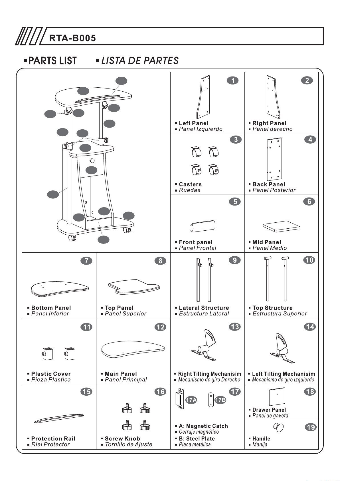
RTA-B005
Multi-Functional Computer Table
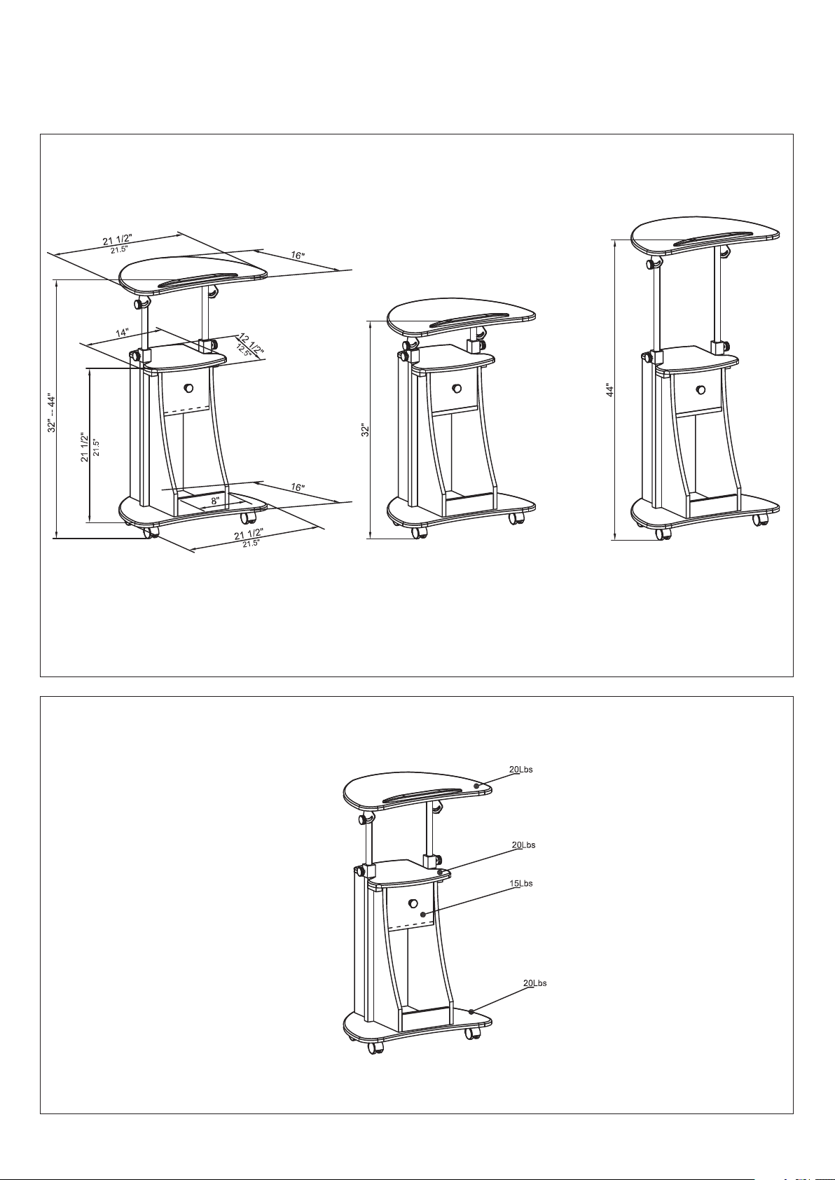
DIMENSIONS
Product Size: 21.5"W x 16"D x 32~44"H
MAXIMUM WEIGHT CAPACITIES
Lowest position
Highest position
DO NOT exceed this limit
Please use care and good judgement
when placing objects on wood surface
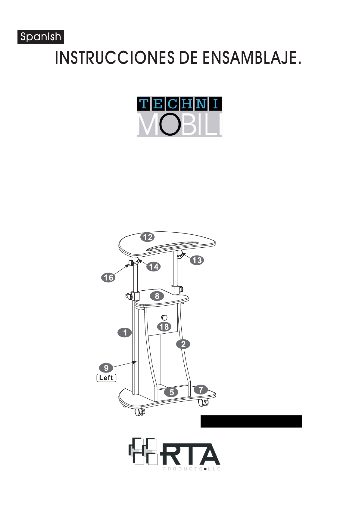
12
P.4
15
16
2
5
13
10
7
14
10
9
11
8
18
1
P.5
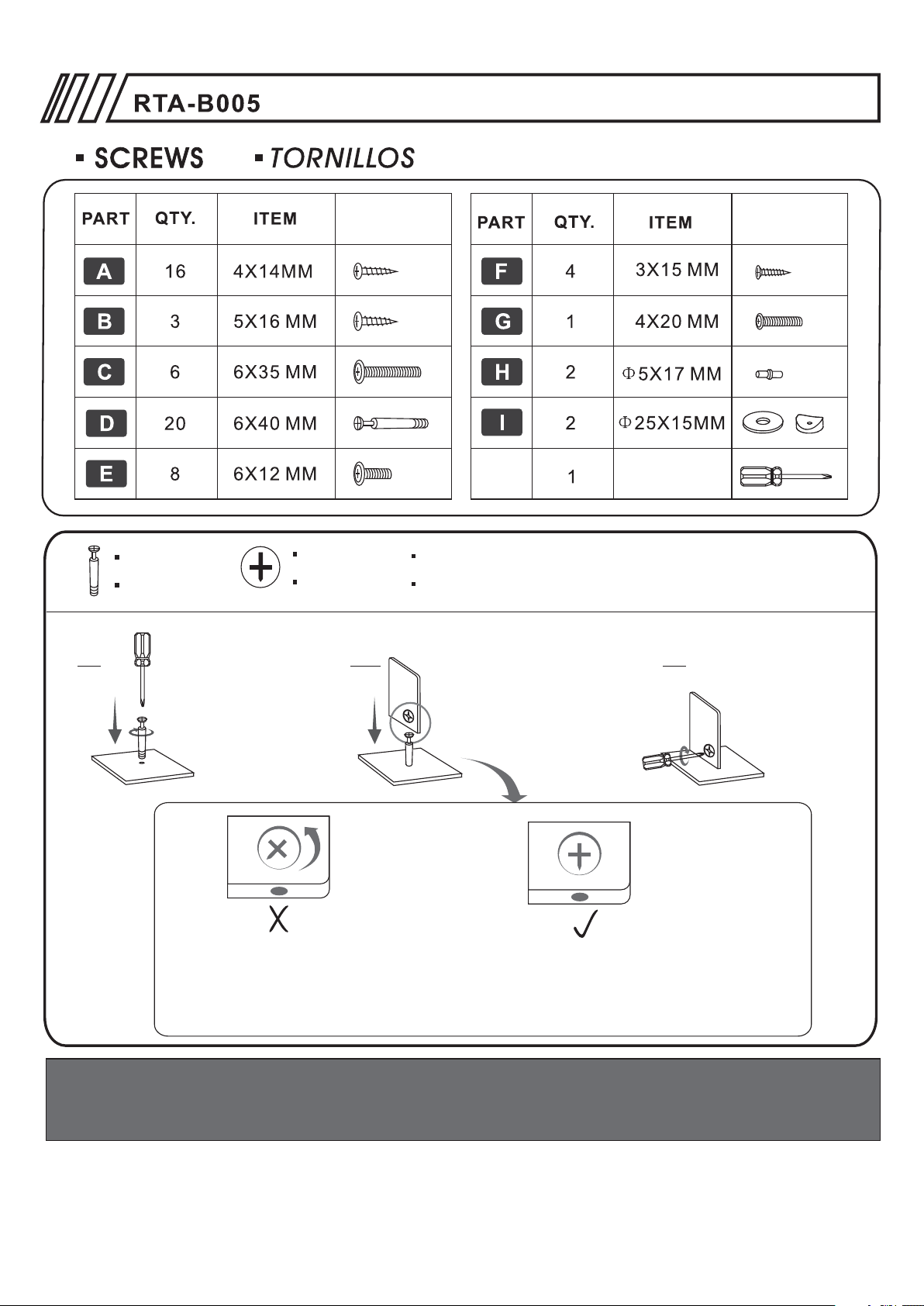
Cam bolt
Perno
1. 2. 3.
Screw bolt into the
corresponding panel.
Atornille el perno en el
panel correspondiente.
Cam lock
Cerraje
6X40MM BOLT INSTALLATION AS BELOW:
6x40mm INSTALE EL PERNO ASI:
Join the panels by inserting
the bolt into the hole with
the cam lock.
Junte los paneles insertando
el perno en el hueco que tiene
el cerraje.
INCORRECT:
Turn cam lock
incorrecto:
Gire el cerraje
Before assembling panels that use the cam bolt and cam lock, make sure that the cam lock is
aligned to receive the bolt.
Antes de ensamblar paneles que usan el perno y cerraje, aseg rese de que el cerraje est
alineado para recibir el perno.
CORRECT
correcto
5
ú é
Turn the cam lock.
Gire el cerraje.
ATTENTION: HOLES ON PANELS MAY BE HIDDEN UNDERNEATH PVC LAMINATE!!!
DO NOT TIGHTEN THE SCREWS UNTILL ALL OF THEM ARE IN THE RIGHT POSITION.
ATENCION: LOS HUECOS PUEDEN ESTAR ESCONDIDOS BAJO EL LAMINADO DE PVC!!!
NO APRIETE NINGÚN TORNILLO HASTA QUE TODOS ESTÉN EN LA POSICION C RRECTA.Ó
ASSEMBLY TIPS ARE LOCATED AT THE END OF THE MANUAL.
Consejos tiles para el ensamblado se encuentran al final del
ú
manual.

P.6
1
17
17A 17B
2
Use Screws (F) to fix the Magnetic Catch (17A)
to the inside face of Top Panel (8).
Use Screws (F) to fix the Steel Plate (17B) to
the Drawer Panel (18).
Use tornillos (F) para fijar el cerraje magn tico (17A)
en la cara interior del panel superior (8).
Use los tornillos (F) para fijar la placa metalica (17B)
al panel de gaveta (18).
SCREWS
3X15 MM
F
é
TORN ILLOS
18
17A
8
17B
4PCS
Screw Bolts (D) to the inside face of the Left Panel (1).
Place the Back Panel (4), the Front Panel (5) and the Mid
4
6
5
Panel (6) over the Bolts (D) and secure them tightening
the cam locks in the Back Panel (4), the Front Panel (5)
and the Mid Panel (6).
3
18
Use los Pernos de Ajuste D para fijar el Panel Medio (6),
Panel Posterior (4) y el Panel Frontal (5) al Panel lizquierdo.
Asegurese de ajustar los cerrajes en la cara posterior de los
Paneles (6,4 y 5) para asegurar los Pernos.
1
SCREWS
6X40 MM
D
TORN ILLOS
4PCS
Insert one double side Pin (H) into the holes on the edge
of the Drawer Panel (18), then insert the Bidirectional pin
into the hole on the inside face of the Left Panel (1).
Inserte un pasador doble (H) en los huecos al borde del
Panel de Gaveta (18), después inserte el pasador en el
hueco de la parte interior del Panel Izquierdo (1).
SCREWS
TORN ILLOS
H
Φ5X17 MM
1
H
1PC

P.7
4
Screw Bolts (D) to the inside face of the Right Panel (2).
Insert the other double side Pin (H) into the hole of Drawer
2
4
Panel (18). Join the panel (2) with the semi structure built
in step 3, and make sure to turn all the corresponding cam
locks on panels (4) and (6) to secure the bolts.
Atornille los pernos (D) a la parte interior del Panel Derecho (2).
Inserte el otro pasador doble (H) en el hueco del Panel de
Gaveta (18). Junte el panel (2) con la semi estructura construida
en el paso 3, y haga girar los cerrajes correspondientes en los
paneles (4) y (6) para asegurar los pernos.
5
18
SCREWS
6
H
6X40 MM
D
TORN ILLOS
4PCS
Φ5X17 MM
H
1PC
6
5
Use Screws (A) to assemble the Casters (3) to the back
side of the Bottom Panel (7). Make sure the 2 locking
casters are facing to the front.
X2
3
7
4
2
1
3
Screw Bolts (D) to the Bottom Panel (7). Then place the Left,
Right and Back Panels (1,2,4) over the Bolts (D) and secure
them tightening the connecting pieces in the Left and Right
Panel (1&2), the Back Panel (4).
Atornille los pernos (D) en la superficie interior del panel
Inferior (7) . Coloque los Los Paneles Izquierdo, Derecho y
Posterior (1,2,4) sobre los pernos (D) del panel Inferior (7)
Finalmente aseg relos girando los cerrojos en los paneles
posterior (4), lzquierdo (1) y derecho (2).
Con tornillos A fije las Ruedas (3) a la cara posterior del
Panel Inferior (7). Aseg rese que las ruedas con el cerraje
X2
queden puestas en la parte de adelante.
ú
SCREWS
4X14 MM
A
TORN ILLOS
16PCS
ú
SCREWS
6X40 MM
D
7
TORN ILLOS
6PCS

P.8
8
7
Screw Bolts (D) to the inside face of the Top Panel (8) .
Then insert the Bolts into the holes of the Back, Left
8
4
and Right Panels (4,1,2). Finally tighten the cam locks
in the Back Panel (4) and the Left & Right Panel (1&2).
Atornille los pernos (D) en la superficie interior del panel
superior (8) . Luego insérte los pernos en los huecos de los
paneles posterior, izquierdo y derecho (4,1 y 2).
Finalmente, asegure los pernos girando los cerrojos en los
paneles posterior (4) y los paneles izquierdo y derecho (1 y 2).
2
1
SCREWS
6X40 MM
D
TORN ILLOS
6PCS
9
Use Screws (C) to fix both Lateral Structures (9)
to the Bottom Panel (7) and to the Left & Right
Panels (1&2).
Use Tornillos C para Fijar ambas Estructuras
Laterales (9) a los Paneles Izquierdo y Derecho
(1 y 2) y luego al Panel Inferior (7).
9
16
13
1
10
10
2
SCREWS
6X35 MM
C
TORN ILLOS
6PCS
Place the Washers (I) between the Right Tilting Mechanism (13)
and the Top Structure (10) as shown in the drawing, then use the
Screw Knob (16) to assemble them together. Repeat the same
procedure with the Left Tilting Mechanism (14).
Coloque las Arandelas (I) entre el mecanismo de giro derecho (13)
y la estructura superior (10) seg n el dibujo, luego use el tornillo de
ajuste (16) para que queden ensamblados juntos. Haga lo mismo para
el mecanismo de giro izquierdo (14).
ú
16
TORN ILLOS
14
SCREWS
I
Φ25X15MM
2PCS

10
13
12
14
P.9
Use Screws (E) to fix the Left & Right Tilting
Mechanisms (13&14) to the Main Panel (12).
Use Tornillos (E) para fijar los Mecanismos de
giro Izquierdo y Derechos (13 y 14) al Panel
Principal (12).
11
11
SCREWS
6X12 MM
E
TORN ILLOS
8PCS
10
X2
9
16
16
Assemble the Plastic Cover (11) to the
Lateral Structure (9).
Slide the Top Structures (10) into the
Plastic Covers (11). Screw in the
Knobs (16) into the Plastic Covers (11).
Coloque la piezas plasticas (11) sobre los
tubos de la Estructura Lateral (9).
Deslize las Estructuras principales (10)
dentro de las Piezas Plasticas (11). Inserte
y Ajuste los Tornillos de Ajuste en Las
piezas Plasticas (11).

12
P.10
15
12
Use Screws (B) to fix the Protection Rail (15) to the
Main Panel (12).
Luego usando Tornillos B fije el Riel de Proteccion (15)
al Panel Principal (12).
13
18
SCREWS
B
TORN ILLOS
5X16 MM
3PCS
Use Screw (G) to fix the Handle (19) to the Drawer
Panel (18).
Use los tornillos (G) para fijar la manija (19) al panel
de gaveta (18).
19
SCREWS
4X20 MM
G
TORN ILLOS
1PC

CARE AND MAINTENANCE
English
- DO NOT EXPOSE THE SURFACES TO DIRECT SUNLIGHT, OR
EXTREME ENVIRONMENTAL CONDITIONS. EXPOSURE WILL
DAMAGE THE PRODUCT, WHICH IS NOT COVERED BY THE
WARRANTY.
- DO NOT USE SOLVENTS OVER SURFACES OR STRUCTURAL
TUBES. SURFACES MUST BE CLEANED WITH A SOLUTION OF
A SMOOTH SOAP AND WATER, THEN CLEARED WITH A DRY
TOWEL.
- PRODUCTS THAT ARE HEAVY SHOULD BE LIFTED OR MOVED
BY AT LEAST 2 PERSONS, AND ALL OBJECTS SHOULD BE
REMOVED FROM THE PRODUCT.
Spanish
- NO EXPONGA LAS SUPERFICIES A LA LUZ SOLAR DIRECTA,
O A CONDICIONES AMBIENTALES EXTREMAS. ESTE TIPO DE
DAÑOS NO SON CUBIERTOS POR LA GARANTÍA DEL PRODUCTO.
- NO USE SOLVENTES SOBRE LAS SUPERFICIES O TUBOS
ESTRUCTURALES. LAS SUPERFICIES DEBEN SER LIMPIADOS
CON UN JABÓN SUAVE Y AGUA, Y SECADOS IMMEDIATAMENTE
CON UNA TOALLA LIMPIA Y SECA.
- PRODUCTOS QUE SON PESADOS DEBEN LEVANTARSE O
MOVERSE POR AL MENOS 2 PERSONAS, Y TODOS LOS
OBJETOS DEBEN SER REMOVIDOS DEL PRODUCTO.

HELPFULL ASSEMBLY TIPS
CONSEJOS ÚTILES DE ENSAMBLAJE
- MAKE SURE THE PACKAGE CONTAINS ALL THE PARTS
LISTED IN THE LIST OF PARTS, INCLUDING ANY HARDWARE.
- ASEGÚRESE QUE EL PAQUETE CONTENGA TODAS
LAS PARTES QUE MUESTRA LA LISTA DE
PARTES, INCLUYENDO TORNILLOS.
PART N0. DESCRIPTION QTY
FRAME
1
SOPPO RT
2
BACK PANEL
3
GLIDE
4
TABL ETOP
5
6x20m m SC REW
A
6x30m m SC REW
B
TOO L
C
2
2
1
4
1
4
8
1
1
- FOLLOW THE ASSEMBLY INSTRUCTIONS STEP BY STEP,
AND DO NOT SKIP ANY, UNLESS ADVICED TO DO SO
BY AN RTA PRODUCT’S TECHNICIAN.
3
- SIGA LAS INSTRUCCIONES PASO POR PASO, Y NO SALTE NINGUNO,
A MENOS QUE SE LO ACONSEJE UNO DE NUESTROS TÉCNICOS.
- ON EACH STEP, AND TO AVOID MISALIGNMENTS,
ALWAYS LEAVE SCREWS LOOSE,
AND DO NOT TIGHTEN THEM UNTIL ALL ARE IN PLACE.
2
2
SCRE WS
6X65 M M
1
3
4
1
4PCS
1
SCRE WS
6X50 M M
A
2PCS
5
1
SCRE WS
6X30 M M
C
4PCS
1
3
4
1
B
1
1
SCREW
LOOSE!
- EN CADA PASO, Y PARA EVITAR DESALINEAMIENTOS,
SIEMPRE DEJE LOS TORNILLOS FLOJOS A MEDIO ATORNILLAR,
Y APRIÉTELOSCUANDO TODOS ESTÉN COLOCADOS.

30mm
30mm
- MAKE SURE TO USE THE CORRECT SCREWS OR BOLTS
35mm
35mm
AND DO NOT OVERTIGHT THEM.
DOING SO MIGHT CAUSE DAMAGE TO THE PARTS
OR PRODUCTS WHICH IS NOT
CORRECT SIZE OF SCR EW.
TOR NI LL O DE M ED ID A
CARRECTA.
COVERED BY THE PRODUCT’S WARRANTY.
- ASEGÚRESE DE USAR LOS TORNILLOS Y PERNOS CORRECTOS
Y NO LOS APRIETE DEMASIADO.
HACERLO PODRÍA DAÑAR LAS PARTES O EL PRODUCTO,
Y LA GARANTÍA NO CUBRE ESTE TIPO DE DAÑOS.
- IN SOME WOOD PANELS THE LAMINATE MIGHT BE COVERING
THE HOLES. LOOK FOR INDENTENTIONS IN THE AREA WHERE
THE HOLE SHOULD BE. IF THE HOLES LOOK TOO
SMALL FOR A SCREW, JUST CAREFULLY PUSH THE SCREW THRU THEM.
X
SCREW WILL DA MA GE T HE PART!
EL TO RN IL LO C AUSARA DA NO S!
DOES THE HOLE LOO K TO O SM AL L?
EL HU EC O LU CE M UY P EQUENO?
- EN ALGUNOS PANELES DE MADERA, EL LAMINADO PUEDE
ESTAR CUBRIENDO LOS HUECOS. BUSQUE LA HENDIDURA EN EL
AREA DONDE EL HUECO DEBE ESTAR.
SI LOS HUECOS LUCEN MUY PEQUEÑOS, SÓLO EMPÚJE LOS TORNILLOS
CON CUIDADO A TRAVÉS DEL HUECO.
MISALIGNED NUT:
- SOME WOOD PANELS HAVE METAL INSERTS THAT LOOK
LIKE SCREWS. THESE PARTS ARE EITHER NUTS
OR CAM LOCKS. MAKE SURE THEY ARE ALIGNED
TO RECEIVE THE SCREWS OR BOLTS.
MISALIGNED CAM LO CK :
CAREFULLY PERFORATE.
PERFORELO CON
CUIDADO.
THE HOLE IS BIGGE R TH AN W HAT I T APP EA RE D.
EL HU EC O ES M AS G RA DE D E LO Q UE
APAR EN TAB A.
ALIGNED NUT:
X
ALIGNED CAM LOCK:
X
- CIERTOS PANELES TIENEN INSERTADOS METALES QUE
PARECEN TORNILLOS. ESAS PARTES SON TUERCAS O CERRAJES.
ASEGURESE QUE ESTEN ALINEADOS PARA RECIBIR LOS
TORNILLOS O PERNOS CORRESPONDIENTES.

 Loading...