

A S S E MB L Y I N S T R U C T I O N S
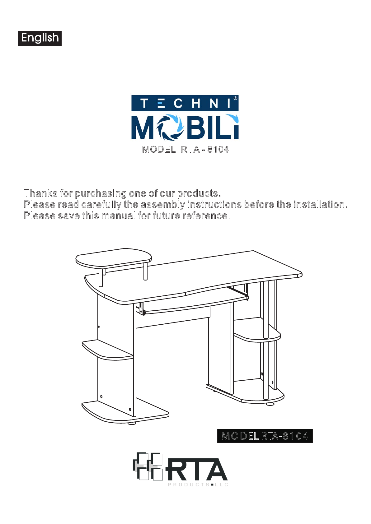
MODEL RTA - 8104
Thanks for purchasing one of our products.
Please read carefully the assembly instructions before the installation.
Please save this manual for future reference.
M O DEL R TA- 8 1 0 4
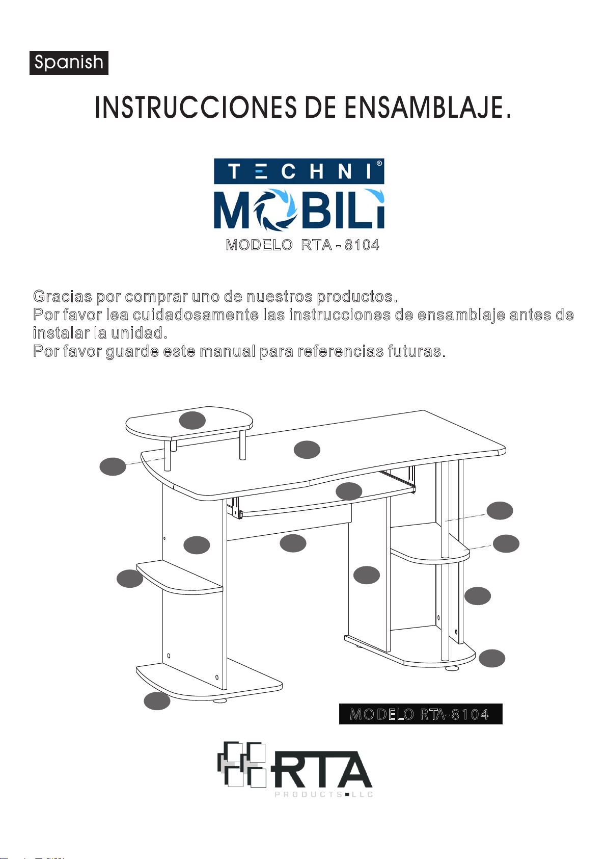
MODELO RTA - 8104
Gracias por comprar uno de nuestros productos.
Por favor lea cuidadosamente las instrucciones de ensamblaje antes de
i
nstalar la unidad.
Por favor guarde este manual para referencias futuras.
1 0
1
1 3
1 5
8
11
9
1 2
2
4
M O DELO RTA- 8 1 0 4
6
5
7
RTA-8104
16.5"
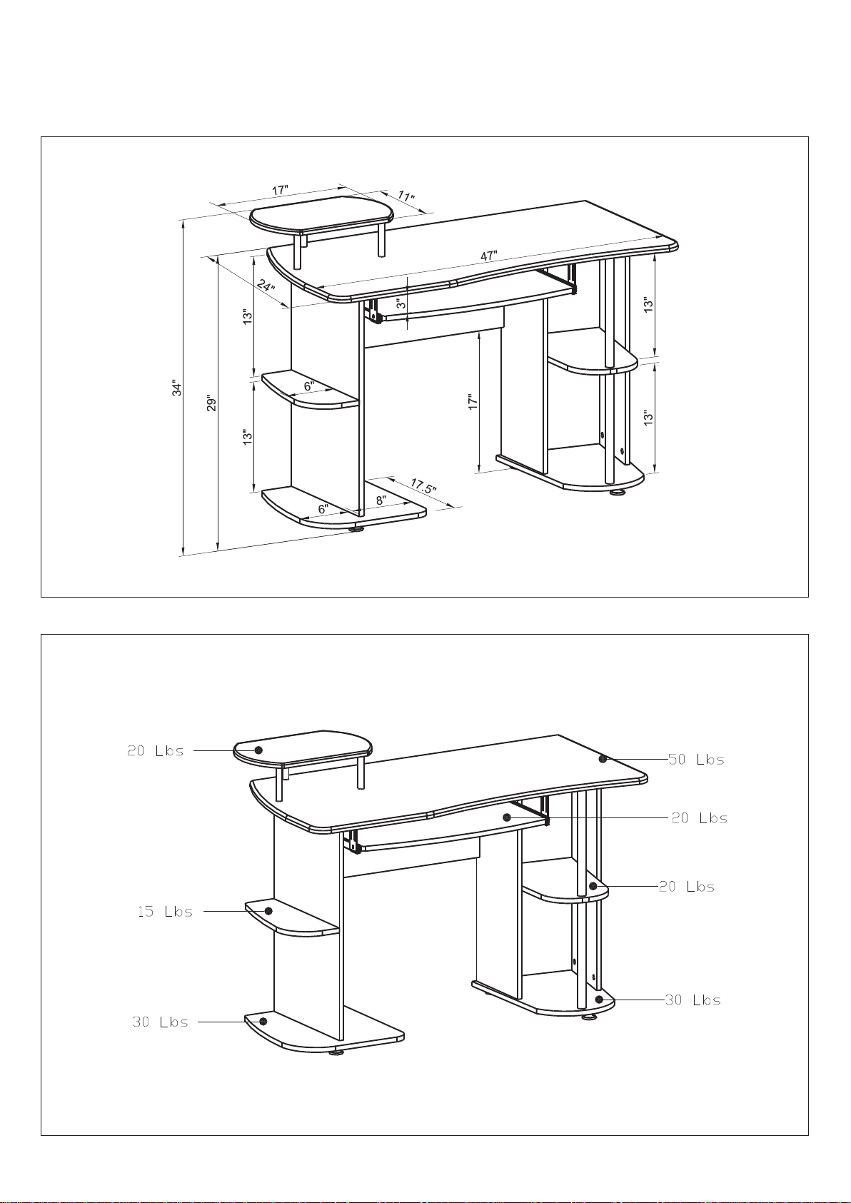
DIMENSIONS
Product Size: 47"W x 24"D x 34"H
MAXIMUM WEIGHT CAPACITIES
DO NOT exceed this limit
Please use care and good judgement
when placing objects on wood surface
RTA-8104
P.4
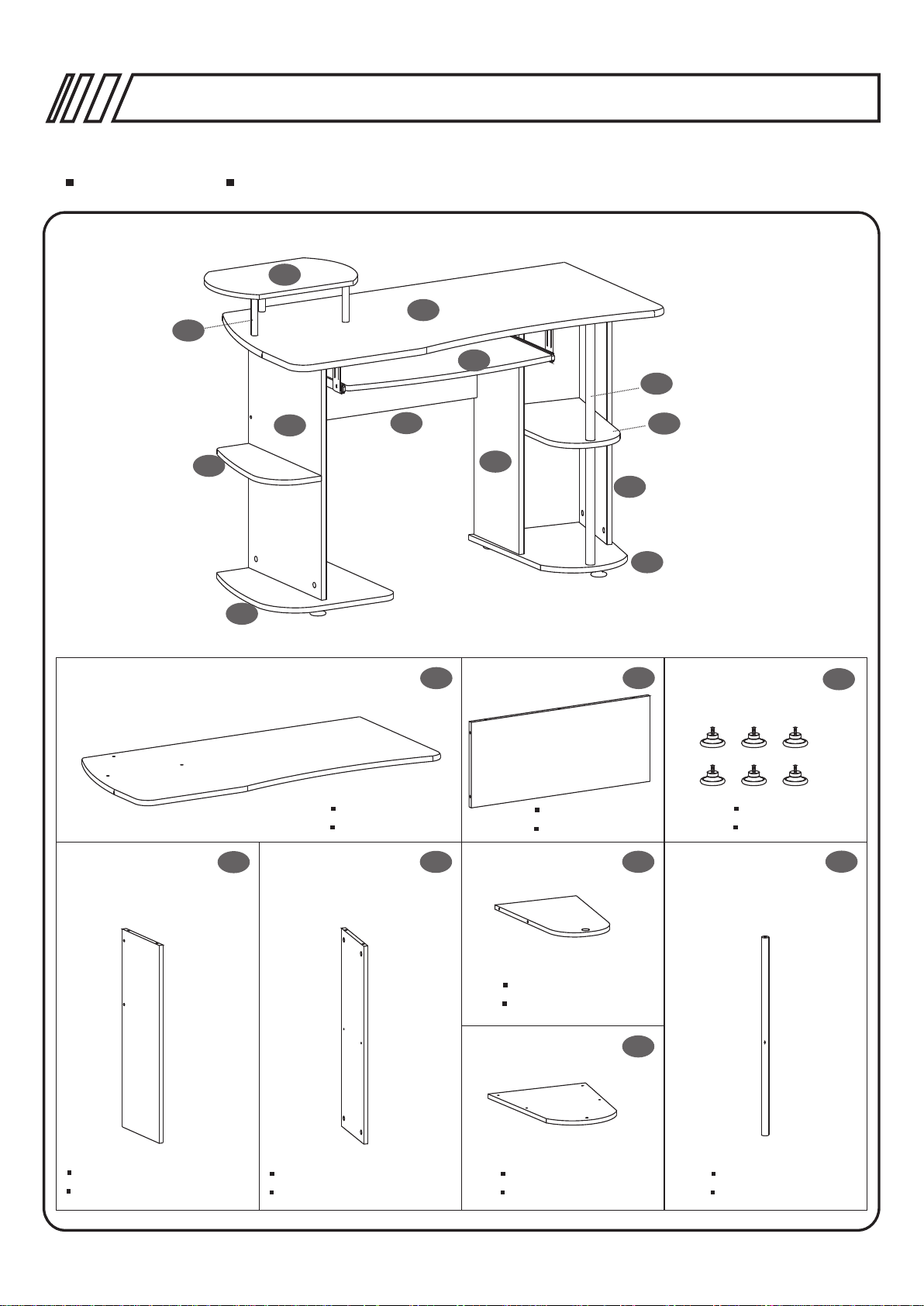
PARTS LIST
13
LISTA DE PARTES
10
11
9
12
1
15
8
2
6
4
5
7
1
Main Panel
Panel P rincipal
4
5
Back Panel
Panel P osterior
Auxiliary Panel
Panel Auxiliar
2
Studs
Topes
6
3
x6
8
7
Left Vertical Panel
Panel Vertical Izquierdo
Right Vertical Panel
Panel Vertical Derech o
Bottom Panel
Panel d e Fondo
Vertical Tube
Tobo Vertical

RTA-8104
P.5
Horizontal Panel
Panel H orizontal
Supporting Tube
Tubo de Soporte
Derecho
Right
9
13
x3
16
10 11 12
Printer Panel
Panel d e Impresora
14 15
Slider’s Base
Base de l os Deslizadores
x4
CPU Vertical Panel
Panel Vertical de CPU
CPU Bottom Panel
Panel d e Fondo de CPU
Keyboard Panel
Panel d e Tec lado
Left
Izquierdo
Slider
Desli zadores
SCREWS LIST
PART
A
B
C
QTY.
4
4
4
LISTA DE TORNILLOS
ITEM PART
6X35 MM
4X4 MM
6X25 MM
F
G
H
QTY.
4
4
2
ITEM
6X12 MM
4X14 MM
Φ16 MM
D
E
20
6
6X40 MM
6X50 MM
1

RTA-8104
HOW TO ASSEMBLE USING BOLTS AND CAM LOCKS:
C MO ENSAMBLAR USANDO LOS PERNOS Y CERRAJES:Ó
P.6
Cam bolt
Perno
1. 2. 3.
Screw t he bolt into the
corre sponding panel.
Atorn ille el perno al
panel c orrespondiente.
Cam lock
Cerraje
In the other panel, insert
and align the cam lock.
Join the panels.
En el otr o panel, inser te el
cerra je y alineelo.
Junte l os paneles.
If the panel already comes with the cam lock inserted, make sure is aligned:
Si los paneles ya vienen con los cerrajes, aseg rese que est n alineados:ú é
MISALIGNED:
TURN CAM LOCK
TO POINT TOWARDS
THE HOLE
DESALINEADO:
GIRE EL CERRAJE
PARA QUE APUNTE
HACIA EL HOYO.
Turn the cam lock.
Gire el c erraje.
CORRECT
CORRECTO

30mm
30mm
35mm
35mm
RTA-8104
P.7
GENERAL ASSEMBLY TIPS AND TROUBLESHOOTING DURING ASSEMBLY:
*Before you start assembling, make sure you have all the parts and necessary
hardware by doing a quick inventory.
*Follow the assembly instructions step by step, and do not skip any unless
advised to do so by RTA PRODUCTS’ Customer Service.
*On each step, and to avoid misalignments, always leave screws loose, and
do not tighten them until all are in place.
*In wood panels, the laminate might be covering the holes.
If there are no visible holes: Pass the tip of your finger around the area where
the hole should be, and press against the surface to feel the indentation.
If the hole looks too small for the screw of bolt: carefully perforate the laminate
with the tip of a pen.
DOES THE HOLE
LOOK TOO SMALL?
CAREFULLY
PERFORATE.
THE HOLE IS BIGGER
THAN WHAT IT APPEARED.
*In wood panels, some might have inserts that look like screws. Those inserts are
either nuts or cam locks. Make sure they are aligned to receive the screws or bolts.
Misal igned
nut
CORRE CT
Misal igned
cam loc k
CORRE CT
*Make sure to use the correct screws or bolts, and do not overtight them.
Using wrong screws or overtighting them might cause damage to the parts,
and such damage is not covered by the product’s warranty.
CORRECT SIZE OF SCREW
SCREW IS NOT OVERTIGHTEN
A WRONG SIZE OF SCREW
OR OVERTIGHTING IT WILL
CAUSE DAMAGE!

30mm
30mm
35mm
35mm
RTA-8104
P.8
CONSEJOS PARA RESOLVER PROBLEMAS DURANTE EL ENSAMBLAJE:
*Antes de comenzar, haga un inventario r pido para asegurarse de tener todas
á
las partes y tornillos necesarios.
*Siga las instrucciones paso por paso, y no se salte ninguno a menos que se lo
aconseje un representante de Servico al Cliente de RTA PRODUCTS.
*Para evitar desalineamientos, en cada paso que haga deje los tornillos medio
puestos, y no los apriete hasta que todos estén colocados en sus lugares.
*En paneles de madera, el laminado podr a cubrir las perforaciones.
í
Si no ve los hoyos: Pase la punta del dedo por el area y presione contra la
superficie para encontrar el hoyo.
Si el hoyo luce muy peque o para el tornillo o perno: Con cuidado perfore el
laminado con la punta de un lapicero (bol grafo, pluma).
El hoyo luce
demasiado peque o?ñ
ñ
ó
Perf relo
con cuidado.
í
El hoyo es m s
grande de lo que
aparenta.
á
*Algunos paneles pueden tener insertados lo que parecen tornillos, pero son
tuercas o cerrajes: Asegúrese que esten alineados para recibir el tornillo o perno.
Tuerca
desal ineada.
*Aseg rese de usar los tornillos y pernos correctos, y no los apriete demasiado.
ú
Usar tornillos/pernos de tama o incorrecto o sobre-apretarlos pede causar
da o a las partes, lo cual no es cubierto por la garant a del producto.
ñ í
Tornillo de tama o
correcto, sin sobre
apretar.
CORRE CTO.
ñ
ñ
Cerra je
desal ineado.
Tornillo de tama o
incorrecto o sobre
apretado causar
ñ
da o a la parte!
CORRE CTO.
ñ
á

RTA-8104
P.9
ATTENTION: THE ASSEMBLY STARTS WITH THE PARTS UPSIDE-DOWN.
ATENCI N: EL ENSAMBLANDO COMIENZA CON LAS PARTES AL REVÉS.Ó
Steps
Pasos
1
X4
14
1
Use Screws (F) to assemble the Slider’s Bases (14) to the back of Main
Panel (1).
Use Tornillos (F) para ensamblar las bases de los deslizadores (14) en
el rev s del Panel Principal (1).é
X4
2
14
SCR E WS
6X12 MM
F
4PCS
TOR N ILLOS
16
16
Right
Use Screws (B) to fix the Sliders (16) to the Bases (14).
Use Tornillos (B) para fijar los Deslizadores (16) a las Bases de los
Deslizadores (14).
Derecho
Left
Izquierdo
3
6
4
5
Insert the Bolts (D) in the holes of the Left & Right Vertical Panels (4&5)
and tight them with the screwdriver, then place the Auxiliary Panel (6)
over the Bolts and tight the cam locks on the inside face of the panels.
Inserte los Pernos (D) en los agujeros de los Paneles Verticales Izquierdo
e Derecho (4&5) y aj stelos con el destornillador, luego coloque el
Panel Auxiliar (6), haciendo coincidir los agujeros laterales con los
Pernos (D) y ajuste los cerrajes ubicadas en la cara interna de ste panel.
ú
é
SCR E WS
4X4 MM
B
SCR E WS
6X40 MM
D
TOR N ILLOS
4PCS
TOR N ILLOS
4PCS

4
RTA-8104
P.10
5
4
SCR E WS
1
Insert the Bolts (D) in the holes of the back side of Main Panel (1) and tight
them with the screwdriver, then place the Left & Right Vertical Panels (4&5)
over the Bolts (D) and tight the cam locks on the inside face of these panels.
Inserte los Pernos (D) en los agujeros de la parte posterior del Panel Principal (1)
y ajuste con el destornillador, luego coloque los Paneles Verticales Derecho e
Izquierdo (4&5) sobre los Pernos y ajuste los cerrajes colocadas en la cara interna
de stos paneles.é
6X40 MM
D
TOR N ILLOS
4PCS
5
8
6
1
Insert the Vertical Tube (8) through the Auxiliary Panel (6) and use Screws (C)
to fit it to the back of the Main Panel (1).
Inserte el Tubo Vertical (8) a trav s del Panel Auxiliar (6) y use Tornillo (C)
para fijarlo a la parte posterior del Panel Principal (1).
é
33 8m m 35 6m m
13.3"
8
14"
SCR E WS
6X25 MM
C
TOR N ILLOS
1PC

6
RTA-8104
5
P.11
7
Just insert the bolt through the hole
4
8
of Vertical Tube (8).Its function is to
help support the Panel (6).
S lo inserte e l perno en el agujero
ó
del Tubo Ve rtical (8). Su f unci n es
ayuda r a sostener el Pa nel (6).
ó
SCR E WS
6X40 MM
D
TOR N ILLOS
5PCS
Insert the Bolts (D) in the holes of the Bottom Panel (7) and tight them with
the tool, then place it over the Left & Right Vertical Panels (4&5) and tight
the cam locks on the inside face. Finally, insert the Bolt (D) into the Vertical Tube (8).
Inserte los Pernos (D) en los agujeros del Panel de Fondo (7) y ajuste con el destornillador, luego
coloquelo sobre los Paneles Verticales Derecho e Izquierdo (4&5) y ajuste los cerrajes colocadas en la
cara interna de estos paneles. Inserte un Perno (D) en el Tubo Vertical (8).
7
7
8
Use Screw (A) to fix the Vertical Tube (8) to the Bottom Panel (7).
Use Tornillo (A) para fijar el Tubo vertical (8) al Panel de Fondo (7).
SCR E WS
6X35 MM
A
TOR N ILLOS
1PC

8
RTA-8104
P.12
11
SCR E WS
6X40 MM
9
D
TOR N ILLOS
2PCS
6X50 MM
E
2PCS
12
Φ16 MM
H
2PCS
Use Screws (E&H) to fix the Horizontal Panel (9) to the CPU Vertical Panel (11).
Insert Bolts (D) to the CPU Bottom Panel (12), then place the bolts into CPU Vertical Panel (11) and tight the
cam locks on the CPU Vertical Panel (11).
Use Tornillos y arandelas (E&H) para fijar el Panel Horizontal (9) al Panel Vertical de CPU (11) y ajuste los
cerrajes en este panel.
9
11
1
Insert Bolts (D) to the back side of the Main Panel (1), then place the
CPU Vertical Panel (11) to the bolts and tight the cam locks on the CPU
Vertical Panel (11).
Inserte los Pernos (D) en los agujeros de la parte posterior del Panel
Principal (1), luego coloque el Panel Vertical de CPU (11) sobre los
pernos, y ajuste los cerrajes del Panel Vertical de CPU (11).
SCR E WS
6X40 MM
D
TOR N ILLOS
2PCS

10
RTA-8104
P.13
2
SCR E WS
1
6X40 MM
D
TOR N ILLOS
3PCS
Insert the Bolts (D) in the holes of the Main Panel (1) and tight them with the screwdriver, then place the Back
Panel (2) over the Bolts and tight the cam locks on the Back Panel (2).
Inserte los Pernos (D) en los agujeros del Panel Principal (1) y aj stelos con el destornillador, luego coloque
el Panel Posterior (2) sobre los pernos, y ajuste los cerrajes en el Panel Posterior (2).
11
3
ú
3
7
12
4
11
SCR E WS
TOR N ILLOS
2
6X50 MM
E
4PCS
Use Screws (E) to fix the Back Panel (2) between the Left Vertical Panel (4) & CPU Vertical Panel (11).
Fix the Studs (3) to the back of the Bottom Panel (7) & the CPU Bottom Panel (12).
Use Tornillos (E) para fijar el Panel Posterior (2) entre el Panel Vertical Izquierdo y el Panel Vertical
de CPU (4&11).
Fije los Topes (3) en la parte posterior del Panel de Fondo y del Panel de Fondo de CPU (7&12).

12
RTA-8104
P.14
15
15
16
Right
16
Left
SCR E WS
Carefully, and with the help of another person, turn the desk upright.
Use Screws (G) to fix the Keyboard Panel (15) to the Slider (16).
Con mucho cuidado, y con la ayuda de otra perona, voltee el mueble hacia arriba.
Use Tornillos (G) para ensamblar el Panel de Teclado (15) con los Deslizadores (16).
4X14 MM
G
16
TOR N ILLOS
4PCS
13
X3
13
SCR E WS
C
10
Use Screws (C) to fix the Supporting Tubes (13) to the Printer Panel (10).
Use Tornillos (C) para fijar los Tubos de Soporte (13) al Panel de Impresora (10).
TOR N ILLOS
6X25 MM
3PCS

14
RTA-8104
P.15
X3
13
1
Use Screws (A) to fix the Supporting Tubes (13) to the Main Panel (1).
Use Tornillos (A) para fijar los Tubos de Soporte (13) al Panel Principal (1).
15
15
SCR E WS
6X35 MM
A
TOR N ILLOS
3PCS
Tight all screws well and enjoy your unit.
Apriete todos los tornillos y disfrute su unidad.
15

CARE AND MAINTENANCE
English
- DO NOT EXPOSE THE SURFACES TO DIRECT SUNLIGHT, OR
EXTREME ENVIRONMENTAL CONDITIONS. EXPOSURE WILL
DAMAGE THE PRODUCT, WHICH IS NOT COVERED BY THE
WARRANTY.
- DO NOT USE SOLVENTS OVER SURFACES OR STRUCTURAL
TUBES. SURFACES MUST BE CLEANED WITH A SOLUTION OF
A SMOOTH SOAP AND WATER, THEN CLEARED WITH A DRY
TOWEL.
- PRODUCTS THAT ARE HEAVY SHOULD BE LIFTED OR MOVED
BY AT LEAST 2 PERSONS, AND ALL OBJECTS SHOULD BE
REMOVED FROM THE PRODUCT.
Spanish
- NO EXPONGA LAS SUPERFICIES A LA LUZ SOLAR DIRECTA,
O A CONDICIONES AMBIENTALES EXTREMAS. ESTE TIPO DE
DAÑOS NO SON CUBIERTOS POR LA GARANTÍA DEL PRODUCTO.
- NO USE SOLVENTES SOBRE LAS SUPERFICIES O TUBOS
ESTRUCTURALES. LAS SUPERFICIES DEBEN SER LIMPIADOS
CON UN JABÓN SUAVE Y AGUA, Y SECADOS IMMEDIATAMENTE
CON UNA TOALLA LIMPIA Y SECA.
- PRODUCTOS QUE SON PESADOS DEBEN LEVANTARSE O
MOVERSE POR AL MENOS 2 PERSONAS, Y TODOS LOS
OBJETOS DEBEN SER REMOVIDOS DEL PRODUCTO.
 Loading...