

MODEL RTA-7002
ASSEMBLY INSTRUCTIONS
Thank you for purchasing one of our products.
Please read carefully the assembly instructions before the installation.
Do not discard this manual or any of the packaging material until the unit
has been completely assembled
.
Imported By
P. 2
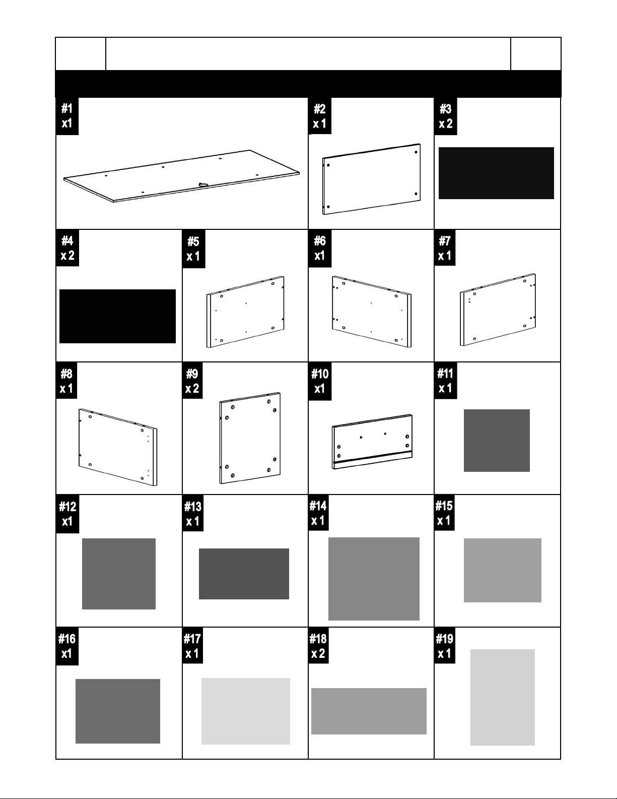
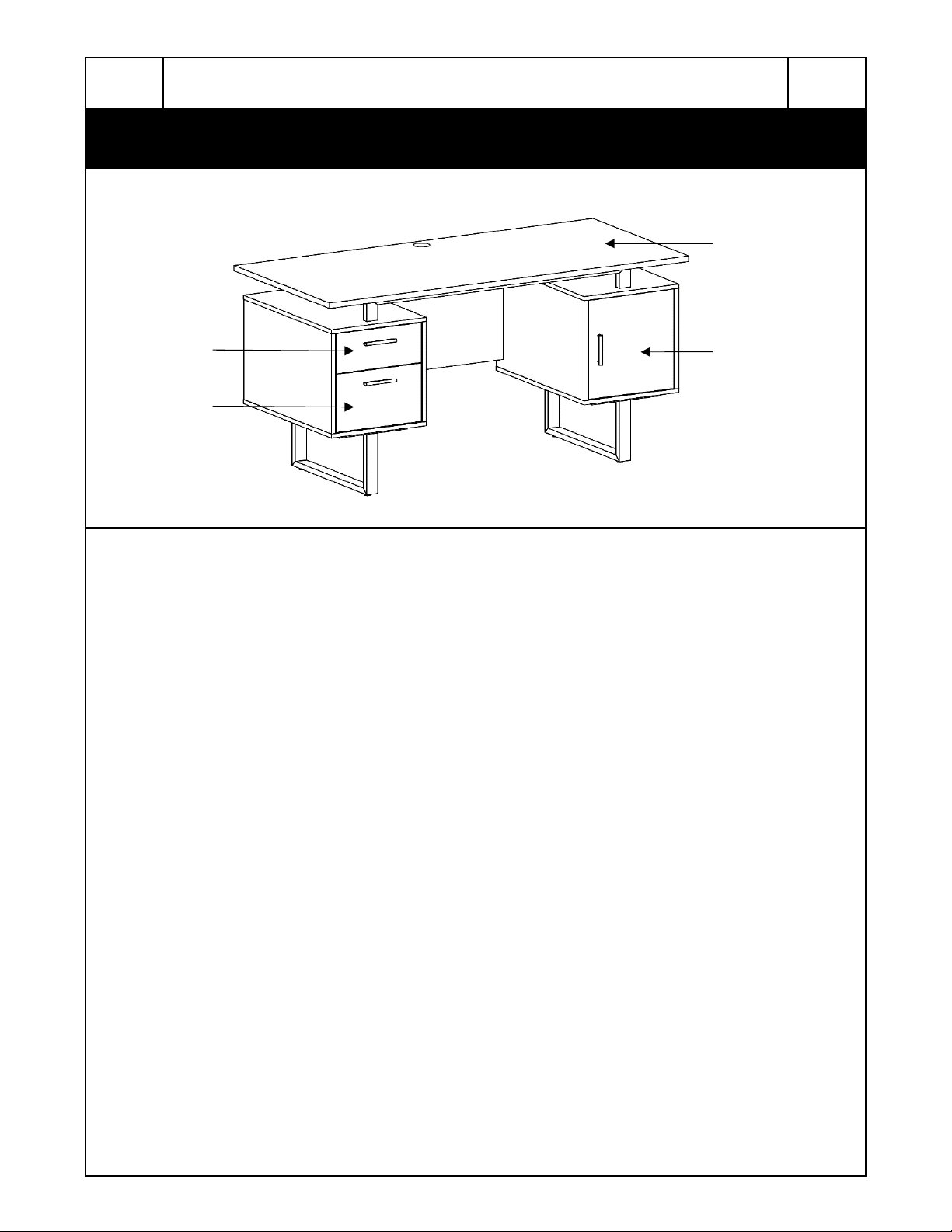
Main panel Back panel Cabinet Top panel
RTA-7002
MAIN PARTS LIST
P. 2
Cabinet bottom
panel
Right panel Cabinet back panel Small drawer front
Small drawer right
panel
Left panel Middle-Left panel Middle-Right panel
panel
Small drawer back
panel
Large drawer front
panel
Small drawer left
panel
Large drawer left
panel
Large drawer right
panel
Large drawer back
panel
Drawer bottom
panel
Door
P. 3
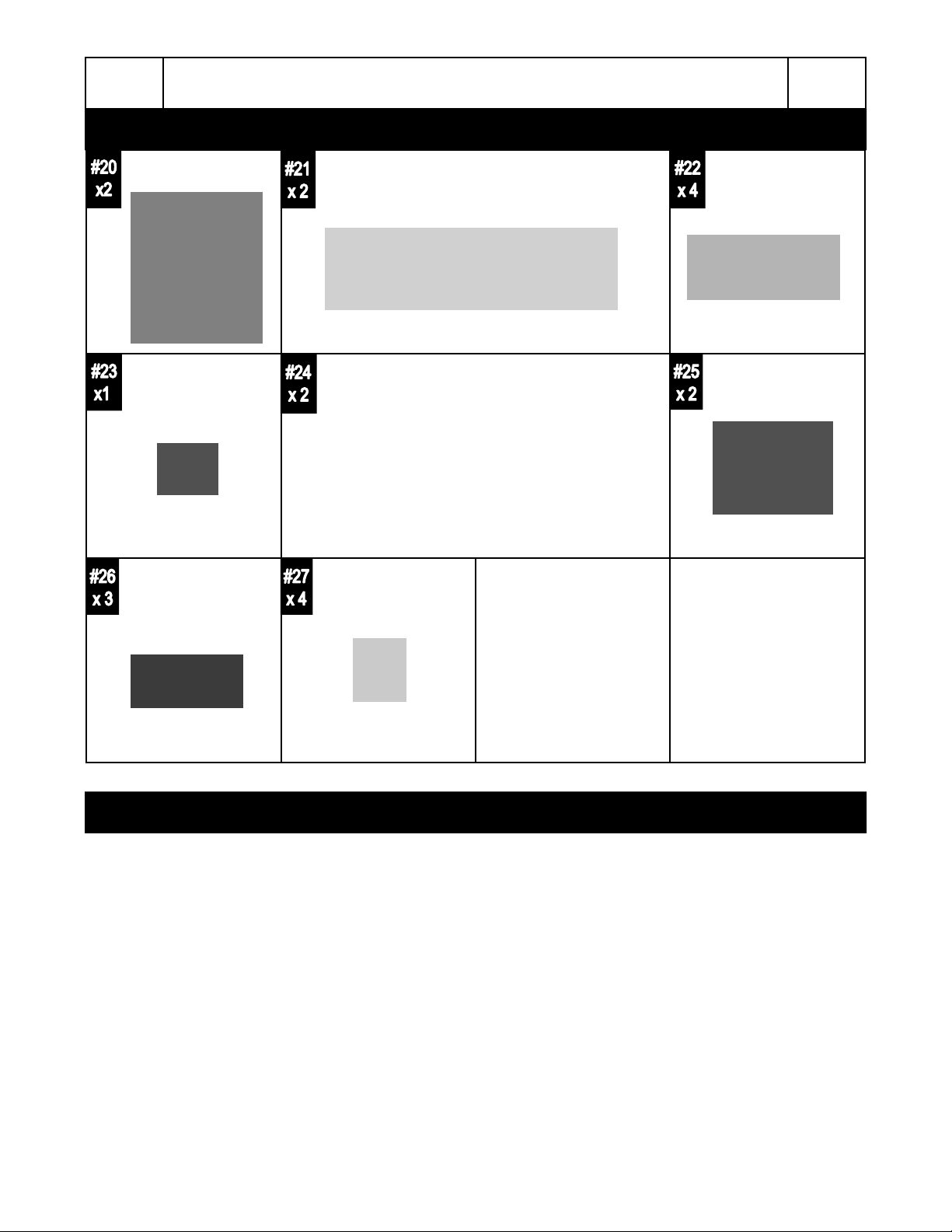
Legs Support tube for main panel Support tube for
RTA-7002
MAIN PARTS LIST
cabinet
P. 3
Cable management
(Grommet)
Handle Stud
Drawer sliders, SET of 4 pcs:
- 2 “flat” for inside the cabinets (CL, CR).
- 2 “L shaped” for the drawers (DL, DR).
Hinge
SCREWS LIST
P. 4
BEFORE YOU START THE ASSEMBLY, PLEASE READ THE FOLLOWING TIPS AND WARNINGS.
• Do a quick inventory to make sure the product contains all the parts and hardware.
• Missing, damaged and defective parts can be replaced at no cost to you. Please refer to the CONTACT card
included with the product.
• The replacement parts service is limited to the continental United States. If you reside in Hawaii, Puerto
Rico, U.S. Dependencies or other countries, please contact the supplier from where the unit was purchased.
• If during assembly you find an issue or need clarification, please contact our Customer Service for
assistance. Please refer to the CONTACT card included with the product.
• On each step read the instructions and analyze the illustrations thoroughly before proceeding to do the
assembly.
• Make sure you understand which hardware will be used on each step. Using the wrong size of screw, bolt or
pin might strip the threads or cause damage to the part in which it is being used.
• To avoid misalignments, always leave the screws loose and tighten them until all pieces are positioned
correctly.
• Do not overtighten or force the screws as they might break, strip, damage the threads of the holes or get
stuck inside the part.
• Sometimes the laminate might cover partially or entirely the hole on a panel, but the hole should still be
located under the laminate.
• If there is no visible hole for the screw, pass and press the tip of your finger over the area where the hole
should be located to feel the indentation, and once found, carefully pierce the laminate to reveal the hole
underneath.
• If the hole seems too small for the screw, first make sure you are using the correct size of screw and that it’s
been installed in the correct hole. If the hole still appears to be too small, carefully pierce the laminate to
reveal the hole’s actual size.
RTA-7002
P. 4
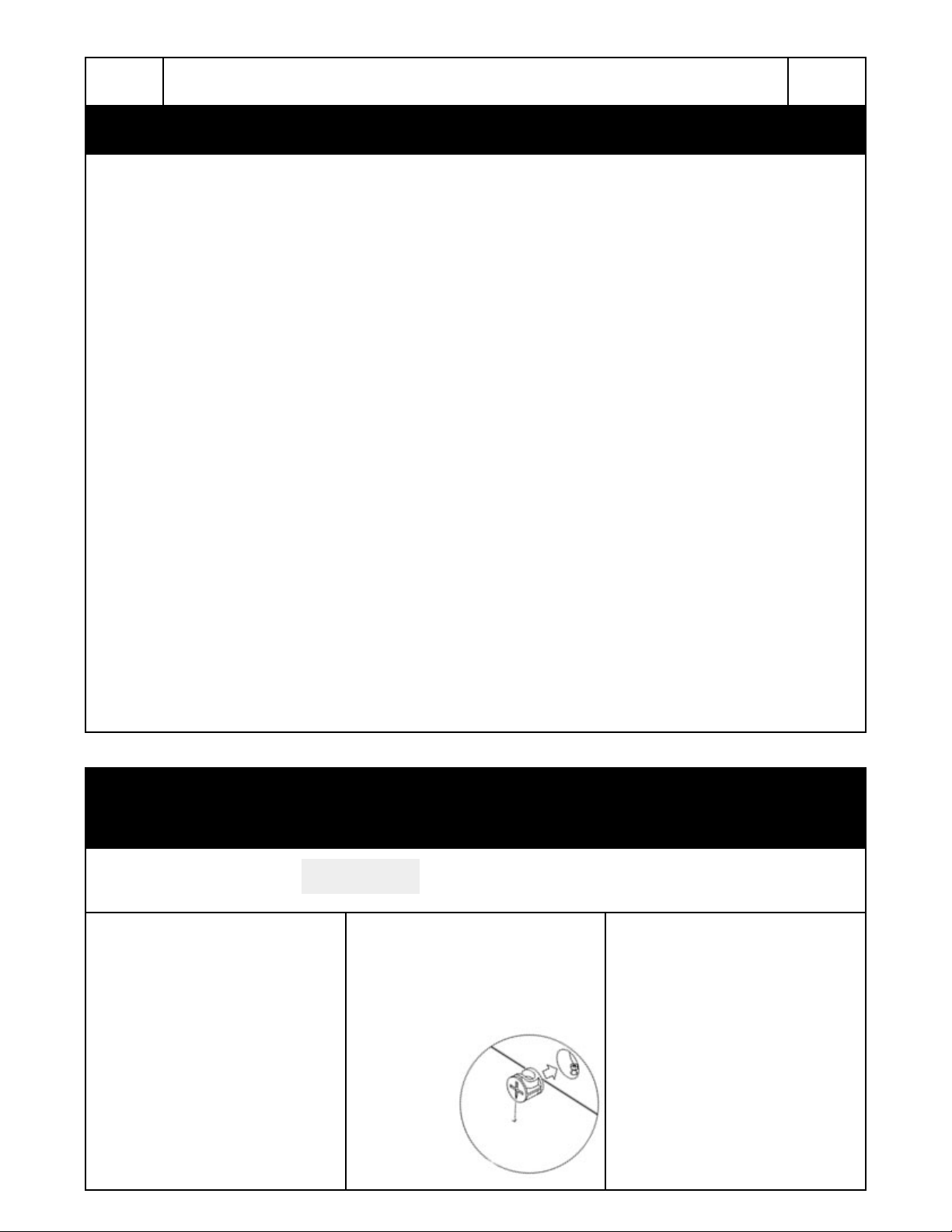
☛ This unit uses cam bolts and locks. The following explains how to use them.
This is not an assembly step; it is a guide for when you are actually doing the assembly using this
kind of hardware.
Cam Bolt
1. Screw the bolt into the
corresponding panel.
2. In the other panel, insert the
cam lock and align it so it can
properly receive the bolt, then join
both panels (the cam locks might
come pre-installed in this unit).
Cam Lock
3. The panels might have a very
small gap which is normal; turn the
cam lock clockwise to lock the
parts together and the gap will also
close.
ALIGNMENT
DIRECTION

P. 5
RTA-7002
ASSEMBLY STEPS
P. 5
STEP 1
STEP 2
Screws:
3x14mm 8
J
Separate the sliders (24) according to their shapes:
The “L” shaped sliders for drawer (DL, DR) will be used until step 6, please set them aside.
The flat sliders for cabinet (CL, CR) are the ones being used in step 2.
Assemble the flat drawer sliders (24) to the panels (5) and (6) using screws (J) as shown.
Note that the wheels face to the front and pay attention to the correct hole for the screw.
pcs
(Back)
A
STEP 3
Screws:
M6x35mm
(Back)
First install the bolts (A) into panels (5) and (6), then install and align the cam locks (A) into
panel (9), and assemble it to panels (5) and (6) as shown and as explained in page 4.
4
pcs
1st
2nd: install cams
4th: lock the cams
3rd
3rd
(Panels 5 & 6 are shown upside-down)

P. 6
RTA-7002
P. 6
A
B
A
STEP 4
Screws:
M6x35mm
⌀8x30
STEP 5
Screws:
M6x35mm
First insert the bolts (A) and the wooden pins (B) into the corresponding holes on panel (4),
then install and align the cam locks (A) into panels (5), (6) and (9), then assemble panel (4)
as shown and as explained in page 4.
6
pcs
4
pcs
1st
First install the bolts (A) into panels (7) and (8), then install and align the cam locks (A) into
panel (9), and assemble it to panels (7) and (8) as shown and as explained in page 4.
4
pcs
2nd: install cams
4th: lock the cams
3rd
2nd: install
cams
4th: lock the
cams
(Panels 5 & 6 are
shown upside-down)
A
B
STEP 6
Screws:
M6x35mm
⌀8x30
1st
First insert the bolts (A) and the wooden pins (B) into the corresponding holes on panel (4),
then install and align the cam locks (A) into panels (7), (8) and (9), then assemble panel (4)
as shown and as explained in page 4.
6
pcs
4
pcs
1st
3rd
3rd
(Panels 7 & 8 are
shown upside-down)
3rd
2nd: install
4th: lock the
cams
cams
(Panels 7 & 8 are
shown upside-down)

P. 7
RTA-7002
P. 7
STEP 7
STEP 8
Screws:
M6x35mm 8
E
Insert the studs (27) into the legs (20) as shown.
Assemble the support tubes (22) to the legs (20) using screws (E) as shown.
pcs
STEP 9
Screws:
M6x25mm 8
F
Assemble the bars (22) from each leg to each panel (4) on both cabinets using screws (F)
as shown.
pcs
(Front)
(Cabinets are shown upside-down)
(Front)

P. 8
RTA-7002
P. 8
STEP 10
Screws:
M6x50mm 4
C
3x14mm 2
J
K
M6-⌀10
L
First insert the nuts (L) into the panel (2) and make sure they are aligned to receive the
screws. Then assemble both cabinets to panel (2) using screws (C). Finally, assemble the
metal plate (K) to panel (7) using screws (J) as shown.
pcs
pcs
1
pc
4
pcs
STEP 11
Screws:
M6x35mm
A
⌀ 8x30
B
1st: install cams
Last: lock the cams
12
sets
8
pcs
First insert and align the cam locks (A) into panels (5), (6), (7), (8) and (9). Then insert the
bolts (A) and the wooden pins (B) into the corresponding holes on panels (3). Finally,
assemble the panels (3) to both cabinets as shown and as explained in page 4.
2nd
3rd
2nd
3rd

P. 9
RTA-7002
P. 9
STEP 12
Screws:
M6x40mm 6
D
Assemble the support bars (21) to
the tabletop (1) using screws (D)
as shown.
pcs
(Tabletop shown
Upside-down)
STEP 13
Screws:
M6x35mm
E
Assemble the support bars (21) to
the top panels (3) using screws
(E) as shown.
8
pcs
Note the hole for grommet
goes on the back of the
tabletop
STEP 14
Screws:
3.5x40mm
G
Using screws (G), assemble the
back panel (13) to panels (11)
and (12), and the panel (17) to
panels (15) and (16) as shown.
8
pcs
STEP 15
Insert the panel (18) in between the panels (11) and
(12), and also in between (15) and (16) as shown.

P. 1 0
RTA-7002
P. 10
STEP 16
Screws:
M6x35mm
A
M4x22mm 4
H
2nd: install
cam locks
First attach the bolts (A) to the panels (10) and (14). Then install the cam locks (A) into
panels (11), (12), (15) and (16). Then, and as explained in page 4, assemble the front
panel (10) to panels (11) and (12), and the front panel (14) to panels (15) and (16). Finally,
install the handles (26) to the front panels (10) and (14) using screws (H) as shown.
8
sets
1st
Last
2nd: install
cam locks
pcs
3rd
1st
Last
3rd
STEP 17
Screws:
3x14mm
J
Assemble the “L” shaped sliders (24) to the bottom of the drawers using screws (J) as
shown. Please note the orientation of the sliders: the rollers go towards the back, and they
should not protrude on the bottom, otherwise the drawers raise 3/4” and won’t fit in the unit.
8
pcs
ATTENTION:
VERY
IMPORTANT!
(Drawers shown upsidedown with front facing away)
The wheel goes
towards the back

P. 11
RTA-7002
P. 11
STEP 18
Screws:
M4x22mm 2
H
3.5x14mm 12
I
1st: Insert the drawers into the cabinet, the bottom drawer first, then the top drawer.
The top drawer might need to be inserted at an angle with its front facing down.
2nd: Assemble the handle (26) to the door (19) using screws (H).
3rd: Insert the Grommet (23) into the hole of the tabletop (1).
pcs
4th: Assemble the hinges (25) to panel (8) using screws (I).
5th: Assemble the door (19) to the hinges (25) using screws (I). The adjustment of the
pcs
hinges is explained below.
☛ If the drawers don’t fit properly, verify the
correct assembly of the sliders as explained
in page 5 step 2 and page 10 step 17.
☛ If the door does not close properly, you
can adjust the alignment of the hinges by
adjusting the following screws:
Adjusts the depth.
DONE! Before you start using the unit, make sure that all the screws, bolts, cam locks,
etc. are properly tightened, and read all the warnings in the next page.
P. 1 2
RTA-7002
AFTER THE ASSEMBLY IS DONE, PLEASE READ CAREFULLY THE FOLLOWING
CARE AND MAINTENANCE WARNINGS:
WEIGHTLIMITS
110Lbs. (49.9Kg)
P. 1 2
10Lbs. (4.53 Kg)
15Lbs. (6.8 Kg)
• Do not exceed the indicated weight limits.
• Do not expose the surfaces to direct sunlight or to extreme environmental conditions.
• Clean the surfaces preferable with a clean cloth damped in a solution of mild soap and water, then dry with a
clean towel.
• Do not use solvents or abrasive materials to clean the unit.
• If you decide to use a cleaning agent, test first on an area hidden from view such as underneath the
tabletop.
• Do not seat on the unit or lean against it.
• Do not allow small children to play under or over the unit, or inside the right cabinet.
• Do not allow small children to reach inside the drawers or the left cabinet without your supervision.
• Do not drag or push the unit to move it, it must be lifted by 2 persons when moving in the same or adjacent
rooms.
• Before moving the unit, make sure to remove any object that is heavy or might fall off.
• When lifting the unit, use both hands and bend your knees, not your backs.
• When transporting the unit to places far away, protect and secure the unit to avoid damage in transit.
• Shall any part of the unit become defective during the warranty period, replacement parts might be available
to you at no charge. Please refer to the WARRANTY card included with the product.
• The warranty does not extend to regular wear and tear, nor the manufacturer assumes liability for damages
or consequences due to accidents, incorrect assembly, negligence, improper use, modifications, or not
heeding the above warnings.
• The warranty is limited to the continental United States. If you reside in Hawaii, Puerto Rico, U.S.
Dependencies or other countries, please contact the supplier from where the unit was purchased.
33Lbs. (15 Kg)
 Loading...