

Page 1
In
formation specifically for:
IL-TRACKER575W/1
This manual contains important information.
Please read before operating fixture.
V1.2
Page 2

© 2005 Techni-Lux Inc.
2
Page 3

IMPORTANT INFORMATION
Save original packing and documentation for warranty, service and return issues.
Limited Warranty: This warranty covers defects or malfunctions in this equipment. This warranty lasts
for a period of one year from date of purchase. It is the owner’s responsibility to provide invoices for
proof of purchase, purchase date and dealer or distributor. If purchase date can not be provided,
warranty period will start at manufacture date. It is the sole discretion of Techni-Lux to repair or replace
parts or equipment. All shipping will be paid by purchaser. This warranty does not cover lamps, fuses,
belts, power semiconductors, relays, cleaning, standard maintenance adjustments or normal wear items
or any problem resulting from the following: improper wiring, incorrect voltage (including low or over
voltage conditions and lightning), abuse, misuse, improper maintenance or an act of God or damage
resulting from shipping. Warranty will be null and void if the product is altered, modified, misused,
damaged, or subjected to unauthorized repairs. Lamps are covered by relevant manufacturer warranty.
This warranty gives you specific legal rights, and you may also have other rights which vary from state to
state. Any liability for consequential and incidental damages is expressly disclaimed. No other warranty,
expressed or implied is made. Techni-Lux liability in all events is limited to, and shall not exceed, the
purchase price paid.
Returning equipment and Repairs: All returns must be accompanied by a Return Merchandise
Authorization (RMA) number and sent pre-paid. Contact the dealer or Techni-Lux directly to obtain an
RMA. The RMA number must be clearly listed on the shipping label. Due care must be exercised in
packing all merchandise to be returned. All repairs must be accompanied by a written explanation of the
claimed problem or error encountered. Techni-Lux is solely responsible for determining a product’s
eligibility for coverage under warranty. If returning for consideration of credit, all accessories and
documentation, original protective material and cartons must be included and the equipment, packing
and carton must be in new resalable condition. Credit for returned merchandise will be issued at the
lowest current price and is subject to a restocking fee of 20%. No returns accepted on discontinued
items. Techni-Lux is not responsible for merchandise damaged in transit and reserves the right to refuse
any return that is damaged by the carrier, not accompanied by a Return Authorization Number (RMA#) or
sent by freight collect.
Claims: All claims must be made within seven (7) days of receipt of merchandise. Any physical
damage must be reported to carrier upon receipt of merchandise.
Please record the following information for future reference:
Model Number: IL-TRACKER575W/1
Serial Number: ________________________________________
Dealer: ______________________________________________
Date of Purchase: ______________________________________
www.Techni-Lux.com
10779 Satellite Boulevard
Orlando, FL 32837
U.S.A.
3
Page 4

Table of Contents
Specifications .............................................................................................................................5
Fixture Overview.......................................................................................................................5
Physical.....................................................................................................................................5
Lamp Source.............................................................................................................................5
Environmental...........................................................................................................................6
Electrical ...................................................................................................................................6
Control ......................................................................................................................................6
Optics........................................................................................................................................6
Gobo / Color Size......................................................................................................................6
Rigging......................................................................................................................................6
Unit Parts.....................................................................................................................................7
Unpacking ...................................................................................................................................8
Power...........................................................................................................................................9
Voltage Selection......................................................................................................................9
Lamp..........................................................................................................................................10
Lamp Installation.....................................................................................................................10
Lamp Alignment......................................................................................................................11
Mounting ...................................................................................................................................11
Data Link DMX-512 ...................................................................................................................12
Data Terminator......................................................................................................................12
Adapter 5-to-3 pin ...................................................................................................................12
Control Panel Menu..................................................................................................................13
Start Address............................................................................................................................13
Example..................................................................................................................................13
DMX-512 Channels ...................................................................................................................14
CH 1-4 : Pan / Tilt Movement..................................................................................................14
CH 5 : Movement Speed Pan/Tilt..........................................................................................14
CH 6 : Control Reset/Lamp...................................................................................................15
CH 7 : Fixed Color Wheel .....................................................................................................15
CH 8 : Cyan Mix....................................................................................................................16
CH 9 : Magenta Mix ..............................................................................................................16
CH 10 : Yellow Mix..................................................................................................................16
CH 11 : CMY Mix Speed.........................................................................................................16
CH 12 : Color Presets CMY ....................................................................................................17
CH 13 : Effects........................................................................................................................17
CH 14 : Zoom ..........................................................................................................................17
CH 15 : Shutter .......................................................................................................................18
CH 16 : Dimmer ......................................................................................................................18
Photometric Charts ..................................................................................................................19
DMX-512 Background...............................................................................................................20
Maintenance..............................................................................................................................21
Troubleshooting .......................................................................................................................22
Wiring Diagram.........................................................................................................................23
Accessory Items.......................................................................................................................24
4
Page 5

Specifications
Fixture Overview
• Pan range of movement: 530 degrees
• Tilt range of movement: 280 degrees
• High resolution 16 Bit Pan/Tilt movement for accurate positioning
• Pan/Tilt motor speed
• Consistent & auto correcting Pan/Tilt positioning
• Color wheel with 7 dichroic color filters plus open
• CYM color mixing system: Cyan, Yellow & Magenta
• CYM variable motor speed
• 18 pre-set CYM color mixed macros
• Remote lamp on and off
• Remote reset
• Motorized beam shape rotation
• Frost effect
• Motorized zoom adjustable from 7 to 28 degrees
• Variable shutter for strobe effects and quick blackouts
• Motorized dimmer from 0 to 100%
• Control via DMX512 using 3 pin In/Out XLRs
• Uses 16 Channels of DMX
• Digital display for DMX addressing and fixture settings
• Ventilation via forced air
• High quality 200mm fresnel lens
• Anti-reflective coated glass optics
• Dual heat glass filters
• High efficiency glass reflector
• Lamp: CSR575/2SE or MSR575/2
• Luminous output: 49,000 Lux
Physical
Color Black
Width 18 in (45.7cm)
Depth 18 in (45.7cm)
Height 27 in (68.6 cm)
Weight 88 lbs (39.9 kg)
Gross Weight 102 lbs (46.3 kg)
Lamp Source
Lamp Type 575w Metal Halide Discharge
Base GX9.5
Lamps GE - CSR575/2SE or Phillips - MSR575/2
Lamp Specs 575w, 1000 Hour, 7200°K Color Temp, 49000 Lumens
Ballast Type Magnetic
5
Page 6

Environmental
Maximum ambient temperature 105°F (40°C)
Maximum exterior surface temperature 176°F (80°C)
Minimum distance to flammable surface 3.3ft (1m)
Minimum distance to illuminated surface 4ft (1.2m)
Electrical
Factory Setting 120v 60Hz
Selectable Voltages 100v / 115v / 208v / 220v @ 50 or 60Hz
Rated Power 850W, 7A @ 120v
Fuses 15A Time Delay (Slow) Size: ¼” x 1¼”
Control
Protocol USITT DMX512 (1990)
Channels 16
Pan / Tilt Resolution 16 bit
Data I/O 3 Pin XLR (Cannon)
Modes Master / Slave / DMX
Optics
Reflector High efficiency Dichroic coated Parabolic
Lenses Anti-reflective coated
Zoom 7° to 28° continuous adjustment
Fresnel 200mm
Gobo / Color Size
Color Diameter Fixed non-interchangeable
Rigging
Position Floor or Truss mount
Orientation Any
Mounting Points 2
Clamp Orientation 0°, 90°, 180°, 270°
Safety Point Eye Bolt
6
Page 7

Unit Parts
1 - Moving head
2 - Yoke
3 - Carry handles
4 - B a s e
Rear panel:
5 - Power switch
6 - DMX output
7 - DMX input
8 - Power cord
9 - Fuse holder
Front panel:
Mode-button
10 11 - Enter-button
12 - Up-button
13 - Down-button
- Display
14
7
Page 8

Unpacking
Immediately upon receipt, carefully unpack and inspect the fixture to verify that all parts are
present and have been received in good condition. If any parts appear damaged from shipping
or the shipping carton shows signs of mishandling, retain all packing material for inspection and
notify the shipper immediately. Save all original packing and carton. In the event that the
merchandise is to be returned, the original carton and packing must be used. The customer will
be billed for a new carton and packing if merchandise is received without the original carton and
packing. The plastic bag shipped with the fixture can be used to keep the fixture clean if stored
or installed in a temporarily dusty environment. Do not operate fixture with plastic bag in place.
Save Shipping Materials
The packing and carton are designed to provide the fixture with protection during
shipping. Save original packing and documentation for warranty, service and return
issues. Additional charges will be applied to return items not received in original or
incomplete packing.
Claims
Physical damage must be reported to the Freight Carrier or Shipping Company upon
receipt of merchandise. Damage incurred in shipping is the responsibility of the Freight
Carrier or Shipping Company. It is the customer's obligation in the event that
merchandise is received damaged caused by shipping to notify the Freight Carrier or
Shipping Company immediately. All other claims not related to damage incurred during
shipping must be made to the Dealer or Distributor within 7 (seven) days of receiving
merchandise.
Returns
Returned merchandise must be sent prepaid, in the original packing with a Return
Merchandise Authorization number (RMA) clearly listed on the shipping label. Items
sent by Freight Collect or without a RMA number will be refused. Call your sales person
and request a RMA prior to shipping. Be prepared to provide the model number, serial
number and a brief description of the nature of the return. Shipping damage resulting
from inadequate packaging is the customer’s responsibility. Customer will be charged
additional shipping charges to return products received in non original packing and or
cartons.
8
Page 9

Power
Do not apply power to the fixture until input voltage setting and power source are verified.
For protection against electric shock, fixture must be connected to suitable earth ground.
Make sure fixture is cool and disconnected from power mains before any service.
The listed current rating is its average current draw under normal conditions. All fixtures must be
powered directly from a switched circuit. This fixture cannot be run on a rheostat or dimmer
circuit even if used solely for a 0% to 100% switching. Before applying power to a fixture, check
that the fixture’s input voltage matches the power source voltage. Consult a qualified electrician
if there are any concerns about proper connection to power.
Cable (EU)
Brown
Light blue
ellow/Green
Y
Cable (US)
Black
White
Green
Pin
Live
Neutral
Earth
International
L
N
Voltage Selection
Make sure fixture is cool and disconnected from power mains before any service.
This fixture ships from the factory set for 115v 60Hz operation unless otherwise specified
or marked. Before accessing the Transformer Connection, make sure fixture is cool and
physically disconnected from power mains. Remove the metal cover that extends
across the base from the Power Input to the Display. It is held by 9 Phillips screws. Two
connections must be moved to adjust input voltage and one must be moved to adjust
Line Frequency.
Transformer Ballast
9
Page 10
Lamp
L
Make sure fixture is cool and disconnected from power mains before any service.
Do not touch the lamp glass with bare fingers. Wear eye protection when handling lamp.
When operating, always allow the lamp to cool at least 5 minutes before attempting to re-strike
the lamp. Not doing so can cause damage to the fixture and lamp. This fixture uses a 575w
Metal Halide Discharge lamp. Either a CSR575/2SE from GE or a MSR575/2 from Phillips can
be fitted. Both lamps have an average rated life of 1000 hours. The lamp manufacturer
determines the rated lamp life under specific test conditions. Factors such as the number of
strikes, lamp orientation, line voltage and lamp temperature all affect the actual number of hours a
lamp will operate. Lamp temperature is the most controllable and with routine cleaning and
maintenance, can be kept in the optimal range to allow the maximum possible life. As Discharge
lamps age, the glass envelope becomes weaker increasing the chance of failure due to the high
internal pressures. Rupture could result in damage to the fixture and/or injure people nearby.
Lamp manufacturers state operating a lamp beyond its rated number of hours constitutes a
considerable risk for lamp rupture. Lamp manufacturers recommend lamps be replaced once the
rated life of a lamp has been reached.
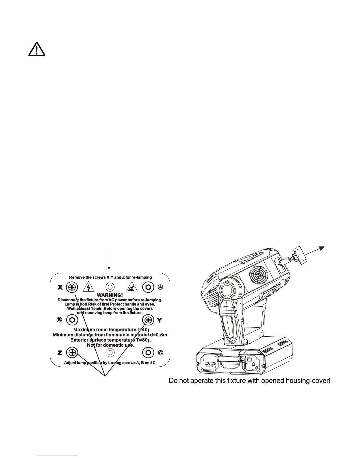
Lamp Installation
1. Physically disconnect fixture from power mains.
2. Locate the Lamp Cover. Do not proceed until the Lamp Cover is cool to touch.
3. Remove the 3 fastening screws labeled X, Y and Z.
4. Carefully draw out Lamp Cover and lamp. Remove old lamp (if installed). Never
handle lamps with bare hands. Dispose of lamp properly.
amp cover
3 phillips screws "X,Y,Z"
5. Insert new lamp into socket. Ensure lamp is properly seated.
6. Carefully replace Lamp Cover and lamp. Ensure that lamp wires are not pinched or in
contact with the lamp when the Lamp Cover is fully installed.
7. Replace the 3 fastening screws labeled X, Y and Z.
10
Page 11

Lamp Alignment
Due to slight variations between lamps it may be necessary to perform fine adjustments
to remove excessively dark or bright spots in the output field. The lamp holder is aligned
at the factory, large adjustments to the alignment will not be necessary. Excessively
bright spots can damage optical components.
1. Apply power to the fixture.
2. Using a controller, strike the lamp with
shutter and dimmer to 100% and project
an open white beam on a flat neutral
colored surface.
3. Center the bright spot of the beam using
the Adjustment Screws A, B and C.
4. After centering the bright spot of the
beam, turn each Adjustment screw ¼ turn
either all clock wise or all counter clock
wise until the projected beam is as evenly
bright as possible.
3 adjustment screws "A,B,C"
Mounting
Always consult a qualified professional when rigging. This fixture may be placed on any flat
surface or truss that is capable of safely supporting the weight. When selecting a mounting
position, take into consideration access for routine maintenance. This fixture may be mounted in
any position provided there is adequate room for movement and ventilation. Mount the fixture
securely using two mounting clamps and a safety cable. An Eye Bolt is provided for safety
attachment. Safety cables must always be attached to the fixture. Do not use handles as
secondary mounting points. Do not mount in a place where the fixture will be exposed to rain,
high humidity, extreme temperature changes or restricted ventilation. Do not obstruct the vents
or fans. Keep fixture a minimum of 3.3ft (1m) from flammable materials.
11
Page 12

Data Link DMX-512
DMX-IN
X
Ω
For data, this fixture uses 3 pin XLR (Cannon) type connectors and shielded twisted pair cable
approved for EIA-422/EIA485 use. Fixtures are connected in Daisy Chain topography with only
one data source and no branching is allowed. Systems using 5 pin DMX interfaces can be
accommodated by purchasing 3-to-5 pin adapters or building adapter cables.
XLR Connector - Socket:
DMX512
Data Terminator
A Data Terminator can be connected to the DATA OUT connection
of the last fixture to reduce the effects of noise in the signal; it is not
required for all installations. To make a Data Terminator, connect a
120-ohm ¼ watt resistor across pin 2, Data Negative (S-) and pin 3,
Data positive (S+). A qualified technician can determine if a Data
Terminator is needed.
Adapter 5-to-3 pin
Numbers designating each pin can be found on connectors. Converting between the two
XLR types is done in a pin-to-pin fashion. Connect the shields to pin 1, then connect pin
2 to pin 2 and pin 3 to pin 3. This is true for converting either 5 to 3 pin or 3 to 5 pin
regardless of either connector’s gender. Pins 4 and 5 are not used on the 5 pin XLR
connectors.
5 Pin XLR (Socket)
Pin 1: GND(Sheild)
Pin 2: Signal(-)
Pin 3: Signal(+)
Pin 4: N/C
Pin 5: N/C
DMX-OUT
1
- Ground
2
- Signal (-)
3
- Signal (+)
LR Connector - Plug:
1
- Ground
2
- Signal (-)
3
- Signal (+)
120
3 XLR (Plug)
Pin
Pin 1: GND(Sheild)
Pin 2: Signal(-)
Pin 3: Signal(+)
3 XLR (S )
Pin ocket
Pin 1: GND(Sheild)
Pin 2: Signal(-)
Pin 3: Signal(+)
12
5Pin XLR (Plug)
Pin 1: GND(Sheild)
Pin 2: Signal(-)
Pin 3: Signal(+)
Pin 4: N/C
Pin 5: N/C
Page 13

Control Panel Menu
Use the fixture’s Control Panel to access the Control Menu. The MODE Key moves between
options, UP/DOWN selects the Action of the option and ENTER confirms the selection. Settings
are stored and recalled on subsequent power cycles.
Mode
Function
Pan movement direction Invert
Tilt movement direction Invert
DMX Start Address
Fixture Reset
Color Wheel Movement Mode
Operating Mode
Lamp ON/OFF
Action
NO = Not Invert ed
YES = Inverted
NO = Not Invert ed
YES = Inverted
Selectable 1 to 512
NO = Default
YES = Initiate Reset
NO = Stepped Change
YES = Linear Change
= DMX-512 mode
= Automatic Demo
ON = Not Invert ed
OFF = Inverted
Start Address
The Start Address of a fixture is set using the “Addr” mode in the Control Panel Menu. Consult
the manual of the system’s DMX512 controller to select a desirable addressing scheme before
addressing fixtures. Each fixture connected to the DMX-512 data link requires a Start Address
to indicate the first DMX channel containing data designated for that fixture, see DMX-512
Background. Valid Start Addresses range from 1 to 512. Fixtures requiring more than one
channel for control will read subsequent channels up to the total number of channels required.
A fixture requiring five (5) channels of DMX, set to a Start Address of eleven (11), would read
data from channels: 11 and 12, 13, 14, 15. The next logical Start Address would be channel
16. Because all fixtures see the same data, fixtures may be set to any address without concern
to order in the DMX-512 chain or physical location. Choose a Start Address so the channels
used do not overlap with other fixtures. In some cases, it may be desirable to set two or more
same type fixtures to the same Start Address. In this case, the fixtures will be slaved together
and respond to the same data.
Example Select Start Addresses for 4 fixtures each requiring 16 channels of DMX.
Since these are the first fixtures added to the system, the first unit will be set to Start
Address=1. This fixture occupies DMX channels 1 thru 16. The next DMX channel
available for a Start Address is found by adding the previous fixture’s Start Address to its
channel requirement: 1+16=17. DMX channel 17 is the next available Start Address. In
this example, to maximize channel usage no empty channels are left between fixtures so
the second Start Address is set to DMX channel 17. The second fixture occupies DMX
channels 17 thru 32. Repeat the process for the remaining two fixtures: 17+16=33 and
33+16=49. Therefore, the four 16 channel fixtures have Start Addresses of 1, 17, 33 and
49. Repeat the technique once more for the next free channel in the system, 49+16=65.
Channels 65 thru 512 are available for expansion of the system.
13
Page 14

DMX-512 Channels
The Tracker 575 Wash requires 16 channels of DMX.
Channel Function
1 Pan Coarse Movement
2 Pan Fine Movement
3 Tilt Coarse Movement
4 Tilt Fine Movement
5 Movement Speed Pan/Tilt
6 Control Reset/Lamp
7 Fixed Color Wheel
8 Cyan Mix
9 Magenta Mix
10 Yellow Mix
11 CMY Mix Speed
12 Color Presets CMY
13 Effects
14 Zoom
15 Shutter
16 Dimmer
CH 1-4 : Pan / Tilt Movement
The Pan and Tilt motors use a position feedback system. If the position of either is
disturbed, the fixture will correct automatically. The Pan and Tilt Menu Modes can be
used to alter the default direction of movement. Movement speed is either automatically
determined by the fixture or manually set using Channel 5 Pan/Tilt Movement Speed.
Pan range is 530° of movement. Tilt range is 280° of movement.
CH 1 – Pan Coarse Movement (530°)
CH 2 – Pan Fine Movement
CH 3 – Tilt Coarse Movement (280°)
CH 4 – Tilt Fine Movement
DMX Value Function
0 – 255 Movement - Minimum to Maximum
CH 5 : Movement Speed Pan/Tilt
When set to zero (0) the fixture automatically determines the Pan/Tilt speed. Other
values are used to set the movement speed manually.
CH 5 – Movement Speed Pan/Tilt
DMX Value Function
0 Auto Speed
1-255 Fixed Speed - Fast to Slow
14
Page 15

CH 6 : Control Reset/Lamp
Fixture reset and Lamp On/Off control is accessed from a single channel. The “No
Function” values provide buffer zones between functions and are not values to which the
channel should be set. In the case of noisy faders or unintentional movement, the buffers
will prevent slight variations in value to toggle Lamp states or start a fixture Reset.
CH 6 – Control Reset/Lamp
DMX Value Function
0-127 No Function
128-139 RESET then Lamp ON (3 second delay)
140-229 No Function
230-239 Lamp OFF (3 second delay)
240-255 No Function
CH 7 : Fixed Color Wheel
The Fixed Color Wheel holds 4 solid colors, 2 color correctors (CTO and CTB) and a UV
effect filter. These color filters can be used in conjunction with the CMY color mixing to
create many color combinations.
CH 7 – Fixed Color Wheel
DMX Value Function
0-24 Open
25-49 Red
50-74 Blue
75-99 Green
100-124 Orange
125-149 CTO Color Temperature Shift Down (Orange)
150-174 CTB Color Temperature Shift Up (Blue)
175-199 UV Effect
200-255 Color Rainbow effect Slow to Fast
15
Page 16

CH 8 : Cyan Mix
Controls the saturation of the Cyan in the CMY color mixing system. This can be used in
conjunction with the other CMY channels and the Fixed Color Wheel to create many color
combinations.
CH 8 – Cyan Mix
DMX Value Function
0-255 Cyan Saturation - Least to Most
CH 9 : Magenta Mix
Controls the saturation of the Magenta in the CMY color mixing system. This can be
used in conjunction with the other CMY channels and the Fixed Color Wheel to create
many color combinations.
CH 9 – Magenta Mix
DMX Value Function
0-255 Magenta Saturation - Least to Most
CH 10 : Yellow Mix
Controls the saturation of the Yellow in the CMY color mixing system. This can be used
in conjunction with the other CMY channels and the Fixed Color Wheel to create many
color combinations.
CH 10 – Yellow Mix
DMX Value Function
0-255 Yellow Saturation - Least to Most
CH 11 : CMY Mix Speed
Controls the speed of all three CMY flags in the color mixing system.
CH 11 – CMY Mix Speed
DMX Value Function
0-255 Color Mix Speed - Fast to Slow
16
Page 17

CH 12 : Color Presets CMY
Selects one of 18 preset mixes of the Cyan, Magenta and Yellow. This channel will
override the CMY channels 8, 9 and 10.
CH 12 – Color Preset CMY
DMX Value Function
0-7 None (CMY under independent control)
8-13 Open (CMY channels 8, 9 & 10 values set to “0”)
14-27 Color Preset 1
28-41 Color Preset 2
42-55 Color Preset 3
56-69 Color Preset 4
70-83 Color Preset 5
84-97 Color Preset 6
98-111 Color Preset 7
112-125 Color Preset 8
126-139 Color Preset 9
140-153 Color Preset 10
154-167 Color Preset 11
168-181 Color Preset 12
182-195 Color Preset 13
196-209 Color Preset 14
210-223 Color Preset 15
224-237 Color Preset 16
238-251 Color Preset 17
252-255 Color Preset 18
CH 13 : Effects
The standard projection from this fixture is a round soft edge beam. Modification of the
beam can be done with either a Frost Effect, creating a very wide diffused edge or with
the Beam Shape Effect (Lenticular), creating an oblong beam that can be rotationally
adjusted 180° on axis.
CH 13 – Effects
DMX Value Function
0-49 Open
50-99 Frost
100-255 Beam Shape - 0° to 180°
CH 14 : Zoom
Beam angle can be varied continuously from 7° to 28°.
CH 14 – Zoom
DMX Value Function
0-255 Beam Angle - Wide 28° to Narrow 7°
17
Page 18

CH 15 : Shutter
The Shutter functions in three modes. Standard Strobe Effect where the shutter
Opens/Closes at a fixed rate. Pulse Strobe Effect where the Open and Close speeds are
different. Random Strobe Effect runs the shutter at irregular intervals.
CH 15 – Shutter
DMX Value Function
0-31 Closed (Black Out)
32-63 Open
64-95 Strobe Effect - Slow to Fast
96-127 Open
128-131 Pause
132-159 Pulse Strobe Effect - Slow to Fast
160-191 Open
192-223 Random Strobe Effect
224-255 Open
CH 16 : Dimmer
The dimmer is used to vary the intensity of the beam from full open to dark.
CH 16 – Dimmer
DMX Value Function
0-255 Intensity - Dark to Full Open
18
Page 19
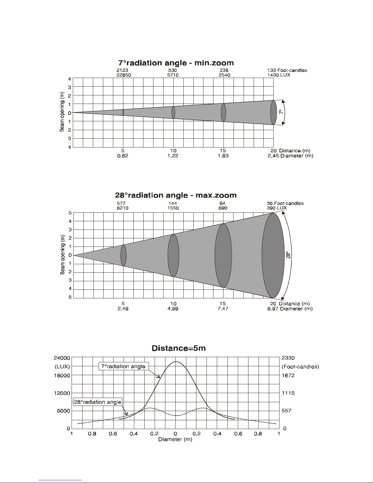
Photometric Charts
19
Page 20

DMX-512 Background
DMX-512 is a digital data transmission standard developed by the United States Institute for
Theater Technology (USITT). It is designed to enable control of lighting equipment, originally
dimmers. DMX deals solely with the formatting of data for transmission and does not dictate
how the data is created or used.
Under DMX, signals are transmitted in much the same way a computer modem transmits data.
The Data, divided in to channels, is "Framed" using a start bit, high (1), eight data bits and
finally, two stop bits, both high (1). DMX uses no parity to check the integrity of the signal.
Instead, DMX relies on the ultra low probability of an error occurring in the same place when the
data is resent. The rate at which data is sent is fixed at 250k bps, almost four and a half times
faster that a 56k modem. This speed allows all data on a DMX chain to be updated more than
44 times every second.
The transmitted data follows a specific format. DMX allows for 512 channels each with eight
data bits, giving each channel the possibility of 256 values. When a data "Packet" is sent, all
channels are transmitted one after another. Even if the data on a specific channel has not been
changed, it must be sent. In a packet, a "start code" of all zeros is sent before the data to
identify the signal as a Standard DMX transmission. This start code is transparent to the user
and is handled by the controller.
The physical signals are transmitted using a twisted pair of wires and a common shield, a
configuration called Balanced. The controller and all receiving equipment are connected using a
“Daisy Chain" connection. The signal is jumped from the controller to a piece of DMX
equipment. From there, the signal is jumped to the next piece of equipment and so on until the
last piece of equipment is connected. No branches are allowed and the signal does not come
back to the controller. The final piece of equipment will have only one cable connection. As a
result, all equipment connected to the chain will see exactly the same signal whether it is first or
last. When connecting equipment, no particular attention needs to be paid to the order in which
the equipment is connected. Depending on the conditions and equipment, a line terminator may
be required. If there is any question, in most circumstances the addition of a terminator will not
degrade the signal. To make a terminator, add a 120-ohm resistor between the Signal Data
Negative and Signal Data Positive pins of a connector in the last piece of equipment in the
chain.
The DMX Standard calls for connections between DMX compatible equipment to be made using
5 pin XLR connectors. However, it is common to see fixtures with 3 pin XLR connectors as
these types of balanced or “Lo-Z” cables are common in the audio industry. In either case, pin
numbers are the same and carry the same signals.
Pin 1 - Signal Common (Shield)
Pin 2 - Signal Data Negative
Pin 3 - Signal Data Positive
Pin 4 - (not used)
Pin 5 - (not used)
20
Page 21

Maintenance
Make sure fixture is cool and disconnected from power mains before any service.
Do not touch the lamp glass with bare fingers. Wear eye protection when handling lamp
Weekly operating hours and environmental conditions will establish how often the fixtures need
cleaning. Fixtures should be cleaned and inspected at least once a month to maintain optimum
performance. Accumulation of dust and fog residue increases heat build up, can lead to
malfunctions, overheating and reduction in maximum light output. This condition may cause
undue stress on electronics, mechanical elements, reduce lamp life, fixture life and over all
performance. Before conducting any maintenance, disconnect fixture from power mains.
1) Disconnect fixture from power mains.
2) Use a vacuum with a soft brush to remove dust collected on external vents and internal
components. If using an air compressor, use low pressures and extreme care to prevent
damaging any internal parts or effects.
3) Vacuum dust buildup from fan intakes and check that all fans function correctly.
4) Clean all optical elements when the fixture is cold. Use a soft lint free cotton cloth or tissue
and either Isopropyl or Denatured Alcohol. Any cleaner approved for coated eyeglass lenses
will also work.
5) Inspect clamps and safety cables to ensure fixture is secure and safe.
21
Page 22

Troubleshooting
Symptom Possible Cause / Solution
No Power
Check for power on mains
Check power switch
Check main fuse and fuse holder
No response to DMX
Incorrectly responds to DMX
(Diagnostic technique for DMX issues: Set
suspect fixture’s Start Address the same as a
correctly functioning fixture. If both units then
function correctly, issue is programming)
No Lamp Power
Erratic operation
An effect wheel doesn’t go to correct position
Check data cables
Check Start Address
Check that fixture isn’t in the Demo mode
Check Start Address
Check for overlapping addresses
Check fixture set up (Pan/Tilt Invert…)
Check Data cables (faults and proper wiring)
Bad or end of life lamp
Check DMX value for Control/Reset Lamp
Channel
Inspect fixture light path and verify no effects
are blocking beam
Remove from DMX and check to see if lamp
can be struck from Control Panel
Over temperature error – Tun Lamp off and
allow fixture to cool then attempt to restrike
the lamp. If this is the case, check all fans.
See “Incorrectly responds to DMX”
Check for properly wired DMX cables
Check for broken wires inside unit
Check for damaged Data transceiver IC.
Check sensor and magnet
Check belts (if applicable)
Check motor with no power, should be able
to move easily.
22
Page 23
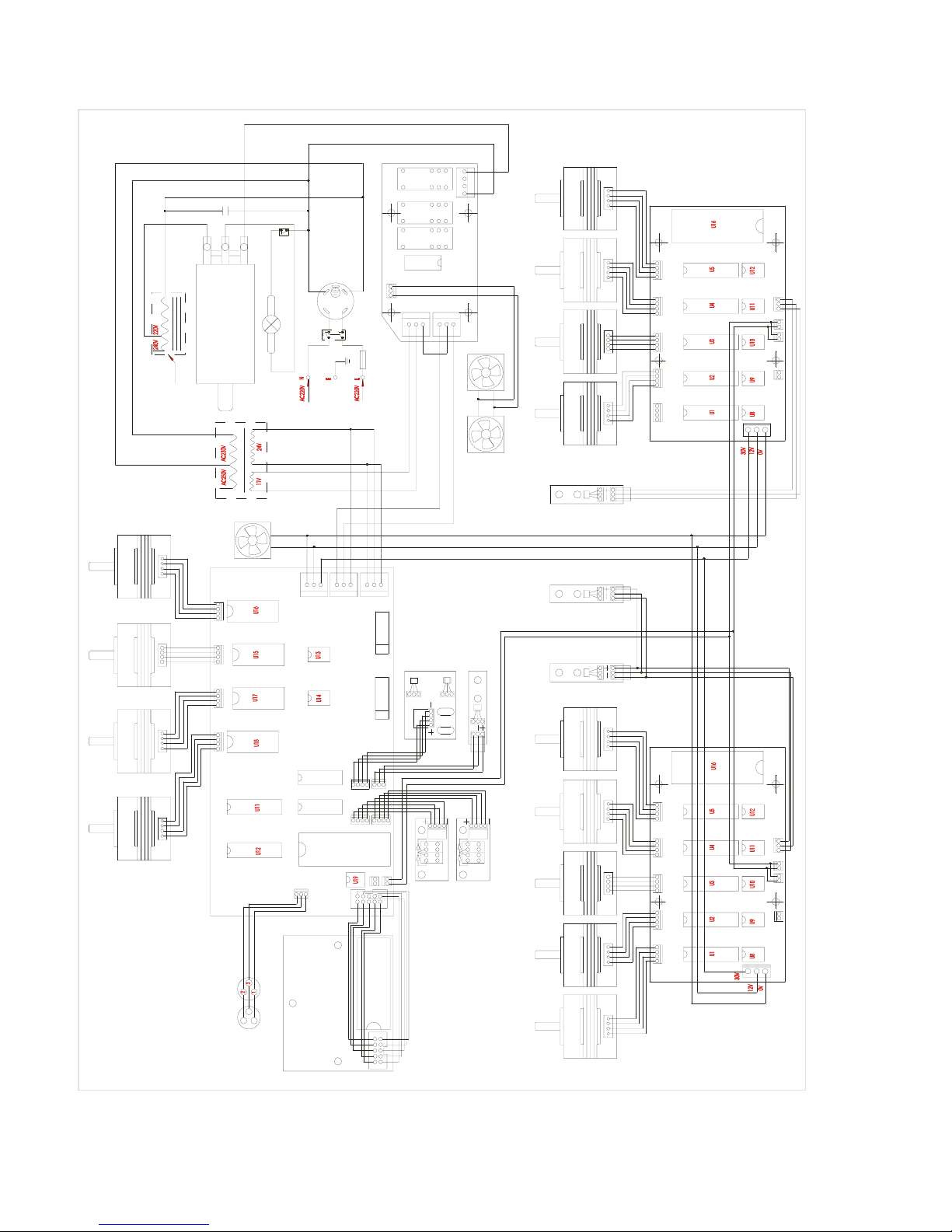
Wiring Diagram
COLOR WHEEL
POWER SUPPLY
TEMPERATURE
SWITCH
FILTER
PROTECTION
BOARD
IGNITER
BALLLEST
CYAN
MAGENTA
YELLOW
COLOR WHEEL
SENSOR
2106R
Fan
PAN 1PAN 2
RIPPLE LENS SENSOR
PAN
SENSOR
TILT
SENSOR
SPIRAL LENS
(ZOOM)SENSOR
MAIN PCB
RIPPLE LENS
TILT 2 TILT 1
DISPLAY BOARD
DIMMER STROBE
PAN
ENCODER
SENSOR
TILT
ENCODER
SENSOR
SPIRAL LENS 1 SPIRAL LENS 2
2106L
23
Page 24

Accessory Items
Order Code Description
LCSR575/2SE-G Replacement Lamp GE CSR575/2, 575w, 1000 Hours, 7200K
LMSR575/2-P Replacement Lamp Phillips MSR575/2, 575w, 1000 Hours, 7200K
CLAMP-MEGA/B Clamp-Mega Black - Heavy Duty
CLAMP-CBHALF Coupler Half Cheeseborough
SAFETYCABLE1 Safety Cable Silver 30”
SAFETYCABLE2 Safety Cable Black 30”
SAFETYCABLE3 Safety Cable Black 18”
SAFETYCABLE4 Safety Cable Silver 18”
CA-XLR3/1 Pre-made 1’ 3-pin XLR Cable
CA-XLR3/5 Pre-made 5’ 3-pin XLR Cable
CA-XLR3/10 Pre-made 10’ 3-pin XLR Cable
CA-XLR3/20 Pre-made 20’ 3-pin XLR Cable
CA-XLR3/50 Pre-made 50’ 3-pin XLR Cable
CA-XLR3/100 Pre-made 100’ 3-pin XLR Cable
CO-XLR3M XLR Connector 3-pin Male
CO-XLR3F XLR Connector 3-pin Female
CO-XLR5M XLR Connector 5-pin Male
CO-XLR5F XLR Connector 5-pin Female
CO-XLRTERM3 XLR 3 Pin Data Terminator
CO-XLR3MTO5F XLR 3 Pin Male to 5 Pin Female Adapter
CO-XLR5MTO3F XLR 5 Pin Male to 3 Pin Female Adapter
24
 Loading...