

Page 1
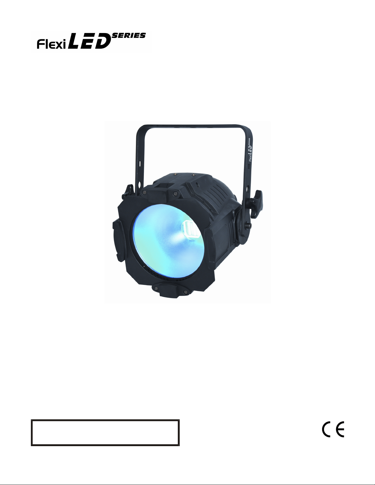
Information specifically for:
DL-FLEXILED100TC/B
This manual contains important information.
Please read before operating fixture.
V1.0
Page 2

IMPORTANT INFORMATION
Save original packing and documentation for warranty, service and return issues.
Limited Warranty: This warranty covers defects or malfunctions in this equipment. This warranty lasts
for a period of one year from date of purchase. It is the owner’s responsibility to provide invoices for
proof of purchase, purchase date and dealer or distributor. If purchase date can not be provided,
warranty period will start at manufacture date. It is the sole discretion of Techni-Lux to repair or replace
parts or equipment. All shipping will be paid by purchaser. This warranty does not cover lamps, fuses,
belts, power semiconductors, relays, cleaning, standard maintenance adjustments or normal wear items
or any problem resulting from the following: improper wiring, incorrect voltage (including low or over
voltage conditions and lightning), abuse, misuse, improper maintenance or an act of God or damage
resulting from shipping. Warranty will be null and void if the product is altered, modified, misused,
damaged, or subjected to unauthorized repairs. Lamps are covered by relevant manufacturer warranty.
This warranty gives you specific legal rights, and you may also have other rights which vary from state to
state. Any liability for consequential and incidental damages is expressly disclaimed. No other warranty,
expressed or implied is made. Techni-Lux liability in all events is limited to, and shall not exceed, the
purchase price paid.
Returning equipment and Repairs: All returns must be accompanied by a Return Merchandise
Authorization (RMA) number and sent pre-paid. Contact the dealer or Techni-Lux directly to obtain an
RMA. The RMA number must be clearly listed on the shipping label. Due care must be exercised in
packing all merchandise to be returned. All repairs must be accompanied by a written explanation of the
claimed problem or error encountered. Techni-Lux is solely responsible for determining a product’s
eligibility for coverage under warranty. If returning for consideration of credit, all accessories and
documentation, original protective material and cartons must be included and the equipment, packing
and carton must be in new resalable condition. Credit for returned merchandise will be issued at the
lowest current price and is subject to a restocking fee. No returns accepted on discontinued items.
Techni-Lux is not responsible for merchandise damaged in transit and reserves the right to refuse any
return that is damaged by the carrier, not accompanied by a Return Authorization Number (RMA#) or
sent by freight collect.
Claims: All claims must be made within seven (7) days of receipt of merchandise. Any physical damage
must be reported to carrier upon receipt of merchandise.
Please record the following information for future reference:
Model Number: DL-FLEXILED100TC/B
Serial Number: ________________________________________
Dealer: ______________________________________________
Date of Purchase: ______________________________________
www.Techni-Lux.com
2
Page 3

Table of Contents
Specifications .............................................................................................................................4
Unpacking ...................................................................................................................................5
Power...........................................................................................................................................5
Mounting .....................................................................................................................................5
Basic Reference..........................................................................................................................6
Setup and Operation Modes (LCD Display)..............................................................................6
Control Panel Menu....................................................................................................................7
DMX-512 Control.........................................................................................................................7
DMX Data Connection ..............................................................................................................8
Data Terminator ........................................................................................................................8
Adapter 5-to-3 pin .....................................................................................................................8
DMX Start Address ...................................................................................................................9
DMX Channel Assignments .......................................................................................................9
3 Channel Mode “03” ................................................................................................................9
5 Channel Mode “05” ................................................................................................................9
Channel Values and Functions – 5 Channel Mode.................................................................10
CH 1 : Red ............................................................................................................................10
CH 2 : Green.........................................................................................................................10
CH 3 : Blue............................................................................................................................10
CH 4 : Master Dimmer ..........................................................................................................10
CH 5 : Effect..........................................................................................................................10
Maintenance..............................................................................................................................11
Accessory Items (sold separately)..........................................................................................11
Troubleshooting .......................................................................................................................12
DMX-512 Background...............................................................................................................12
3
Page 4

Specifications
Fixture Overview
• RGB color mixing
• 1 x 100w COB with Red, Green, and Blue
• Beam Angle – 60°
• Rugged Aluminum Housing
• Operating modes: DMX, Static Setting, Auto Color Change, Sound Active,
Master/Slave
• Precise DMX control using 5 channels or reduced channel mode
• Two lenses included in frames, 15 and 25 degree
• Quick beam shaping using optional diffusion filters
• Digital LCD display menu for settings
• ½” Clamp mounting hole
Physical
Color Black
Size 12”W x 8.75”H x 13”L
Weight 9.5 lbs (4.32 kgs)
Housing Material Aluminum
Environmental
Location Indoor
Min. distance to flammable surface 3.3ft (1m)
Min. distance to illuminated surface 1ft (0.3m)
Electrical
Voltage Auto Ranging from 100-250vAC, 50/60Hz
Rated Power 120W
Fuses 2 amp mini size: 5.2x20mm
Control
Digital Protocol USITT DMX512 (1990)
Channels 3 and 5 maximum
Data I/O 5 Pin XLR (Cannon)
Modes DMX512 or Stand-Alone
Optics
Light Source 1 x 100w RGB COB LED
Beam Angle 60°
Rigging
Orientation Any
Mounting Points Adjustable yoke with 1/2” (13mm) mounting hole
Red, Green, and Blue
4
Page 5
Unpacking
Immediately upon receipt, carefully unpack and inspect the fixture to verify that all parts are
present and have been received in good condition. If any parts appear damaged from shipping
or the shipping carton shows signs of mishandling, notify the shipper immediately. Retain
carton and all packing material for inspection. In the event that the merchandise is to be
returned, the original carton and packing must be used. The customer will be billed for a new
carton and packing if merchandise is received without the original carton and packing.
Claims
Physical damage must be reported to the Freight Carrier or Shipping Company upon
receipt of merchandise. Damage incurred in shipping is the responsibility of the Freight
Carrier or Shipping Company. It is the customer’s obligation in the event that
merchandise is received damaged, to notify the Freight Carrier or Shipping Company
immediately. All other claims not related to damage incurred during shipping must be
made to the Dealer or Distributor within 7 days of receiving merchandise.
Returns
Returned merchandise must be in the original packing with a Return Merchandise
Authorization number (RMA) clearly listed on the shipping label. Items sent by Freight
Collect or without a RMA number will be refused. Call your sales person and request a
RMA prior to shipping. Be prepared to provide the model number, serial number and
description of the nature of the return. Shipping damage resulting from inadequate
packaging is the customer’s responsibility. Customer will be charged additional shipping
charges to return products received in non original packing and or cartons.
Power
Do not apply power to the fixture until power source is verified.
For protection against electric shock, fixture must be connected to suitable earth ground.
Make sure fixture is disconnected from power mains before any service.
The mains voltage and frequency of this fixture is automatically set. It may operate on an input
AC voltage ranging from 100 to 250volts, 50/60Hz. The listed power rating is its average
wattage under normal conditions. All fixtures must be powered directly from a switched circuit.
This fixture cannot be run on a rheostat or dimmer circuit even if used solely for a 0% to 100%
switching. Before applying power to a fixture, check that the fixture’s input voltage matches the
power source voltage. Consult a qualified electrician if there are any concerns about proper
connection to power.
Mounting
Always consult a qualified professional when rigging. Consider access for routine maintenance
when selecting a mounting position. This fixture may be mounted in any position provided there
is adequate room for movement and ventilation. Mount the fixture securely using a mounting
clamp and a safety cable. Always keep cords out of the way, thus preventing any trip hazards.
Secure all cables properly. Do not mount where the fixture will be exposed to rain, high
humidity, extreme temperature changes or restricted ventilation. Do not obstruct any vents.
5
Page 6
Basic Reference
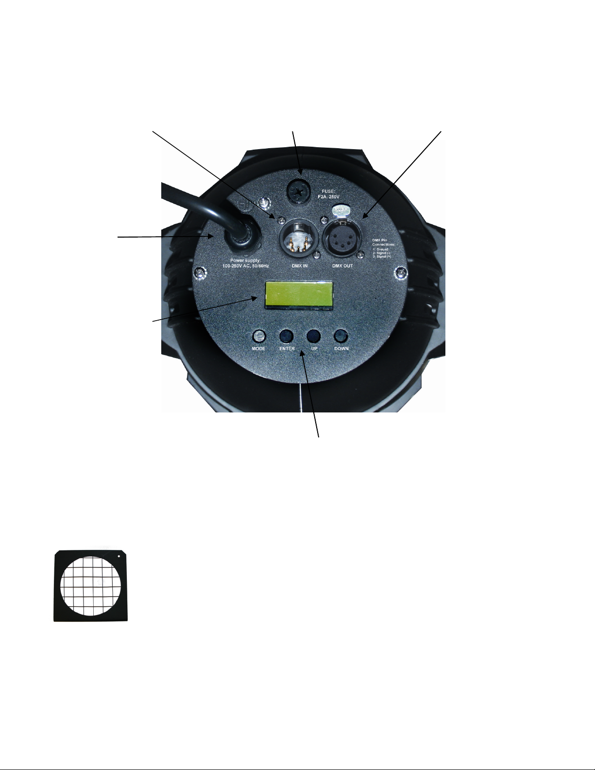
Male XLR 5-pin Data Input Fuse Holder Female XLR 5-pin Data Output
Power Input
Digital LCD Display
Menu Setting Buttons
Setup and Operation Modes (LCD Display)
This fixture includes two special lens frames: a 15 and a 25 degree. Without a
lens installed, the fixture will produce a wide 60 degree beam. The lens frames
can be used to change the output beam of the fixture. By using certain light
diffusers, it is possible to create different desired lighting effects. A desired
effect might be a softer or diffused light beam. Many diffraction materials are
available to create different beam angles with minimal light output losses.
The following refers to the different modes that are available on this fixture via the LCD Control
Panel display. All functions are selectable from the display menu located at the back of the
fixture.
Note: The actual fixture may vary from the illustrations shown in this manual.
6
Page 7
Control Panel Menu
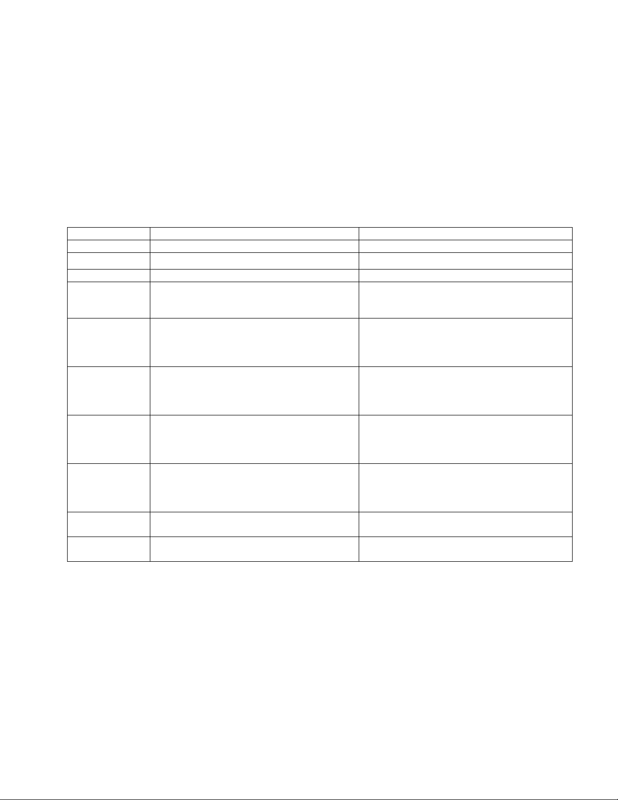
Use the fixture’s Control Panel to access the Control Menu. The MODE Key puts the
fixture in the settings menu itself and also acts as a BACK key between options,
UP/DOWN moves through the menu options and allows the assignment of a value. The
ENTER key is used to enter that option and confirms the selection once the UP/DOWN
is used to adjust the value. When in edit, the display will Flash. Settings are stored and
recalled on subsequent power cycles. R, G, B refers to Red, Green, and Blue
respectively. DMX and master/slave modes require data cables to be connected between
fixtures. Manual and some stand-alone modes do not require data cables for
independent use of the fixture. The display will shut off after 30 seconds, press any
button to relight it.
Menu Options Function Options
DMX MODE
ADDR
CHANNEL
DIMMER
CURVE
STATIC
CHANGE
CHANG3
DREAM
SOUND
MASTER/
SLAVE MODE
Note: The factory default CHANNEL MODE is set to “05” the 5 channel DMX mode.
Select DMX Start Address 01-512
Select Number of DMX Operating Channels 03 = 3 channels or 05 = 5 channels
Selects dimming curve 01 – linear response LED
Allows a static scene to be set
7 Color change scroll
3 Color change scroll
Color fading
Set audio sensitivity
Selects master or slave mode MASTER: master fixture
02 – linear response Halogen
R00G00B00 F00
set R 0-255, G 0-255, B 0-255, Flash speed
from 00 to 99
SP01-99 F00-99
Sets color change speed from 01-99
Set flash speed from 00-99
SP01-99 F00-99
Sets color change speed from 01-99
Set flash speed from 00-99
SP01-99 F00-99
Sets color change speed from 01-99
Set flash speed from 00-99
SENS:00-31
SLAVE: slave fixture
DMX-512 Control
Fixtures require a "Start Address" from 1 to 512, setting the first DMX channel containing data
for the fixture (see DMX Background). Before addressing fixtures, consult the manual of the
system’s DMX controller to select a desirable addressing scheme. Valid Start Addresses range
from 1 to 512. Fixtures requiring more than one channel for control will read subsequent
channels up to the total number of channels required. Since this fixture requires 5 channels of
DMX, if set to a Start Address of 6 it would use data from channels: 6, 7, 8, 9 and 10. Choose a
Start Address so the channels used do not overlap with other fixtures. In some cases, it may be
desirable to set two or more same type fixtures to the same Start Address. In this case, the
7
Page 8
fixtures will be slaved together and respond to the same data. Because all fixtures see the
:
T
(
)
same data, fixtures may be set to any address without concern for the order they are connected
by the DMX cables.
Note: For DMX to operate on this unit it must be set to SLAVE mode.
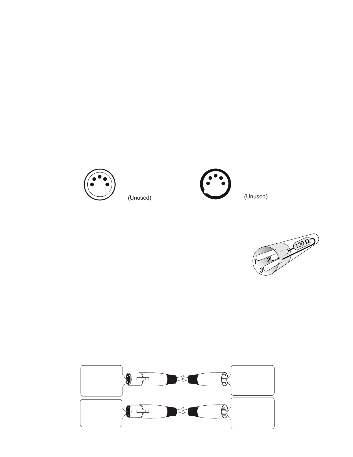
DMX Data Connection
This fixture uses 5 pin XLR type connectors and shielded twisted pair cable approved for
EIA-422/EIA485 use. Fixtures are connected in Daisy Chain topography: Connection is
made from the controller to the DMX-IN of the first light, then from the DMX-OUT to the
DMX-IN of the next light and so on. Only one data source can be on a chain and no
branching is allowed. The physical order in which the fixtures are connected is not
important, use the most convenient.
DMX-IN
XLR Connector - Plug
1
3
2
4
1
5
- Ground
2
- Signal (-)
3
-
S
ignal (+)
4
-
5
-
(Unused)
DMX-OU
XLR Connector - Socket:
1
3
4
2
5
1
- Ground
2
- Signal (-)
3
-
S
ignal
4
-
5
-
Unused
(+)
Data Terminator
A Data Terminator can be connected to the DMX-OUT of the
last fixture to reduce the effects of signal noise; it is not required
for all installations. To make a Terminator, connect a 120-ohm
¼ watt resistor across pin 2, Data Negative (S-) and pin 3, Data
positive (S+). Whether it is a 5 pin XLR or 3 pin XLR connector
(shown on right) does not matter, the pin numbers remain the
same. A qualified technician can determine if a Data Terminator
is needed.
Adapter 5-to-3 pin
Systems using 5 pin DMX interfaces can be accommodated by purchasing 3-to-5 pin
adapters or building adapter cables. Numbers designating each pin can be found on
connectors. Converting between the two XLR types is done in a pin-to-pin fashion.
Connect the shields to pin 1, then connect pin 2 to pin 2 and pin 3 to pin 3, regardless of
either connector’s gender or pin count. No connection is made to Pins 4 & 5.
5 Pin XLR (Socket)
Pin 1: GND(Sheild)
Pin 2: Signal(-)
Pin 3: Signal(+)
Pin 4: N/C
Pin 5: N/C
3 XLR (S )
Pin ocket
Pin 1: GND(Sheild)
Pin 2: Signal(-)
Pin 3: Signal(+)
3 XLR (Plug)
Pin
Pin 1: GND(Sheild)
Pin 2: Signal(-)
Pin 3: Signal(+)
5 Pin XLR (Plug)
Pin 1: GND(Sheild)
Pin 2: Signal(-)
Pin 3: Signal(+)
Pin 4: N/C
Pin 5: N/C
8
Page 9
DMX Start Address
To place the fixture in DMX mode, press the MODE key, then using the UP/DOWN keys
get to the Addr Menu Option. Press ENTER and using the UP/DOWN buttons, set the
start address number for this particular unit in the DMX chain. Once selected, press
ENTER again to save your selection. More than one fixture may have the same start
address, but they will behave the same. Giving a unique start address that does not
overlap with any other units allows you to individually control that fixture’s features fully.
Never allow channels to overlap. You will need to select the number of channels you
wish the fixture to use first. Your choices are 3 or 5 channel modes. This will determine
the spacing of channels you will need to avoid overlapping of channels when selecting
your start addresses.
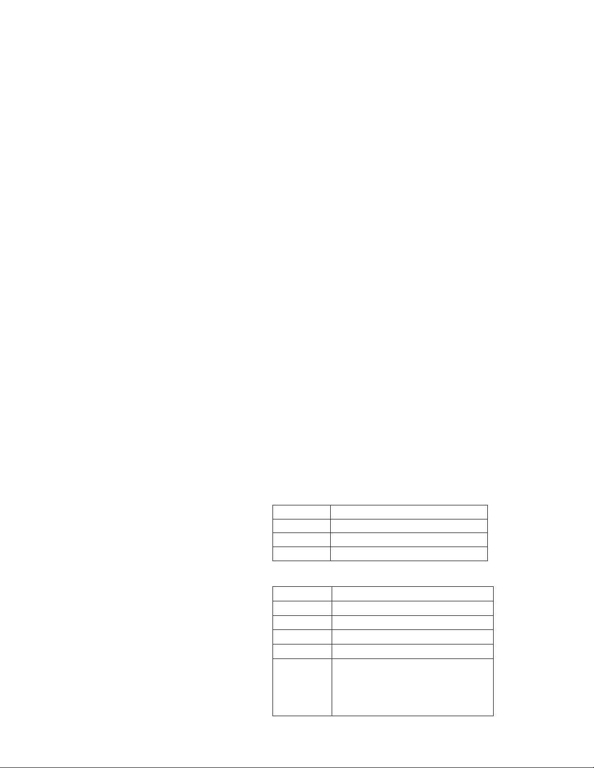
Example
channel mode).
For this example, start with the first unit set to the first possible Start Address = 1. This fixture
occupies DMX channels 1 thru 5. The next DMX channel available for a Start Address is found
by adding the previous fixture’s Start Address to its channel requirement: 1+5=6. To maximize
channel usage, we will leave no empty channels between fixtures so the second Start Address is
set to DMX channel 6 and that fixture occupies channels 6 thru 10. The third fixture will be
addressed 6+5=11 and occupy channels 11 thru 15. The last fixture is addressed 11+5=16 and
will occupy channels 16 thru 20. Thus, 4 fixtures using 5 channels each have Start Addresses of
1, 6, 11 and 16 and the next free channel in the system is 16+5=21.
Select Start Addresses for 4 fixtures each requiring 5 channels of DMX (5
DMX Channel Assignments
This fixture features 2 different DMX Channel modes. A 3 and 5 channel mode. Using
the 5 channel mode provides the most features, however it takes up the most channels
of DMX. The different channel assignments are shown below. The factory default is the
5 channel mode “05”. We will provide a full description of the values and functions of
the 5 channel mode only. All other modes of less channels, do the same functions
described within the 5 channel mode. Note that the channel order maybe different for
each of the modes.
3 Channel Mode “03”
5 Channel Mode “05”
Channel Function
1 Red (0-255)
2 Green (0-255)
3 Blue (0-255)
Channel Function
1 Red (0-255)
2 Green (0-255)
3 Blue (0-255)
4 Master Dimmer (0-255)
5 00 On
001-005 Sound Control
006-010 On
011-255 Strobe Flash Speed
9
Page 10
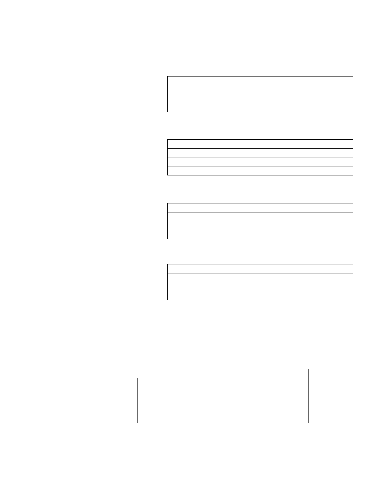
Channel Values and Functions – 5 Channel Mode
CH 1 : Red
Sets relative intensity of Red.
Actual value is subject to Master
Dimmer channels. The Color
Macro/Scroll Channel will
override this channel.
CH 1 – Red
DMX Value Function
0 No Output
1-255 Intensity - Off to Full On
CH 2 : Green
Sets relative intensity of Green.
Actual value is subject to Master
Dimmer channels. The Color
Macro/Scroll Channel will
override this channel.
CH 2 – Green
DMX Value Function
0 No Output
1-255 Intensity - Off to Full On
CH 3 : Blue
Sets relative intensity of Blue.
Actual value is subject to Master
Dimmer channels. The Color
Macro/Scroll Channel will
override this channel.
CH 3 – Blue
DMX Value Function
0 No Output
1-255 Intensity - Off to Full On
CH 4 : Master Dimmer
The Master Dimmer controls the
actual output level while the
relative level of each color is set
by the R, G, or B channels.
CH 4 – Master Dimmer
DMX Value Function
0 Black Out
1-255 Intensity - Dark to Full Brightness
CH 5 : Effect
The effect DMX channel selects between normal, sound activation or strobe flashing
operation. The strobe effect will toggle the Master Level between Off and its present
value.
CH 5 – Effect
DMX Value Function
00 Normal - no effect
001-005 Sound Control On – 7 colors
006-010 Normal - no effect
011-255 Strobe Flash Effect - Slow to Fast
10
Page 11
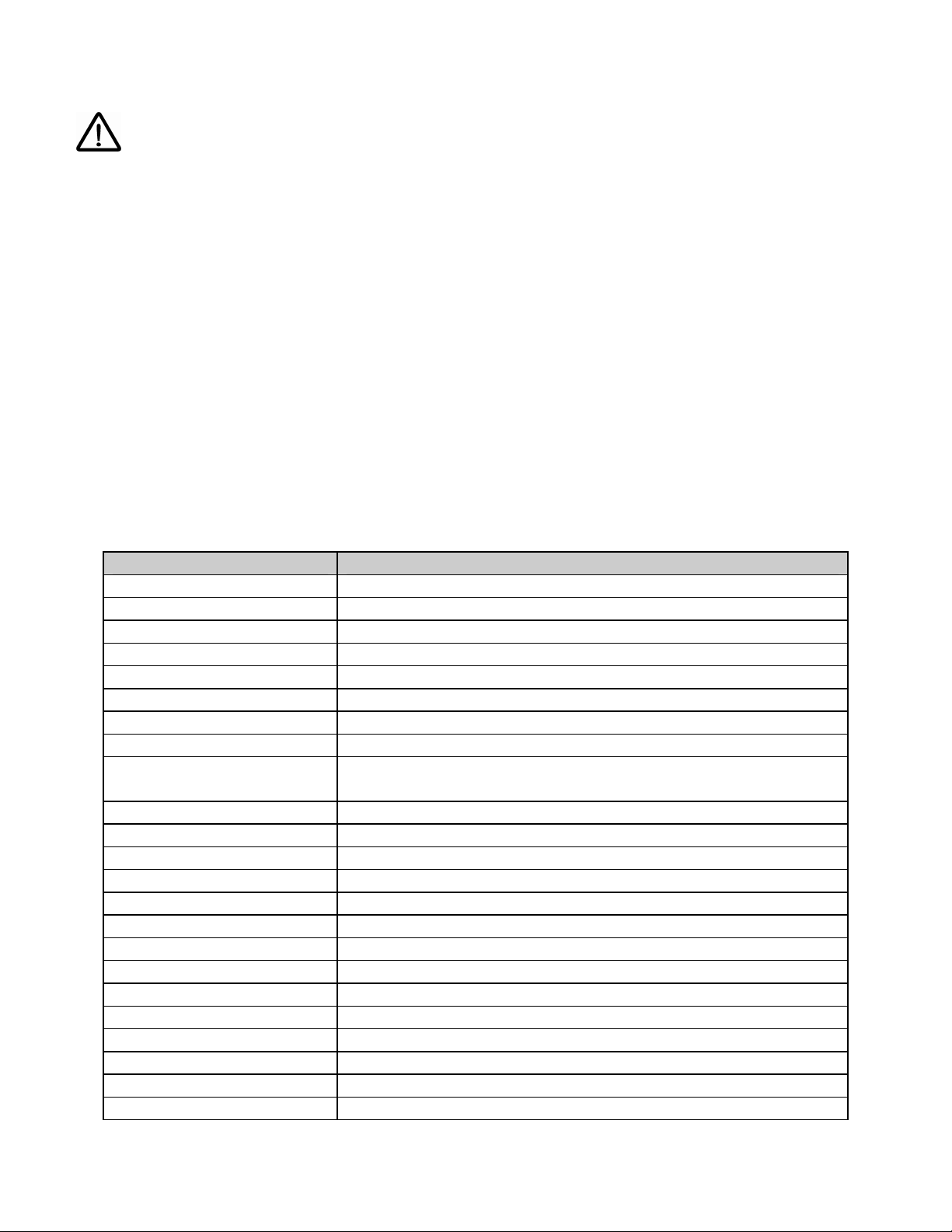
Maintenance
Make sure fixture is cool and disconnected from power mains before any service.
Weekly operating hours and environmental conditions will establish how often the fixtures need
cleaning. Fixtures should be cleaned and inspected at least once a month to maintain optimum
performance. Accumulation of dust and fog residue increases heat build up, can lead to
malfunctions, overheating and reduction in maximum light output, reduced fixture life and over
all performance. Before conducting any maintenance, disconnect fixture from power mains.
1) Disconnect fixture from power mains.
2) Use a vacuum with a soft brush to remove dust collected on external vents and internal
components. If using an air compressor, use low pressures and extreme care to prevent
damaging any internal parts or effects.
3) Clean all optical elements when the fixture is cold. Use a soft lint free cotton cloth or tissue
and cleaner safe for plastics.
4) Inspect clamps and safety cables to ensure fixture is secure and safe.
Accessory Items
Order Code Description
CLAMP-MEGA/B Mega Heavy Duty Aluminum Clamp – Black
CLAMP-CBHALF Half Cheeseborough Coupler 300kg Max Load
SAFETYCABLE18B Safety Cable Black 18”
SAFETYCABLE18S Safety Cable Silver 18”
TA-BDRFLEXI/B 4-Leaf Barndoors
UG-LSD1010 – 100100 Various light diffuser options - 10x10, 10x30, 20x20,
CA-XLR5/5 Pre-made 5’ 5-pin XLR Cable
CA-XLR5/10 Pre-made 10’ 5-pin XLR Cable
CA-XLR5/25 Pre-made 25’ 5-pin XLR Cable
CA-XLR5/50 Pre-made 50’ 5-pin XLR Cable
CA-XLR5/100 Pre-made 100’ 5-pin XLR Cable
CO-XLR5M XLR Connector 5-pin Male
CO-XLR5F XLR Connector 5-pin Female
CO-XLRTERM5 XLR 5 Pin Data Terminator
CO-XLR3MTO5F XLR 3 Pin Male to 5 Pin Female Adapter
CO-XLR5MTO3F XLR 5 Pin Male to 3 Pin Female Adapter
(sold separately)
30x30, 40x40, 60x01, 60x60, 100x100
11
Page 12
Troubleshooting
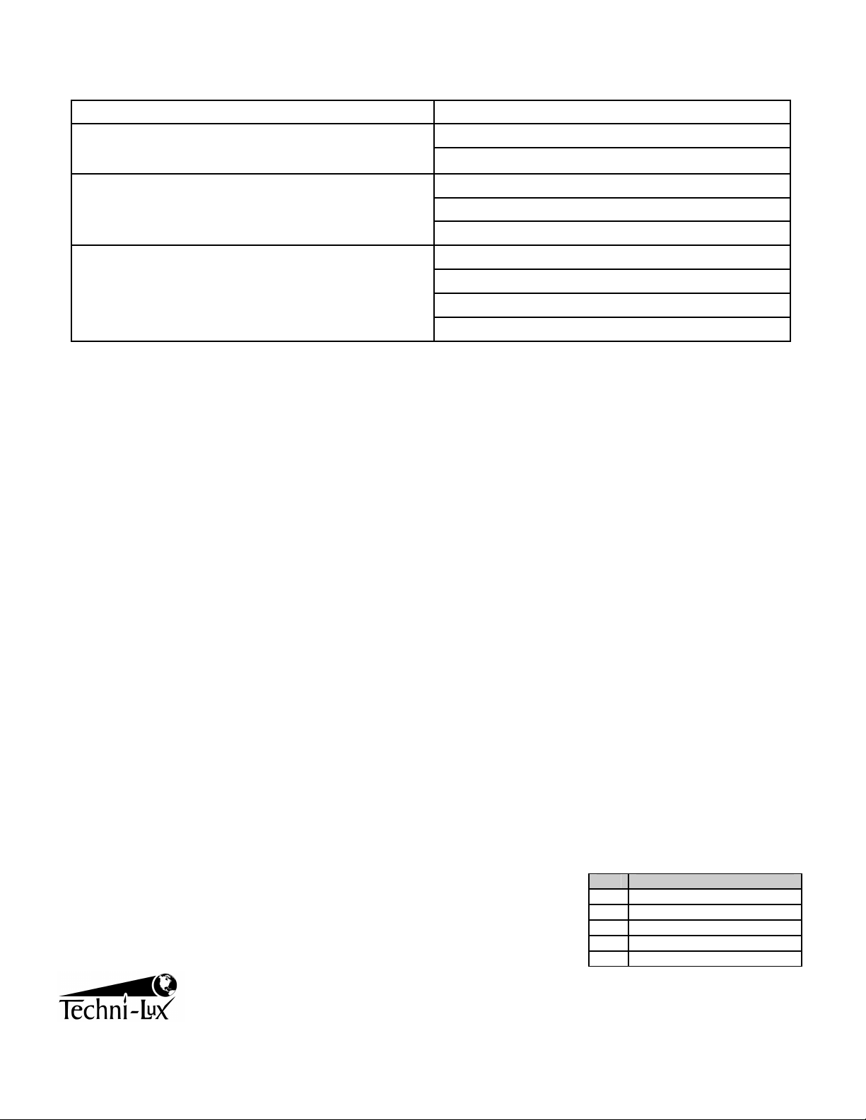
Symptom Possible Cause / Solution
Check for power on mains No Power
Check main fuse and fuse holder
Erratic / No response to DMX
Check data cables: connection and proper wiring
Check Display settings
Check Start Address
Incorrectly responds to DMX
(Diagnostic technique for DMX issues: Set
suspect fixture’s Start Address the same as a
correctly functioning fixture. If both units then
function correctly, issue is programming)
Check Start Address
Check for overlapping addresses
Check Menu settings
Check Data cables (faults and proper wiring)
DMX-512 Background
DMX-512 is a digital data transmission standard developed by the United States Institute for Theater Technology
(USITT). It is designed to enable control of lighting equipment. DMX deals solely with the formatting of data for
transmission and does not dictate how the data is created or used.
Under DMX, signals are transmitted in much the same way a computer modem transmits data. The Data, divided
into channels, is "Framed" using a start bit, high (1), eight data bits and finally, two stop bits, both high (1). DMX
uses no parity to check the integrity of the signal. Instead, DMX relies on the ultra low probability of an error
occurring in the same place when the data is resent. The rate at which data is sent is fixed at 250k bps, almost four
and a half times faster that a 56k modem. This speed allows all data on a DMX chain to be updated more than 44
times every second.
The transmitted data follows a specific format. DMX allows for 512 channels each with eight data bits, giving each
channel the possibility of 256 values. When a data "Packet" is sent, all channels are transmitted one after another.
Even if the data on a specific channel has not been changed, it must be sent. In a packet, a "start code" of all zeros
is sent before the data to identify the signal as a Standard DMX transmission. This start code is transparent to the
user and is handled by the controller.
The physical signals are transmitted using a twisted pair of wires and a common shield, a configuration called
Balanced. The controller and all receiving equipment are connected using a “Daisy Chain" connection. The signal
is jumped from the controller to a piece of DMX equipment. From there, the signal is jumped to the next piece of
equipment and so on until the last piece of equipment is connected. No branches are allowed and the signal does
not come back to the controller. The final piece of equipment will have only one cable connection. As a result, all
equipment connected to the chain will see exactly the same signal whether it is first or last. When connecting
equipment, no particular attention needs to be paid to the order in which the equipment is connected. Depending on
the conditions and equipment, a line terminator may be required. If there is any question, in most circumstances the
addition of a terminator will not degrade the signal. To make a terminator, attach a 120-ohm resistor between the
Signal Data Negative and Signal Data Positive pins of a connector in the last piece of equipment in the chain.
The DMX Standard uses 5 pin XLR connectors. However, it is common to see
fixtures with 3 pin XLR connectors as these types of balanced or “Lo-Z” cables
are common in the audio industry. In either case, pin numbers are the same and
carry the same signals.
www.techni-lux.com
Pin Connection
1 Common (Shield)
2 Data Negative (S- or Cold)
3 Data Positive (S+ or Hot)
4 n/c (not used)
5 n/c (not used)
12
 Loading...