

Page 1
Techniks Inc. 9930 E. 56th St. Indianapolis, IN 46236 | 800.597.3921 | www.techniksusa.com | [email protected]
EEPM MAGNETIC CHUCKS
www.techniksusa.com
OPERATIONS MANUAL
COMPLETE INSTALLATION AND TROUBLESHOOTING GUIDE
Techniks Inc. is a proud member of Techniks Tool Group.
Connect with TTG
Page 2
TABLE OF CONTENTS
Unpacking And Installation .............................................................................................................2
Controller Installation & Features ............................................................................................... 3
Controller Features .................................................................................................................... 3
Power Supply Check Procedure ........................................................................................... 3
Electrical Connections ............................................................................................................. 3
Controller-to-Chuck Connections ....................................................................................... 4
Interfacing with a CNC Machine Control .......................................................................... 4
Standard Remote Operation ........................................................................................................... 5
Powering Up The Controller ................................................................................................... 5
Magnetizing The Chuck ............................................................................................................ 5
Adjusting The Magnetic Holding Power ............................................................................ 5
Demagnetizing The Chuck ...................................................................................................... 5
Powering Down The Controller And Chuck ...................................................................... 5
Standard Remote Troubleshooting ............................................................................................. 6
Touch Screen Control Operation ...................................................................................................7
Magnetizing The Chuck .............................................................................................................7
Adjusting Holding Power ..........................................................................................................7
Demagnetizing The Chuck .......................................................................................................7
Multi-Chuck Control Setup ......................................................................................................7
One Controller For Two Chucks Setting .............................................................................7
Touch Screen Control Troubleshooting ..................................................................................... 8
Magnetic Failure ......................................................................................................................... 8
Demagnetization Failure ......................................................................................................... 8
Low Voltage ................................................................................................................................... 8
Chuck Cable Disconnected .................................................................................................... 8
Chuck Operations................................................................................................................................ 9
Safety Precautions ..................................................................................................................... 9
Controller & Induction Block Maintenance ..................................................................... 9
Part Setup ...................................................................................................................................... 9
Chuck Maintenance ..........................................................................................................................10
Weekly Maintenance ................................................................................................................10
Daily Maintenance .....................................................................................................................10
Storing The Equipment ............................................................................................................10
Disposing Of The Equipment .................................................................................................10
Frequent Troubleshooting Solutions ..........................................................................................11
NOTES & TIPS FOR OPTIMUM
PERFORMANCE
• Confirm your power supply meets the
EEPM requirements.
• Stock is of ferrous metals, or any
grade of steel and cast iron.
• Stock is of sufficient thickness and
material type.
• Smooth clean contact between the
magnetic chuck and the workpiece.
• Your results will vary depending
upon the size, shape, thickness and
material type you are holding.
ELECTRICAL NOTES
• Electricity is NOT required to maintain
magnetic holding power.
• Electricity is used only to reverse the
polarity of the alnico magnets.
• When in a magnetized state, holding
power is secure until demagnetized.
• The chuck will NOT lose holding
power in the event of a power loss.
CautionS and warningS
• To prevent injury never put any part of your body (i.e.
fingers, skin, etc) between a metal object and the chuck
surface. Do not wear rings, watches, necklaces, bracelets
etc., while operating the chuck.
• To prevent damage to the chuck and/or controller wait at
least two (2) minutes after magnetizing or demagnetizing
the a
• Always make sure the power receptacle on the chuck and
the plug on the chuck controller cable are free of moisture,
chips, and any contaminants before connecting the chuck
controller cable to the chuck. Failure to do so could result
in damage to the chuck and chuck controller.
1
Phone: (800) 597-3921 or (317) 803-8000 • Fax: (317) 803-8001
• Always verify that the controller is properly connected to
the chuck before operating the controls.
• Always replace the cap on the chuck power receptacle
when disconnecting the power cable from the chuck.
• Always use workstops when operating the chuck at a
power level lower than 8 to ensure the workpiece does not
move during machining.
• High temperatures (176˚F or above) will cause permanent
decay / loss of magnetic power. Do not operate the chuck
under high temperature conditions.
Page 3
UNPACKING AND INSTALLATION
UNPACKING THE CHUCK AND CONTROLLER
Upon receiving the equipment carefully unpack and verify the
following items were shipped with your order:
• 1 EEPM magnetic chuck
• 1 chuck controller with attached power supply cable for the chuck.
• 1 auxiliary hand-held remote & 1 touchscreen HMI remote control.
• 1 set of 4 toe clamps, and this Operations Manual.
Reminder: Review the packing list and confirm that all items listed
arrived intact and undamged. In case of damaged of missing items,
please contact Techniks immediately.
EEPM CHUCK INSTALLATION
Read this manual completely before installing the chuck and
controller. Always obey the CAUTIONS and warnings instructions
in this manual. Installation should only be carried out by qualified
personnel.
Power Requirements
208-480V/30A single phase
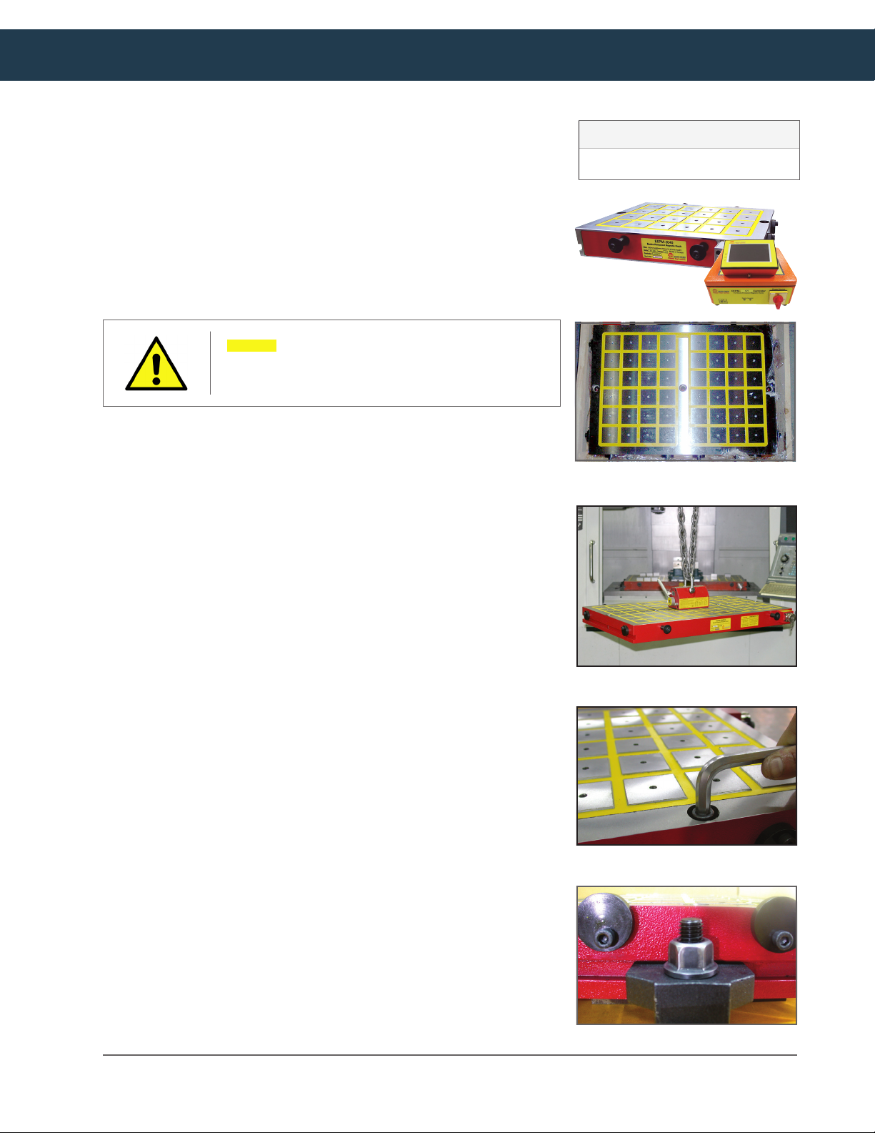
• Make sure all the EEPM components and your machine bed are
clean and dry.
• Use a Techniks EZ-Lift Lifting Magnet to safely transport the
chuck to your machine bed.
• Position the magnetic chuck on to the bed of your machining
center or pallet, securing the chuck using the supplied toe clamps
or T-slots.
FACTORS THAT AFFECT MAGNETIC HOLDING POWER
• Higher carbon content in the workpiece reduces the magnetic
attraction between the chuck and the workpiece.
• Thickness of workpiece
a) above 1-1/4” = 100%
b) 3/4” – 1-1/4” = 85%
c) 3/8” – 3/4” =50%
• Contact surface between workpiece and chuck. Chips, burrs, oil,
dirt, rough or uneven surfaces will reduce holding power.
• Contact area with the chuck. Holding power is approximately 1 ton
for every 4 poles.
transporting the EEPM chuck
Securing EEPM chuck to bed “T” slots
• Temperatures above 176˚ will reduce holding power.
Satisfaction guaranteed on all our CNC tooling solutions | www.techniksusa.com
toe clamps
2
Page 4
EEPM CONTROLLER INSTALLATION & FEATURES
5
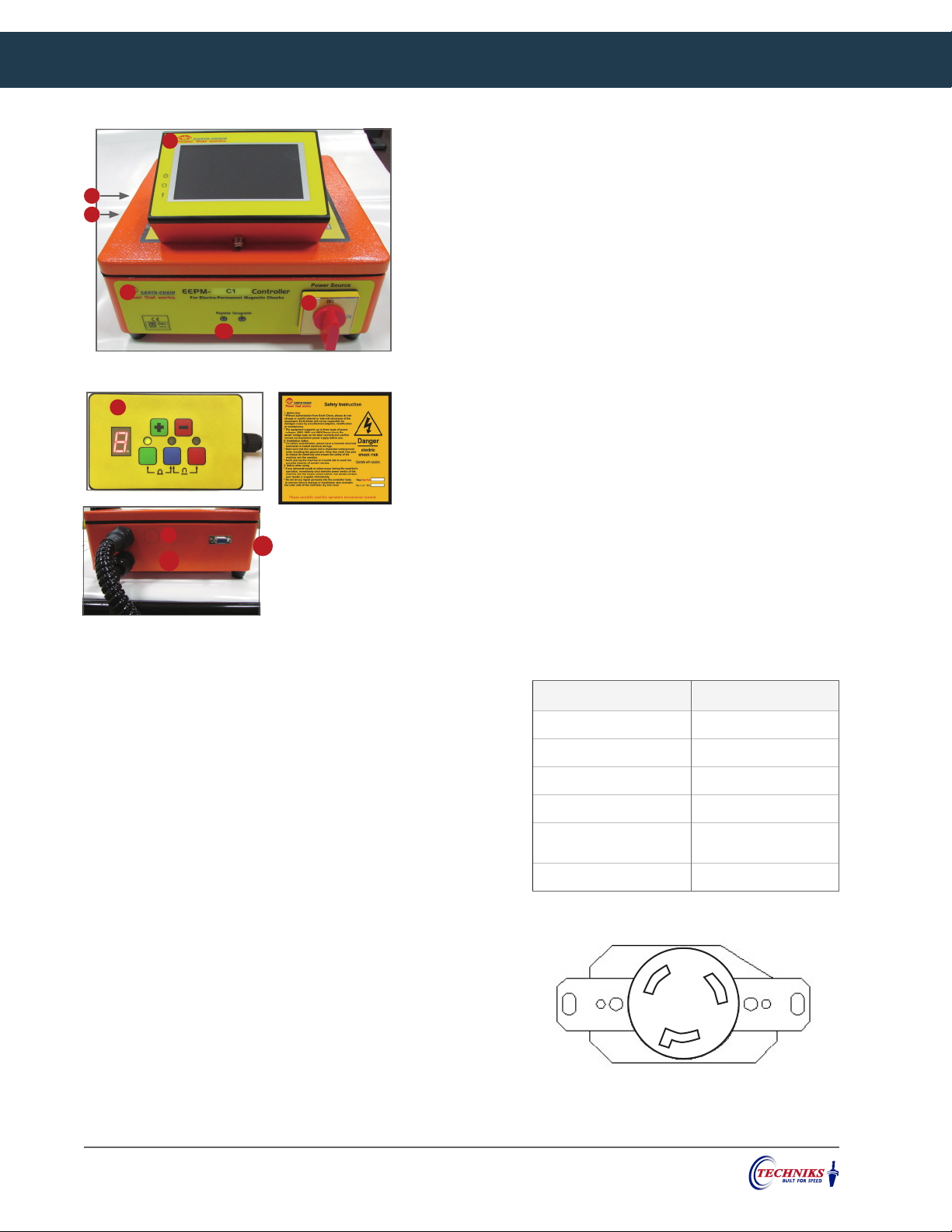
CONTROLLER FEATURES
1. Product ID: Please confirm if the product specification matches the
6
8
specification on the label and your order form after unpack.
2. Magnetize Status (Green): Light is ON, the controller is magnetized.
3. Demagnetize Status (Red): Light is ON, the controller is Demagnetized.
1
23
4
4. Power Switch: "ON" to start controller power; switch "OFF" to shut
down controller power.
5. Touch Screen Remote (HMI): For connect the controller to control
MAG., DE-MAG and adjust magnetic force level.
6. Touch Screen Remote (HMI) Port: located on side of chuck
7
7. Standard Remote
8. Standard Remote Port: located on side of chuck
9. Chuck Cable: : Connect to magnetic chuck
10. Power Cord : Connect to a power source.
9
10
Warning Sign: Please do
not open the controller
11
case due to risk of electrical shock.
Please keep this label
on the controller body
and in good condition.
11. CNC Control Port: Connect with CNC machine center. Can be used
to operate EEPM controller from CNC control.
We recommend having a certified electrician make all electrical connections and complete
the Power Supply Check (below) to ensure proper power supply and wiring connections.
POWER SUPPLY CHECK PROCEDURE
The EEPM chuck and controller must have the correct
power supply to operate safely. Have a certified electrician
test and verify that your power supply meets the power
requirements listed below. Write the actual readings in the
spaces below, and fix any problems before attempting to
install and operate your EEPM chuck.
ELECTRICAL CONNECTIONS
The chuck controller requires 208-480V/30A single phase
power. For the single phase input, the cable has three leads.
1. Connect the wires as shown in the connection diagram (right).
2 cable leads are provided for phase/neutral, and one for ground.
2. For your convenience we have installed a NEMA L8-30P plug on the
chuck controller power cord. You will need to provide a NEMA L830R receptacle. See drawing of the NEMA L8-30R.
Power Requirements ON-Site Actual
Voltage at outlet: 208 - 480V
Amperage: 30A circuit
Phase: single phase
Hertz (Hz): 60
10 gage wire from
breaker box to outlet
Dedicated circuit
NEMA L8-30R
3
Phone: (800) 597-3921 or (317) 803-8000 • Fax: (317) 803-8001
Page 5
EEPM CONTROLLER INSTALLATION & FEATURES
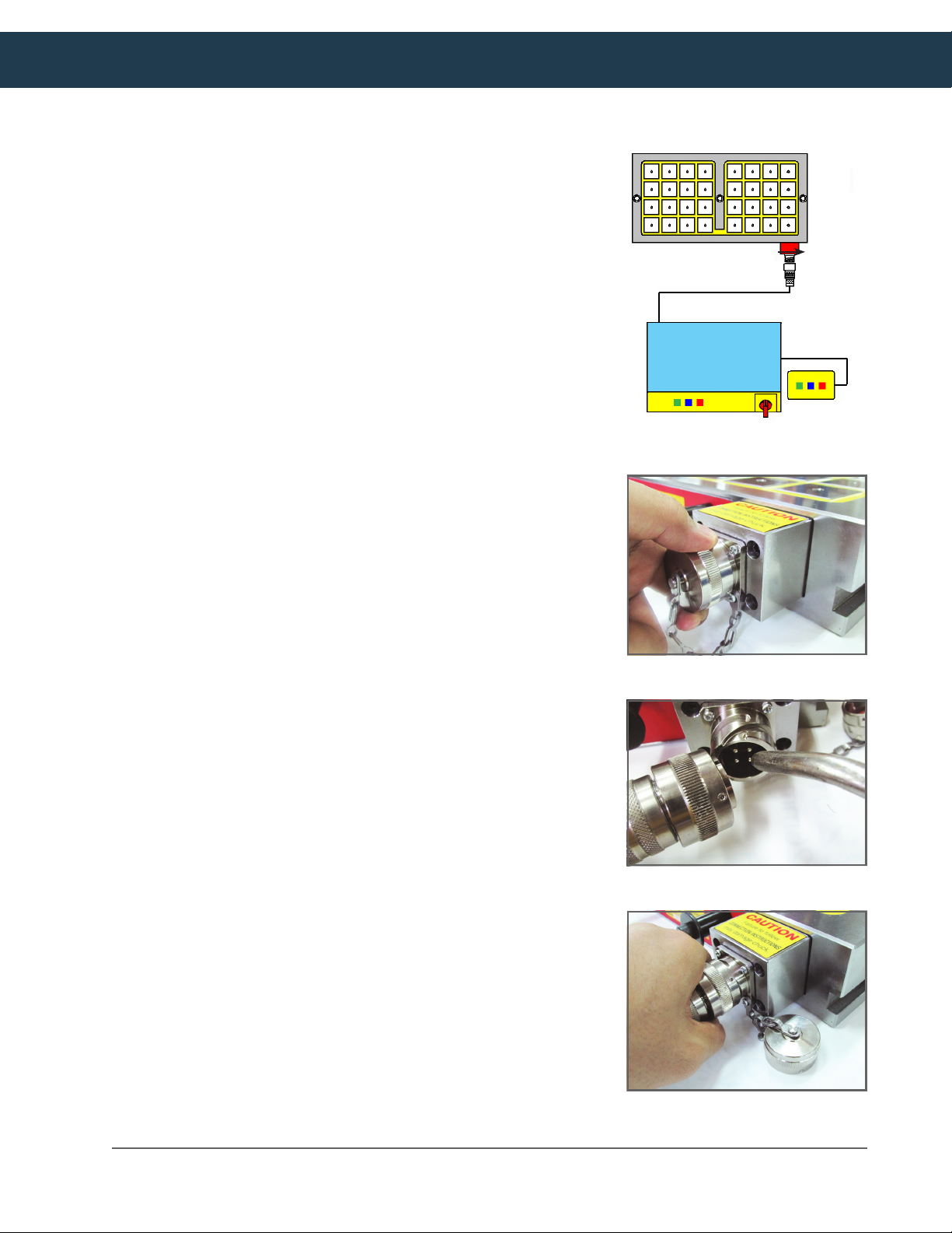
CONTROLLER-TO-CHUCK CONNECTIONS
Place the chuck controller next to the CNC machine’s control panel
in a location away from chips, oil, coolant, and any moving parts of
the machine, but near enough to the machine bed and EEPM chuck
for convenient operation.
1. Connect the chuck controller power cable to the correct power source
(208-480V/30A single phase)
2. Connect the standard or touch screen remote cable to the controller.
3. Remove the cap from the EEPM chuck power receptacle and gently spray the
with dry shop air to knock out any unseen contaminants.
4. Connect the power supply cable from the controller to the power receptacle on
the chuck. Make sure it is properly secured.
INTERFACING WITH A CNC MACHINE CONTROL
The EEPM magnetic chuck controller can interface with most CNC
controls via the 9-pin connection on the back of the controller,
allowing the magnetic chuck to be operated from the CNC control
panel.
EEPM Chuck
power receptacle
POWER CABLE
CONTROLLER
15-pin connector
REMOTE
The magnetic status of the EEPM chuck (demagnetized or
magnetized) is indicated with a set of dry contacts connected to
pins 1, 2, & 3 of the CNC control connector. When the contacts close
between 3 & 1, the chuck status is “demagnetized.” When the same
contacts are open, the chuck status is “magnetized.” The contacts
between 2 & 1 operate in reverse of 3 & 1.
To magnetize the chuck, connect the negative of an external 5-26
VDC supply to Pin 9 and connect the positive 5-26 VDC to Pin 7 for 0.8
to 1.5 seconds. To demagnetize the chuck, connect the negative of an
external 5-26 VDC supply to Pin 9 and connect the positive 5-26 VDC
to Pin 5 for 0.8 to 1.5 seconds.
The pin assignments are as follows:
Pin 1 – Status Relay COM
Pin 2 – Status Relay N.O. Chuck is magnetized
Pin 3 – Status Relay N.C. Chuck is demagnetized
Pin 5 – Demagnetize command
Pin 7 – Magnetize Command
Pin 9 – Command Negative (0V)
Satisfaction guaranteed on all our CNC tooling solutions | www.techniksusa.com
4
Page 6
STANDARD REMOTE OPERATION
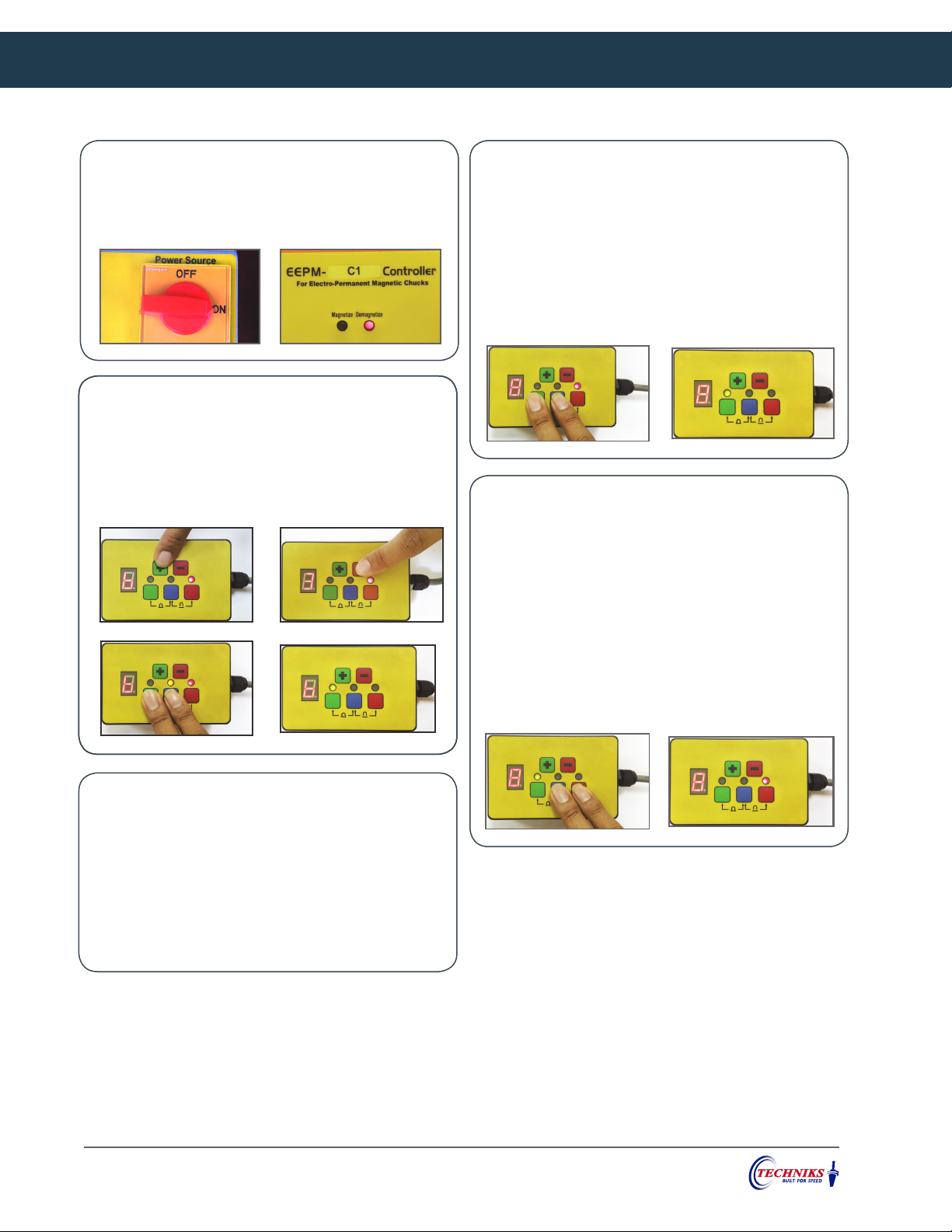
POWERING UP THE CONTROLLER
1. Turn the power switch on the chuck controller to “On”
2. Watch mag/demag light on controller is activated.
ADJUSTING THE MAGNETIC HOLDING POWER
1. Adjust the power level as needed using the + or - keys.
Magnetize the chuck and verify that it is magnetized.
3. Perform the touch test to verify that the magnetic field
is no longer strong at the surface of the workpiece.
MAGNETIZING THE CHUCK
1. Press both the blue and green buttons on the remote
simultaneously for 1 second and release.
2. Check that the green light above the green button is lit.
This indicates the chuck is magnetized (ON).
3. Perform a Touch Test to verify magnetization. With a
small ferrous object (screwdriver) you should feel a
magnetic attraction.
DEMAGNETIZING THE CHUCK
1. Press the blue and the red buttons on the remote
simultaneously for 1 second and release.
2. Check that the red light above the red button on the
chuck controller is lit. This indicates the chuck is
demagnetized (OFF).
3. Verify that the chuck is demagnetized by touching
the surface of the chuck (touch test) with a ferrous
object (screwdriver). You should not feel any magnetic
attraction as the tip of the screwdriver comes in close
proximity to the chuck surface.
POWERING DOWN THE CONTROLLER AND CHUCK
1. Demagnetize the chuck and verify it is demagnetized.
2. Turn OFF the power switch on the chuck controller.
3. Disconnect the power cable from the chuck and gently
blow out the receptacle with dry shop air to remove
any contaminants. Replace the power receptacle cap
making sure it is properly secured.
The controller has 8 power levels. Level 1 is the weakest, and 8 is strongest. We recommend using level 8 for general operation. Using
the control panel or hand-held remote, you can adjust magnetic power levels to compensate for stock thickness or to provide better
chip evacuation.
You only need to adjust the holding power if a strong magnetic field extends beyond the surface of the workpiece. This is more likely
when workpieces are under ¾” thick. Perform a touch test to determine if it is necessary to reduce the magnetic power.
5
Phone: (800) 597-3921 or (317) 803-8000 • Fax: (317) 803-8001
Page 7
STANDARD REMOTE TROUBLESHOOTING
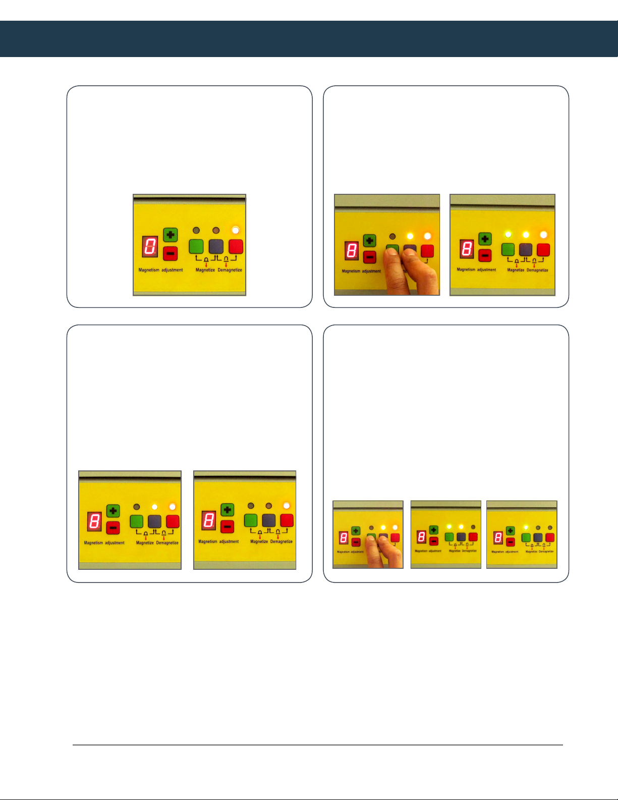
NUMBER DISPLAY FLASHES “0” (DETECT TIME: 5 SEC.)
IF number flashes “0”- the input voltage is
lower than the Controller’s lower limit. Your
voltage is not meeting the controller's minimum
requirement.
YELLOW LIGHT FLASHES FOR 15 SECONDS AND RED
LIGHT REMAINS ON
During the magnetization process, if the red
light remains on and the yellow light flashes
for 15 seconds, this indicates the chuck cable
is disconnected from the chuck.
NUMBER DISPLAY FLASHES “8”
When operating the Controller to magnetize
a chuck, if the red and yellow lights stay lit
and the green light and number “8” flash, this
indicates an SCR failure.
YELLOW LIGHT FLASHES FOR 15 SECONDS AND THEN
GREEN LIGHT REMAINS ON FLASHES
During the magnetization process, if the yellow
light flashes for 15 seconds and then green light
remains on flashes, this indicates one block has
malfunctioned and cannot be magnetized or
demagnetized.
Satisfaction guaranteed on all our CNC tooling solutions | www.techniksusa.com
6
Page 8
TOUCH SCREEN CONTROL OPERATION
1
2
5 7
3
4 6
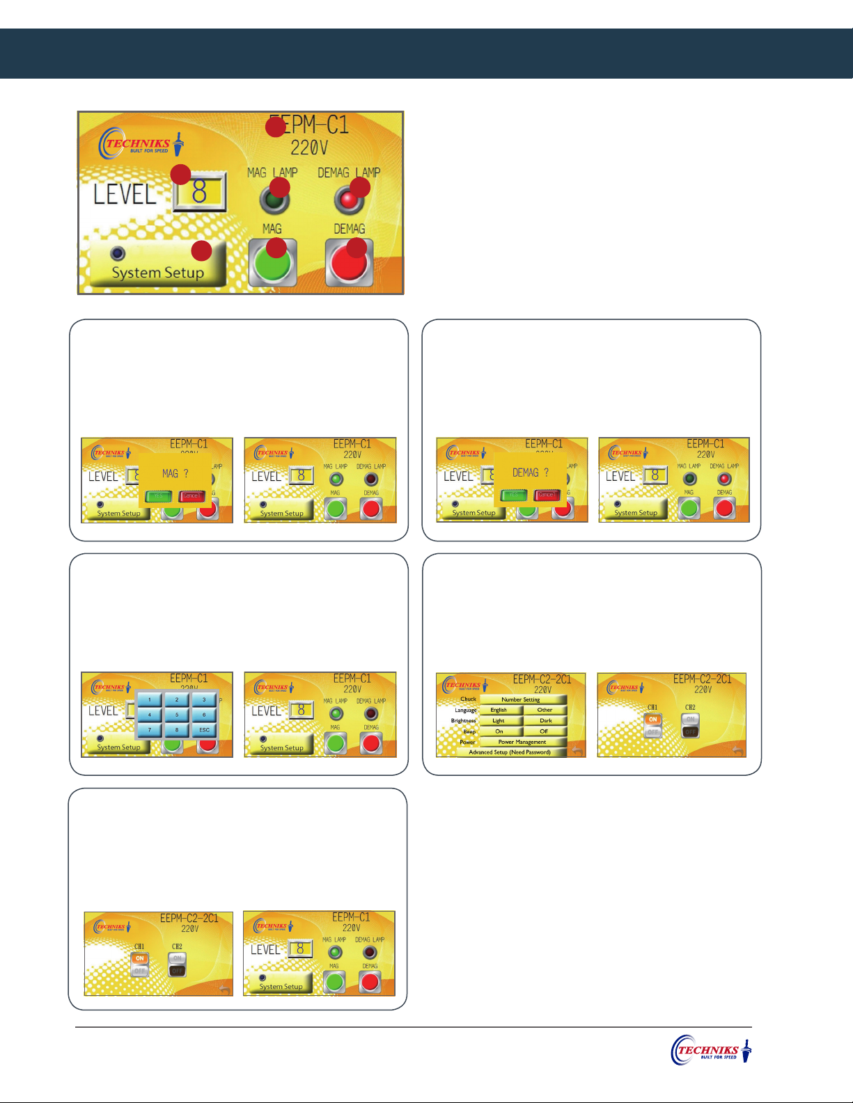
MAGNETIZING THE CHUCK
1. Touch green MAG button.
2. Confirmation prompt will appear, touch YES.
3. Watch for green MAG LAMP light to activate.
1. Specification: Controller Type.
2. Magnetic Force Level: Display current magnetic force level.
3. System Setup : Touch button to enter setting page. Includes
language setup, brightness, buzzer switch, power management,
and advance setting.
4. MAG. Button Push button to conduct chuck magnetization.
5. MAG. Lamp: Green light ON is chuck magnetized.
6. DE-MAG. Button: Push button to conduct chuck demagnetization.
7. DE-MAG. Lamp: Red light ON is chuck demagnetized.
DEMAGNETIZING THE CHUCK
1. Touch red DE-MAG button.
2. Confirmation prompt will appear, touch YES.
3. Watch for red DE-MAG LAMP light to activate.
ADJUSTING HOLDING POWER
1. Touch "LEVEL" setting.
2. Power level pad will appear, touch desired level.
3. Watch for green MAG LAMP light to activate.
ONE CONTROLLER FOR TWO CHUCKS SETTING
1. For EEPM-C2-2C1 can control two EEPM-C1 chucks.
2. Touch "System Setup". Enter Chuck Number Setting.
3. Touch CH1 ON, then go back to Home and Touch MAG.
MULTI-CHUCK CONTROL SETUP
1. Touch System Setup. Enter Chuck Number Setting.
2. Touch On to activate your chucks.
3. Touch Off to de-activate your chucks.
7
Phone: (800) 597-3921 or (317) 803-8000 • Fax: (317) 803-8001
Page 9
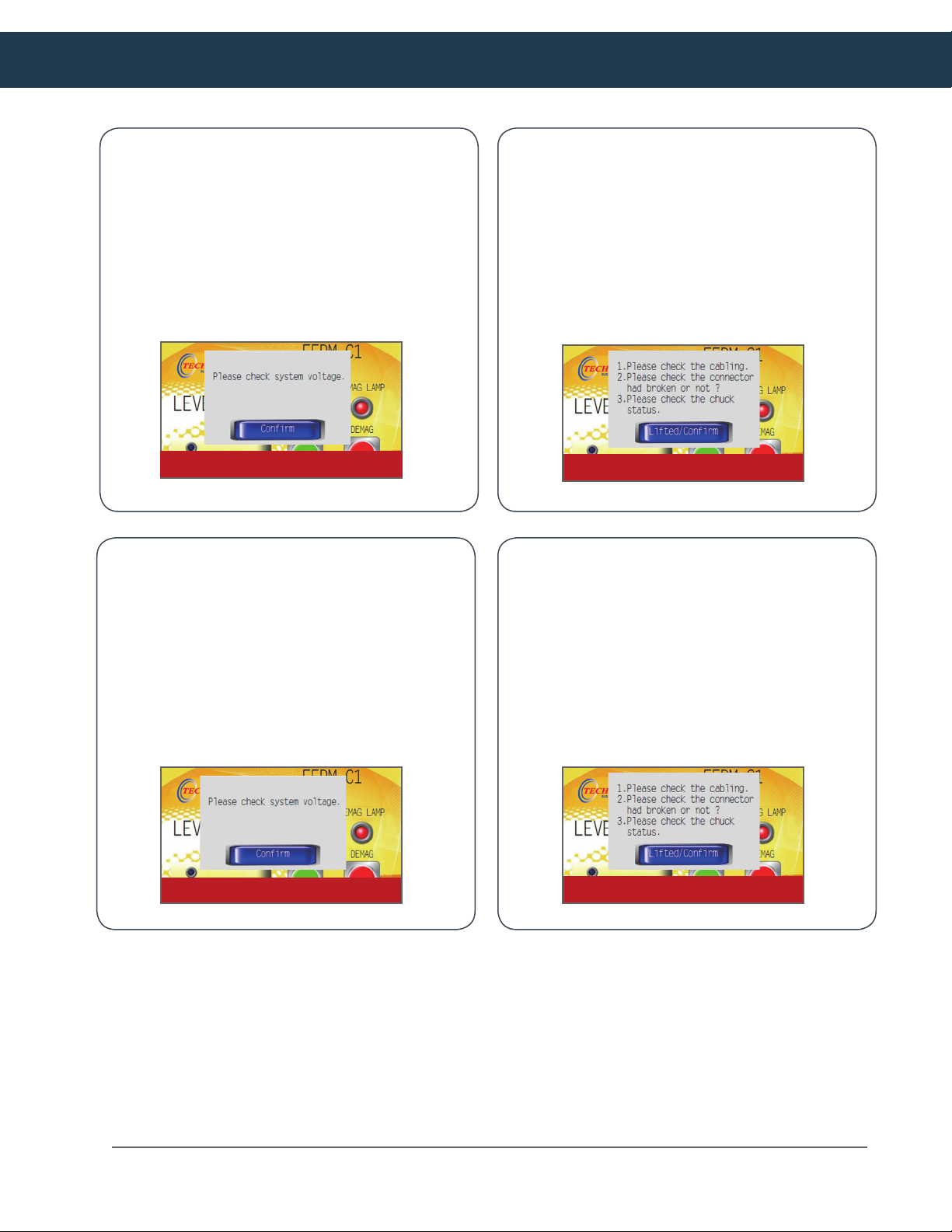
TOUCH SCREEN CONTROL TROUBLESHOOTING
MAGNETIC FAILURE
1. Touch MAG green button.
2. CH1 magnetization failure is displayed.
3. Check if the chuck cable is connected or damaged,
then touch confirm button.
4. Re-start the power, if no warning message is displayed,
the situation is normal.
CH1 MAG ERROR
LOW VOLTAGE
1. A low voltage is displayed if the voltage drops below
186VAC.
2. Check whether the power voltage is within the
acceptable voltage range,Confirm the voltage
improved, then touch disable button.
3. Re-start the power, if no warning is displayed, the
situation is normal.
DEMAGNETIZATION FAILURE
1. Push DE-MAGred button.
2. CH1 demagnetization failure is displayed.
3. Check if the chuck cable is connected or damaged,
then touch confirm button.
4. Re-start the power, if no warning message is displayed,
the situation is normal.
CH1 DEMAG ERROR
CHUCK CABLE DISCONNECTED
1. Touch MA red. button.
2. Chuck cable disconnected message displayed.
3. Check whether the chuck cable is connected, or if the
connector is damaged, then touch confirm button.
4. Touch MAG. button again, if no warning is displayed,
the situation is normal.
LOW POWER (AC220V)
Satisfaction guaranteed on all our CNC tooling solutions | www.techniksusa.com
MISSED LINE
8
Page 10
EEPM CHUCK OPERATIONS
SAFETY PRECAUTIONS
Follow these precautions while servicing the chuck and/or
controller:
• Only qualified personnel should carry out maintenance
operations
• Always make sure the receptacle on the chuck and plug
on the chuck controller cable are free of moisture, chips,
and any contaminants before connecting the chuck
controller cable to the chuck. Failure to do so could result
in damage to the chuck and chuck controller.
• Always replace the cap on the chuck power receptacle
when disconnecting the power cable from the chuck
• Disconnect the equipment from the power supply before
attempting any repairs or maintenance. Never touch
connections or components unless the power supply is
disconnected
• Do not wear rings, watches, necklaces, bracelets etc.
while performing maintenance operations
• Always use protective gloves, safety shoes, and any other
protective gear needed
CHUCK CONTROLLER MAINTENANCE
Regular routine maintenance includes keeping the exterior of
the controller, hand-held remote, and cables clean and dry.
Every time you use the chuck make the following inspections.
1. Carefully inspect all electric connections and condition
of the cables between the chuck and controller, and
the hand-held remote too. Make sure that no part of the
power supply circuit or connections has become loose or
show signs of overheating.
2. Make sure all cycle lamps are functioning well and the
keypad covers are all in good shape.
INDUCTION BLOCK MAINTENANCE
1.
Holding power of the chuck is greatly influenced by
the contact area between the chuck (or induction
blocks) and the workpiece. Regularly check the
condition of all induction blocks and remove any
gouges, rust, or other signs of wear.
2. Machine the top surface of the inductions blocks as
needed to restore them to a smooth, even surface.
PART SETUP
1. Power Up and Demagnetize the EEPM chuck following the
procedures and CautionS and warningS.
2. If you are using fixed or spring-loaded induction blocks
install these on the chuck before loading your workpiece.
Then, machine flat the top surface of the fixed induction
blocks only.
3. Center your workpiece on the chuck. Position it so it covers
an even number of poles (4, 8, etc.) as evenly as possible.
4. Install workstops as needed. Small or thin workpieces
may require workstops to prevent the part from moving
during machining. For best results we recommend using
workstops whenever possible.
5. Adjust the power level as needed using the + or - keys. We
recommend using power level 8 for standard operation.
Magnetize the chuck and verify that it is magnetize.
6. Perform a touch test to verify that the magnetic field is no
longer strong at the surface of the workpiece. If a strong
magnetic field is present on the top of the workpiece adjust
the power level as necessary following the procedures
listed.
7. Verify that the workpiece is properly secured by gently
tapping it on the side with a soft hammer, or striking a
block of wood with a regular hammer while checking for
any movement.
8. After the machining is complete,
EEPM chuck.
You may now remove the workpiece.
Demagnetize the
9
Phone: (800) 597-3921 or (317) 803-8000 • Fax: (317) 803-8001
Page 11

EEPM CHUCK MAINTENANCE
There are no user-serviceable parts inside the chuck. Chuck maintenance is limited the surface finish of
the chuck face and verifying that the electrical connection is clean and uncontaminated by chips or liquid.
Proper maintenance increases the life expectancy of your chuck and controller and keeps them in safe
working condition.
WEEKLY MAINTENANCE
For proper operation the chuck surface must be clean and smooth. Regularly check the surface condition
of all magnetic poles for damage. Remove any gouges or roughness using 250 grit sandpaper with a
backing block. Finish the surface using 400 grit. Remove any rust or scale deposits with 400 grit sandpaper
and a backing block. Remove all dust or other contaminants before storing the chuck or returning it to
operation.
DAILY MAINTENANCE
Unscrew the cap and inspect the electrical socket connection on the front of the chuck. Make sure there
are no chips or other contaminants in the socket. Gently spray the socket and cap with dry shop air. Make
sure the socket and cap are clean and dry, and the cap functions properly and makes a tight seal. Any
contaminants or liquid in the socket may cause damage during magnetize / demagnetize operations.
STORING THE EQUIPMENT
If the need arises to store the equipment for a certain amount of time observe the following instructions.
1. Demagnetize the chuck.
2. Turn the power switch on the chuck controller to “OFF”
3. Disconnect the chuck controller from the power supply
4. Disconnect the controller from the chuck
5. Remove any moisture or debris from the chuck receptacle and replace the cap over the receptacle
6. Clean all components and coat the surface of the chuck in a protective, rust inhibitive solvent.
7. Cover the equipment with a waterproof sheet (plastic)
8. Keep equipment in a dry environment. To preserve all electric parts the room temperature must be between 45°F to 80°F
DISPOSING OF THE EQUIPMENT
If the need arises to dispose of the equipment, it is mandatory to observe a few fundamental rules for the
safeguarding of the environment.
1. Protective covering, flexible pipes, plastic or non-metal material should be dismantled and disposed of separately.
2. The electric components should be disassembled and if in good condition, re-used or recycled, or if that is not possible
properly disposed of according to local municipal regulations.
3. This equipment contains polluting oils that must be disposed of at authorized waste disposal sites.
Satisfaction guaranteed on all our CNC tooling solutions | www.techniksusa.com
10
Page 12

FREQUENT TROUBLESHOOTING SOLUTIONS
Problem:
The controller is ON but the lamp in the remote is not lit.
Solution:
(a) The power supply cable is loose or is not connected properly.
Problem:
The chuck does not magnetize / demagnetize when the correct buttons are pushed.
Solution:
(a) The chuck cable is not properly connected to the controller, or the receptacle contains moisture or debris.
(b) The power supply does not meet the required specifications, or is incorrectly wired to
the controller.
Problem:
Insufficient holding power
Solution:
(a) Verify that the power supply meets the requirements stated in the Power Requirements
section of this manual.
(b) Verify that the power setting on the chuck controller is set to the maximum value(8). The power setting must be
changed when the chuck is in a demagnetized state.
(c) Verify that both the blue and green buttons on the chuck controller or hand-held
remote unit are pressed at the same time for a period of one full second. Do not hold the
buttons down for more than 2 seconds.
(d) Verify that the workpiece covers at least 4 poles and is thick enough, and has enough
iron content to be magnetically attracted to the chuck.
(e) Verify that the mating surfaces of the chuck and the workpiece are clean, smooth, and
free of burrs.
(f) Machine the surface of the fixed pole extensions to ensure a uniform, flat surface.
(g) Remove any oil or coolant from the workpiece and chuck surface before positioning
workpiece on chuck.
(h) Install workstops as needed to prevent slippage.
11
Phone: (800) 597-3921 or (317) 803-8000 • Fax: (317) 803-8001
 Loading...