

Technicstar Ken, Husky User Manual

HUSKY
2 Channel FM Radio Control System
USER'S GUIDE
FM
Proton Control Systems Inc.

Preparation
Husky
Adaptation for Left-hander
Antenna Installation
Loading the Batteries
Charging
Power switch
Direct Servo Control
USB Connection
Standing
Specification
Ken
Installation
Frequency Setting
Specification
Safety
Transmitter and receiver
Operating
Frequency
Battery
Maintenance
Data Setting
Control panel
Normal display
Function map
Direct Access Functions
Digital Trim
Dual Rate
Stopwatch
System Mode Functions
Model Name
Trim Rate
LCD Contrast
Frequency
Data Copy
Pit Mode Functions
Model Select
Setting Level
Servo Reverse
Sub Trim
Data Reset
Circuit Mode Functions
End Point Adjustment
Response
Steering Speed
2-Step Steering Speed
Throttle Speed
2-Step Throttle Speed
Start
3-Step ABS
ABS
Auto Steering Control
Punch
Idle Up
Limited Warranty
Approvals
Frequency list
Table of Contents
Features

Thank you for purchasing a Proton Control Systems product. Before operating your Husky
transmitter and Ken receiver, please read this manual carefully. Then retain it for future
reference.
1. Features
No crystal needed to change frequencies
The frequencies of most transmitters and receivers are adjusted by changing the crystals.
Enthusiasts who want to change frequencies must purchase extra crystal sets to prevent
interference between same frequencies. To complicate matters further there are so many
types of crystals based on modulation (FM/AM, PPM/PCM), conversion type (Single/Dual)
and Radio makers.
To solve this problem, Proton Control Systems adapted PLL (Phase Loop Lock) technology
to your Husky transmitter and Ken receiver. The preferred frequencies are selectable simply by pressing buttons.
Works with all popular FM transmitters & receivers
Your Husky transmitter and Ken receiver are each compatible with all popular FM transmitters and receivers. These include A class (FutabaTM, HitecTM) and B class (JRTM, SanwaTM,
KO
TM
). This flexibility allows you to use different brand transmitters and receivers.
USB port for PC game control
Your Husky is more than a transmitter for your R/C models. Use your Husky transmitter
to control your PC games too! Husky comes with a built-in USB port for connecting to your
personal computer. Now you can practice at home before the big race. Better still, your
race will never be rained out.
Easy to change grip direction for left or right-hander
Husky's symmetrical design allows you to quickly change format from right- to left-hand
grip. Just unscrew 4 screws and rotate the body 180
O
degrees. Who's better than Husky?
Programming features
The program settings on your Husky consist of 3 levels (Expert, Standard, Basic) and 3
modes (System, Pit, Circuit). The programs are simple to set, but offer many powerful functions.
Features
Preparation
2. Preparation
- Husky, 2 Channel FM transmitter
Adaptation for Left-hander
Huskies are produced for right-handers. However the grip direction can be changed
for left-handers.
1. Make sure that the Power switch in set to OFF.
2. Carefully remove the 4 screws from the bottom cover of the control panel.
3. Separate control panel and body
4. Rotate head 180
O
degrees and reinstall the 4 screws being careful not over tight-
en them.

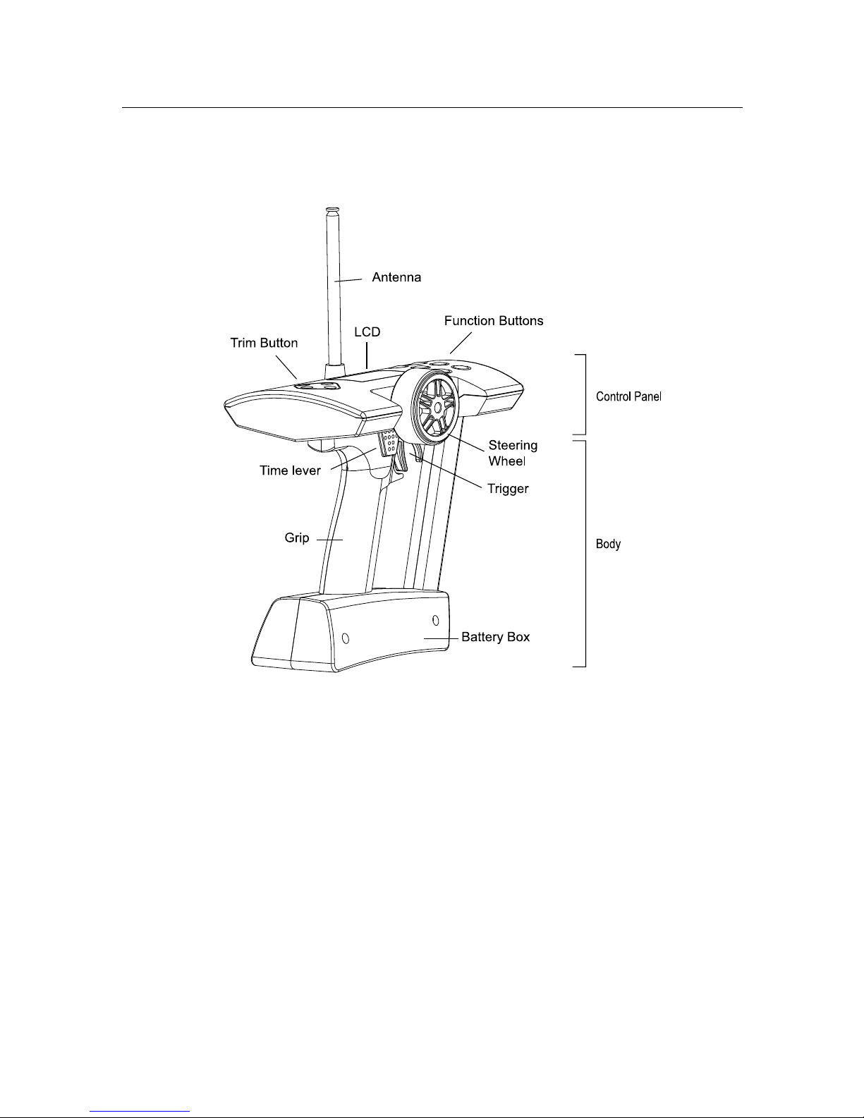
Preparation
Antenna Installation
The antenna included with your Husky is safely stored in a slot under the control
panel. To remove the antenna, pull back the plastic retainer cap located at the
front of your Husky transmitter, then slide the antenna out. Insert the base of the
antenna into the antenna receptacle at the top of the control panel. Then screw the
antenna clockwise until it is firmly attached. Be careful not to over tighten the antenna.
NOTE The antenna should be fully extended while transmitting. Otherwise the operating
range of the system will be reduced and loss of control may occur.
Loading the batteries
Your Husky transmitter requires 8 AA batteries (not included). Alkaline batteries
will provide power for approximately 7 hours of use. The battery box is located at
the bottom of the transmitter body.
1. Make sure that the Power switch is set to the OFF position.
2. Release the hook and pop up automatically the battery cover.
3. Pull down the battery holder and disconnector from the battery case and install
the batteries into the holder.
4. Plug in the connector and replace battery holder into the battery case and push
down the battery cover until it locks in place.
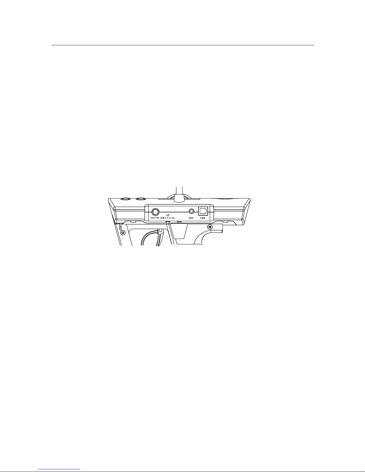
Charging
The changing jack is located on the back side of control panel and marked "12V
". Before start charging, make sure the rechargeable NiCd batteries are installed and power switch is set to the OFF position. For charging the transmitter, the
charger must have below specification. Otherwise it may damage the transmitter or
not be charged.
Input voltage : 110V 60 Hz for USA, 230V 50 Hz for Europe
Output voltage : DC 10.8V 150 mAh
Charge jack polarity :
Typical slow charge rates are DC 10.8V, 150mA for 12 hours, while most Sanyo
brand AAs can be charged at up to 1 Amp.
NOTE Never charge a dry cell type (Non-NiCd) battery. Charging a non NiCd battery may
damage the transmitter, and could cause the battery electrolyte to leak and cause additional
damage.
Preparation
Power switch
The Power switch is a small toggle switch located back of the Control Panel near
the base of the antenna. It can be set to On, Off and Standby (S/B) modes. Power
On and Off is same as any other electronic device. Standby (S/B) allows you to program all functions without transmitting a signal. This is useful for making adjustments while not affecting others that may be on the same frequency. Standby (S/B)
mode also uses about 2/3 less power. If you plan to work in a programming mode
for any length of time or use your Husky as a PC game controller, using Standby
will extend your battery life. "STB" appears on the LCD display in Standby (S/B)
mode.
Battery voltage is displayed both numerically and graphically on the LCD display.
The graphical depiction is a vertical bar on the right side of the display. The length
of the power level bar is gradually reduced according to current consumption.
When voltage drops below 8.7 volts, the bar flashes and an alarm will sound.
NOTE At low voltage, immediately stop the model and change the batteries. Otherwise loss
of model control may result.
Direct Servo Control (using optional cable)
DSC allows you to operate the servos and speed controller in your system without
transmitting (RF) radio frequency. This is ideal for pit checking your radio setup
while others are operating on the same frequency.
To operate, plug the radio connector end of the DSC cable into the DSC jack located behind the control panel of your Husky. The other male end of the DSC cable is
inserted in the battery slot on your Ken receiver.
USB Connection (using optional cable)
Your Husky has a USB port located behind the control panel. It allows connecting
Husky to your computer to control PC games. To transfer control data from your
Husky transmitter, you need to connect the transmitter to your computer. With the
transmitter switch on standby position, plug the "B" type end of the USB cable into
the USB port located on the back of your Husky.
The "A" type end of the USB cable plugs in the USB slot on the backor front of your
computer.
NOTE USB cables are available in a variety of lengths at your local computer store.
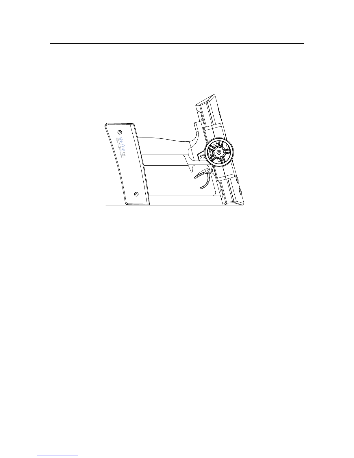
Preparation
Standing
The large control panel at the top of your Husky makes the unit somewhat topheavy. We recommend your Husky stands as illustrated right. This allows better
stability, grip direction and easy of pick-up.
Specifications
Number of Channels : 2
Modulation : FM, PPM
Size : 190 X 185 X 118 mm (7.48" X 7.28" X 4.65")
Weight : 500 g (17.64 oz) w/o batteries
Output power : less than 0.75 W
Current drain : Approx. 250 mA
Power requirements : DC 12V (1.5V X 8, "AA" Size Alkaline batteries)
DC 9.6V (1.2V X 8, "AA" Size NiCd batteries)
Operating temperature : 0
o
C ~ 40o C

LED
1st digit button
2nd digit button
Servo & power slot
Preparation
- Ken, 2 Channel FM Receiver
Installation
For best performance, your Ken receiver should be firmly affixed and connected on
the model according to the procedure below.
1. Clean surface where your Ken is to be mounted.
2. Mount Ken with double-side adhesive tape (included) as close to the antenna
mast as possible.
3. Run the antenna wire up through the plastic antenna tube.
4. Put servo plugs into slots 1 & 2; power plug into slot B.
(Your Ken receiver accepts standard Futaba, JR, Hitec, new Ko and Sanwa Z
connectors).
NOTE Do not cut or bundle the receiver antenna. Cutting, bundling or routing the receiver
antenna near any device that produces noise (RF) will reduce the operating range of the
system and result in loss of control.
Some drivers remove the case to reduce weight, but this can cause serious damage to the
circuitry from dirt or water. Removing the case will void Proton Control System's product
warranty.
Frequency setting
The Ken is a crystal-free receiver. It does not need crystals for changing frequencies. Each available frequency has been assigned a two-digit channel number,
which you can locate at the back of this manual. There is a two-digit LED display
on your Ken receiver with corresponding adjustment buttons. Select the correct
channel number from the back of this manual and then enter that number into
your Ken receiver using the adjustment buttons. When power is first applied to
the receiver, the LED will light for 3 seconds and then turn off. Pressing either adjustment button will light the display again.
NOTE The receiver frequency should be changed on same frequency transmitting. Otherwise it casue servo damage and unexpected accident.
Specification
Number of Channel : 2
Modulation : FM, PPM
Voltage range : 3.5 ~ 10.0 V
Size : 38.1 X 30.5 X 16.5 mm (1.5" X 1.2" X .65")
Weight : 18.70 g (0.66 oz)
Antenna length : 450 mm (17.75")
 Loading...