


HUSKY
2 Channel FM Radio Control System
USER'S GUIDE
FM
Proton Control Systems Inc.

Preparation
Husky
Adaptation for Left-hander
Antenna Installation
Loading the Batteries
Charging
Power switch
Direct Servo Control
USB Connection
Standing
Specification
Ken
Installation
Frequency Setting
Specification
Safety
Transmitter and receiver
Operating
Frequency
Battery
Maintenance
Data Setting
Control panel
Normal display
Function map
Direct Access Functions
Digital Trim
Dual Rate
Stopwatch
System Mode Functions
Model Name
Trim Rate
LCD Contrast
Frequency
Data Copy
Pit Mode Functions
Model Select
Setting Level
Servo Reverse
Sub Trim
Data Reset
Circuit Mode Functions
End Point Adjustment
Response
Steering Speed
2-Step Steering Speed
Throttle Speed
2-Step Throttle Speed
Start
3-Step ABS
ABS
Auto Steering Control
Punch
Idle Up
Limited Warranty
Approvals
Frequency list
Table of Contents
Features

Thank you for purchasing a Proton Control Systems product. Before operating your Husky
transmitter and Ken receiver, please read this manual carefully. Then retain it for future
reference.
1. Features
No crystal needed to change frequencies
The frequencies of most transmitters and receivers are adjusted by changing the crystals.
Enthusiasts who want to change frequencies must purchase extra crystal sets to prevent
interference between same frequencies. To complicate matters further there are so many
types of crystals based on modulation (FM/AM, PPM/PCM), conversion type (Single/Dual)
and Radio makers.
To solve this problem, Proton Control Systems adapted PLL (Phase Loop Lock) technology
to your Husky transmitter and Ken receiver. The preferred frequencies are selectable simply by pressing buttons.
Works with all popular FM transmitters & receivers
Your Husky transmitter and Ken receiver are each compatible with all popular FM transmitters and receivers. These include A class (FutabaTM, HitecTM) and B class (JRTM, SanwaTM,
KO
TM
). This flexibility allows you to use different brand transmitters and receivers.
USB port for PC game control
Your Husky is more than a transmitter for your R/C models. Use your Husky transmitter
to control your PC games too! Husky comes with a built-in USB port for connecting to your
personal computer. Now you can practice at home before the big race. Better still, your
race will never be rained out.
Easy to change grip direction for left or right-hander
Husky's symmetrical design allows you to quickly change format from right- to left-hand
grip. Just unscrew 4 screws and rotate the body 180
O
degrees. Who's better than Husky?
Programming features
The program settings on your Husky consist of 3 levels (Expert, Standard, Basic) and 3
modes (System, Pit, Circuit). The programs are simple to set, but offer many powerful functions.
Features
Preparation
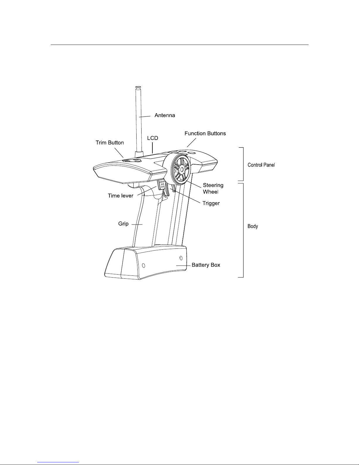
2. Preparation
- Husky, 2 Channel FM transmitter
Adaptation for Left-hander
Huskies are produced for right-handers. However the grip direction can be changed
for left-handers.
1. Make sure that the Power switch in set to OFF.
2. Carefully remove the 4 screws from the bottom cover of the control panel.
3. Separate control panel and body
4. Rotate head 180
O
degrees and reinstall the 4 screws being careful not over tight-
en them.

Preparation
Antenna Installation
The antenna included with your Husky is safely stored in a slot under the control
panel. To remove the antenna, pull back the plastic retainer cap located at the
front of your Husky transmitter, then slide the antenna out. Insert the base of the
antenna into the antenna receptacle at the top of the control panel. Then screw the
antenna clockwise until it is firmly attached. Be careful not to over tighten the antenna.
NOTE The antenna should be fully extended while transmitting. Otherwise the operating
range of the system will be reduced and loss of control may occur.
Loading the batteries
Your Husky transmitter requires 8 AA batteries (not included). Alkaline batteries
will provide power for approximately 7 hours of use. The battery box is located at
the bottom of the transmitter body.
1. Make sure that the Power switch is set to the OFF position.
2. Release the hook and pop up automatically the battery cover.
3. Pull down the battery holder and disconnector from the battery case and install
the batteries into the holder.
4. Plug in the connector and replace battery holder into the battery case and push
down the battery cover until it locks in place.
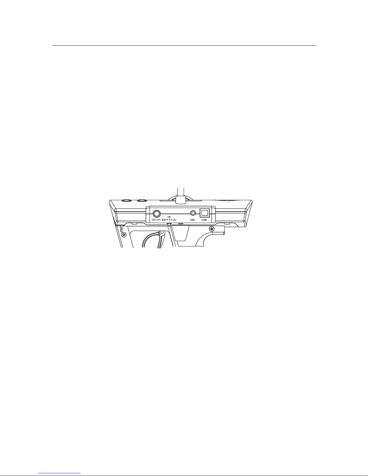
Charging
The changing jack is located on the back side of control panel and marked "12V
". Before start charging, make sure the rechargeable NiCd batteries are installed and power switch is set to the OFF position. For charging the transmitter, the
charger must have below specification. Otherwise it may damage the transmitter or
not be charged.
Input voltage : 110V 60 Hz for USA, 230V 50 Hz for Europe
Output voltage : DC 10.8V 150 mAh
Charge jack polarity :
Typical slow charge rates are DC 10.8V, 150mA for 12 hours, while most Sanyo
brand AAs can be charged at up to 1 Amp.
NOTE Never charge a dry cell type (Non-NiCd) battery. Charging a non NiCd battery may
damage the transmitter, and could cause the battery electrolyte to leak and cause additional
damage.
Preparation
Power switch
The Power switch is a small toggle switch located back of the Control Panel near
the base of the antenna. It can be set to On, Off and Standby (S/B) modes. Power
On and Off is same as any other electronic device. Standby (S/B) allows you to program all functions without transmitting a signal. This is useful for making adjustments while not affecting others that may be on the same frequency. Standby (S/B)
mode also uses about 2/3 less power. If you plan to work in a programming mode
for any length of time or use your Husky as a PC game controller, using Standby
will extend your battery life. "STB" appears on the LCD display in Standby (S/B)
mode.
Battery voltage is displayed both numerically and graphically on the LCD display.
The graphical depiction is a vertical bar on the right side of the display. The length
of the power level bar is gradually reduced according to current consumption.
When voltage drops below 8.7 volts, the bar flashes and an alarm will sound.
NOTE At low voltage, immediately stop the model and change the batteries. Otherwise loss
of model control may result.
Direct Servo Control (using optional cable)
DSC allows you to operate the servos and speed controller in your system without
transmitting (RF) radio frequency. This is ideal for pit checking your radio setup
while others are operating on the same frequency.
To operate, plug the radio connector end of the DSC cable into the DSC jack located behind the control panel of your Husky. The other male end of the DSC cable is
inserted in the battery slot on your Ken receiver.
USB Connection (using optional cable)
Your Husky has a USB port located behind the control panel. It allows connecting
Husky to your computer to control PC games. To transfer control data from your
Husky transmitter, you need to connect the transmitter to your computer. With the
transmitter switch on standby position, plug the "B" type end of the USB cable into
the USB port located on the back of your Husky.
The "A" type end of the USB cable plugs in the USB slot on the backor front of your
computer.
NOTE USB cables are available in a variety of lengths at your local computer store.
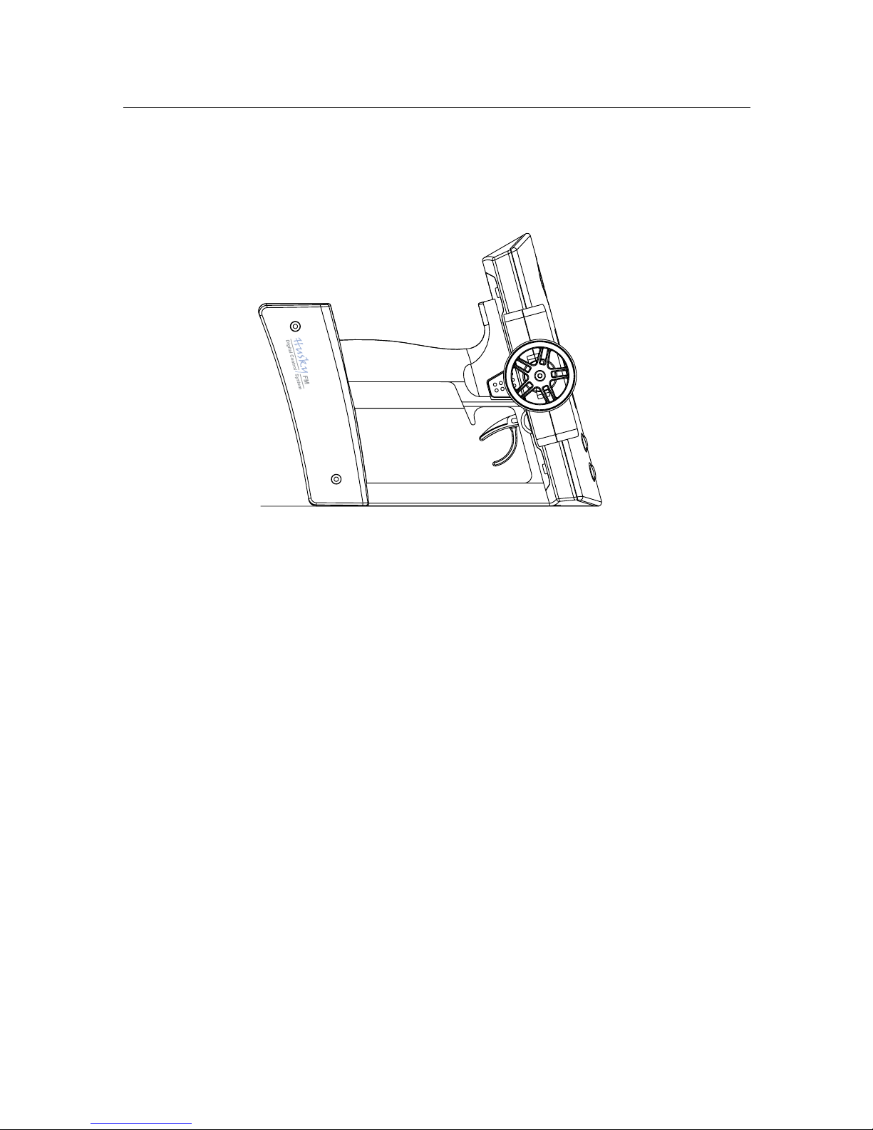
Preparation
Standing
The large control panel at the top of your Husky makes the unit somewhat topheavy. We recommend your Husky stands as illustrated right. This allows better
stability, grip direction and easy of pick-up.
Specifications
Number of Channels : 2
Modulation : FM, PPM
Size : 190 X 185 X 118 mm (7.48" X 7.28" X 4.65")
Weight : 500 g (17.64 oz) w/o batteries
Output power : less than 0.75 W
Current drain : Approx. 250 mA
Power requirements : DC 12V (1.5V X 8, "AA" Size Alkaline batteries)
DC 9.6V (1.2V X 8, "AA" Size NiCd batteries)
Operating temperature : 0
o
C ~ 40o C

LED
1st digit button
2nd digit button
Servo & power slot
Preparation
- Ken, 2 Channel FM Receiver
Installation
For best performance, your Ken receiver should be firmly affixed and connected on
the model according to the procedure below.
1. Clean surface where your Ken is to be mounted.
2. Mount Ken with double-side adhesive tape (included) as close to the antenna
mast as possible.
3. Run the antenna wire up through the plastic antenna tube.
4. Put servo plugs into slots 1 & 2; power plug into slot B.
(Your Ken receiver accepts standard Futaba, JR, Hitec, new Ko and Sanwa Z
connectors).
NOTE Do not cut or bundle the receiver antenna. Cutting, bundling or routing the receiver
antenna near any device that produces noise (RF) will reduce the operating range of the
system and result in loss of control.
Some drivers remove the case to reduce weight, but this can cause serious damage to the
circuitry from dirt or water. Removing the case will void Proton Control System's product
warranty.
Frequency setting
The Ken is a crystal-free receiver. It does not need crystals for changing frequencies. Each available frequency has been assigned a two-digit channel number,
which you can locate at the back of this manual. There is a two-digit LED display
on your Ken receiver with corresponding adjustment buttons. Select the correct
channel number from the back of this manual and then enter that number into
your Ken receiver using the adjustment buttons. When power is first applied to
the receiver, the LED will light for 3 seconds and then turn off. Pressing either adjustment button will light the display again.
NOTE The receiver frequency should be changed on same frequency transmitting. Otherwise it casue servo damage and unexpected accident.
Specification
Number of Channel : 2
Modulation : FM, PPM
Voltage range : 3.5 ~ 10.0 V
Size : 38.1 X 30.5 X 16.5 mm (1.5" X 1.2" X .65")
Weight : 18.70 g (0.66 oz)
Antenna length : 450 mm (17.75")

Safety
2. Safety
Transmitter and receiver
- Do not operate two or more models on the same frequency at the same time. This
will cause interference and loss of control of both models. AM, FM(PPM) and PCM
are different methods of modulation. Nonetheless the same frequency cannot be
used at the same point in time, regardless of the signal format.
- Extend the transmitter antenna to its full length. If the transmitter antenna is not
fully extended the operating range of the radio will be reduced.
- Always perform an operating range check prior to use. Problems with the radio
control system as well as improper installation in a model could cause loss of
control.
- Check the transmitter antenna to be sure it is not loose. If the transmitter anten-
na works itself loose, or is disconnected while the model is running, signal transmission will be lost. This will cause you to lose control of your model.
- Be sure to turn on power switches in the proper sequence. At startup, turn on
transmitter first, then the receiver. At shutdown, turn off the receiver first, then
the transmitter.
NOTE Before powering on, always check the throttle trigger on the transmitter to be sure it
is at the neutral position. When turn off the system power switches always be sure the engine is not running. If the power switches are turned off in reverse order, your model may
unexpectedly and dangerously run out of control.
The signal is transmitting after 5 seconds from turning on the power switch. The 5 seconds
are needed for synthesizing the frequency. So receiver power is turned on at least after 5
seconds from the transmitter power on.
Operating
- Use this product in surface models only. (Car, Boat etc.)
- Do not operate outdoors on rainy days, run through puddles of water or when
visibility is limited. Should any type of moisture (water or snow) enter any component of the system, erratic operation and loss of control may occur.
- Do not operate your R/C system when you are tired, not feeling well or under the
influence of alcohol or drugs. Your judgment is impaired and could result in serious injury to yourself as well as others.
- Do not operate your R/C model in the following places: sites where you may in-
terfere with other radio control activity, where the general public can be found, on
public roads and near high-tension power lines or communication broadcasting
antennas.
- Do not leave your R/C system or model within the reach of small children. A
small child may accidentally operate the system and injuries may result.

Battery
- Ni-Cd batteries can be very dangerous when mishandled and cause chemical
damage.
- In the unlikely event that battery fluid leaks onto your skin, immediately wash
the contaminated skin with soap and plenty of water. Contact your local health
care provider.
- In the unlikely event that battery fluid leaks inside the transmitter. Contact the
PCS service center.
- When the model is not being used, always remove or disconnect the Ni-Cd Bat-
tery. Should the battery be left connected this could created a dangerous situation if someone accidentally turns on the receiver power switch. Loss of control
would occur.
- Always follow your battery manufacturer's directions fully. Do not attempt to dis-
assemble, short circuit, or subject the battery to high temperature or fire.
- Your transmitter has been designed to operate correctly using a variety of AA-size
batteries currently available. These include 1.5 volt alkaline and rechargeable 1.2
volt Nickel Cadmium (Ni-Cd) batteries.
- Replace all batteries of a set at the same time. New batteries should not be mixed
with used ones. Do not mix rechargeable and non-rechargeable batteries. Do not
mix alkaline or Ni-Cd types of batteries. Do not mix different grades or brands of
batteries. Failure to observe this precaution may result in some batteries in a set
being driven beyond their normal exhaust point and increase their possibility of
leakage.
- Always check to be sure your batteries have been charged prior to operating the
model. Should the battery go dead while the model is operating loss of control will
occur and create a very dangerous situation.
- When disposing of batteries, follow the manufacturer's instructions and all feder-
al, state, and local regulations. PCS suggests customers take advantage of any
community battery-recycling programs that may exist in your area. Contact your
local waste remover or recycler for details.
Maintenance
- To keep from damaging your transmitter, avoid exposing it to moisture, extreme
temperatures, direct sunlight, vibration and dust.
- Clean the outside of the transmitter by wiping with a clean, dry cloth. Never use
harsh or abrasive cleaners or organic solvents on the transmitter.
- Do not expose plastic parts to fuel, motor spray, waste oil or exhaust. These will
penetrate and damage the plastic.
- Never disassemble or touch the inside of the transmitter. This could result in
electrical shock.
- If you notice smoke or a burning smell coming from the transmitter, immediately
turn off the transmitter, wait a few minutes until the transmitter cools, and then
remove the batteries.
Safety
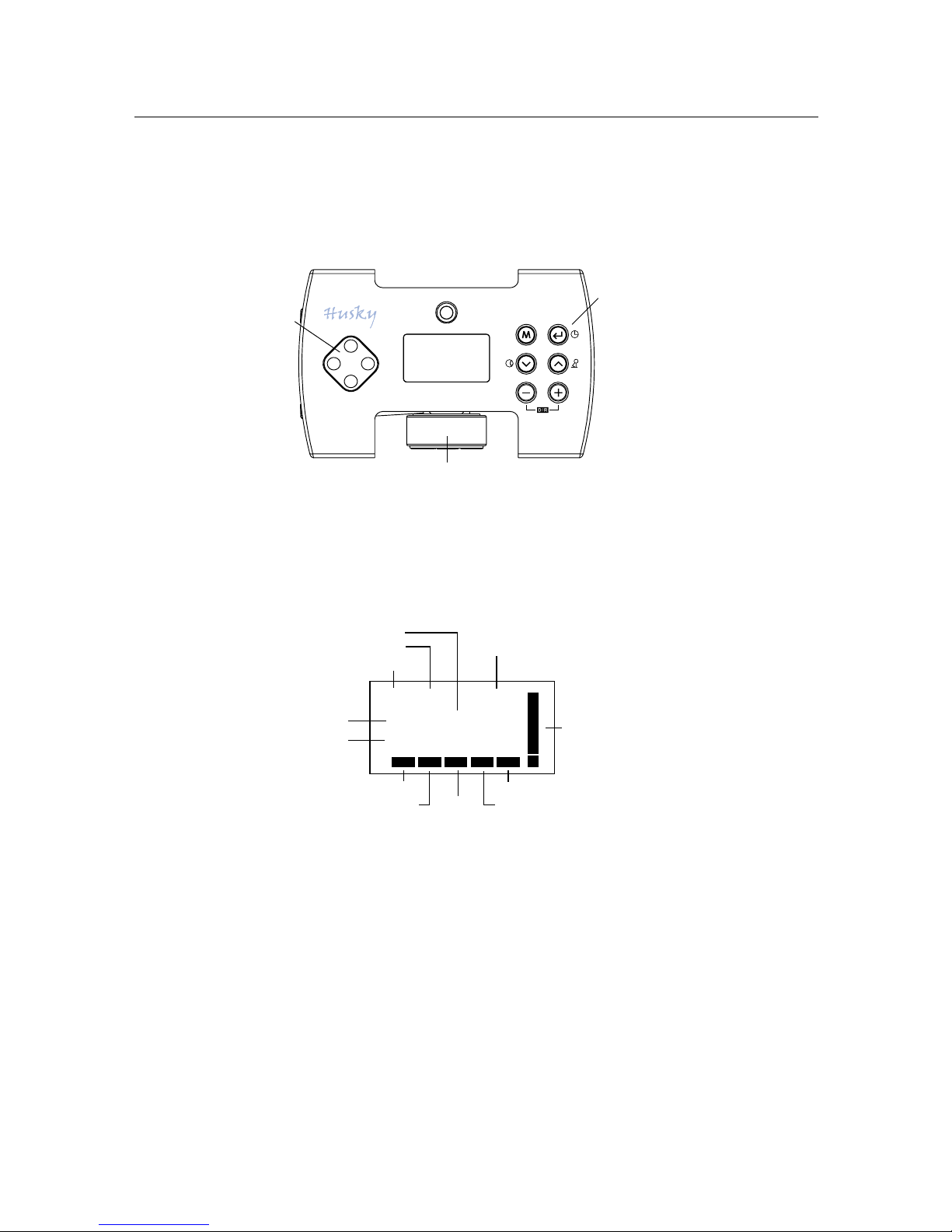
Trim
Button
LCD
Function
Buttons
Steering Wheel
1 : RC10B
12.0 VEx
A40.665 MHz50
D/R STA IDL ABS
ASC
STB
Model #
Model name
Setting level
Voltage
Channel # &
Frequency
Dual rate
Start
Idle up
Anti-lock bracking system
Auto steering control
Power level
bar
Standby
Data Setting
3. Data Setting
There are 3 setting modes (System Mode, Pit Mode and Circuit Mode) in your Husky
setting program.
Control Panel
Normal Display
When the power switch is set to ON or STANDBY the normal display appears as
shown below.

Function
Mode
Circuit Basic
EPA
Response
Dual rate
Standard
EPA
Response
Steering speed
Throttle speed
Start
3-Step ABS
Dual rate
Punch
Idle up
Expert
EPA
Response
2- Step steering speed
2- Step throttle speed
Start
ABS
Auto steering control
Punch
Idle up
Pit
Model select
Setting level
Servo reverse
Sub trim
Data reset
System
Model name
Trim rate
LCD contrast
Frequency
Data copy
Function Map
Data Setting

150%
Dual rate
off
100%
RL
0
Direct Access Functions
Direct set programming lets you program quickly using easily accessible buttons on
the control panel. Make instant fine adjustments without moving through the main
menu.
Digital Trim
The digital trim button is located on the left side of the control panel. Steering and
Throttle trim adjustments can be made by pressing the trim button in one of the 4
available directions. Up and down are for Throttle trim and right and left are for
Steering trim.
You will hear a beep with each increment of trim adjustment. Digital trim position
is displayed both numerically and graphically on the LCD.
NOTE Throttle trim changes only the center (neutral) point and not the end points. This is
done to maintain your maximum speed and braking points.
Dual Rate
Dual rate affects the total steering servo throw (both sides, right and left) simultaneously, so reducing the dual rate value makes the steering less sensitive and also reduces the maximum amount of steering available.
Dual rate values are adjusted and displayed on the LCD by pressing the or
buttons on the control panel.
Pressing dual rate buttons on the control panel, "D/R" will appear on the lower side
of the Normal LCD display.
Stopwatch
Pressing the start button " " on the control panel can activate the stopwatch and display
timer on the LCD. The timer can be started when the throttle is triggered and the stop is available by pressing the start lever behind the steering wheel. Pressing the start button again resets
the stopwatch.
St :
Th:
Trim
R10
F12
Digital Trim / Dual Rate / Stopwatch
00 : 00 : 00
Stopwatch

System Mode Functions
This mode contains programming features, model name, trim rate, LCD contrast,
frequency, data copy and data reset. These basic settings manage the transmitter
system regardless of the pit and circuit mode setting. The System Mode menu is accessible as below.
1. Press button at normal display.
2. Press button 2 times until the cursor is at System Mode.
3. Press button for displaying System Mode menu.
(Display automatically reverts back to Normal mode if there is no activity in System Mode for a period of 5 seconds).
Model Name
For ease of identification, the model name function allows you to assign names up
to 8 characters in length for each of your models
In System Mode, press button to display Model Name screen.
1. Press or button until desired letter appears.
2. Press button and press / button to select next letter.
(To return to the default setting, press , buttons simultaneously for 3 seconds)
3. After model name is completed, press the button to return to the System
menu.
Trim Rate
The trim rate function allows the trim authority (the amount of trim available) to be adjusted. It
allows trim control with fine or rough adjustment.
1. Press button until the cursor is at Trim Rate.
2. Press button to display Trim Rate screen.
3. Press or button to adjust steering trim rate.
4. Press button to select throttle trim rate.
5. Press or button to adjust throttle trim rate.
(To return to the default setting, press , buttons simultaneously for 3 seconds)
6. After setting is completed, press button to return to the System menu.
1 : RC10B2
Model name
Model name
Trim rate
LCD contrast
System Mode
Model Name / Trim Rate
Model name
Trim rate
LCD contrast
System Mode
Steering : 10
Throttle : 10
Trim rate

LCD Contrast
This function allows an eight-step contrast adjustment of the LCD screen.
1. Press button until the cursor is at LCD contrast.
2. Press button to display LCD contrast screen.
3. Press or button until the desired contrast is achieved.
(To return to the default setting, press , buttons simultaneously for 3
seconds)
4. Press button return to the System menu.
Frequency
The frequency feature allows selecting not only frequencies but also classes. There
are 2 classes-A class for Futaba
TM
, KOTM, HitecTM type receivers and B class is for JRTM,
Sanwa
TM
(AirtronicsTM) receivers. BY selecting frequencies and classes, Husky can
control all FM receivers of other manufacturers.
Note Band change is not possible (for example: 27MHz to 75Mhz or 75MHz to 27MHz). To
control a 27MHz FM receiver, you must purchase a 27MHz transmitter. Frequencies can be
changed, but only within a specific band.
1. Press button until the cursor is at Frequency.
2. Press button to display Frequency screen.
3. Press / and button to select the class A or B.
4. Press or button until the cursor is on the desired frequency.
5. Pressing button return to the System menu.
Data Copy
This function copies the entire contents of the currently stored model memory to
another model memory.
1. Press button until the cursor is at Data Copy.
2. Press button to display Data Copy screen.
3. Press / until the desired target model number appears.
4. Press button to copy.
"Complete" is displayed, and then the Data copy menu screen reappears.
Frequency
LCD contrast
Data copy
System Mode
IIIIIIIIIllllllllIIIIIIIIIIII
LCD Contrast
LCD Contrast / Frequency / Data Copy
Frequency
LCD contrast
Data copy
System Mode
Frequency
LCD contrast
Data copy
System Mode
1 : RC10B3
to
2 : Pure 10
Data copy
50 : 40.665 MHz
51 : 40.675 MHz
52 : 40.685 MHz
Frequency A class

Model select
Setting level
Servo direction
Pit Mode
1 : RC10B3
2 : Kyosho
3 : Pure 10
Model select
1
Pit Mode Functions
This mode contains programming for setup during model building, electronics
installation and maintenance. Pit Mode programming features include model select,
setting level, servo direction and sub trim. The Pit Mode menu is accessible as
follows.
1. Press button at normal display.
2. Press button until the cursor is at Pit Mode.
3. Press button to display Pit Mode menu.
(Display automatically reverts back to Normal Mode if there is no activity in Pit
Mode for a period of 5 seconds).
Model Select
The Husky can keep and handle the data for 10 individual models. All programmed
parameters including Digital trim positions are automatically stored in each
memory and up load anytime.
This function is not only useful for someone who has many cars, but great for quick
setting changes based on circuit condition and race type.
1. Press button until the cursor is at Model Select.
2. Press button to display Model Select screen.
3. Press or button until the desired model # appears.
4. Press button return to the Pit menu.
Setting Level
The Husky allows 3 setting levels. The Basic setting allows for easy programming. It
works well for beginners who quickly set-up to go the race circuit. The Standard
and Expert levels offer more advanced programming features.
1. Press button until the cursor is at the Setting Level.
2. Press button to display Setting Level screen.
3. Press or button until the cursor is at desired level.
4. Press button to return to the Pit menu.
Model Select / Setting Level
Model select
Setting level
Servo direction
Pit Mode
Basic
Standard
Expert
Setting level B

Servo Reverse
This function allows you to change the direction a servo rotates, clockwise or counter clockwise.
NOTE When the trim position deviates from the center, the deviation will be on the opposite
side when the servo is reversed.
1. Press button until the cursor is at Servo Reverse.
2. Press button to display Servo Reverse screen.
3. Press / button to change steering servo rotation direction.
4. Press and / button to change throttle servo rotation direction.
(To return to the default setting, press , buttons simultaneously for 3 sec-
onds)
5. Press button to return to the Pit menu.
Sub Trim
Use this function to adjust the neutral position of the steering and throttle.
NOTE Sub trim changes both the center and the end point servo positions. You may want to
recheck your end point positions if you adjust the Sub trim.
Do not use excessive Sub trim, as it's possible to over-run the servo's travel. Instead reposition the servo horn or servo saver on the servo and inspect your linkage installation.
1. Press button until the cursor is at the Sub Trim.
2. Press button to display the Sub Trim screen.
3. Press / button to change the sub trim steering value.
4. Press and / button to change sub trim value of throttle.
(To return to the default setting, press , buttons simultaneously for 3 seconds)
5. Press button return to the Pit menu.
Data Reset
The data reset function resets all the memory (in the current model only) back to
the factory default setting except data in System mode.
1. Press button until the cursor is at Data Reset.
2. Press button to display the Data Reset screen.
3. Press button to move cursor from EXIT to RESET.
4. Press button to reset all data to default values.
"Complete" is then displayed.
NOTE To keep the present data instead of re-setting, press button with the cursor at
Steering Throttle
Servo reverse
Normal
Normal
Model select
Setting level
Servo reverse
Pit Mode
Servo Reverse / Sub Trim / Data Reset
St :
Th:
R4
F2
Sub trim
Sub trim
Servo direction
Pit Mode
Data reset
Sub trim
Servo direction
Pit Mode
Data reset
reset
Data reset
exit

Circuit Mode Functions
Circuit Mode contains the most commonly used programming features that you'll
likely be changing on the circuit. Circuit Mode programming is laid out in 3 levels
that are accessed in user's capability and the kind of race.
The Circuit Mode menu is accessible as shown below.
1. Press button at normal display
2. Press button for displaying Circuit Mode menu.
(Display automatically reverts back to Normal Mode if there is no activity in Circuit Mode for a period of 5 seconds).
End Point Adjustment (EPA)
End Point Adjustment, also referred to as travel adjust or travel volume, allows the
precise maximum servo throw in either direction to be independently adjusted. The
travel adjust range is from 0 - 150% (0 to 60
o
servo travel). This is used to set the
maximum right/left steering and forward/brake position independently. Remember, dual rate and brake trimmers work in unison with travel adjusts.
Note: Be sure that steering and throttle operation does not apply unreasonable
force to the servo horn. Unreasonable force applied to the servo horn may result in
damage to the servo and loss of control.
1. Press button until the cursor is at EPA.
2. Press button to display EPA screen.
3. Press / button until desired EPA value appears on steering left.
4. Press and / button until desired EPA value appears on steering right.
5. Press and / button until desired EPA value appears on throttle forward.
6. Press and / button until desired EPA value appears on throttle back.
(To return to the default setting, press , buttons simultaneously for 3 seconds)
7. Press button to return to the Circuit menu.
EPA
Response
Steering speed
Circuit Mode
Steering
right 100
Throttle
left 100
forw 100
back 100
EPA
EPA

EPA
Response
Steering speed
Circuit Mode
Steering Throttle
10 % forw 10 %
back 10 %
Response
Max
Servo
Angle
Neutral Max
Steering / Throttle Angle
+100%
0%
-100%)
0
Response
This function is used to change the sensitivity of the steering and throttle servos
around the neutral position. It has no effect on the maximum servo travel.
For the throttle servo, the function changes the sensitivity of the throttle servo in
the throttle trigger forward side and brake side directions independently.
1. Press button until the cursor is at Response.
2. Press button to display the Response screen.
3. Press / button until the desired response value appears on steering.
4. Press and / button until desired response value appears on throttle for-
ward.
5. Press and / button until desired response value appears on throttle back.
(To return to the default setting, press , buttons simultaneously for 3 seconds)
6. Press button return to the Circuit menu.
Steering Speed
Steering speed allows you to adjust the steering servo's speed away from center
(turning), and back to center (return) independently.
1. Press button until the cursor is at Steering Speed.
2. Press button to display the Steering Speed screen.
3. Press / button until desired value appears on turning.
4. Press and / button until desired value appears on
returning.
(To return to the default setting, press , buttons simultaneously for 3 seconds)
5. Press button return to the Circuit menu.
Response
EPA
Response
Steering speed
Circuit Mode
turn : 80 retn : 70
Steering speed
Neutral
0
100%
80%
70%
Right / Left
return speed
turn speed

EPA
Response
2-Step St speed
Circuit Mode
turn1 : 80 retn1 : 60
retn2 : 45turn2 : 75
c.p 45 c.p 50
2-Step steering speed
100%
Neutral
Right / Left
turn speed
return speed
80%
75%
0
60%
45%
45 50
change point
2-Step Steering Speed
This function is similar to Steering Speed, but it has speed change points. You adjust the steering servo's speed independently away from center (turning), and back
to center (return), as above. You can also select points in both turn and return,
and the speed between each point can be independently selected.
1. Press button until the cursor is at 2-Step Steering Speed.
2. Press button to display the 2-Step Steering Speed screen.
3. Press / button until the desired value appears on turning 1.
4. Press and / button until the desired value appears on turning change
point.
5. Press and / button until the desired value appears on turning 2.
6. Press and / button until the desired value appears on returning 1.
7. Press and / button until the desired value appears on returning change
point.
8. Press and / button until the desired value appears on returning 2.
(To return to default setting, press , buttons simultaneously for 3 seconds)
9. Press button to return to the Circuit menu.
Throttle Speed
This function allows you to adjust the throttle servo's speed independently away
from neutral (at acceleration), and back to neutral (at deceleration).
1. Press button until the cursor is at Throttle Speed.
2. Press button to display the Throttle Speed screen.
3. Press / button until desired value appears on throttle speed forward.
4. Press and / button until desired value appears on throttle speed back.
(To return to the default setting, press , buttons simultaneously for 3 seconds)
5. Press the button to the return to the Circuit menu.
2-Step Steering Speed / Throttle Speed
change point
acceleration speed
decelelration speed
Trigger
Speed
Max
100%
Neutral
90%
75%
0
50
accel : 90 decel : 75
Throttle speed
Response
Steering speed
Throttle speed
Circuit Mode

acceleration speed
decelelration speed
Trigger
Speed
Max
change point
100%
Neutral
80%
75%
0
50
Response
Steering speed
2-Step St speed
Circuit Mode
turn1 : 80 retn1 : 60
retn2 : 45turn2 : 75
c.p 45 c.p 50
2-Step steering speed
60%
45%
45
2-Step Throttle Speed
This function is similar with Throttle speed but it has speed change points. You adjust the throttle servo's speed independently away from neutral (at acceleration),
and back to neutral (at deceleration), as above. You can also select points in both
acceleration and deceleration, and the speed between each point can be independently selected.
1. Press button until the cursor is at 2-Step Throttle Speed.
2. Press button to display 2-Step the Throttle Speed screen.
3. Press / button until the desired value appears on acceleration low.
4. Press and / button until the desired value appears on acceleration
change point.
5. Press and / button until the desired value appears on acceleration high.
6. Press and / button until the desired value appears on deceleration low.
7. Press and / button until the desired value appears on deceleration
change point.
8. Press and / button until desired value appears on deceleration high.
(To return to the default setting, press , buttons simultaneously for 3 seconds)
9. Press button return to the Circuit menu.
Start
This feature allows for smooth and even acceleration under adverse conditions,
such as a wet circuit. When the start function is activated, merely operating the
throttle trigger slowly causes the throttle servo to automatically switch from the set
trigger position to a preset point so that the tires do no loose their grip and the car
accelerates smoothly. By pressing the start button " " on control panel, "STA" will
appear on the lower side of the Normal LCD display. The Start function is only
available at the first triggering. For activating again, press the start button on the
control panel.
1. Press button until the cursor is at Start.
2. Press button to display the Start screen.
3. Press / button until desired value appears on throttle position.
4. Press and / button until desired value appears on trigger position.
(To return to the default setting, press , buttons simultaneously for 3 sec-
onds)
5. Press button return to the Circuit menu.
2-Step Throttle Speed / Start
Throttle speed
Start
A.B.S
Circuit Mode
throttle : 0
trigger : 5
Start off
Positon

3-Step A.B.S / A.B.S
3-Step A.B.S
This function allows you to select 1 of 3 A.B.S settings based on circuit and race
conditions.
1. Press button until the cursor is at 3-Step ABS.
2. Press button to display the 3-Step ABS screen.
3. Press / button until the cursor is at the desired level.
(To return to the default setting, press , buttons simultaneously for 3
seconds)
4. Press button return to the Circuit menu.
Anti-lock Breaking System (A.B.S)
Your Husky features an advanced anti-lock breaking system! A.B.S works as a
pulse brake, allowing greater stability and control during hard braking. The pulse
width ("on" time versus "off" time) is called duty, the pulse height (how hard the
brakes pulse) is called width, and the braking point where ABS actually begins is
called position. A delay can be programmed so that regular braking occurs first,
then at a pre-set delay ABS braking begins.
1. Press button until the cursor is at ABS.
2. Press button to display the ABS screen.
3. Press / button until desired value appears on width.
4. Press and / button until desired value appears on position.
5. Press and / button until desired value appears on cycle.
6. Press and / button until desired value appears on delay.
7. Press and / button until desired value appears on duty.
(To return to the default setting, press , buttons simultaneously for 3 seconds)
8. Press button return to the Circuit menu.
Throttle speed
Start
A.B.S
Circuit Mode
Fast
Off
Slow
Medium
A.B.S off
Throttle speed
Start
A.B.S
Circuit Mode
width : 0
position : B5
cycle : 1
A.B.S off
width
A
B
Position
cycle
A : B = Duty
Start Max

Auto St control
Punch
Idle
Circuit Mode
Low High
Steering
Speed
change point
100%
80%
70%
0
50
speed L : 80
speed H : 70
Th c.p 50
Auto steering control
Auto Steering Control
This function allows two steering servo speeds, automatically adjusted at high- and
low-speed range of throttle. When it is activated, "ASC" appears on the lower side of
the Normal LCD display.
If you want sensitive steering at corners and less sensitive steering on the straightaway, reduce the auto steering speed value at high-speed range and increase the
value at low-speed range. The reverse is also available.
NOTE 2-Step steering speed is deactivated on Auto steering control.
1. Press button until the cursor is at Auto Steering Control.
2. Press button to display the Auto Steering Control screen.
3. Press / button until the desired value appears on speed low.
4. Press and / button until the desired value appears on change point.
5. Press and / button until the desired value appears on speed high.
(To return to the default setting, press , buttons simultaneously for 3 seconds)
6. Press button to return to the Circuit menu.
Auto Steering Control

Auto St speed
Punch
Idle
Circuit Mode
Steering
Throttle
20%
30%
40%
forw
back
Punch
Punch
The Punch throttle feature is used to reduce or eliminate the dead throttle area
that exists from neutral to the starting point of throttle and from neutral to the
starting point of braking.
This area is sometimes known as dead band. As more throttle trim (also known as
static brake) is applied, more of the dead trigger area right off neutral exists. Adjust
a forward value such that your vehicle's wheels just start to turn when the trigger
is slightly squeezed. This gives the most accurate feel and eliminates this dead
area.
This feature is also available for steering. Steering Punch can eliminate dead band
around neutral.
1. Press button until the cursor is at Punch.
2. Press button to display the Punch screen.
3. Press / button until the desired value appears on steering position.
4. Press and / button until the desired value appears on throttle forward
position.
5. Press and / button until the desired value appears on throttle back position.
(To return to the default setting, press , buttons simultaneously for 3 seconds)
6. Press button return to the Circuit menu.
Idle Up
The Idle up function is normally used to advance the throttle position slightly,
making it easier to start gas cars. Pressing the Idle up button " " on the control
panel can activate this function, the throttle servo will offset to the pre-programmed position, and "IDL" will appear on the lower side of the Normal LCD display.
NOTE Idle up is available only at first triggering. For activating, press Idle up button on the
control panel again.
1. Press button until the cursor is at Idle Up.
2. Press button to display the Idle Up screen.
3. Press / button until the desired value appears on throttle position.
(To return to the default setting, press , buttons simultaneously for 3 seconds)
4. Press button return to the Circuit menu.
Max
Servo
Angle
Neutral Max
Steering/Throttle Angle
100%
0
Punch
Auto St speed
Punch
Idle
Circuit Mode
Throttle
Idel up
off
position : 0

4. Limited Warranty
Proton Control Systems, Inc. guarantees your Husky and Ken to be free from defects in materials and workmanship for a period of 120 days from original date of
purchase (verified by dated, itemized sales receipt). Warranty does not cover incorrect installation, components worn by use or excessive force, altering the antenna,
exceeding the recommended input voltage, using the Ken without its case, tampering with the electronics, allowing water, moisture, or any foreign material to enter
your Husky and Ken or come in contact with the PC board, incorrect installation,
or any damage caused by vibration, shock, or a crash. In no case shall our liability
exceed product's original cost. We reserve the right to modify warranty provisions
without notice. Because Proton Control Systems, Inc. has no control over connection and use of receiver, no liability may be assumed nor will be accepted for damage resulting from the use of this product. Every Husky and Ken are thoroughly
tested and tuned before leaving our facility, and is therefore considered operational.
By the act of connecting/operating Husky and Ken, the user accepts all resulting
liability.
5. Approval
CE
The R&TTE (Radio Equipment & Telecommunications Terminal Equipment) directive is the new European directive relating to radio equipment and telecommunications transmission equipment. It also covers the collective recognition of the conformity of such equipment. One part of the R&TTE directive regulates the
introduction and operation of radio systems in the European Community.
An important change is the abolition of approval. The manufacturer or importer
must subject radio equipment to a conformity appraisal process before that equipment is introduced.
The CE symbol is attached to the device to indicate that it conforms with the valid
European norms.
An exclamation mark is also to be attached to radio transmitting equipment, to indicate that the permissible frequencies are not yet uniform throughout Europe.
This requirement applies to all the countries included in the list attached.
It is essential to note that these radio control systems may only be operated on the
approved frequencies, as listed in the table.
Please note that the user bears the responsibility for compliance with this requirement, and for ensureing that the radio system complies with the directives.
In Germany the requirement to purchase a licence for the operation of 35 MHz systems remains in effect; please refer to the operating instructions, or the separate
sheet included with them.
Limited Warranty / Approval
Proton Control Systems Inc.
182-4 Dodang-dong Wonmi-ku Bucheon-city

6. Frequency List
- 40MHz, Europe
50 40.665
51 40.675
52 40.685
53 40.695
54 40.715
55 40.725
56 40.735
57 40.765
58 40.775
59 40.785
81 40.815
82 40.825
83 40.835
84 40.865
85 40.875
86 40.885
87 40.915
88 40.925
89 40.935
90 40.965
91 40.975
92 40.985
D 50 ~ 92 40.665 ~ 40.985
B 50 ~ 53 40.665 ~ 40.695
DK 50 ~ 53 40.665 ~ 40.695
GB 50 ~ 92 40.665 ~ 40.985
SF 50 ~ 57, 59 40.665 ~ 40.765, 40.785
GR 50 ~ 92 40.665 ~ 40.985
IRL 51 ~ 91 40.665 ~ 40.975
IS 50 ~ 91 40.665 ~ 40.975
I 50 ~ 84 40.665 ~ 40.865
L 50 ~ 54 40.665 ~ 40.695
NL 50 ~ 53 40.665 ~ 40.715
N 50 ~ 59 40.665 ~ 40.785
A 50 ~ 53 40.665 ~ 40.695
P 50 ~ 54 40.665 ~ 40.695
S 50 ~ 56 40.665 ~ 40.735
E 50 ~ 53 40.665 ~ 40.695
CH 50 ~ 92 40.665 ~ 40.985
Frequency List
Proton Control Systems Inc.
182-4 Dodang-dong Wonmi-ku Bucheon-city
 Loading...