

Page 1
ORDER NO. EMID0004007C0
09/08/2012
www.nostatech.nl
World of free manuals
A5
Digital Piano
SX-PX554 / SX-PX554M
(P) U.S.A.
(PC) Canada
(PY) Mexico
(EX) Norway, Sweden, Denmark, Finland, Spain, Portugal, Greece, South
Africa
(EZ) Germany
(EG) Switzerland, Italy, Austria, Holland, Belgium, France
(EB) the United Kingdom
(GN) Australia, New Zealand
(XS) Malaysia, Singapore
(XT) Taiwan
(X) Thailand, Columbia, Panama, Philippines
(XA) Argentina
(XD) Hong, Kong
SPECIFICATIONS
SPECIFICATIONS
1
Page 2

Digital Piano 1
09/08/2012
www.nostatech.nl
World of free manuals
SPECIFICATIONS 1
1. WARNING 3
2. SAFETY PRECAUTION 3
2.1. Safety precaution 3
2.2. Insulation resistance test 4
3. OWNERS MANUAL 4
4. HOW TO ASSEMBLE THE PIANO 4
5. KEYBOARD RANGES 6
6. PARTS LOCATION 7
7. DISASSEMBLY INSTRUCTIONS 7
7.1. Removing the top cover 7
7.2. Removing the keyboard cover 7
7.3. Removing the control panel 8
7.4. Removing the keyboard assembly 8
7.5. Key(s) 9
7.6. Disassembly of the pedal assembly 10
7.7. Removing the speakers 10
7.8. Removing the printed circuit boards 11
8. SELF-DIAGNOSTIC FUNCTIONS 12
9. PRECAUTIONS BEFORE SERVICING 14
9.1. Precautions for measuring of the output waveforms 14
9.2. Important safety notice 15
9.3. Symbolic marks 15
9.3.1. Resistors 15
Table-1 15
9.3.2. Capacitors 16
Table-2 16
10. MEASURING CONDITION 16
10.1. Measuring condition of MAIN P.C.B. 17
10.2. Measuring condition of FAJSP P.C.B. 17
11. SCHEMATIC DIAGRAM 18
12. PRINTED CIRCUIT BOARD 18
12.1. MAIN, FAJSP, CPL P.C.B. 18
12.2. CPR, MKB1, MKB2, PKB, COM, HP P.C.B. 18
13. BLOCK DIAGRAM 18
14. WIRING CONNECTION DIAGRAM 18
15. REPLACEMENT PARTS LIST 18
16. CABINET PARTS LOCATION 37
17. PACKAGING 40
svcdoc
I
Page 3

KEYBOARD
09/08/2012
www.nostatech.nl
World of free manuals
MAX. POLYPHONY
SOUND
PEDAL
BRILLIANCE
DIGITAL EFFECT
DIGITAL REVERB
TOUCH SENSITIVITY
TRANSPOSE
TUNING
METRONOME
SEQUENCER
DISPLAY
DEMO
MIDI
MODE SET
OTHERS
OUTPUT
SPEAKERS
POWER REQUIREMENT
DIMENSIONS (W×H×D)
NET WEIGHT
ACCESSORIES
88 KEYS
64 NOTES
18 SOUNDS: CONCERT
GRAND, POP GRAND,
UPRIGHT, E PIANO 1, E PIANO
2, HARPSI, VIBES, STRINGS,
VOCAL, ORGAN PRESETS
SOFT, SOSTENUTO, SUSTAIN
MELLOW, BRIGHT (5 STEPS)
Supported
Supported (ROOM, STAGE,
HALL, CONCERT)
LIGHT, NORMAL, HEAVY
G - C - F#
427.3Hz-440.0Hz-453.0Hz
Supported (TIME SIGNATURE:
OFF, 2/4, 3/4, 4/4, 5/4, 6/8)
TRACK (1, 2), STORAGE
CAPACITY: APPROX. 4500
NOTES, RECORDING MODE:
REAL TIME
Supported
Supported
MILTI TIMBRE, LOCAL
CONTROL, OMNI ON,
PROGRAM CHANGE, PEDAL,
EFFECT, TRANSPOSE
PIANO TUNING, MINIMUM
RANGE
POWER SWITCH, MAIN VOLME,
MIDI TERMINALS (IN, OUT),
PEDAL IN, AUX IN (R/R+L,L),
LINE OUT (R/R+L,L),
COMPUTER, HEADPHONES ×
2, AC IN, INITIAL KEY
120 W (60 W × 2)
14 cm × 2, 6.5 cm × 2
160 W
AC 120V/220/230-240 V 50/60Hz
/ AC 120V 60Hz (NORTH
AMERICA AND MEXICO) /
AC230-240 V 50/60Hz
(EUROPE, AUSTRALIA AND
NEWZEALAND)
138.7 cm × 106.4 cm × 52 cm (54
-19/32” x 41-7/8” x 20-15/32”)
56 kg (123.5 lbs.)
AC CORD
2000 Matsushita Electric Industrial Co., Ltd. All rights reserved.
Unauthorized copying and distribution is a violation of law.
2
Page 4

1. WARNING
09/08/2012
www.nostatech.nl
World of free manuals
To prevent the risk of fire, smoke, or electrical shock and to ensure safe operation, please be sure to
follow the safety guidelines below.
1. At places where special caution is required, the necessary safety
precautions are clearly labeled or printed, for example, on the cabinet,
or on the part concerned. Please follow these safety precautions, and
also those listed in the Owner's Manual.
2. Parts which have a
mark in the circuit diagram or in the parts list
are essential for safety. When replacing these parts, be sure to use
only the specified parts.
3. Use the specified types for internal wiring (double-insulated wiring,
etc.).
4. When replacing parts on the AC primary side (power transformer,
electric switch, electrical cord, noise-prevention condenser, etc.), wind
the lead wire and secure it by soldering.
5. Do not let the wiring come into contact with heat-emitting devices
(fuse resistor, radiator plate, etc.).
6. When replacing the wiring, make sure that it is not in contact with the
unfinished or rough edge of a part.
7. When replacing the power cord (except for the plug-in type), tug it
from various directions to confirm that it does not slip out of place.
8. Spacing
If soldering was done on the AC primary circuit, confirm that the
interval between the soldered terminals or between the terminal and
surrounding metallic parts is at least the minimum required (between
the primary circuit and the chassis: at least 6.5 mm; between primary
circuit terminals: at least 4.0 mm; between primary circuit terminals
and secondary circuit terminals: at least 6.5 mm.).
2. SAFETY PRECAUTION
2.1. Safety precaution
1. Before servicing, unplug the power cord to prevent an electric shock.
2. When replacing parts, use only the manufacturer’s recommended
3
Page 5
components for safety.
09/08/2012
www.nostatech.nl
World of free manuals
3. Check the condition of the power cord. Replace if wear or damage is
evident.
4. After servicing, be sure to restore the lead dress, insulation barriers,
insulation papers, shields, etc.
5. Before returning the serviced equipment to the customer, be sure to
make the following insulation resistance test to prevent the customer
from being exposed to a shock hazard.
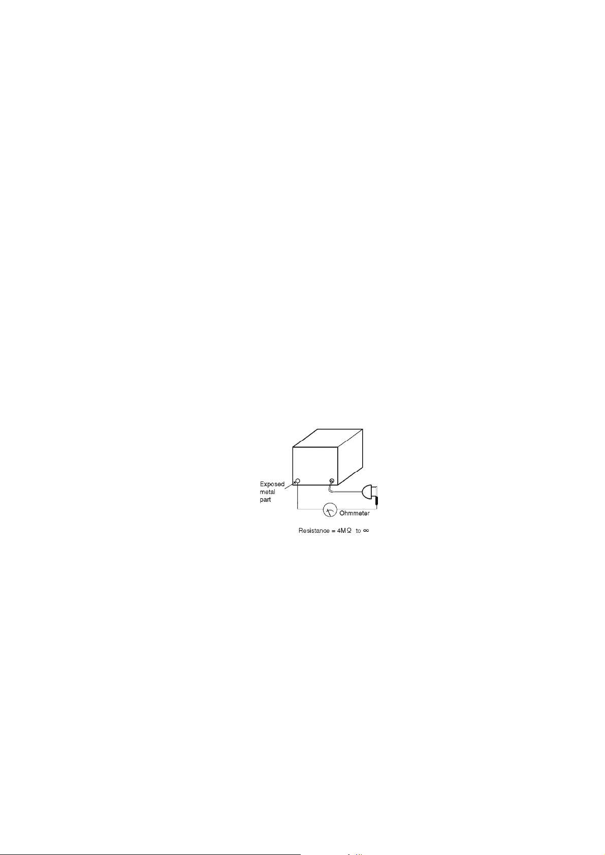
2.2. Insulation resistance test
1. Unplug the power cord and short the prongs of the plug with a jumper
wire.
2. Turn on the power switch.
3. Measure the resistance value with an ohmmeter between the jumpered
AC plug and each exposed metal cabinet part, such as screw heads,
connectors, control shafts, handle brackets, etc. Measurements
should range from 4 M Ohm to infinity for all exposed parts.
Figure-1
3. OWNERS MANUAL
4. HOW TO ASSEMBLE THE PIANO
To prevent the piano unit from falling off the stand, secure it firmly with the screws.
1. Assemble the right and left planks
- Assemble the right and left planks to the pedal box with the 4 brass-
colored screws.
- Loosen the pedal cord, stowed on the inner side of the pedal box, and
extend it.
Figure-2
4
Page 6
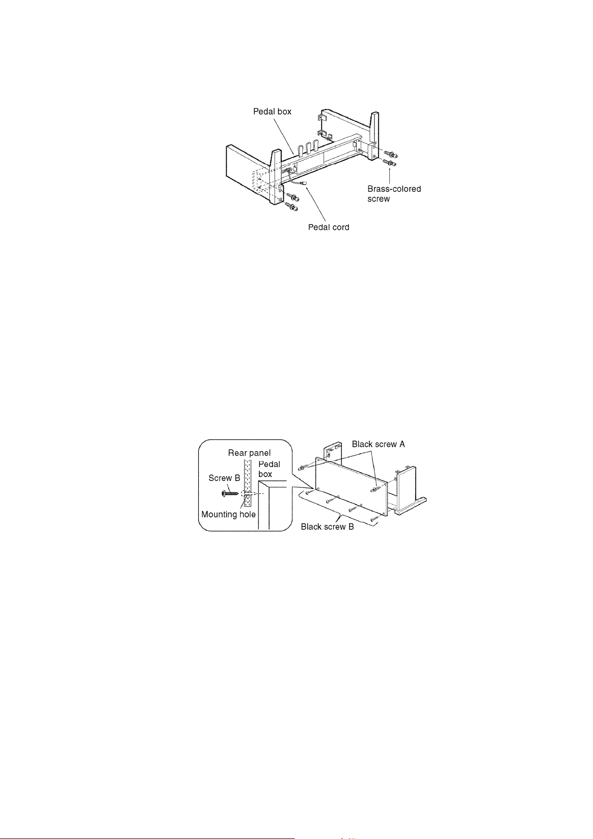
2. Place the stand uplight and mount the panel
09/08/2012
www.nostatech.nl
World of free manuals
- Place the stand upright and mount the rear panel with 2 black screws A
and 4 black screws B.
- Run the screws directly into the pedal box as there are no rough holes
in the pedal box.
Figure-3
3. Place the piano body
- Place the piano body on the stand and secure it with 4 black screws A.
Figure-4
5
Page 7
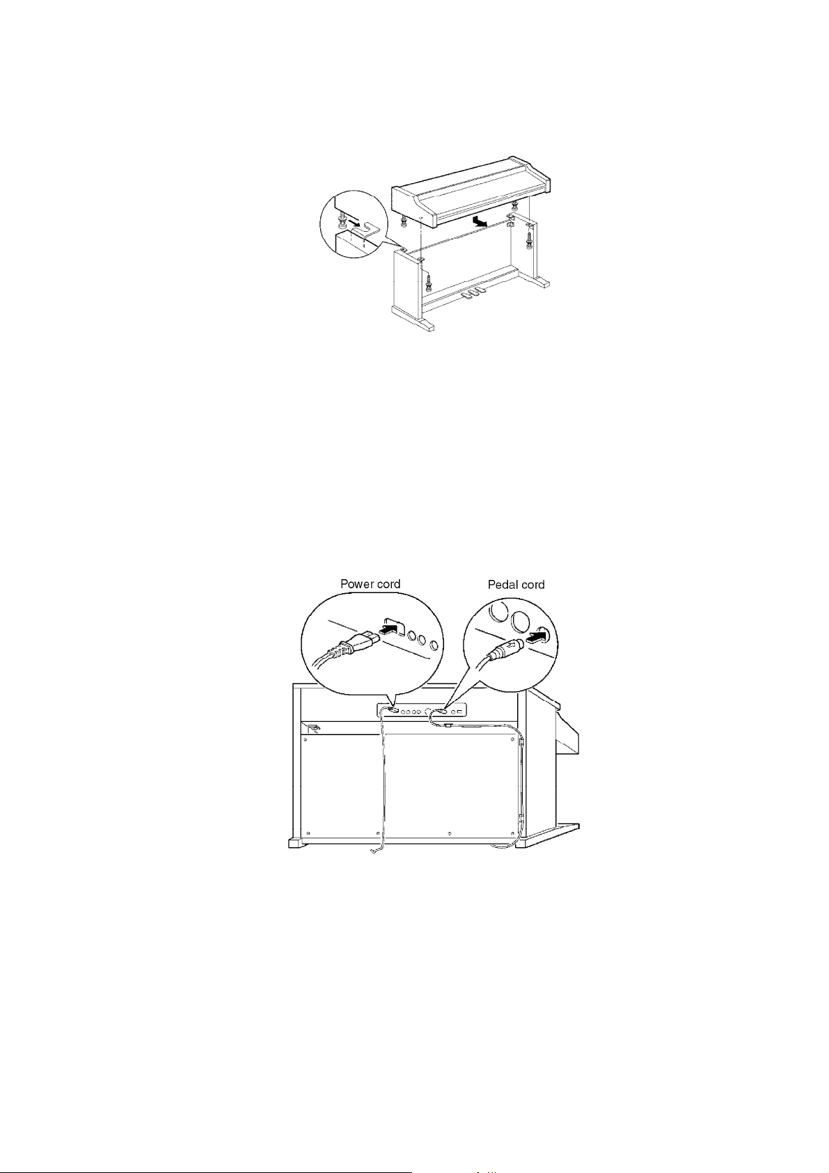
4. Connect the pedal cord and power cord
09/08/2012
www.nostatech.nl
World of free manuals
- Connect the pedal cord and power cord to the terminals located on the
rear of the piano unit as shown below.
- Secure the pedal cord to the clamps as shown in the figure.
Figure-5
5. KEYBOARD RANGES
This keyboard features Touch Response, by which you control the volume by playing the keys harder
or softer.
Figure-6
6
Page 8
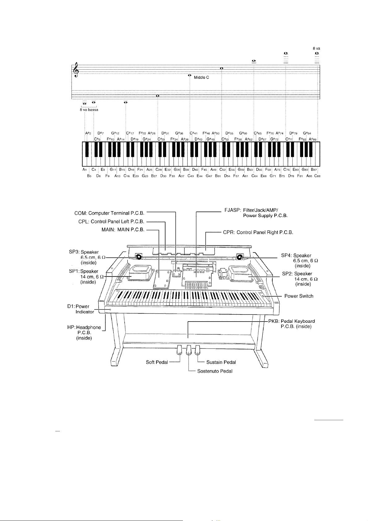
6. PARTS LOCATION
09/08/2012
www.nostatech.nl
World of free manuals
Figure-7
7. DISASSEMBLY INSTRUCTIONS
7.1. Removing the top cover
1. Remove the top cover mounting screws (A 4 pcs.) as shown in
8.
2. Slide the top cover forward and lift up (as shown by the arrows).
7.2. Removing the keyboard cover
Figure-
7
Page 9
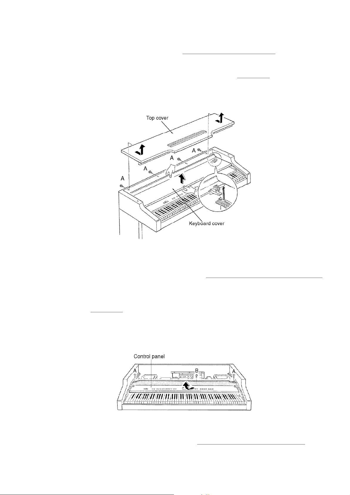
1. Remove the top cover (see step “Removing the top cover”).
09/08/2012
www.nostatech.nl
World of free manuals
2. Match the gears of the keyboard cover with the notches in the guide
rail, and lift up the keyboard cover as shown in
Figure-8
Figure-8.
7.3. Removing the control panel
- Pull out the connectors on the control panel.
1. Remove the keyboard cover (see step “
Removing the keyboard cover
”).
2. Remove the control panel mounting screws (A 2 pcs. and B 1 pc.) as
shown in
Figure-9.
3. Slide the control panel forward and pull out (as shown by the arrow).
Figure-9
7.4. Removing the keyboard assembly
1. Remove the control panel (see step “
Removing the control panel).
8
Page 10
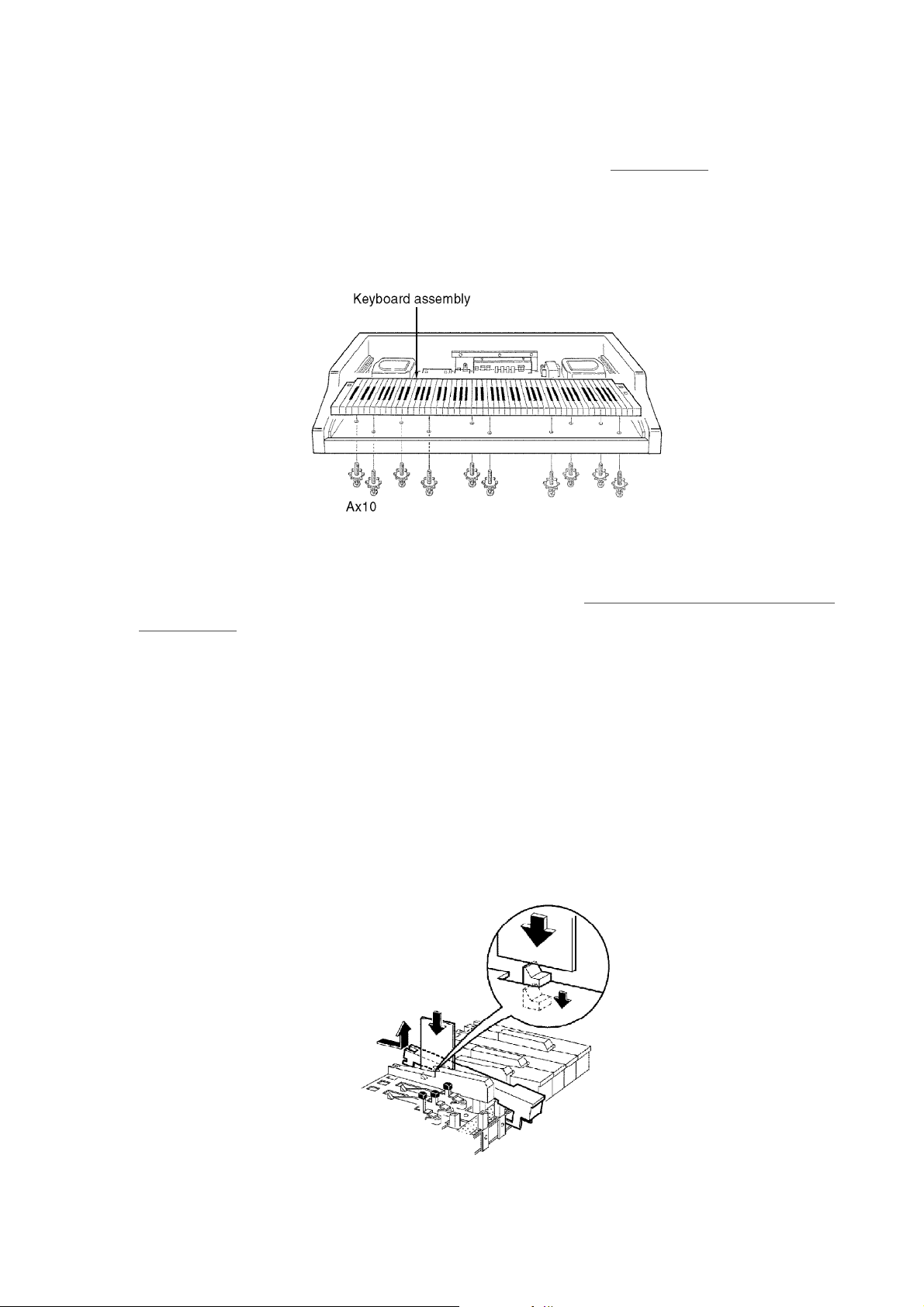
2. Remove the keyboard assembly mounting screws located on the
09/08/2012
www.nostatech.nl
World of free manuals
bottom of the cabinet (A 10 pcs.) as shown in
Figure-10
Figure-10.
7.5. Key(s)
Disassembly
1. Remove the keyboard assembly (see step “Removing the keyboard
assembly”).
2. While inserting a thin plate to press down a claw, push the rear of the
key forward to disengage the key claw from the chassis.
3. Lift the key up to remove it.
Note:
- The key claw is easily broken. Do not apply undue force. Should a key
claw break, it can still be used.
- If a black key is to be replaced, it is necessary to remove both adjacent
white keys.
Figure-11
/ / / /
9
Page 11

Assembly
09/08/2012
www.nostatech.nl
World of free manuals
1. Insert the front part of the key into the chassis.
2. Insert the plate spring into the hammer notch as shown in
Figure -12.
3. While slowly lowering the key into the chassis, insert the plate spring
into the notch at the rear of the key.
4. Carefully insert the key into the opening in the chassis and slide the
key towards the rear to lock it in place.
Figure -12
7.6. Disassembly of the pedal assembly
1. Remove the pedal assembly from the pedal box.
2. Disassemble the pedal assembly as shown in
Figure-13
Figure-13.
7.7. Removing the speakers
Remove the top cover (see step “Removing the top cover”).
Speaker box
10
Page 12
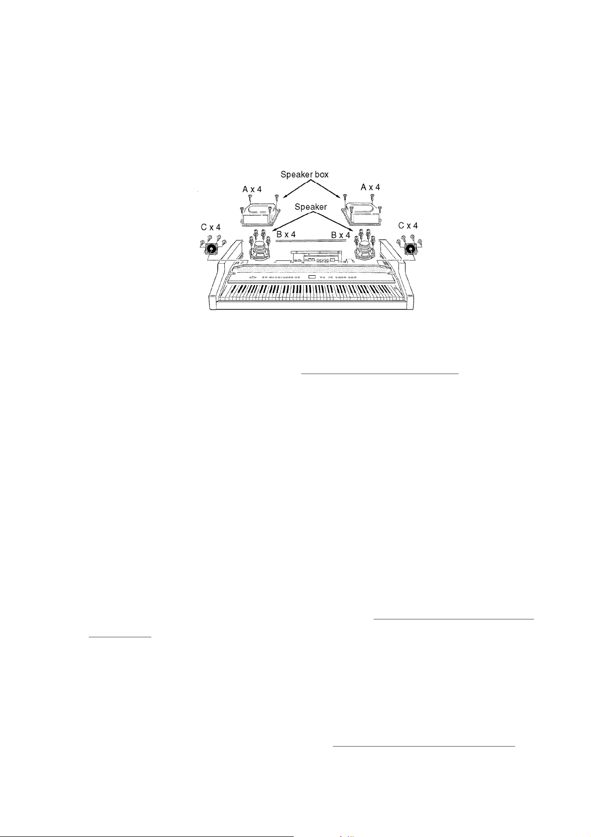
- Remove the speaker box mounting screws (A 4 pcs. each).
09/08/2012
www.nostatech.nl
World of free manuals
Speakers (14 cm)
- Remove the speakers mounting screws (B 4 pcs. each).
Speakers (6.5 cm)
- Remove the speakers mounting screws (C 4 pcs. each).
Figure-14
7.8. Removing the printed circuit boards
- Remove the top cover (see step “
Removing the top cover”).
- Pull out the connectors on the printed circuit boards.
MAIN P.C.B.
1. Remove the ground wire holding screws (A 1pc.).
2. RElease the claws of the 5 P.C.B. holders.
FJASP P.C.B.
1. Remove the FJASP P.C.B. mounting screws (B 2 pcs. and C 2 pcs.).
2. Release the claws of the 3 P.C.B. holders.
COM P.C.B.
1. Remove the COM P.C.B. mounting screws (D 1 pc.).
2. Release the claws of the 2 P.C.B. holders.
HP P.C.B.
1. Remove the keyboard assembly (see step “Removing the keyboard
assembly”).
2. Remove the headphone jack mounting nuts (E 2 pcs.).
3. Remove the ground wire holding screw (F 1 pc.).
4. Remove the HP P.C.B. mounting screws (G 2 pcs.)
CPL P.C.B
1. Remove the control panel (see step “Removing the control panel”).
11
Page 13
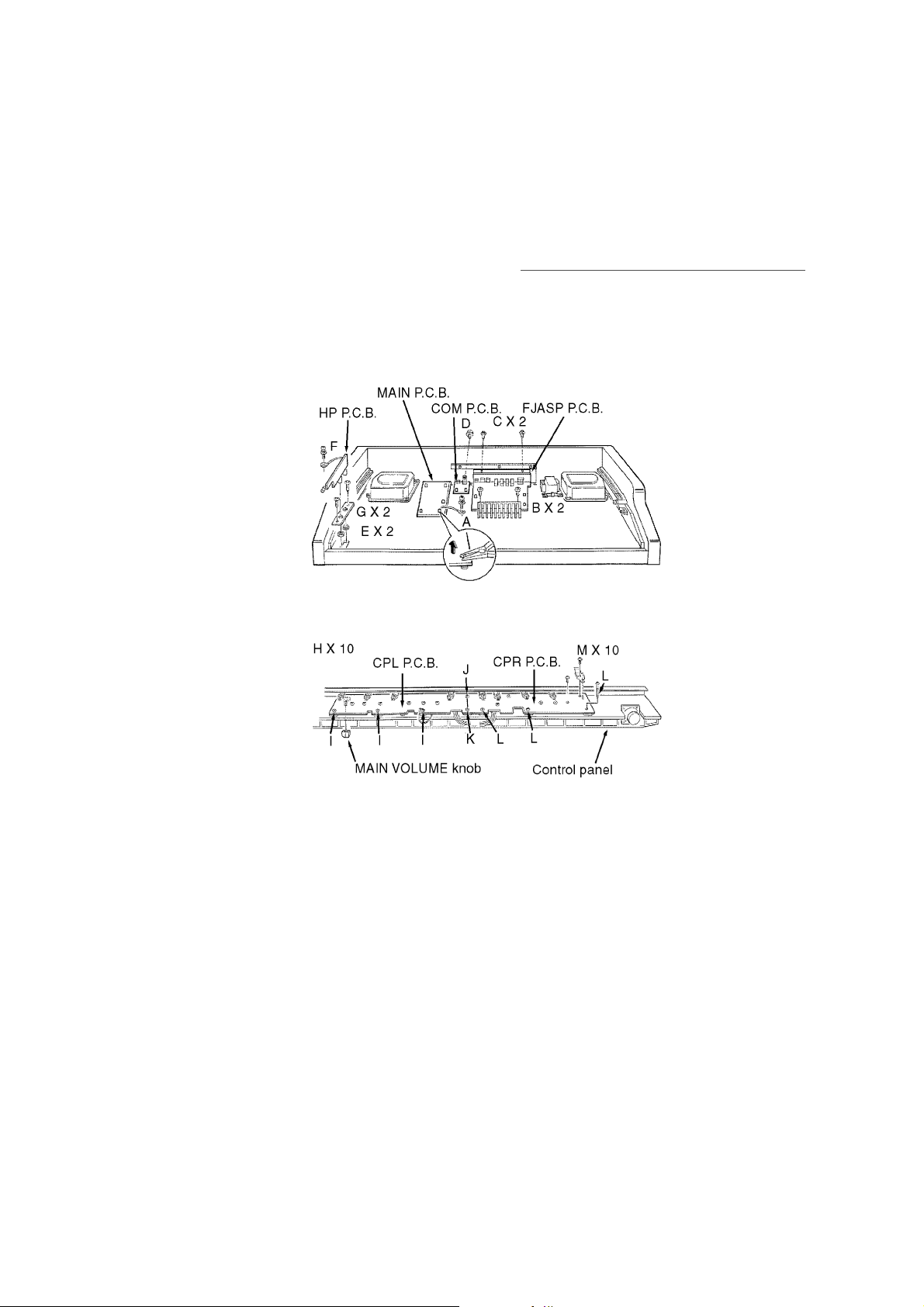
2. Pull the MAIN VOLUME knob.
09/08/2012
www.nostatech.nl
World of free manuals
3. Remove the CPL P.C.B. mounting screws (H 10 pcs., I 3pcs., J 1 pc.,
and K 1 pc.).
CPR P.C.B.
1. Remove the control panel (see step “Removing the control panel”).
2. Remove the CPR P.C.B. mounting screws (M 10 pcs., L 3pcs., J 1 pc.,
and K 1 pc.).
Figure-15
Figure-16
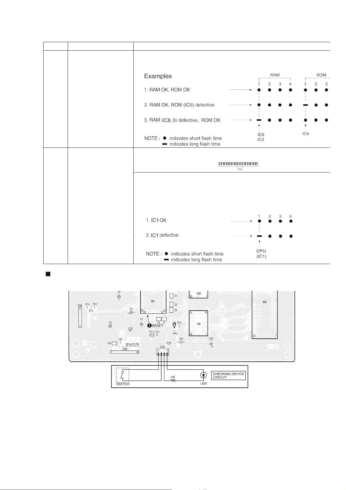
8. SELF-DIAGNOSTIC FUNCTIONS
This model has some self-diagnostic capabilities. When set to the self-diagnostic mode, operation of
various components can be verified by following the procedures in the chart below.
12
Page 14
PCB TEST MODE Procedure
w
E
d
09/08/2012
www.nostatech.nl
World of free manuals
MAIN
RAM (IC8,9), ROM
(IC6) check
1. Connect the CHECKING DEVICE to CN9 on the MAIN P.C.B., and turn on the CHECKING DEVICE s
2. Turn on the power switch.
CPL
CPU (IC1) check
1. Connect the CHECKING DEVICE to CN9 on the MAIN P.C.B. (the Checking Device switch should be
2. Press and hold the two D keys shown below, and then turn on the power switch.
When the power switch is turned on, the LED of the CHECKING DEVIC
flashes 8 times. The first 4 flashes are for the RAM check, and the later
flashes are for the ROM check. The order of the LED flashes correspon
the respective IC numbers as shown below. If an IC is defective, the
corresponding flash time is longer.
Connection between serving CHECKING DEVICE and MAIN P.C.B.
13
Page 15
PCB TEST MODE Procedure
a
a
d
o
e
E
e
y
e
L
09/08/2012
www.nostatech.nl
World of free manuals
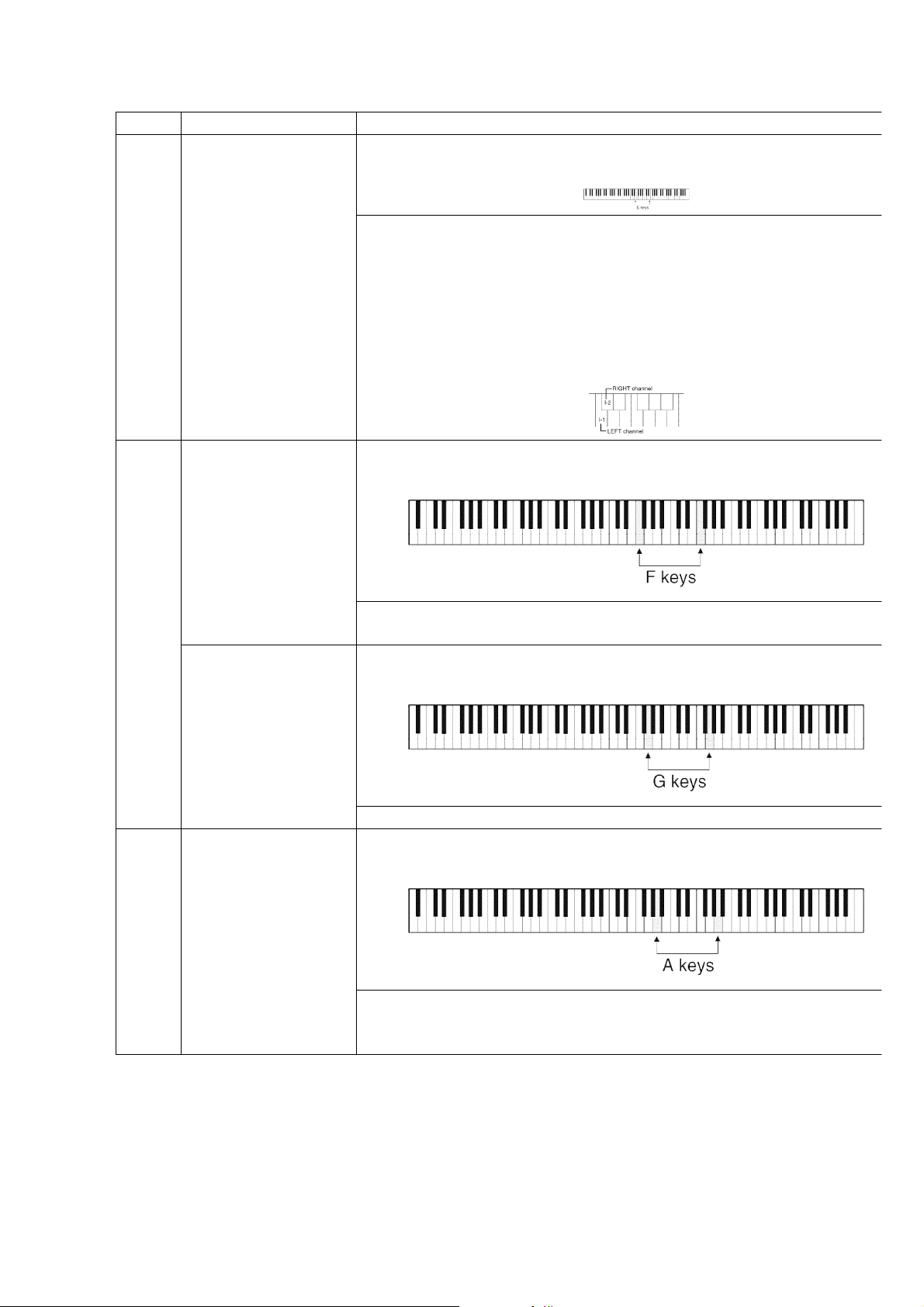
MAIN
Wave ROM check
MAIN: IC12, IC18
1. Press and hold the two E keys shown below, and then turn on the power switch.
2. Select the POP GROUND sound.
3. Reduce the MAIN VOLUME level low enough.
When set to the self-diagnostic mode, the Wave ROM outputs a sine w
The Wave ROMs correspond to the keyboard keys as shown in the
diagram to the right. When a key is pressed, the corresponding sine w
sound is produced. If no sound is produced, or if the sound is distorte
the Wave ROM corresponding to that key is defective. This method all
to diagnose also the output routes (L/R) from the Wave ROM.
-
The key number indicates the Wave ROM number.
(I-1: IC12, I-2: IC18)
CPL
CPR
MKB
Control Panel buttons
LED lighting check
Control Panel LED
display check
Keyboard ROM (IC1)
check
Press and hold the two F keys shown below, and then turn on the pow
switch.
Press the buttons on the control and confirm that the corresponding L
light.
Press and hold the two G keys shown below, and then turn on the pow
switch.
The numbers are displayed automatically and repeatedly on the displa
Press and hold the two A keys shown below, and then turn on the pow
switch.
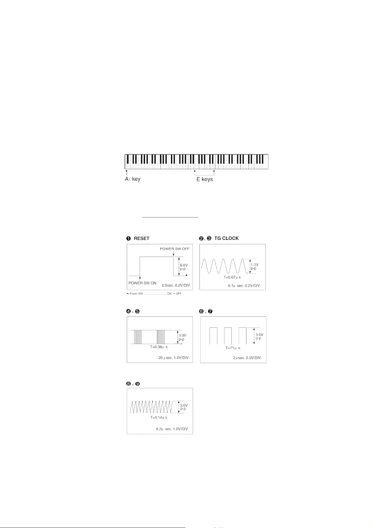
9. PRECAUTIONS BEFORE SERVICING
9.1. Precautions for measuring of the output waveforms
1. The waveform was measured with a “National Digital Storage
If the keyboard ROM (IC1) is OK, only the TOUCH SENSITIVITY LIGHT
flashes. If it is defective, the LEDs (LIGHT and NORMAL, or LIGHT,
NORMAL and HEAVY) flash.
14
Page 16

Oscilloscope VP-5730A”. Therefore the waveforms of musical tone
09/08/2012
www.nostatech.nl
World of free manuals
signals shown may differ somewhat due to the difference in the timing
of triggering.
2. Since the 1/10 test probe is used, the indicated voltage value on the
bottom part of each waveform illustration is 1/10 of the actual value
(e.g. 0.2 V/cm should be 2.0 V/cm).
3. To measure the waveforms, first set this unit to the service diagnostic
mode (refer to “Wave ROM check on
SELF-DIAGNOSTIC FUNCTIONS”).
The WAVE ROM output will then be output as a sine wave to facilitate
the servicing check.
9.2. Important safety notice
- Components identified by a
mark have special characteristics
important for safety.
- When replacing any of these components, use only manufacture’s
specified parts.
9.3. Symbolic marks
The symbolic marks for resistors and capacitors which used in this circuits are classified as following
Table-1 and Table-2.
9.3.1. Resistors
- Resistors without symbolic mark are FIXED CARBON FILM RESISTORS
(ERD-type).
- All resistors are 1/4 WATT, ±5 % TOLERANCE unless otherwise
designated in schematic diagrams.
Table-1
15
Page 17
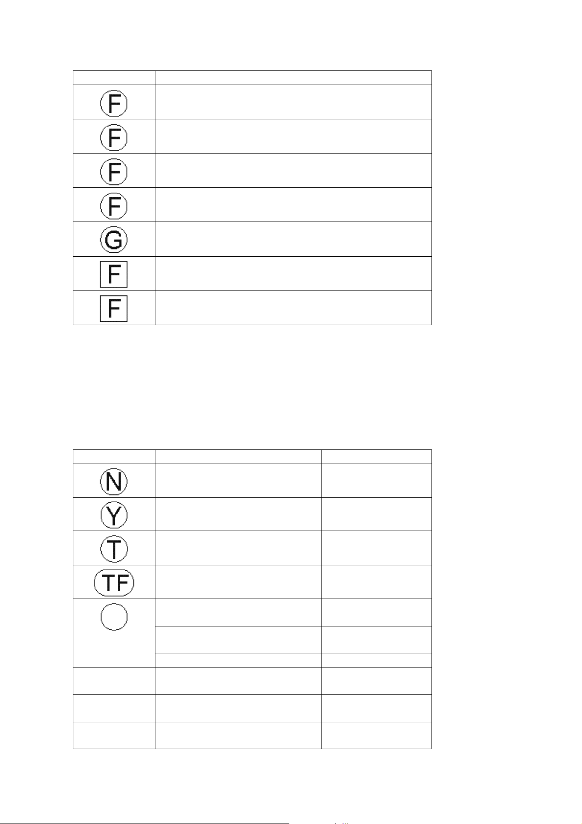
SYMBOL SPECIFICATION
09/08/2012
www.nostatech.nl
World of free manuals
Fixed Carbon Film Resistors
“FLAME-PROOF” (ERD—F—type)
Fixed Wire Wound Resistors
“FLAME-PROOF” (ERF—type)
Fixed Metal Oxide Film Resistors
“FLAME-PROOF” (ERG—type)
Fixed Metal Film Resistors
“FLAME-PROOF” (ERX—type)
Fixed Metal Film Resistors (Precision and High Stability)
(ERO—type)
Fuse Type Fixed Metal Oxide Film Resistors
“FLAME-PROOF” (ERQ—type)
Fuse Type Fixed Carbon Film Resistors
“FLAME-PROOF” (ERD2FC—type)
9.3.2. Capacitors
- Capacitors without symbolic mark are POLYESTER CAPACITORS.
(ECQM-type, ECQG-type, ±10% Tolerance)
- Polarized capacitors without symbolic mark are Aluminum Electrolytic
Capacitors. (ECEA-type, ±20% Tolerance)
Table-2
SYMBOL SPECIFICATION TYPE
Non-Polarized Electrolytic
Capacitors
Non-Polarized Electrolytic (for
Network system)
Tantalum Solid Electrolytic
Capacitors
Metallized Plastic Film Capacitors
(TF Series)
Temperature Compensating
Ceramic Capacitors
High-Dielecytric Constant Ceramic
Capacitors
Axial Lead Ceramic Capacitors ECB_type
Metallized Polyester Film
Capacitors for Across the Line
Aluminum Electrolytic Capacitors
for Smoothing Circuit
Multilayer Ceramic Chip
Capacitors
ECEA_KN_type
ECEA_Y_type
ECS_type
ECQV_type
ECC_type
ECK_type, ECR_type
ECQ_EW_type
ECES_type
ECUV_type
16
Page 18
10. MEASURING CONDITION
09/08/2012
www.nostatech.nl
World of free manuals
10.1. Measuring condition of MAIN P.C.B.
Check Point 2 - 9
Set to the Self-diagnostic Mode followings.
- While pressing two E keys simultaneously, turn on the power switch.
- SOUND: CONCERT GRAND
- MAIN VOLUME: Max.
- Keyboard: A
Check Point 1
Set to the Initial mode (refer to “
1
OWNERS MANUAL”).
10.2. Measuring condition of FAJSP P.C.B.
Check Point 3 - 8
Set to the Self-diagnostic Mode followings.
17
Page 19
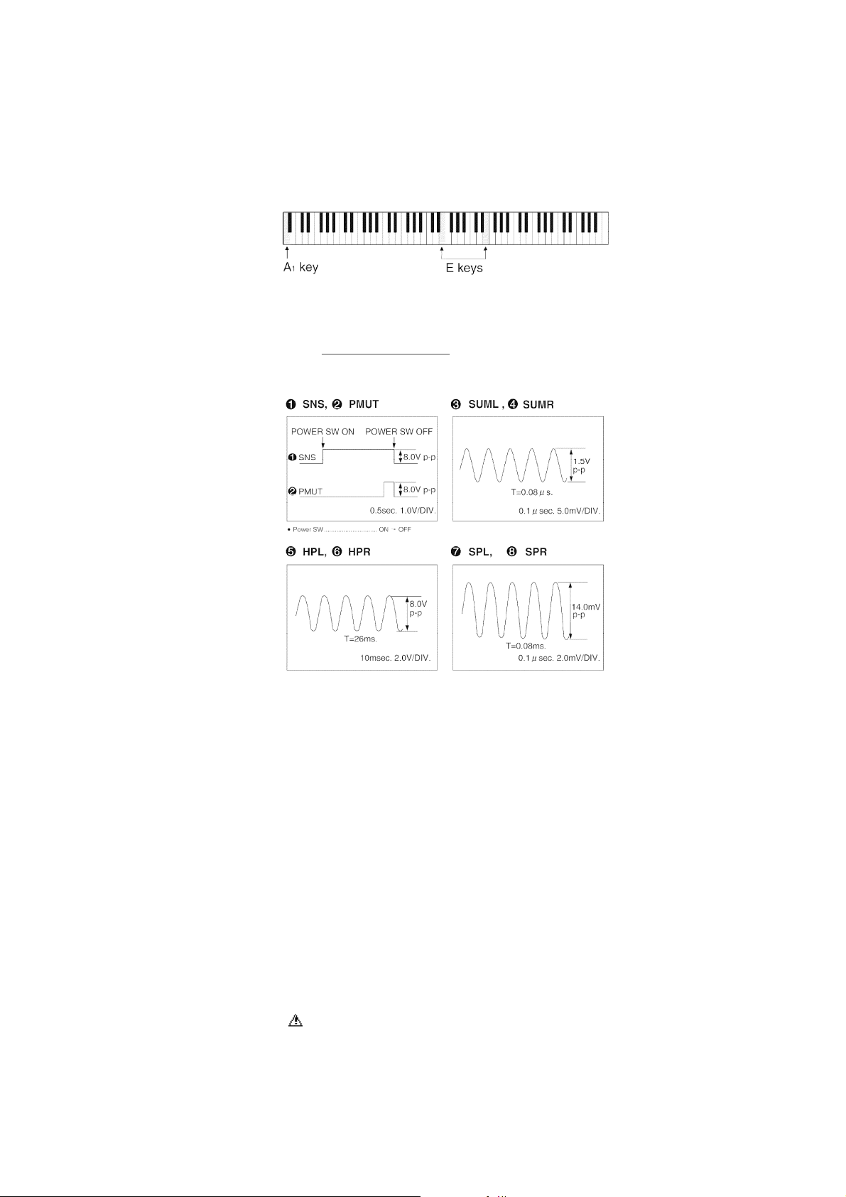
- While pressing two E keys simultaneously, turn on the power switch.
09/08/2012
www.nostatech.nl
World of free manuals
- SOUND: CONCERT GRAND
- MAIN VOLUME: Max.
- Keyboard: A
Check Point 1,2
Set to the Initial mode (refer to “
1
OWNERS MANUAL”).
11. SCHEMATIC DIAGRAM
12. PRINTED CIRCUIT BOARD
12.1. MAIN, FAJSP, CPL P.C.B.
12.2. CPR, MKB1, MKB2, PKB, COM, HP P.C.B.
13. BLOCK DIAGRAM
14. WIRING CONNECTION DIAGRAM
15. REPLACEMENT PARTS LIST
Notes:
*Important safety notice:
Components identified by
Furthermore, special parts which have purposes of fire-retardant (resistors), high-quality sound
(capacitors), low-noise (resistors), etc. are used.
When replacing any of components, be sure to use only manufacture’s specified parts shown in the
mark have special characteristics important for safety.
18
Page 20

parts list.
09/08/2012
www.nostatech.nl
World of free manuals
*Warning: This product uses a laser diode. Refer to caution statements.
*ACHTUNG: Die lasereinheit nicht zerlegen. Die lasereinheit darf nur gegen einc vom hersteller
spezifizierte einheit ausgetauscht werden.
*Capacity values are in microfarads (uF) unless specified otherwise. P=Pico-farads (pF), F=farads (F)
*Resistance values are in ohms, unless specified otherwise. 1K=1,000 (OHM), 1M=1,000K (OHM)
*The marking <RTL> indicates that the Retention Time is limited for this item. After the
discontinuation of this assembly in production, the item will continue to be available for a specific
period of time. The retention period of availability is dependant on the type of assembly, and in
accordance with the laws governing part and product retention. After the end of this period, the
assembly will no longer be available.
*”<IA>”-”<IH>” marks in Remarks indicate languages of instruction manuals. [<IA>: Dansk, <IB>:
English, <IC>: English, <ID>: French, <IE>: Germany, <IF>: Italiano, <IG> : Espanol, <IH>: Nederlands]
*MAIN, FAJSP, CPL, CPR, MKB1, MKB2, COM and HP in Remarks indicate the Circuits and P. C. B.s. If
the same Ref. No. is found in the replacement parts list, check those indications in the Remarks.
Ref. No. Part No. Part Name & Description
1 QAQG032AAK SOUND LOOPHOLE BOARD 1
2 QGPG0136BA CONTROL PANEL 1
3 SBNG7050A KNOB 1
4 QMFG1107AA FELT(RED) 1
5 QGPG0106AA LED PANEL 1
6 QMRG5229AA CUSHION 1
7 QMRG5230AA CUSHION 1
8 QGPG0123DA BUTTON 1
9 QGPG0124AB BUTTON 1
10 QMCG004AA SPACER 9
11 QKSGG030AAK GUIDE 1
12 QKSGG031AAK GUIDE 1
13 SJS9231A AC INLET COVER 1
13 SJS9334A AC INLET COVER 1
14 QMRG5155AAK CUSHION 4
15 QMRG5206AA CUSHION 1
16 SHRG1230A CORD CLAMPER 1
17 QLZG021A CORE 3
18 QMRG7086AA LID,GUIDE 2
19 QYKG261AAZ CABINET ASS'Y 1
19 QYKG261ABZ CABINET ASS'Y 1 SX-PX554M
20 QMFG1083AB FELT 1
21 SBLG7-2 STAY 1
22 QKQGN926AAZ MUSIC STAND 1
22 QKQGN926ABZ MUSIC STAND 1 SX-PX554M
23 SBHG5003-2 HINGE 2
24 QKQGA142ACZ TOP COVER ASS'Y 1
24 QKQGA142ADZ TOP COVER ASS'Y 1 SX-PX554M
24-1 QMFG1274AA FELT 1
24-2 SGBG160B BADGE 1
25 QKQGF037BAZ KEYBOARD COVER ASS'Y 1
25 QKQGF037BEZ KEYBOARD COVER ASS'Y 1 SX-PX554M
25-1 QMRG7098AA HOLDER 2
25-2 QWBG002AA HOLDER 1
25-3 QXQG007AA AXLETREE 1
25-4 QGKG0154AA ORNAMENT 1
Pcs
EXCEPT P, PC, PY
P, PC ,PY ONLY
Remarks
19
Page 21
Ref. No. Part No. Part Name & Description
09/08/2012
www.nostatech.nl
World of free manuals
25-4 QGKG0154AB ORNAMENT 1 SX-PX554M
25-5 QMRG7031EC PROTECTOR 1
25-6 QMRG7032EC PROTECTOR 1
25-7 QMFG1277AA FELT 2
25-8 QGKG0095AD ORNAMENT 1
26 QKQGN998AAZ CROSS BOARD 1
26 QKQGN998ABZ CROSS BOARD 1 SX-PX554M
27 SHRG9620A CORD CLAMPER 3
28 QKQGM107AAZ PANEL BOX ASS'Y 1
28 QKQGM105ABZ PEDAL BOX ASS'Y 1 SX-PX554M
28-1 QGKG0113AA ORNAMENT 3
29 QKQGN995AAZK LEFT PLANK 1
29 QKQGN995ABZK LEFT PLANK 1 SX-PX554M
30 QKQGN996AAZK RIGHT PLANK 1
30 QKQGN996ABZK RIGHT PLANK 1 SX-PX554M
31 QAQG033AAK LEFT LEG ASS'Y 1
31 QAQG033ABK LEFT LEG ASS'Y 1 SX-PX554M
31-1 SHRG2130B-K FOOT 2
31-2 XTB4+16A SCREW 4
32 QAQG034AAK RIGHT LEG ASS'Y 1
32 QAQG034ABK RIGHT LEG ASS'Y 1 SX-PX554M
32-1 SHRG2130B-K FOOT 2
32-2 XTB4+16A SCREW 4
33 QMWG4002AA PEDAL ARM 3
34 QMFG1134AA FELT 3
35 QMBG009AA SPRING 3
36 QMFG1133AA FELT 3
37 QKAG0011AA FOOT 1
38 QMFG1135AA FELT 3
39 SGKG980A LABEL 1
40 QTPG1N017A POWER TRANSFORMER 1
40 QTPG1N022A POWER TRANSFORMER 1
41 QGUG1040AA BUTTON,POWER SW 1
42 QGPG0139AB END COVER PANEL,LEFT 1
43 QGPG0138AB END COVER PANEL,RIGHT 1
44 QMFG1104AA FELT 1
45 QMWG1041AA WHITE KEY(FIRST OCTAVE A 1
46 QMWG1042AA WHITE KEY(B KEY) 8
47 QMWG1043AA WHITE KEY(C KEY) 7
48 QMWG1044AA WHITE KEY(D KEY) 7
49 QMWG1045AA WHITE KEY(E KEY) 7
50 QMWG1046AA WHITE KEY(F KEY) 7
51 QMWG1047AA WHITE KEY(G KEY) 7
52 QMWG1048AA WHITE KEY(A KEY) 7
53 QMWG1049AA WHITE KEY(TOP OCTAVE C KE 1
54 QMWG2006AA BLACK KEY 36
55 QMCG011BA SPRING 88
56 QMWG9027AA HAMMER(BLACK KEY) 8
57 QMWG9027AB HAMMER(BLACK KEY) 14
58 QMWG9027AC HAMMER(BLACK KEY) 7
59 QMWG9027AD HAMMER(BLACK KEY) 7
60 QMWG9025AA HAMMER(WHITE KEY) 12
61 QMWG9025AB HAMMER(WHITE KEY) 19
62 QMWG9025AC HAMMER(WHITE KEY) 11
63 QMWG9025AD HAMMER(WHITE KEY) 10
64 QMGG060AA RUBBER CAP(HAMMER) 88
Pcs
EXCEPT P PC, PY
P, PC, PY ONLY
Remarks
20
Page 22

Ref. No. Part No. Part Name & Description
09/08/2012
www.nostatech.nl
World of free manuals
65 QMWG8045AA KEY GUIDE 88
66 QMWG8041AA FUL CU RUM(4 PCS,ON ONE) 1
67 QMWG8040AA FUL CU RUM(12 PCS,ON ONE) 7
68 QMFG1267BA FELT 2
69 QMFG1268BA FELT 2
70 QMFG1266BA FELT 4
71 QMFG1265AA FELT 2
72 QMWG6021AA RUBBER SWITCH(4 PCS,ON ON 1
73 QMWG6020AA RUBBER SWITCH(12 PCS,ON O 7
74 XNS12FZ NUT 2
75 XTT4+10A SCREW 16
76 XTB4+12A SCREW 4
77 XTW3+8J SCREW 1
78 XTN4+16F SCREW WITH WASHER 1
79 XTT4+14A SCREW 2
80 XTB35+14A SCREW 1
81 XYN4+F16FZ SCREW 3
82 XTB35+10A SCREW 3
83 XTW3+10Q SCREW 28
84 XTV3+20JFZ SCREW 7
85 XTT4+12AFZ SCREW 2
86 XYA35+JA12 SCREW 14
87 XYN3+C8FZ SCREW 1
88 XTV3+10JFZ SCREW 3
89 XTWSG2 SCREW 8
90 XYN4+F16 SCREW 4
91 XTT4+20A SCREW 8
92 QHDG021AA SCREW 10
93 QHWG007AA NUT 2
94 QHDG055AA SCREW 12
95 XTT4+25A SCREW 6
96 GTT4+25AFZ SCREW 4
97 XTB3+10AFZ SCREW 3
98 XTB35+16A SCREW 10
99 XTN4+50AFZ SCREW 2
100 QHDG032AB SCREW WITH WASHER 4
101 QHDG016AB SCREW WITH WASHER 6
102 XTS3+12AFZ SCREW 6
103 XTS3+10AFZ SCREW 4
104 XTT5+20AFZ SCREW 4
105 XTV3+20JFZ SCREW 2
106 XTV3+12G SCREW 4
107 XTW3+10T SCREW
108 QMWG8038AA HAMMER SUPPORT(WHITE KEY) 52
109 QMWG8039AA HAMMER SUPPORT(BLOCK KEY) 36
16
Pcs
Remarks
A1 QQFGPX552AA FANBAG 1 P
A1 QQFGPX552CA FANBAG 1 EX X PY XA
A1 QQFGPX552DA FANBAG 1 PC
A1 QQFGPX552EA FANBAG 1 EB,GN
A1 QQFGPX552FA FANBAG 1 EZ
A1 QQFGPX552GA FANBAG 1 EG
A2 QJAG025AA AC CORD 1
A2 QJAG027AA AC CORD 1
A2 QJAG028AA AC CORD 1
P,PC,PY
EZ EG EX X
EB
21
Page 23

Ref. No. Part No. Part Name & Description
09/08/2012
www.nostatech.nl
World of free manuals
A2 QJAG029AA AC CORD 1
A2 QJAG031AA AC CORD 1
A3 SJP5213-2 ATTACHMENT PULG 1
C1 ECEA0JKS101B 100UF,6.3V 1 CPL
C1 ECKCVA1472MF 4700PF 1
C1
C1 ECKF1E473ZV 0.047UF 1 HP
C1 ECRF1H104ZF 0.1UF 1 MKB1
C1 ECUV1C224KBX 0.22UF 1 MAIN
C2 ECKF1E473ZV 0.047UF 1 HP
C2 ECQU2A104MN 0.1UF,250V 1
C2 ECUV1C224KBX 0.22UF 1 MAIN
C2 QCBG1H104ZFA 0.1UF 1 CPL
C3 ECBT1E223ZF5 0.022UF 1 CPL
C3 ECRF1H104ZF 0.1UF 1 HP
C3 ECRR1H104ZF1 0.1UF 1 MAIN
C4 ECA1VM472E 4700UF,35V 1 FJASP
C4 ECEA0JKA470 47UF,6.3V 1 MKB1
C4 ECEA0JKS101B 100UF,6.3V 1 CPL
C4 ECEA1HKA010B 1UF,50V 1 MAIN
C5 ECRF1H104ZF 0.1UF 1 MKB2
C6 ECRF1H104ZF 0.1UF 1 MKB1
C6 ECA1VM472E 4700UF,35V 1 FJASP
C6 ECUV1H101JG 100PF 1 MAIN
C7 ECRF1H104ZF 0.1UF 1 MKB2
C7 ECUV1H101JG 100PF 1 MAIN
C7 QCBG1H104ZFA 0.1UF 1 CPL
C8 ECCR1H104ZF1 0.1UF 1 FJASP
C8 ECUV1H104ZFX 0.1UF 1 MAIN
C9 ECCR1H104ZF1 0.1UF 1 FJASP
C9 ECUV1H104ZFX 0.1UF 1 MAIN
C10 ECEA1CKA100B 10UF,16V 1 FJASP
C10 ECUV1H104ZFX 0.1UF 1 MAIN
C10 QCBG1H104ZFA 0.1UF 1 CPL
C11 ECA1CM331B 330UF,16V 1 FJASP
C11 ECUV1H104ZFX 0.1UF 1 MAIN
C12 ECEA1HKN010B 1UF,50V 1 FJASP
C13 ECCR1H221J5 220PF 1 FJASP
C13 ECUV1H101JG 100PF 1 MAIN
C14 ECEA1HKN010B 1UF,50V 1 FJASP
C14 ECUV1H101JG 100PF 1 MAIN
C15 ECCR1H221J5 220PF 1 FJASP
C15 ECUV1H104ZFX 0.1UF 1 MAIN
C16 ECQB1H103JF3 0.01UF 1 FJASP
C16 ECUV1H104ZFX 0.1UF 1 MAIN
C17 ECQV1H474JM3 0.47UF 1 FJASP
C17 ECUV1H104ZFX 0.1UF 1 MAIN
C18 ECQG1H152KZT 0.0015UF 1 FJASP
C19 ECEA1HKN010B 1UF,50V 1 FJASP
C19 ECUV1H104ZFX 0.1UF 1 MAIN
C20 ECQB1H473JF3 0.047UF 1 FJASP
C20 ECUV1C224KBX 0.22UF 1 MAIN
C21 ECQB1H333JF3 0.033UF 1 FJASP
C22 ECQG1H472KZT 0.0047UF 1 FJASP
ECRR1H104ZF
0.1UF 1 PKB
Pcs
GN
XA
X
FJASP
FJASP
Remarks
22
Page 24

Ref. No. Part No. Part Name & Description
09/08/2012
www.nostatech.nl
World of free manuals
C23 ECQV1H683JM3 0.068UF 1 FJASP
C23 ECUV1H102JX 0.001UF 1 MAIN
C24 ECQB1H223JF3 0.022UF 1 FJASP
C24 ECUV1H101JG 100PF 1 MAIN
C25 ECQB1H153JF3 0.015UF 1 FJASP
C25 ECUV1H101JG 100PF 1 MAIN
C26 ECQG1H682KZT 0.0068UF 1 FJASP
C26 ECUV1H104ZFX 0.1UF 1 MAIN
C27 ECQG1H332KZT 0.0033UF 1 FJASP
C27 ECUV1H104ZFX 0.1UF 1 MAIN
C28 ECEA1CKA470B 47UF,16V 1 MAIN
C28 ECQG1H222KZT 0.0022UF 1 FJASP
C29 ECQB1H103JF3 0.01UF 1 FJASP
C29 EECS5R5V105 1F,5.5V 1 MAIN
C30 ECEA1HKN010B 1UF,50V 1 FJASP
C30 ECUV1H104ZFX 0.1UF 1 MAIN
C31 ECQB1H473JF3 0.047UF 1 FJASP
C32 ECQV1H474JM3 0.47UF 1 FJASP
C33 ECQG1H152KZT 0.0015UF 1 FJASP
C34 ECQV1H683JM3 0.068UF 1 FJASP
C35 ECQB1H223JF3 0.022UF 1 FJASP
C36 ECQB1H333JF3 0.033UF 1 FJASP
C36 ECUV1H104ZFX 0.1UF 1 MAIN
C37 ECQG1H472KZT 0.0047UF 1 FJASP
C37 ECUV1H104ZFX 0.1UF 1 MAIN
C38 ECQB1H153JF3 0.015UF 1 FJASP
C38 ECUV1H104ZFX 0.1UF 1 MAIN
C39 ECQG1H682KZT 0.0068UF 1 FJASP
C39 ECUV1H104ZFX 0.1UF 1 MAIN
C40 ECQG1H332KZT 0.0033UF 1 FJASP
C40 ECUV1H104ZFX 0.1UF 1 MAIN
C41 ECQG1H222KZT 0.0022UF 1 FJASP
C41 ECUV1H104ZFX 0.1UF 1 MAIN
C42 ECCR1H100D5 10PF 1 FJASP
C42 ECUV1H104ZFX 0.1UF 1 MAIN
C43 ECCR1H100D5 10PF 1 FJASP
C43 ECUV1H104ZFX 0.1UF 1 MAIN
C44 ECQV1H154JM3 0.15UF 1 FJASP
C44 ECUV1H104ZFX 0.1UF 1 MAIN
C45 ECQB1H223JF3 0.022UF 1 FJASP
C45 ECUV1H104ZFX 0.1UF 1 MAIN
C46 ECQV1H104JM3 0.1UF 1 FJASP
C46 ECUV1H104ZFX 0.1UF 1 MAIN
C47 ECEA50Y1R5K 1.5UF,50V 1 FJASP
C47,48 ECUV1H104ZFX 0.1UF 2 MAIN
C49 ECQV1H154JM3 0.15UF 1 FJASP
C49 ECUV1H104ZFX 0.1UF 1 MAIN
C50 ECQB1H223JF3 0.022UF 1 FJASP
C50 ECUV1H104ZFX 0.1UF 1 MAIN
C51 ECQV1H104JM3 0.1UF 1 FJASP
C51 ECUV1H104ZFX 0.1UF 1 MAIN
C52 ECEA50Y1R5K 1.5UF,50V 1 FJASP
C54 ECBT1C222MR5 0.0022UF 1 FJASP
C54 ECUV1H104ZFX 0.1UF 1 MAIN
C55 ECBT1C222MR5 0.0022UF 1 FJASP
C55 ECUV1H104ZFX 0.1UF 1 MAIN
C56 ECCR1H104ZF1 0.1UF 1 FJASP
Pcs
Remarks
23
Page 25

C56
ECCR1H104ZF1
0.1UF1FJASP
09/08/2012
www.nostatech.nl
World of free manuals
24
Page 26

Ref. No. Part No. Part Name & Description
09/08/2012
www.nostatech.nl
World of free manuals
C56 ECUV1H104ZFX 0.1UF 1 MAIN
C57 ECCR1H104ZF1 0.1UF 1 FJASP
C57 ECUV1H104ZFX 0.1UF 1 MAIN
C58 ECBT1C222MR5 0.0022UF 1 FJASP
C58 ECUV1H104ZFX 0.1UF 1 MAIN
C59 ECBT1C222MR5 0.0022UF 1 FJASP
C60 ECCR1H104ZF1 0.1UF 1 FJASP
C60 ECUV1H104ZFX 0.1UF 1 MAIN
C62 ECEA1CKA100B 10UF,16V 1 MAIN
C63,64 ECUV1H104ZFX 0.1UF 2 MAIN
C65 ECCR1H221J5 220PF 1 FJASP
C65 ECEA1CKA100B 10UF,16V 1 MAIN
C66 ECEA1HKNR47B 0.47UF,50V 1 MAIN
C66 ECKR1E473ZV 0.047UF 1 FJASP
C67 ECEA1HKA010B 1UF,50V 1 FJASP
C67 ECEA1HKNR47B 0.47UF,50V 1 MAIN
C73 ECCR1H104ZF1 0.1UF 1 FJASP
C77 ECUV1H104ZFX 0.1UF 1 MAIN
C78-82 ECUV1H101JG 100PF 5 MAIN
C83 ECUV1H104ZFX 0.1UF 1 MAIN
C84 ECEA0JKA101B 100UF,6.3V 1 MAIN
C85,86 ECUV1H101JG 100PF 2 MAIN
C87 ECRR1H104ZF1 0.1UF 1 MAIN
C88 ECA1VM470B 47UF,35V 1 MAIN
C89 ECRR1H104ZF1 0.1UF 1 MAIN
C90 ECUV1H101JG 100PF 1 MAIN
C91 ECA0JM102B 1000UF,6.3V 1 MAIN
C92 ECUV1H102JX 0.001UF 1 MAIN
C95 ECUV1H102JX 0.001UF 1 MAIN
C98 ECEA1CKA100B 10UF,16V 1 MAIN
C99,00 ECUV1H104ZFX 0.1UF 2 MAIN
C101 ECEA1CKA100B 10UF,16V 1 MAIN
C105,06 ECEA1HKNR47B 0.47UF,50V 2 MAIN
C107 ECUV1H101JG 100PF 1 MAIN
C108 ECRR1H104ZF1 0.1UF 1 MAIN
C109 ECUV1H101JG 100PF 1 MAIN
C110 ECRR1H104ZF1 0.1UF 1 MAIN
C111 ECUV1H104ZFX 0.1UF 1 MAIN
C116 ECEA0JKA101B 100UF,6.3V 1 MAIN
C117 ECUV1H104ZFX 0.1UF 1 MAIN
C120,21 ECUV1H221JG 220PF 2 MAIN
Pcs
Remarks
CN1 SJPG1JS120A CONNECTOR 1 MAIN
CN1 SJPG2JS050A CONNECTOR 1 CPL
CN1 SJPG7JS020A CONNECTOR 1 FJASP
CN2 SJPG1JS060A CONNECTOR 1 MAIN
CN2 SJPG2JS160A CONNECTOR 1 CPL
CN2 SJPG7JS040A CONNECTOR 1 FJASP
CN3 SJPG1JS050A CONNECTOR 1 MAIN
CN3 SJPG1JS160A CONNECTOR 1 MKB1
CN3 SJPG2JS160A CONNECTOR 1 CPR
CN3 SJPG7JS030A CONNECTOR 1 FJASP
CN4 QJJG01812AA CONNECTOR 1 MKB2
CN4 SJPG1JS060A CONNECTOR 1 FJASP
CN4 SJPG1JS160A CONNECTOR 1 MAIN
CN4 SJPG2JS060A CONNECTOR 1 CPL
CN5 SJPG1JS120A CONNECTOR 1 FJASP
25
Page 27
CN5
SJPG1JS120A
CONNECTOR
1
FJASP
Ref. No. Part No. Part Name & Description
09/08/2012
www.nostatech.nl
World of free manuals
CN6 SJPG1JS070A CONNECTOR 1 MAIN
CN6 SJPG1JS070A CONNECTOR 1 FJASP
CN7 SJPG1310A CONNECTOR 1 FJASP
CN8 QJUG00212AA CONNECTOR 1 MKB1
CN8 SJPG1340A CONNECTOR 1 FJASP
CN8 SJPG1JS100A CONNECTOR 1 MAIN
CN9 QJUG01408AA CONNECTOR 1 MKB1
CN9 SJPG1JS040A CONNECTOR 1 MAIN
Pcs
Remarks
D1 ERA1502V5 DIODE 1
D1 MA165 DIODE 1 MKB1
D1 MA165TA5 DIODE 1 CPR
D1 MA8030HTX Z.DIODE 1 MAIN
D1 SEL4214RLC05 LED,POWER INDICATOR 1 HP
D2 ERA1502V5 DIODE 1
D2 MA111TX DIODE 1 MAIN
D2 MA165 DIODE 1 MKB1
D2 MA165TA5 DIODE 1 CPR
D3 MA111TX DIODE 1 MAIN
D3 MA165 DIODE 1 MKB1
D3 SVDGS3V20-15 RECTIFIER 1
D4 MA165 DIODE 1 MKB1
D4 SVDGS3V20-15 RECTIFIER 1
D5 MA165 DIODE 1 MKB1
D5 SVDGS3V20-15 RECTIFIER 1
D6 MA165 DIODE 1 MKB1
D6 SVDGS3V20-15 RECTIFIER 1
D7 MA165 DIODE 1 MKB1
D7 SVDGS3V20-15 RECTIFIER 1
D8 MA111TX DIODE 1 MAIN
D8 MA165 DIODE 1 MKB1
D8 SVDGS3V20-15 RECTIFIER 1
D9 MA111TX DIODE 1 MAIN
D9 MA165 DIODE 1 MKB1
D9 MA165TA5 DIODE 1 CPR
D9 SVDGS3V20-15 RECTIFIER 1
D10 MA111TX DIODE 1 MAIN
D10 MA165 DIODE 1 MKB1
D10 MA165TA5 DIODE 1 CPR
D10 SVDGS3V20-15 RECTIFIER 1
D11 MA111TX DIODE 1 MAIN
D11 MA165 DIODE 1 MKB1
D11 MA4180TA ZENER,18V 1 FJASP
D12 MA111TX DIODE 1 MAIN
D12 MA165 DIODE 1 MKB1
D12 MA4180TA ZENER,18V 1 FJASP
D13 EK04W DIODE 1 FJASP
D13 MA111TX DIODE 1 MAIN
D13 MA165 DIODE 1 MKB1
D14 EK04W DIODE 1 FJASP
D14 MA111TX DIODE 1 MAIN
D14,15 MA165 DIODE 2 MKB1
D15 MA165TA5 DIODE 1 FJASP
;FJASP
FJASP
FJASP
FJASP
FJASP
FJASP
FJASP
FJASP
FJASP
FJASP
26
Page 28

Ref. No. Part No. Part Name & Description
09/08/2012
www.nostatech.nl
World of free manuals
D15 MA8056MTX ZENER 1 MAIN
D16 MA165 DIODE 1 MKB1
D16 MA165TA5 DIODE 1 FJASP
D16 MA8047HTX Z.DIODE 1 MAIN
D17 MA111TX DIODE 1 MAIN
D17 MA165 DIODE 1 MKB1
D17 MA165TA5 DIODE 1 FJASP
D17 MA165TA5 DIODE 1 CPR
D18 MA111TX DIODE 1 MAIN
D18 MA165 DIODE 1 MKB1
D18 MA165TA5 DIODE 1 CPR
D19 EK04W DIODE 1 MAIN
D19,20 MA165 DIODE 2 MKB1
D20 MA2062LF ZENER,6.2V 1
D21 MA111TX DIODE 1 MAIN
D21 MA165 DIODE 1 MKB1
D22 MA111TX DIODE 1 MAIN
D22 MA165 DIODE 1 MKB1
D22 MA165TA5 DIODE 1 FJASP
D23 MA111TX DIODE 1 MAIN
D23 MA165 DIODE 1 MKB1
D23 MA165TA5 DIODE 1 FJASP
D24 MA111TX DIODE 1 MAIN
D24 MA165 DIODE 1 MKB1
D25 MA111TX DIODE 1 MAIN
D25 MA165 DIODE 1 MKB1
D25 MA165TA5 DIODE 1 CPR
D26 MA111TX DIODE 1 MAIN
D26 MA165 DIODE 1 MKB1
D26 MA165TA5 DIODE 1 CPR
D27 MA111TX DIODE 1 MAIN
D27 MA165 DIODE 1 MKB1
D28 MA111TX DIODE 1 MAIN
D28 MA165 DIODE 1 MKB1
D29 MA111TX DIODE 1 MAIN
D29,30 MA165 DIODE 2 MKB1
D30 MA165TA5 DIODE 1 FJASP
D31 MA111TX DIODE 1 MAIN
D31 MA165 DIODE 1 MKB1
D31 MA165TA5 DIODE 1 FJASP
D32 MA1039HTR Z.DIODE 1 MAIN
D32 MA165 DIODE 1 MKB1
D32 MA165TA5 DIODE 1 FJASP
D33 MA165 DIODE 1 MKB1
D33 MA165TA5 DIODE 1 CPR
D34 MA165 DIODE 1 MKB1
D34 MA165TA5 DIODE 1 CPR
D35-41 MA165 DIODE 7 MKB1
D41 MA165TA5 DIODE 1 CPR
D42 MA165 DIODE 1 MKB1
D42 MA165TA5 DIODE 1 CPR
D43-49 MA165 DIODE 7 MKB1
D49 MA165TA5 DIODE 1 CPR
D50-59 MA165 DIODE 10 MKB1
D59 MA165TA5 DIODE 1 CPL
D60 MA165 DIODE 1 MKB1
Pcs
MAIN
Remarks
27
Page 29

Ref. No. Part No. Part Name & Description
09/08/2012
www.nostatech.nl
World of free manuals
D60 MA165TA5 DIODE 1 CPL
D61-65 MA165 DIODE 5 MKB1
D65 MA165TA5 DIODE 1 CPL
D66 MA165 DIODE 1 MKB1
D66 MA165TA5 DIODE 1 CPL
D67 MA165 DIODE 1 MKB1
D67 MA165TA5 DIODE 1 CPL
D68 MA165 DIODE 1 MKB1
D68 MA165TA5 DIODE 1 CPL
D69-73 MA165 DIODE 5 MKB1
D73 MA165TA5 DIODE 1 CPL
D74 MA165 DIODE 1 MKB1
D74 MA165TA5 DIODE 1 CPL
D75 MA165 DIODE 1 MKB1
D75 MA165TA5 DIODE 1 CPL
D76 MA165 DIODE 1 MKB1
D76 MA165TA5 DIODE 1 CPL
D77 MA165 DIODE 1 MKB1
D77 MA165TA5 DIODE 1 CPL
D78-81 MA165 DIODE 4 MKB1
D81 MA165TA5 DIODE 1 CPL
D82 MA165 DIODE 1 MKB1
D82 MA165TA5 DIODE 1 CPL
D83,84 MA165 DIODE 2 MKB1
D84 MA165TA5 DIODE 1 CPL
D85-89 MA165 DIODE 5 MKB2
D89 MA165TA5 DIODE 1 CPL
D90-76 MA165 DIODE 87 MKB2
D232-42 LN282RPXVTX2 LED(RED) 11 CPR
D244-46 LN282RPXVTX2 LED(RED) 3 CPR
D256-59 LN282RPXVTX2 LED(RED) 4 CPL
D264-67 LN282RPXVTX2 LED(RED) 4 CPL
D280-83 LN282RPXVTX2 LED(RED) 4 CPL
D288,89 LN282RPXVTX2 LED(RED) 2 CPL
D291 LN282RPXVTX2 LED(RED) 1 CPL
F1 XBA1C63NU100 6.3A,125V 1
F1 XBA2C31TB0 T3,15A,250V 1
F2,F3 XBA2C20TB0 T2A,250V 2
F4 XBA1C25NU100 2.5A,125V 1
F4 XBA2C20TB0 T2A,250V 1
F5 XBA1C25NU100 2.5A,125V 1
F5 XBA2C20TB0 T2A,250V 1
Pcs
FJASP P PC PY ONLY
FJASP EXCEPT P PC PY
FJASP P PC PY ONLY
FJASP EXCEPT P PC PY
FJASP P PC PY ONLY
FJASP EXCEPT P PC PY
Remarks
IC1 HD74LS138P 3 TO 8 DECODER 1 MKB1
IC1 KIA7815PI +15V VOLTAGE REGULATOR 1
IC1 M37471M2196S 8 BIT MICROCOMPUTER 1 CPL
IC1 TMP95C061BF 16 BIT MICROCOMPUTER 1 MAIN
IC2 D74HC139GSE2 DECODER 1 MAIN
IC2 HD74LS07P 3 TO 8 DECODER 1 CPL
IC2 KIA7915PI -15V VOLTAGE REGULATOR 1
IC3 HD74LS07P 3 TO 8 DECODER 1 CPL
IC3 HD74LS138P 3 TO 8 DECODER 1 MKB2
IC3 M5218AL OPERATIONAL AMP 1 FJASP
IC3 M5M34051FPE2 BUS TRANSCEIVER 1 MAIN
FJASP
FJASP
28
Page 30

IC3
M5M34051FPE2
BUS TRANSCEIVER
1
MAIN
09/08/2012
www.nostatech.nl
World of free manuals
29
Page 31

Ref. No. Part No. Part Name & Description
09/08/2012
www.nostatech.nl
World of free manuals
IC4 HD74LS138P 3 TO 8 DECODER 1 MKB2
IC4 M5218AL OPERATIONAL AMP 1 FJASP
IC4 T7WU04FTE12L TRIPLE INVERTER 1 MAIN
IC5 M5218AL OPERATIONAL AMP 1 FJASP
IC5 T7WU04FTE12L TRIPLE INVERTER 1 MAIN
IC6 M5218AL OPERATIONAL AMP 1 FJASP
IC6 QS1GX3C04005 4M BIT MASK ROM 1 MAIN
IC7,C8 M5218AL OPERATIONAL AMP 2 FJASP
IC8 M5256DFP70LL 256K BIT STATIC RAM 1 MAIN
IC9 M5218AL OPERATIONAL AMP 1 FJASP
IC9 M5256DFP70LL 256K BIT STATIC RAM 1 MAIN
IC10 D97315GD201 TONE GENERATOR LSI 1 MAIN
IC10 M5218AL OPERATIONAL AMP 1 FJASP
IC11 LH5P832N-10 256K BIT PSEUDO STATIC RA 1 MAIN
IC11 M5218AL OPERATIONAL AMP 1 FJASP
IC12 QCPL-260L PHOTO COUPLER 1 FJASP
IC12 QSIGX3C64002 64M BIT MASK ROM 1 MAIN
IC14 TC7W08FTE12L DUAL 2-INPUT AND GATES 1 MAIN
IC15 TC7W04FTE12L TRIPLE INVERTER 1 MAIN
IC16 D97315GD201 TONE GENERATOR LSI 1 MAIN
IC17 LH5P832N-10 256K BIT PSEUDO STATIC RA 1 MAIN
IC18 QSIGX3C64003 64M BIT MASK ROM 1 MAIN
IC20 TC7W08FTE12L DUAL 2-INPUT AND GATES 1 MAIN
IC21,22 PCM1734EA-E2 D/A CONVERTER 2 MAIN
IC26 M5218AFPE3 OPERATIONAL AMP 1 MAIN
Pcs
Remarks
JK1 QJSG007AA PEDAL IN 1 FJASP
JK1 QJSG017AA COMPUTER 1 COM
JK1 SJJG100A HEADPHONE 1 1 HP
JK2 QJSG016AA MIDI IN 1 FJASP
JK2 SJJG100A HEADPHONE 2 1 HP
JK3 QJSG016AA MIDI 1 FJASP
JK5-K8 QJJG003AA LINE OUT,AUX IN 4 FJASP
JK9 SJVD0203B AC INLET 1
JR1-R3 ERDS2T0 0,1/4W 3 PKB
L1 QLQGT1B100MA 10UH 1 MAIN
L1 QLQGT2T100LA 10UH×2 1
L1 QLQGT3T131LA 130UH×3 1 HP
L2 QLBG005A COIL 1
L2,L3 QLQGT3T131LA 130UH×3 2 FJASP
L4 QLQGT1B101KA 100UH 1 MAIN
L4 QLQGT3T131LA 130UH×3 1 FJASP
L5 QLQGT1B100MA 10UH 1 MAIN
L5 QLQGT3T131LA 130UH×3 1 FJASP
L6 QLBG005A COIL 1
L6 QLQGT3T131LA 130UH×3 1 FJASP
L7 QLBG005A COIL 1
L7 QLQGT3T131LA 130UH×3 1 FJASP
L8,L9 ERJ6GEY0R00V CHIP JUMPER 2 MAIN
L11,12 ERJ6GEY0R00V CHIP JUMPER 2 MAIN
L14-27 ERJ6GEY0R00V CHIP JUMPER 14 MAIN
L29-31 ERJ6GEY0R00V CHIP JUMPER 3 MAIN
L33-35 ERJ6GEY0R00V CHIP JUMPER 3 MAIN
FJASP
FJASP
MAIN
MAIN
MAIN
30
Page 32

Ref. No. Part No. Part Name & Description
09/08/2012
www.nostatech.nl
World of free manuals
L41-45 ERJ6GEY0R00V CHIP JUMPER 5 MAIN
L46-49 ERJ6GEYJ471V 470 4 MAIN
L50 ERJ6GEY0R00V CHIP JUMPER 1 MAIN
LED1 T512SRDBS119 7 SEGENTS DISPLAY 1 CPR
P1 QPGG0481AB PACKING CASE(SX-PX554M) 1
PCB1 SXPG235021 MAIN P.C.B. 1
PCB2 SXPG2241191A FJASP E P.C.B. 1 EB EZ EG EX GN
PCB2 SXPG2241201A FJASP M P.C.B. 1 P,PC,PY
PCB2 SXPG2241211A FJASP X P.C.B. 1 X,XA
PCB3 SXPG227871A CPL P.C.B. 1
PCB4 SXPG227871B CPR P.C.B. 1
PCB5 SXPG227911 COM P.C.B. 1
PCB6 SXPG2243220 HP P.C.B. 1
PCB7 SXPG226611A MKB1 P.C.B. 1
PCB8 SXPG226611B MKB2 P.C.B. 1
PCB9 SXPG218221 PKB P.C.B. 1
Q1 2SB709ARTX TRANSISTOR 1 MAIN
Q1 2SC1815TPE2 TRANSISTOR 1 FJASP
Q2 2SA830STPB TRANSISTOR 1 CPL
Q2 2SB709ARTX TRANSISTOR 1 MAIN
Q2 2SC1815TPE2 TRANSISTOR 1 FJASP
Q3 2SA1015TPE2 TRANSISTOR 1 FJASP
Q3 2SA830STPB TRANSISTOR 1 CPL
Q3 2SD601AQTX TRANSISTOR 1 MAIN
Q4 2SA830STPB TRANSISTOR 1 CPL
Q4 2SC1815TPE2 TRANSISTOR 1 FJASP
Q5 2SA1015TPE2 TRANSISTOR 1 FJASP
Q5 2SA830STPB TRANSISTOR 1 CPL
Q5 2SD601AQTX TRANSISTOR 1 MAIN
Q6 2SA1015TPE2 TRANSISTOR 1 FJASP
Q6 2SA830STPB TRANSISTOR 1 CPL
Q6 2SD601AQTX TRANSISTOR 1 MAIN
Q7 2SB621ARSTA TRANSISTOR 1 MAIN
Q7 2SD592ARSTA TRANSISTOR 1 FJASP
Q8 2SB621ARSTA TRANSISTOR 1 FJASP
Q8,Q9 2SC1815TPE2 TRANSISTOR 2 MAIN
Q9 2SD592ARSTA TRANSISTOR 1 FJASP
Q10 2SB621ARSTA TRANSISTOR 1 FJASP
Q11 2SC1815TPE2 TRANSISTOR 1 FJASP
Q12 2SA1015TPE2 TRANSISTOR 1 FJASP
Q13 2SC1815TPE2 TRANSISTOR 1 FJASP
Q14 2SA1015TPE2 TRANSISTOR 1 FJASP
Q15 2SA1725PY TRANSISTOR 1 FJASP
Q16 2SC4511PY TRANSISTOR 1 FJASP
Q17 2SA1725PY TRANSISTOR 1 FJASP
Q18 2SC4511PY TRANSISTOR 1 FJASP
Q20 2SA933STRS TRANSISTOR 1 FJASP
Pcs
Remarks
R1 ERDS2TJ103T 10K 1 FJASP
R1 ERDS2TJ472T 4.7K 1 CPL
R1 ERG1SJ470 47,1W,FLAME-PROOF 1
R2 ERDS2T0T 0,1/4W 1 CPL
HP
31
Page 33

Ref. No. Part No. Part Name & Description
09/08/2012
www.nostatech.nl
World of free manuals
R2 ERDS2TJ103T 10K 1 FJASP
R2 ERG1SJ470 47,1W,FLAME-PROOF 1
R2 ERJ6GEYJ472V 4.7K 1 MAIN
R3 ERD2FCVJ6R8T 6.8,1/4W,FUSE TYPE 1
R3 ERDS2T0T 0,1/4W 1 CPL
R3 ERG1SJ470 47,1W,FLAME-PROOF 1
R3 ERJ6GEYJ103V 10K 1 MAIN
R4 ERD2FCVJ6R8T 6.8,1/4W,FUSE TYPE 1
R4 ERDS2TJ101T 100 1 CPL
R4 ERG1SJ470 47,1W,FLAME-PROOF 1
R4 ERJ6GEYJ222V 2.2K 1 MAIN
R5 ERD2FCVJ6R8T 6.8,1/4W,FUSE TYPE 1
R5 ERDS2TJ471T 470 1 CPL
R5 ERJ6GEYJ102V 1K 1 MAIN
R6 ERDS2TJ104T 100K 1 FJASP
R6 ERDS2TJ221T 220 1 CPL
R6 ERJ6GEYJ102V 1K 1 MAIN
R7 ERDS2TJ221T 220 1 CPL
R7 ERDS2TJ473T 47K 1 FJASP
R7 ERJ6GEYJ104V 100K 1 MAIN
R8 ERDS2TJ471T 470 1 CPL
R8 ERDS2TJ472 4.7K 1 PKB
R8 ERDS2TJ473T 47K 1 FJASP
R8 ERJ6GEYJ104V 100K 1 MAIN
R9 ERDS2TJ103T 10K 1 FJASP
R9 ERDS2TJ472 4.7K 1 PKB
R9 ERJ6GEYJ101V 100 1 MAIN
R10 ERDS2TJ103T 10K 1 CPL
R10 ERDS2TJ332T 3.3K 1 FJASP
R10 ERDS2TJ472 4.7K 1 PKB
R10 ERJ6GEYJ471V 470 1 MAIN
R11 ERDS2TJ104T 100K 1 CPL
R11 ERDS2TJ472T 4.7K 1 FJASP
R11 ERJ6GEYJ471V 470 1 MAIN
R12 ERDS2TJ103T 10K 1 FJASP
R12 ERJ6GEYJ154V 150K 1 MAIN
R13 ERDS2TJ103T 10K 1 FJASP
R13 ERJ6GEYJ154V 150K 1 MAIN
R14 ERDS2TJ103T 10K 1 FJASP
R14 ERJ6GEYJ154V 150K 1 MAIN
R15 ERDS2TJ103T 10K 1 CPL
R15 ERDS2TJ472T 4.7K 1 FJASP
R15 ERJ6GEYJ152V 1.5K 1 MAIN
R16 ERDS2TJ103T 10K 1 CPL
R16 ERJ6GEYJ152V 1.5K 1 MAIN
R16 QLQGT1B800MB 80UH 1
R17 ERDS2TJ103T 10K 1 CPL
R17 ERDS2TJ332T 3.3K 1 FJASP
R17 ERJ6GEYJ152V 1.5K 1 MAIN
R18 ERDS2TJ103T 10K 1 CPL
R18 ERDS2TJ334T 330K 1 FJASP
R18 ERJ6GEYJ103V 10K 1 MAIN
R19 ERDS2TJ103T 10K 1 CPL
R19 ERDS2TJ274T 270K 1 FJASP
Pcs
HP
FJASP
HP
FJASP
HP
FJASP
FJASP
Remarks
32
Page 34

Ref. No. Part No. Part Name & Description
09/08/2012
www.nostatech.nl
World of free manuals
R19 ERJ6GEY0R00V 0 1 MAIN
R20 ERDS2TJ222T 2.2K 1 FJASP
R20 ERJ6GEY0R00V 0 1 MAIN
R21 ERDS2TJ103T 10K 1 CPL
R21 ERDS2TJ220T 22 1 FJASP
R21 ERJ6GEY0R00V 0 1 MAIN
R22 ERD25FVJ4R7T 4.7,1/4W,FLAME-PROOF 1 FJASP
R22 ERDS2TJ103T 10K 1 CPL
R22 ERJ6GEY0R00V 0 1 MAIN
R23 ERD2FCVG220T 22 1
R23 ERDS2TJ103T 10K 1 CPL
R23 ERJ6GEY0R00V 0 1 MAIN
R24 ERDS2TJ103T 10K 1 CPL
R24 ERDS2TJ334T 330K 1 FJASP
R24 ERJ6GEYJ105V 1M 1 MAIN
R25 ERDS2TJ103T 10K 1 CPL
R25 ERDS2TJ274T 270K 1 FJASP
R25 ERJ6GEY0R00V 0 1 MAIN
R26 ERDS2TJ101T 100 1 CPL
R26 ERDS2TJ222T 2.2K 1 FJASP
R26 ERJ6GEYJ471V 470 1 MAIN
R27 ERDS2TJ101T 100 1 CPL
R27 ERDS2TJ220T 22 1 FJASP
R27 ERJ6GEYJ471V 470 1 MAIN
R28 ERD25FVJ4R7T 4.7,1/4W,FLAME-PROOF 1 FJASP
R28 ERDS2TJ101T 100 1 CPL
R28 ERJ6GEYJ471V 470 1 MAIN
R29 ERD2FCVG220T 22 1
R29 ERDS2TJ101T 100 1 CPL
R29 ERJ6GEYJ471V 470 1 MAIN
R30 ERDS2TJ101T 100 1 CPL
R30 ERDS2TJ332T 3.3K 1 FJASP
R30 ERJ6GEYJ103V 10K 1 MAIN
R31 ERDS2TJ101T 100 1 CPL
R31 ERDS2TJ223T 22K 1 FJASP
R32 ERDS2TJ101T 100 1 CPL
R32 ERDS2TJ223T 22K 1 FJASP
R32 ERJ6GEYJ101V 100 1 MAIN
R33 ERDS2TJ101T 100 1 CPL
R33 ERDS2TJ563T 56K 1 FJASP
R34 ERDS2TJ101T 100 1 CPL
R34 ERDS2TJ682T 6.8K 1 FJASP
R34 ERDS2TJ6R8T 6.8 1 FJASP X XA XS XT XD ONLY
R35 ERDS2TJ101T 100 1 CPL
R35 ERDS2TJ332T 3.3K 1 FJASP
R35 ERJ6GEYJ105V 1M 1 MAIN
R36 ERDS2TJ101T 100 1 CPL
R36 ERDS2TJ223T 22K 1 FJASP
R36 ERJ6GEYJ472V 4.7K 1 MAIN
R37 ERDS2TJ101T 100 1 CPL
R37 ERDS2TJ223T 22K 1 FJASP
R38 ERDS2TJ563T 56K 1 FJASP
R39 ERDS2TJ682T 6.8K 1 FJASP
R39 ERJ6GEYJ222V 2.2K 1 MAIN
R40 ERDS2TJ682T 6.8K 1 FJASP
R40 ERJ6GEYJ222V 2.2K 1 MAIN
Pcs
Remarks
FJASP
FJASP
33
Page 35

Ref. No. Part No. Part Name & Description
09/08/2012
www.nostatech.nl
World of free manuals
R41 ERDS2TJ102T 1K 1 FJASP
R41 ERJ6GEYJ222V 2.2K 1 MAIN
R42 ERDS2TJ224T 220K 1 FJASP
R42 ERJ6GEYJ222V 2.2K 1 MAIN
R43 ERDS2TJ182T 1.8K 1 FJASP
R43 ERJ6GEYJ101V 100 1 MAIN
R44 ERDS2TJ274T 270K 1 FJASP
R44 ERJ6GEYJ103V 10K 1 MAIN
R45 ERDS2TJ102T 1K 1 FJASP
R45 ERJ6GEYJ332V 3.3K 1 MAIN
R46 ERDS2TJ184T 180K 1 FJASP
R47 ERDS2TJ182T 1.8K 1 FJASP
R47 ERJ6GEYJ102V 1K 1 MAIN
R48 ERDS2TJ224T 220K 1 FJASP
R48 ERJ6GEYJ103V 10K 1 MAIN
R49 ERDS2TJ102T 1K 1 FJASP
R49 ERJ6GEYJ103V 10K 1 MAIN
R50 ERDS2TJ184T 180K 1 FJASP
R50 ERJ6GEYJ221V 220 1 MAIN
R51 ERDS2TJ272T 2.7K 1 FJASP
R51 ERJ6GEYJ221V 220 1 MAIN
R52 ERDS2TJ224T 220K 1 FJASP
R52 ERJ6GEYJ221V 220 1 MAIN
R53 ERDS2TJ682T 6.8K 1 FJASP
R53 ERJ6GEYJ221V 220 1 MAIN
R54 ERDS2TJ182T 1.8K 1 FJASP
R54 ERJ6GEYJ471V 470 1 MAIN
R55 ERDS2TJ274T 270K 1 FJASP
R55 ERJ6GEYJ681V 680 1 MAIN
R56 ERDS2TJ102T 1K 1 FJASP
R56 ERJ6GEYJ471V 470 1 MAIN
R57 ERDS2TJ224T 220K 1 FJASP
R57 ERJ6GEYJ222V 2.2K 1 MAIN
R58 ERDS2TJ182T 1.8K 1 FJASP
R58 ERJ6GEYJ102V 1K 1 MAIN
R59 ERDS2TJ224T 220K 1 FJASP
R59 ERJ6GEYJ472V 4.7K 1 MAIN
R60 ERDS2TJ102T 1K 1 FJASP
R60 ERJ6GEYJ471V 470 1 MAIN
R61 ERDS2TJ184T 180K 1 FJASP
R61 ERJ6GEYJ681V 680 1 MAIN
R62 ERDS2TJ102T 1K 1 FJASP
R62 ERJ6GEYJ471V 470 1 MAIN
R63 ERDS2TJ184T 180K 1 FJASP
R63 ERJ6GEYJ221V 220 1 MAIN
R64 ERDS2TJ272T 2.7K 1 FJASP
R64 ERJ6GEYJ221V 220 1 MAIN
R65 ERDS2TJ224T 220K 1 FJASP
R65 ERJ6GEYJ105V 1M 1 MAIN
R66 ERDS2TJ223T 22K 1 FJASP
R66 ERJ6GEYJ103V 10K 1 MAIN
R67 ERDS2TJ564T 560K 1 FJASP
R68 ERDS2TJ102T 1K 1 FJASP
R69 ERDS2TJ272T 2.7K 1 FJASP
R70 EROS2TKF1001 1K 1 FJASP
R71 EROS2TKF1002 10K 1 FJASP
R72 EROS2TKF1001 1K 1 FJASP
Pcs
Remarks
34
Page 36

R72
EROS2TKF1001
1K1FJASP
Ref. No. Part No. Part Name & Description
09/08/2012
www.nostatech.nl
World of free manuals
R73 ERDS2TJ272T 2.7K 1 FJASP
R74 ERD2FCVG101T 100,1/4W,FUSE TYPE 1
R75 ERJ6GEYJ471V 470 1 MAIN
R76 ERDS2TJ331T 330 1 FJASP
R76 ERJ6GEYJ102V 1K 1 MAIN
R77,78 ERDS2TJ331T 330 2 FJASP
R79 ERD2FCVG101T 100,1/4W,FUSE TYPE 1
R80 ERD2FCVJ4R7T 4.7,1/4W,FUSE TYPE 1
R81 ERF5TJ100 10,5W,FLAME-PROOF 1
R82 ERDS2TJ223T 22K 1 FJASP
R83 ERDS2TJ564T 560K 1 FJASP
R84 ERDS2TJ102T 1K 1 FJASP
R85 ERDS2TJ272T 2.7K 1 FJASP
R86 EROS2TKF1001 1K 1 FJASP
R87 ERJ6GEYJ471V 470 1 MAIN
R87 EROS2TKF1002 10K 1 FJASP
R88 EROS2TKF1001 1K 1 FJASP
R89 ERDS2TJ272T 2.7K 1 FJASP
R90 ERD2FCVG101T 100,1/4W,FUSE TYPE 1
R91,92 ERDS2TJ331T 330 2 FJASP
R92 ERJ6GEYJ103V 10K 1 MAIN
R93 ERDS2TJ331T 330 1 FJASP
R93 ERJ6GEYJ101V 100 1 MAIN
R94 ERD2FCVG101T 100,1/4W,FUSE TYPE 1
R94 ERJ6GEY0R00V 0 1 MAIN
R95 ERD2FCVJ4R7T 4.7,1/4W,FUSE TYPE 1
R95 ERJ6GEYJ471V 470 1 MAIN
R96 ERF5TJ100 10,5W,FLAME-PROOF 1
R96,97 ERJ6GEYJ331V 330 2 MAIN
R98 ERJ6GEYJ473V 47K 1 MAIN
R99,00 ERDS2TJ681T 680 2 FJASP
R102 ERDS2TJ471T 470 1 FJASP
R102,03 ERJ6GEYJ123V 12K 2 MAIN
R104 ERDS2TJ471T 470 1 FJASP
R104,05 ERJ6GEYJ123V 12K 2 MAIN
R106 ERDS2TJ471T 470 1 FJASP
R106,07 ERJ6GEYJ104V 100K 2 MAIN
R110 ERDS2TJ151T 150 1 FJASP
R111 ERDS2TJ330T 33 1 FJASP
R111,12 ERJ6GEYJ103V 10K 2 MAIN
R113 ERDS2TJ221T 220 1 FJASP
R113 ERJ6GEYJ471V 470 1 MAIN
R114 ERDS2TJ331T 330 1 FJASP
R114 ERJ6GEYJ471V 470 1 MAIN
R115 ERQ14AJ2R0E 2,1/4W FUSE TYPE 1
R116 ERJ6GEYJ471V 470 1 MAIN
R116 ERQ14AJ2R0E 2,1/4W FUSE TYPE 1
R117,18 ERJ6GEYJ471V 470 2 MAIN
R200,01 ERJ6GEY0R00V 0 2 MAIN
R202 ERJ6GEYJ221V 220 1 MAIN
R204 ERJ6GEY0R00V 0 1 MAIN
R210,11 ERJ6GEY0R00V 0 2 MAIN
Pcs
FJASP
FJASP
FJASP
FJASP
FJASP
FJASP
FJASP
FJASP
FJASP
FJASP
Remarks
35
Page 37

Ref. No. Part No. Part Name & Description
09/08/2012
www.nostatech.nl
World of free manuals
S1 QSPG1010AA POWER SWITCH 1
S1 QSSGT011AA SLIDE SWITCH 1 COM
S1-S3 QSTGT001AA LEVER SWITCH 3 PKB
Pcs
Remarks
SP1,2 QASG14P01A
SP3,4 QASG65PH03A
SW1 EVQ21507K PUSH SWITCH 1 CPR
SW1 QSRGT005AA VOLTAGE SELECTOR 1
SW2 EVQ21507K PUSH SWITCH 1 CPR
SW9,10 EVQ21507K PUSH SWITCH 2 CPR
SW17 18 EVQ21507K PUSH SWITCH 2 CPR
SW25 26 EVQ21507K PUSH SWITCH 2 CPR
SW33 34 EVQ21507K PUSH SWITCH 2 CPR
SW41 42 EVQ21507K PUSH SWITCH 2 CPR
SW49 EVQ21507K PUSH SWITCH 1 CPR
SW59 60 EVQ21507K PUSH SWITCH 2 CPL
SW65-68 EVQ21507K PUSH SWITCH 4 CPL
SW73-76 EVQ21507K PUSH SWITCH 4 CPL
SW81 82 EVQ21507K PUSH SWITCH 2 CPL
SW84 EVQ21507K PUSH SWITCH 1 CPL
SW89 EVQ21507K PUSH SWITCH 1 CPL
SW1-4 — SWITCH 4 MKB1*1
SW5-16 — SWITCH 12 MKB1*1
SW17-28 — SWITCH 12 MKB1*1
SW29-40 — SWITCH 12 MKB1*1
SW41-52 — SWITCH 12 MKB1 MKB2*1
SW53-64 — SWITCH 12 MKB2*1
SW65-76 — SWITCH 12 MKB2*1
SW77-88 — SWITCH 12 MKB2*1
14CM,4
6.5CM,8
2
2
FJASP
VR2 QRVG25P01B53 5KÉB,MAIN VOLUME 1 CPL
W1 QEXGRA01005A WIRE 1 HP
W1 QJLG013AA PEDAL CORD 1
W2 QEXGST16060B CONNECTOR WITH WIRE 1
W3 QEXSS05028A CONNECTOR WITH WIRE 1
W4 QEXGSS6030B CONNECTOR WITH WIRE 1
W5 QEXGSS10015A CONNECTOR WITH WIRE 1
W6 QEXGSS07010A CONNECTOR WITH WIRE 1
W7 QEXGSS12010A CONNECTOR WITH WIRE 1
W8 QEXGVH04075F CONNECTOR WITH WIRE 1
W9 QEXGSS16022C CONNECTOR WITH WIRE 1
W10 QEXGVH05055C CONNECTOR WITH WIRE 1
W11 QEXGSS06105A CONNECTOR WITH WIRE 1
W12 QEXGVH03105B CONNECTOR WITH WIRE 1
W13 QEUGQ8H08BCZ CONNECTOR WITH WIRE 1 MKB2
X1 EFOMC4004T5 4MHZ,CERAMIC OSCILLATOR 1 CPL
X1 QSXG2F2400A 24MHZ,CERAMIC OSCILLATOR 1 MAIN
X2 QSXG2FR614DA 614MHZ,CERAMIC OSCILLATOR 1 MAIN
X3 QSXG2F0100DA 1MHZ,CERAMIC OSCILLATOR 1 MAIN
X4 QSXG1A1128A 11.28MHZ,CRYSTAL OSCILLAT 1 MAIN
Z1-Z9 EXBV8V101JV
100 × 4
9 MAIN
36
Page 38

100 4
Ref. No. Part No. Part Name & Description
09/08/2012
www.nostatech.nl
World of free manuals
Z11 EXBV8V103JV
Z12-31 EXBV8V471JV
Z32,33 EXBV8V331JV
Z34-36 EXBS8V471J
Z37,38 EXBV8V472JV
Z39,40 EXBV8V223JV
10K × 4
470 × 4
330K × 4
470 × 4
4.7K × 4
22K × 4
Pcs
1 MAIN
20 MAIN
2 MAIN
3 MAIN
2 MAIN
2 MAIN
Remarks
Notes:
*1: Since SW consists of buttons and P.C.B.s, we do not supply it as an individual part (refer to
“
CABINET PARTS LOCATION” on ).
16. CABINET PARTS LOCATION
37
Page 39

09/08/2012
www.nostatech.nl
World of free manuals
38
Page 40

09/08/2012
www.nostatech.nl
World of free manuals
39
Page 41

17. PACKAGING
09/08/2012
www.nostatech.nl
World of free manuals
40
Page 42

/ Printed in Japan / S000501540 HM/AM
09/08/2012
www.nostatech.nl
World of free manuals
41
Page 43

TO
09/08/2012
www.nostatech.nl
World of free manuals
FJASP
CN6
CHECK
TERMINAL
+5D
SOFT
SOSU
SUST
MRXD
MTXD
SW
LED
+5D
MAIN CIRCUIT
A
+5D
CN6
E
1
2
L41 0
3
L42 0
4
L43 0
5
L44 0
6
L45 0 R11 470
7
R12 150K
CN9
E
+5D
1
2
3
4
R18 10K
R13 150K
R14 150K
R15 1.5K
R16 1.5K
R17 1.5K
R10 470
C6 100P
C7 100P
C8 0.1
C9 0.1
C10 0.1
E
D
C
B
A
2SB709ARTX
5MI
0.22
SNS
+5D
R4
R5
1K
D2
R7
100K
C3
0.1
R6
1K
R8
100K
+5D
C2
0.22
2.2K
D3
Q2
C1
L35
0
D1
MA8030HTX
Q3
2SD601AQTX
TO
COM
CN1
MAC
PC1
PC2
MIDI
MSEL
TXD-
TXD+
RXD+
RXD-
CN8
1
2
3
4
5
6
7
E
8
9
10
L50
0
L46 470
L47 470
L48 470
L49 470
R20 0
R21 0
+5D
Z11
10Kx4
R22 0
R23 0
B
D31
C
A
D
C23
0.001
L5 10
IC5
T7WU04FTE12L
(TRIPLE INVERTER)
R19 0
4.7K
1 2 3 4 5 6 7 8
R35 1M
X3R36
QSXG2F0100DA
C24
100P
+VCCGND
C25
100P
C26
0.1
+5D
D21
D8
D9
D10
R25
0
B
C11
0.1
1
2
6
7
13
14
11
10
D11
IC4
T7WU04FTE12L
(TRIPLE INVERTER)
1 2 3 4 5 6 7 8
X2
QSXG2FR614DA
C14
100P
IC3
+5D
M5M34051FPE2
(BUS TRANSCEIVER)
16
VCC
1DE
2DE
GND
8
GND
R24 1M
3
5
4
15
12
9
C13
100P
+VCC
+5D
+5D
R111
10K
R112
10K
R26
470
+5D
B
A
C
UNLESS OTHERWISE SPECIFIED:
DIODES ARE MA111TX.
Page 44

L34
09/08/2012
www.nostatech.nl
World of free manuals
0
Q1
2SB709ARTX
R2
4.7K
R3
10K
ABCAB C
ABC
470
+15V +5A
+5D
DEFGH I JK L
R75
R113 470
R114 470
R76
1K
MA8056MTX
Q6
2SD601AQTX
D15
RESET
1
+5D
R9
100
C4
50V1
+5D
R116 470
R117 470
R118 470
C19 0.1
C16 0.1
C15 0.1
C17 0.1
9998979695949392919089888786858483828180797877
100
VCC
GND
1
2
P70/PG00
3
P71/PG01
4
P72/PG02
5
P73/PG03
A
B
C
D
A
B
C
A
B
C
D
E
6
P74/PG10
7
P75/PG11
8
P76/PG12
9
P77/PG13
10
NM1
11
P80/TXD0
12
P81/RXD0
13
P82/CTSD/SCLK0
14
P83/TXD1
15
P84/RXD1
16
P85/SCLK1
17
AGND
18
VREF
19
VCC
20
P90/AN0
21
P91/AN1
22
P92/AN2
23
P93/AN3
24
AM8/16
25
CLK
GNDX1X2EARESET
26272829303132333435363738394041424344454647484950
P60/CS0
P61/CS1
P62/CS2
P63/CAS
P64/RAS
P65/REFOUT
WDTOUT
PA0/WAIT
R28 470
R27 470
R29 470
Z1
100x4
Z2
100x4
A0
RD
WR
P55/R/W
P52/HWR
P54/BUSAK
P53/BUSRQ
IC1
TMP95C061BF
(16BIT MICROCOMPUTER)
PA1/T10
PA2/TO1
PA3/TO3
PB0/INT4/TI4
PB1/INT5/TI5
PB2/TO4
PB3/TO5
PB4/INT6/TI6
PB5/INT7/TI7
PB6/TO6
PB7/INTO
Z3
100x4
A9A8A7A6A5A4A3A2A1
A10
P20/A16
P21/A17
P22/A18
P23/A19
P24/A20
P25/A21
P26/A22
P27/A23
P17/D15
P16/D14
P15/D13
P14/D12
P13/D11
P12/D10
P11/D9
P10/D8
VCCD0D1D2D3D4D5
ABCDEF
76
A11
A12
A13
A14
A15
VCC
GND
GND
Z4
Z5
100x4
P
O
N
M
L
K
J
I
H
G
100x4
M
N
O
P
Q
R
S
T
75
74
73
72
71
70
69
68
67
66
65
64
63
62
61
60
59
58
57
56
55
54
53
D7
52
D6
51
R30
C20
10K
0.22
X1
QSXG2F2400A
R32
100
+5D
+15V
R39
R40
R41
R42
2.2K
2.2K
2.2K
2.2K
D12
C28
D13
D14
R43
100
C29
5.5V1F
C30
0.116V47
+5B
Page 45

C27
09/08/2012
www.nostatech.nl
World of free manuals
0.1
+5D
16
VCC
1Y3
2Y3
Z9
100x4
P
O
N
M
L
K
J
I
Z7
100x4
H
G
F
E
D
C
B
A
Z8
100x4
Z6
100x4
P
O
N
M
L
K
J
I
H
G
F
E
D
C
B
A
7
2Y2
1Y2
6
1Y1
2Y1
5
2Y0
1Y0
4
2E
1E
1
1DA
2DA
2
1DB
2DB
3
GND
8
A
9
B
10
11
12
15
H
14
I
13
IC2
D74HC139GSE2
(DECORDER)
VCC +5D
C88
35V47
C87
0.1
R92
10K
D16
Q7
2SB621ARSTA
R93
100
R94
0
R95
470
D17 D18
R96
C89
330
0.1
MA8047HTX
R98
47K
Q8
2SC1815TPE2
R97
330
C90
100P
D19
EK04W
L4
QLQGT1B101KA
6.3V1000
C91
MA2062LF
6.3V100
D20
C115
ABC
+5D
40 1
VPPVCC
CE
2
A17
A16
A15
A14
A13
A12
A11
A10
A9
A8
A7
A6
A5
A4
A3
A2
A1
A0
11 30
DE
20
D15
3
D14
4
D13
5
D12
6
D11
7
D10
8
D9
9
D8
10
D7
12
D6
13
D5
14
D4
15
D3
16
D2
17
D1
18
D0
19
IC6
VSSVSS
QSIGX3C04005
/SQTG9011A
/X27C4096DC10
(4MBIT MASK ROM)
P
O
N
M
L
K
J
I
H
G
F
E
D
C
B
A
O
N
M
L
K
J
I
H
G
F
E
D
C
B
A
R
39
Q
38
P
37
O
36
N
35
M
34
L
33
K
32
J
31
I
29
H
28
G
27
F
26
E
25
D
24
C
23
B
22
A
21
+5B
14 28
VCCGND
DE
A14
1
A13
26
2
23
21
24
25
3
4
5
6
7
8
9
10 11
WE
A12
A11
A10
A9
A8
A7
A6
A5
A4
A3
A2
A1
A0 D0
CE
D7
D6
D5
D4
D3
D2
D1
CA
14 28
A14
O
22
27
20
P
19
O
18
N
17
M
16
L
15
K
13
J
12
I
IC8
M5256DFP70LL
(256KBIT STATIC RAM) (256KBIT STATIC RAM)
1
A13
N
26
A12
M
2
A11
L
23
A10
K
21
A9
J
24
A8
I
25
A7
H
3
A6
G
4
A5
F
5
A4
E
6
A3
D
7
A2
C
8
A1
B
9
A0 D0
A
10 11
+5B
+5B
VCCGND
DE
WE
CE
D7
D6
D5
D4
D3
D2
D1
R44
10K
22
27
20
H
19
G
18
F
17
E
16
D
15
C
13
B
12
A
IC9
M5256DFP70LL
CB
R45
3.3K
Q5
2SD601AQTX
5MI
Page 46

AB
09/08/2012
www.nostatech.nl
World of free manuals
ABC
NH IGJ F L DKCBAE
HAGBFOM
R47
1K
+5D
R49
R48
10K 10K
R50 220
R51 220
B
C
R52 220
+3.3
R55 680
C36
0.1
0.1
VDD
1
NRSTSG
2
NRSTCPU
3
NCS
4
NWR
5
NRD
6
7
A
B
C
D
P
O
N
M
L
K
J
I
H
G
F
E
D
C
B
A
R53 220
A1
8
A2
9
A3
10
A4
11
GND
12
D15
13
D14
14
D13
15
D12
16
D11
17
D10
18
D9
19
D8
20
VDD
21
GND
22
D7
23
D6
24
D5
25
D4
26
D3
27
D2
28
D1
29
D0
30
INTOUT
31
RXBUSY
32
MCKIN
33
GND
34
TEMODE0
35
TEMODE1
36
SCKIN
37
SCKOUT
38
RXD
39
TXD
40
VDD
0.1
0.1
160
159
158
157
156
155
154
153
152
151
150
149
148
147
146
145
144
NC
GND
GND
AGND
PLLBYPAS
KBD0
KBD1
AVDD
KBD2
KBD3
NCNCNC
KBD4
KF0
KS0
RAMNCE
RAMNWE
RAMAD14
KF1
KS1
KF2
GND
GND
414243444546474849505152535455565758596061626364656667686970717273747576777879
143
RAMAD7
RAMAD8
RAMAD6
RAMAD9
RAMAD12
RAMAD13
IC10
D97315GD201
(TONE GENERATOR LSI)
KS2
KF3
KS3
ROMNOE0
ROMNOE1
ROMNOE2
R54 470
C39
C38
C37
142
141
140
139
VDD
GND
RAMAD5
RAMAD11
ROMNOE3
ROMAD18
ROMAD19
ROMAD17
R56 470
138
137
136
135
RAMAD4
RAMAD3
RAMNOE
RAMAD10
ROMAD8
ROMAD7
GND
GND
134
133
132
131
GND
RAMAD2
RAMAD1
RAMAD0
ROMAD9
ROMAD6
ROMAD10
ROMAD5
130
129
128
RAMDT7
RAMDT0
RAMDT6
ROMAD11
ROMAD4
ROMAD12
127
126
125
VDD
RAMDT1
RAMDT5
ROMAD3
ROMAD13
ROMAD2
TG CLOCK
2
124
123
122
121
XI
XO
GND
GND
VDD
RAMDT2
RAMDT4
RAMDT3
SDIREV
SDOREV
SDICH0
SDOCH0
SDIDRY
SDODRY
TEMODE3
TEMODE2
GND
DIVOUT
SDOMIX
LRCK
BCK
ROMDT11
ROMDT4
GND
VDD
ROMDT3
ROMDT12
ROMDT10
ROMDT5
ROMDT2
ROMDT13
ROMDT9
ROMDT6
ROMDT1
GND
ROMDT14
ROMDT8
ROMDT7
ROMDT0
ROMDT15
ROMAD16
ROMAD0
ROMAD15
VDD
ROMAD14
ROMAD1
GND
GND
80
120
119
118
117
116
115
114
113
112
111
110
109
108
107
106
105
104
103
102
101
100
99
98
97
96
95
94
93
92
91
90
89
88
87
86
85
84
83
82
81
R57
2.2K
Z21
470x4
Z19
470x4
Z17
470x4
C
E
D
A
B
C
D
Z20
470x4
Z18
470x4
L
E
D
M
K
F
C
N
J
G
B
O
I
H
A
P
Q
A
P
B
BA
EABCD HFG
EABCD
470x4
Z12
ABCD
Z13
470x4
Z14
HJGKFSTRI
470x4
470x4
Z15
LEMDNCO
Z16
470x4
C40
C41
0.1
0.1
Page 47

L1
09/08/2012
www.nostatech.nl
World of free manuals
QLQGT1B100MA
IC15
TC7W04FTE12L
(TRIPLE INVERTER)
GND
1 2 3 4 5 6 7 8
R65 1M
R66
10K
X4
QSXG1A1128A
L6 L2 L7
QLBG005A
+VCC
R58
1K
+3.3
C54
0.1
B
C
R59
4.7K
+5D
A
B
C
D
P
O
N
M
L
K
J
I
H
G
F
E
D
C
B
A
R63 R64
220
220
160
GDN
VDD
1
NRSTSG
2
NRSTCPU
3
NCS
4
NWR
5
6
NRD
7
A1
8
A2
9
A3
10
A4
11
GND
12
D15
13
D14
14
D13
15
D12
16
D11
17
D10
18
D9
19
D8
20
VDD
21
GND
22
D7
23
D6
24
D5
25
D4
26
D3
27
D2
28
D1
29
D0
30
INTOUT
31
RXBUSY
32
MCKIN
33
GND
34
TEMODE0
35
TEMODE1
36
SCKIN
37
SCKOUT
38
RXD
39
TXD
40
VDD
GND
414243444546474849505152535455565758596061626364656667686970717273747576777879
QLBG005A QLBG005A
ABC
159
158
157
156
155
154
153
NC
NCNCNC
GND
AVDD
AGND
PLLBYPAS
GND
KBD0
KBD1
KBD2
KBD3
KBD4
KF0
O MNH IG JF L DKCBAE
470
680
R61
R60
152
151
150
149
148
RAMNCE
RAMNWE
RAMAD14
RAMAD12
KS0
KF1
KS1
KF2
KS2
147
146
145
144
143
142
141
140
VDD
GND
RAMAD7
RAMAD8
RAMAD6
RAMAD9
RAMAD5
RAMAD13
IC16
D97315GD201
(TONE GENERATOR LSI)
KF3
KS3
ROMNOE0
ROMNOE1
ROMNOE2
ROMNOE3
ROMAD18
ROMAD19
470
R62
139
138
137
136
RAMAD4
RAMAD3
RAMNOE
RAMAD11
ROMAD17
ROMAD8
ROMAD7
GND
135
134
133
132
RAMAD2
RAMAD1
RAMAD0
RAMAD10
GND
ROMAD9
ROMAD6
ROMAD10
HAGBF
131
130
129
128
GND
RAMDT7
RAMDT0
RAMDT6
ROMAD5
ROMAD11
ROMAD4
ROMAD12
127
126
125
124
XO
VDD
RAMDT1
RAMDT5
ROMAD3
ROMAD13
ROMAD2
ROMAD14
TG CLOCK
3
123
122
121
XI
GND
GND
VDD
RAMDT2
RAMDT4
RAMDT3
SDIREV
SDOREV
SDICH0
SDOCH0
SDIDRY
SDODRY
TEMODE3
TEMODE2
GND
DIVOUT
SDOMIX
LRCK
BCK
ROMDT11
ROMDT4
GND
VDD
ROMDT3
ROMDT12
ROMDT10
ROMDT5
ROMDT2
ROMDT13
ROMDT9
ROMDT6
ROMDT1
GND
ROMDT14
ROMDT8
ROMDT7
ROMDT0
ROMDT15
ROMAD16
ROMAD0
ROMAD15
VDD
ROMAD1
GND
GND
80
120
119
118
117
116
115
114
113
112
111
110
109
108
107
106
105
104
103
102
101
100
99
98
97
96
95
94
93
92
91
90
89
88
87
86
85
84
83
82
81
+3.3
C
E
D
A
B
C
D
Z31
470x4
Z29
470x4
Z27
470x4
Z30
470x4
Z28
470x4
L
E
D
M
K
F
C
N
J
G
B
O
I
H
A
P
Q
A
P
B
C43C42 C44 C45
0.1
0.10.1 0.1
Z22
470x4
ABCD
Z24
470x4
Z23
470x4
HJGKFSTRI LEMDNCO
Z25
470x4
C46
C47
Z26
470x4
0.1
0.1
Page 48

14 28
09/08/2012
www.nostatech.nl
World of free manuals
A14
O
1
A13
N
26
A12
M
2
A11
L
23
A10
K
21
A9
J
24
A8
I
25
A7
H
3
A6
G
4
A5
F
5
A4
E
6
A3
D
7
A2
C
8
A1
B
9
A0 D0
A
10 11
+5D
C55
0.1
VCCGND
DE
A
22
WE
B
27
CE
C
20
H
D7
19
G
D6
18
F
D5
17
E
D4
16
D
D3
15
C
D2
13
D1
B
12
A
IC11
LH5P832N-10
(256KBIT PSEUDO STATIC RAM)
+5D
0.1
C56
0.1
C57
23 33
T
S
R
Q
P
O
N
M
L
K
J
I
H
G
F
E
D
C
B
A
VCC BYTE
20
44
19
43
18
2
17
3
16
34
15
35
14
36
13
37
12
38
39
40
9
41
8
42
7
4
6
5
5
6
4
7
3
8
2
9
1
10
0
11
VSS VSS
AD1110
DT
13 32
CE
DE
AD21
15
14
13
12
11
10
12
14
1
P
31
O
29
N
27
M
25
L
22
K
20
9
J
18
8
I
16
7
H
30
6
G
28
5
F
26
4
E
24
3
D
21
2
19
1
17
0
15
IC12
QSIGX3C64002
(64MBIT MASK ROM)
+5D +3.3
C
B
A
R200 0
IC14
TC7W08FTE12L
(DUAL 2-INPUT AND GATE)
R201
1 2 3 4 5 6 7 8
0
A
B
C
Q9
2SC1815TPE2
R202
220
D32
MA1039HTR
VCCGND
+5D
C51
0.1
+5D
C48
0.1
14 28
VCCGND
O
1
N
26
M
2
L
23
K
21
J
24
I
25
H
3
G
4
F
5
E
6
D
7
C
8
B
9
A
10 11
DE
A14
A13
A12
A11
A10
A9
A8
A7
A6
A5
A4
A3
A2
A1
A0 D0
IC17
LH5P832N-10
(256KBIT PSEUDO STATIC RAM)
WE
CE
D7
D6
D5
D4
D3
D2
D1
22
27
20
19
18
17
16
15
13
12
0.1
23 33
VCC BYTE
20
44
19
43
18
2
17
3
16
34
15
35
14
36
13
37
12
38
11
39
10
40
9
41
8
42
7
4
6
5
5
6
4
7
3
8
2
9
1
10
0
11
VSS VSS
AD
DT
13 32
+5D
AD21
CE
DE
12
14
1
15
31
14
29
13
27
12
25
11
22
10
20
9
18
8
16
7
30
6
28
5
26
4
24
3
21
2
19
1
17
0
15
P
O
N
M
L
K
J
I
H
G
F
E
D
C
B
A
IC18
QSIGX3C64003
(64MBIT MASK ROM)
C49
0
C50 0.1
R210
T
A
B
C
H
G
F
E
D
C
B
A
S
R
Q
P
O
N
M
L
K
J
I
H
G
F
E
D
C
B
A
IC20
TC7W08FTE12L
(DUAL 2-INPUT AND GATE)
1 2 3 4 5 6 7 8
R211
0
A
B
C
E1
C95
0.001C92
0.001
VCCGND
+5D
C58
0.1
Page 49

+5A
09/08/2012
www.nostatech.nl
World of free manuals
C116
6V100
Z33
330x4
C60
0.1
C64
0.1
C65
16V10
C117
0.1
C100
0.1
C101
16V10
Z32
330x4
C
B
D
A
C
B
D
A
IC21
PCM1734EA-E2
(D/A CONVERTER)
4 6
LRCK ML/IIS
1
DATA MC/DW1
2
BCK MD/DW0
3
CLKO MUTE
4
8
XTI MODE
5
XTO CS/IW0
6
DGND RST
7
VDD ZERO
8
VCC2R VCC2L
9
AG2R AG2L
10
EXTR EXTL
11
NC NC
12
VOR VOL
13
AGND1 VCC1
14
5 7
LRCK ML/IIS
1
DATA MC/DW1
2
BCK MD/DW0
3
CLKO MUTE
4
9
XTI MODE
5
XTO CS/IW0
6
DGND RST
7
VDD ZERO
8
VCC2R VCC2L
9
AG2R AG2L
10
EXTR EXTL
11
NC NC
12
VOR VOL
13
AGND1 VCC1
14
IC22
PCM1734EA-E2
(D/A CONVERTER)
28
27
26
25
24
23
22
21
20
19
18
17
16
15
28
27
26
25
24
23
22
21
20
19
18
17
16
15
C62
C63 C67
A
B
C
D
E
F
G
H
D
C
B
A
E
R102
12K
C66
50N0.47 100P
16V10
0.1
50N0.47
N
C98
16V10
C99
0.1
Z39
22Kx4
C107
100P
R106
100K
C108
0.1
+15V
IC26
M5218AFPE3
(OP.AMP)
R107
C109
100K
N
R104
12K
D22
D23
D24
D25
D26
D27
D28
D29
Z40
22Kx4
8 7 6 5
+VCC
1 2 3 4
C110
0.1
R105
12K
C106
N
50N0.47
C77
0.1
Z34
Z35
R103
C105
12K 50N0.47
N
-VCC
-15V
Z37
4.7Kx4
470x4
470x4
Z36
470x4
R87
470
C78 100P
C79 100P
C80 100P
L8
L9
L11
L12
Z38
C81 100P
SNS
VCC
-15V
+15V
+5D
4.7Kx4
C82 100P
0
0
0
0
C120 C121
220P 220P
L14 0
L15
L16 0
L17 0
L18 0
L19 0
L20 0
L21 0
L22 0
L23 0
L24 0
L25 0
L26 0
L27
CN1
SNS
1
VCC
2
VCC
3
E
4
E
5
6
7
8
9
10
11
12
CN2
1
2
3
4
5
6
CN4
1
2
0
3
4
5
6
7
8
9
10
11
12
13
14
0
15
16
PMUT
E
E
-15
+15
SUMR
SUML
SUMR
SUML
E
VOLR
VOLL
-------
+5
E
KF0
KS0
KF1
KS0
KF2
KS2
KF3
KS3
KDB3
KDB2
KDB1
KDB0
KDB4
E
TO
FJASP
CN5
TO
CPL
CN4
TO
MKB
CN1
+5D
C83
B
A
0.1
JP1
R204 0
5MI
C84
6V100
C111
0.1
C85
100P
C86
100P
L29
L30
L31
L33
CN3
0
5IP
1
0
SDT
2
0
3
4
0
5
SCK
E
5MI
TO
CPL
CN1
Page 50

FJASP CIRCUIT
09/08/2012
www.nostatech.nl
World of free manuals
B
SW1
PC1
AC
POWER
CORD
SW2
SW1
SW2
SW1
PRODUCTS FOR
XXSXTXD
CN1
2
1
L1
JK9
100uHx2
AC1
AC2
PRODUCTS FOR
CN1
2
1
L1
JK9
100uHx2
AC1
AC2
PRODUCTS FOR OTHERS
CN1
2
1
L1
JK9
100uHx2
AC1
AC2
XA
C1
4700P
C1
4700P
C1
4700P
SW1
QSRGT006AA
C2
0.1
PPCPY
C2
0.1
C2
0.1
JP2
T1
POWER
F2
F3
F1
CN2
4
3
2
1
F1JP1
CN2
4
3
2
1
F3
CN2
4
3
2
1
TRANSFORMER
T1
T1
BLUE
BLACK
BLUE
LINE OUT L
LINE OUT R
/R+L
AUX R/R+L
AUX L
CN3
1
2
3
JK7
JK8
JK5
JK6
D1
ERA1502V5
R1
10K
SNS
1
4
2
1
4
2
1
4
2
1
4
2
1
SNS
D2
ERA1502V5
R2
10K
C54
0.0022
C55
0.0022
C58
0.0022
C59
0.0022
HEADPHONE1
HEADPHONE2
W1
D1
SEL4214RLC05
POWER
INDICATOR
HP CIRCUIT
I
JK1
JK2
CN2
1
2
3
5
4
2
3
7
8
1
5
4
2
3
7
8
1
SNS
R116
2
-15
+15
SUMR
SUML
L3
130uHx3
L5
130uHx3
LORLOL
HPS
+15
R115
2
R22
1/4W4.7
R28
1/4W4.7
+VCC
+5DM
A
B
C
D
E
L2
CN4
130uHx3
1
2
3
4
R17 3.3K
R1
47
F
R2
47
F
L1
C2
0.047
130uHx3
R3
47
F
R4
47
F
C3
0.1
C1
0.047
CN1
1
2
3
4
5
6
TO
MAIN
CN1
TO
MAIN
CN6
5
6
R16
800MB
CN5
SNS
1
VCC
2
VCC
3
E
4
E
5
PMUT PMUT
6
E
7
E
8
-15
9
+15
10
SUMR
11
SUML
12
E
1
+5D
2
SOFT
3
SOSU
4
SUST
5
MRXD
6
MTXD
7
F F
CN6
L4
130uHx3
Page 51

D3-D10
09/08/2012
www.nostatech.nl
World of free manuals
SVDGS3V20-15
D8
D7
D3
D4
R99 680
R100 680
D10
D9
D5
D6
L7
130uHx3
C56
0.1
C57
0.1
L6
130uHx3
SUML
3
+VCC
-VCC
C4
35V4700
C6
35V4700
F F
LOL
LOR
SUMR
R4
6.8
SUML
F
R30
3.3K
R3
6.8
R5
6.8
R33
56K
R34
6.8K OTHERS
6.8 X,XS,XT ,XD
R31
22K
C13 220P
R32 22K
+15
+VCC
C15 220P
R37 22K
R36
22K
R35
3.3K
4
IC1
KIA7815PI
(+15 VOL TAGE REGULATOR)
I G D
C8
0.1
C9
0.1
I G D
IC2
KIA7915PI
(-15 VOL TAGE REGULATOR)
PMUT
PMUT
2
C12
N
50N1
5678
1 3 4
-VCC
2
-15
R39
6.8K
C14
N
50N1
R38
56K
SUMR
R40
6.8K
C16
0.01
EOINL
C19
50N1
IC3
M5218AL
(MIXING)
EOINR
R53
6.8K
C29
0.01
D12
MA4180TA
C10
16V10
C11
16V330
D11
MA4180TA
R7
47K
R6
100K
TF
N
C32
0.47
+15 +15M
R11
4.7K
R12
10K
R15
4.7K
-15
Q1
2SC1815TPE2
D15
MA165TA5
HPS
C17
C18
0.47
0.0015
R41
+15
1K
+VCC
1 3 4
2
C20
R43
0.047
1.8K
R44
270K
R54
+15
1.8K
+VCC
1 3 4
2
C33
0.0015
R57
220K
C31
0.047
R56
1K
C30
50N1
N
TF
Q6
2SA1015TPE2
R13
10K
Q5
2SA1015TPE2
R14
10K
Q4
2SC1815TPE2
-15M
R42
220K
5678
-VCC
IC5
M5218AL
-15
(EQUALIZING)
R55
270K
5678
-VCC
-15
IC7
M5218AL
(EQUALIZING)
R8
47K
R9
10K
TF
C23
0.068
TF
R60
1K
C36
0.033
Q3
2SA1015TPE2
R10
3.3K
Q2
2SC1815TPE2
C21
C22
0.033
0.0047
R45
+15
1K
+VCC
1 3 4
2
R47
1.8K
C24
0.022
C34
0.068
R58
+15
1.8K
+VCC
1 3 4
2
C37
0.0047
R61
180K
D14
EK04W
C35
0.022
+15HM+15
-VCC
-15
R48
220K
-VCC
-15
5678
5678
R46
180K
IC6
M5218AL
(EQUALIZING)
R59
220K
IC8
M5218AL
(EQUALIZING)
Page 52

C25
09/08/2012
www.nostatech.nl
World of free manuals
0.015
C27
0.0033
C38
0.015
+15
+VCC
1 3 4
R49
1K
C40
0.0033
+15
+VCC
1 3 4
R51
2.7K
2
C26
0.0068
R50
180K
2
C28
0.0022
R52
220K
C39
0.0068
R62
1K
C41
0.0022
R64
2.7K
5678
-VCC
-15
5678
-VCC
-15
D13
EK04W
C44
0.15
TF
R63
180K
IC9
M5218AL
(EQUALIZING)
R65
220K
IC10
M5218AL
(EQUALIZING)
C49
0.15
TF
PINR
PINL
R66
22K
+15M
+VCC
1 3 4
R82
22K
R67
560K
R77
330
R92
330
+VCC
C45
0.022
R78
330 F4
-VCC
+VCC
C50
0.022
R93
330 F5
-VCC
Q15
2SA1725PY
M125V2.5A
E250V2A
Q16
2SC4511PY
Q17
2SA1725PY
M125V2.5A
E250V2A
Q18
2SC4511PY
P,P C
OTHERS
P,P C
OTHERS
TF
C51
0.1
R95
4.7
TF
C46
0.1
R80
4.7
8
7
F
SPR
F
SPL
+15M
G
R69
R70
2.7K
1K
D16
MA165TA5
D17
MA165TA5
R68
1K
5678
IC11
M5218AL
(POWER AMPLIFIER)
-VCC
2
-15
R84
1K
R83
560K
R73
2.7K
R85
2.7K
D22
MA165TA5
D23
MA165TA5
R89
2.7K
-15M
+15M
-15M
R71
G
10K
R72
1K
Q12
2SA1015TPE2
G
R86
1K
R87
G
10K
R88
1K
Q14
2SA1015TPE2
G
G
R74
F
100
Q11
2SC1815TPE2
R76
330
R79
F
100
R90
F
100
Q13
2SC1815TPE2
R91
330
R94
F
100
Page 53

R102
09/08/2012
www.nostatech.nl
World of free manuals
470
JK1
C66
0.047
PEDAL IN
C60
0.1
JK3
MIDI OUT
JK2
MIDI IN
R104
470
A
B
C
D
E
Q20
2SA933STRS
IC12
QCPL-260L
(PHOTO COUPLER)
VCC
8
+5DM
C67
50V1
R114
330
7
6
5
VE
VOUT
GND
D30
MA165TA5
C65
220P
NC
1
2
3
NC
4
+5DM
R106
470
R110
150
R111
33
D31
MA165TA5
R113
220
D32
MA165TA5
+5DM
+15
-15
R29
22
R23
22
HPL
EOINL
F
HPL
5
Q10
2SB621ARSTA
R27
22
Q9
2SD592ARSTA
C73
0.1
Q8
2SB621ARSTA
R21
22
F
HPR
Q7
2SD592ARSTA
HPR
6
R20
2.2K
R19
270K
C42 10P
C43 10P
R25 270K
+15
+VCC
1 3 4
2
EOINR
R18
330K
R24
330K
R26
2.2K
5678
IC4
M5218AL
(HEADPHONE AMPLIFIER)
-VCC
-15
C47
50V1.5
Y
C52
50V1.5
Y
R81
10
R96
10
CN7
CN8
SPL
14cm,6
1
2
3
4
5
1
2
3
4
5
6
TWL
6.5cm,8
SPR
14cm,6
TWR
6.5cm,8
Page 54

TO
09/08/2012
www.nostatech.nl
World of free manuals
MAIN
CN3
TO
MAIN
CN2
+5IP
DATA
SCK
5M1
SUMR
SUML
VOLR
VOLL
------
CPL CIRCUIT
C
+5IP
C1
CN1
1
2
3
E
4
5
1
2
E
3
4
5
6
6.3V100
R5
470
R6
220
R7
220
R8 470
CN4
3
2
1
UNLESS OTHERWISE SPECIFIED:
SWITCHES ARE EVQ21507K,
DIODES ARE MA165TA5.
X1
4MHz
R2
0
R4
100
R10 10K
VR2
QRVG25P01B53
3
2
1
C3
0.022
C4
6.3V100
IC1
M37471M2196S
(8BIT MICROCOMPUTER)
+5IP
22
VDD
C2
0.1
VSS
21
XIN
19
R1
4.7K
R11
100K
C7
0.1
R3
0
+5IP
20
25
18
10
5
4
3
29
11
XOUT
RST
VREF
ID
SIN
SOUT
CLK
CNTR1
ADD
SW0
SW1
SW2
SW3
SW4
SW5
SW6
SW7
CM0
CM1
CM2
CM3
CM4
CM5
SEG0
SEG1
SEG2
SEG3
SEG4
SEG5
SEG6
SEG7
SEG8
SEG9
SEG10
SEG11
SEG12
SEG13
SEG14
SEG15
+5IP
23
24
42
R15
10K
1
R16
10K
26
R17
10K
27
R18
10K
28
R19
10K
2
9
R21
10K
8
R22
10K
7
R23
10K
6
R24
10K
17
R25
10K
16
A
34
B
35
C
36
D
37
E
38
F
39
G
40
H
41
I
15
J
14
K
13
L
12
30
31
32
33
Q2
2SA830STPB
Q3
2SA830STPB
Q4
2SA830STPB
Q5
2SA830STPB
Q6
2SA830STPB
IC2
HD74LS07P
(HEX BUFFERS)
ABCDEF
R26
R27
+5IP
100
147121310
VCC
GND
ABCDEF
R28
100
100
1189654321
R29
100
R30
100
R31
100
Page 55

D65
09/08/2012
www.nostatech.nl
World of free manuals
D66
SW65
CONCERT
GRAND
SW66
POP GRAND
D73
D74
SW73
E.PIANO2
SW74
HARPSI
D81
D82
SW81
VOCAL
SW82
ORGAN
PRESETS
D89
SW89
DIGITAL
REVERB
D59
D60
SW59
DEMO
SW60
MODE
SET
D67
D68
SW67
UPRIGHT
SW68
E.PIANO1
D256
LN282RPXVTX2
E.PIANO2
D264
LN282RPXVTX2
CONCERT
GRAND
D280
LN282RPXVTX2
ROOM
D75
D76
D77
SW75
VIBES
SW76
STRINGS
D257
LN282RPXVTX2
HARPSI
D265
LN282RPXVTX2
POP GRAND
D281
LN282RPXVTX2
STAGE
D84
SW84
DIGITAL
EFFECT
D258
LN282RPXVTX2
VIBES
D266
LN282RPXVTX2
UPRIGHT
D282
LN282RPXVTX2
HALL
D259
LN282RPXVTX2
STRINGS
D267
LN282RPXVTX2
E.PIANO1
D283
LN282RPXVTX2
CONCERT
+5IP
C10
0.1
147101112
VCC
GND
IC3
HD74LS07P
(HEX BUFFERS)
R32
R33
R34
R35
R36
100
100
100
100
1321436589
GH I JKL
100
R37
100
D288
LN282RPXVTX2
VOCAL
D289
LN282RPXVTX2
ORGAN
PRESETS
D291
LN282RPXVTX2
DIGITAL
EFFECT
Page 56

CPR CIRCUIT
09/08/2012
www.nostatech.nl
World of free manuals
D
D1
D2
16
A
B
C
D
E
F
15
14
13
12
11
10
9
8
7
6
5
4
3
2
1
CN3CN2
16
15
14
13
12
11
10
9
8
7
6
5
4
3
2
1
SW1
MELLOW
SW2
BRIGHT
D9
D10
SW9
TEMP
DOWN
SW10
TEMP
UP
UNLESS OTHERWISE SPECIFIED:
SWITCHES ARE EVQ21507K,
DIODES ARE MA165TA5.
D232
LN282RPXVTX2
MELLOW
D240
LN282RPXVTX2
METRONOME
D233
LN282RPXVTX2
BRIGHT
D241
LN282RPXVTX2
VOLUME
Page 57

D17
09/08/2012
www.nostatech.nl
World of free manuals
D18
SW17
START
/STOP
SW18
RECORD
D25
D26
SW25
TRACK1
SW26
TRACK2
D33
D34
SW33
TRANSPOSE
DOWN
SW34
TRANSPOSE
UP
D41
D42
SW41
METRONOME
SW42
VOLUME
D49
SW49
TOUCH
D234
LN282RPXVTX2
START/STOP
D242
LN282RPXVTX2
BEAT
D235
LN282RPXVTX2
RECORD
D236
LN282RPXVTX2
TRACK1
D244
LN282RPXVTX2
LIGHT
D237
LN282RPXVTX2
TRACK2
D245
LN282RPXVTX2
NORMAL
D238
LN282RPXVTX2
TRANSPOSE DOWN
D246
LN282RPXVTX2
HEAVY
Page 58

1 6 10 27 23 17 28 22 12 5 9 14 19 18
09/08/2012
www.nostatech.nl
World of free manuals
E1E2E3
F1F2F3
G1G2G3
A
DP1
DP2
DP3
D2CA
D3CA
D239
LN282RPXVTX2
TRANSPOSE UP
F
G
E
D
A1A2A3B1B2B3C1C2C3D1D2D3D1CA
25
21 16 24 20 15 4 8 13 2 7 11 3 26
B
C
DP
LED1
T512SRDBS119
D1CA
Page 59

MKB1 CIRCUIT
09/08/2012
www.nostatech.nl
World of free manuals
E
1
2
3
4
5
6
7
8
A0
A1
A2
CS2
CS3
CS1
7Y
GND
+VCC
Y
+5
16
15
0
14
1
13
2
12
3
11
4
10
5
9
6
IC1
HD74LS138P
(3 TO 8 DECODER)
C6
0.1
CN3
1
+5
2
E
3
KF0
4
KS0
5
KF1
6
KS1
7
TO
MAIN
CN4
KF2
KS2
KB3
KF3
KS3
KB2
KB1
KB0
KB4
8
9
10
11
12
13
14
15
16
E
+5V
C4
C1
6.3V47
0.1
UNLESS OTHERWISE SPECIFIED:
DIODES ARE MA165.
SW1C0SW2
D1
D2
D3D4D5D6D7D8D9
SW3
SW4
SW5
D10
D11
SW6
D12
D13
SW7
D14
D15
SW8
D16
D17
SW9
D18
D19
SW10
D20
D21
SW11
D22
D23
SW12
D24
Page 60

SW13C1SW14
09/08/2012
www.nostatech.nl
World of free manuals
D25
D26
D27
D28
D29
SW15
D30
D31
SW16
D32
D33
SW17
D34
D35
SW18
D36
D37
SW19
D38
D39
SW20
D40
D41
SW21
D42
D43
SW22
D44
D45
SW23
D46
D47
SW24
D48
SW25C2SW26
D49
D50
D51
D52
D53
SW27
D54
D55
SW28
D56
D57
SW29
D58
D59
SW30
D60
D61
SW31
D62
D63
SW32
D64
Page 61

MKB2 CIRCUIT
09/08/2012
www.nostatech.nl
World of free manuals
F
CN8 CN4
E
12
E
11
E
10
+5
+5
9
KB0
8
KB1
7
KB2
6
KB3
5
KB4
4
Y0
3
Y1
2
Y2
1
KB0
KB1
KB2
KB3
KB4
E
12
E
11
E
10
+5
9
+5
8
7
6
5
4
Y0
3
Y1
2
Y2
1
SW33
SW34
SW35
D65
D66
D67
D68
D69
D70
D71
SW36
D72
SW37C3SW38
D73
D74
D75
D76
D77
SW39
D78
D79
SW40
D80
SW41E4SW42
D81
D82
D83
D84
D85
SW43
SW44
D86
D87
D88
CN9 CN7
8
7
6
5
4
3
2
1
KF0
KS0
KF1
KS1
KF2
KS2
KF3
KS3
KF0
KS0
KF1
KS1
KF2
KS2
KF3
KS3
8
7
6
5
4
3
2
1
UNLESS OTHERWISE SPECIFIED:
DIODES ARE MA165.
Page 62

IC2
09/08/2012
www.nostatech.nl
World of free manuals
HD74LS138P
(3 TO 8 DECODER)
1
+VCC
A0
2
A1
3
A2
4
CS2
5
CS3
Y
6
CS1
7
7Y
8
GND
F4
F#4
G4
+5
16
15
0
14
1
13
2
12
3
11
4
10
5
9
6
G#4
C5
0.1
A4
A#4
B4
C5
C#5
D5
D#5
F5
F#5
G5
G#5
A5
A#5
B5
E5
E5
SW45
D89
D90
D91
SW46
D92
D93
SW47
D94
D95
SW48
D96
D97
SW49
D98
D99
SW50
D100
D101
SW51
D102
D103
SW52
D104
D105
SW53
D106
D107
SW54
D108
D109
SW55
D110
D111
SW56
D112
D113
SW57
D114
D115
SW58
D116
D117
SW59
D118
D119
SW60
D120
D121
SW61
D122
D123
SW62
D124
D125
SW63
D126
D127
SW64
D128
Page 63

IC3
09/08/2012
www.nostatech.nl
World of free manuals
HD74LS138P
(3 TO 8 DECODER)
1
2
3
4
5
6
7
8
A0
A1
A2
CS2
CS3
CS1
7Y
GND
F5
+VCC
Y
F#5
16
15
0
14
1
13
2
12
3
11
4
10
5
9
6
G5
+5
C7
0.1
A5
A#5
B5
G#5
C6
C#6
D6
D#6
E6
F6G6F#6
G#6
D129
SW65
D130
D131
SW66
D132
D133
SW67
D134
D135
SW68
D136
D137
SW69
D138
D139
SW70
D140
D141
SW71
D142
D143
SW72
D144
D145
SW73
D146
D147
SW74
D148
D149
SW75
D150
D151
SW76
D152
D153
SW77
D154
D155
SW78
D156
D157
SW79
D158
D159
SW80
D160
Page 64

A6
09/08/2012
www.nostatech.nl
World of free manuals
SW81
D161
D162
A#6
D163
SW82
D164
B6
D165
SW83
D166
C7
D167
SW84
D168
C#7
D169
SW85
D170
D7
D171
SW86
D172
D#7
D173
SW87
D174
E7
D175
SW88
D176
Page 65

PEDAL
09/08/2012
www.nostatech.nl
World of free manuals
IN
PEDAL CORD
43
1
PKB CIRCUIT
G
CN1 +5
1
5
2
2
3
4
5
C1
0.1
COM CIRCUIT
H
R8
4.7K
R9
4.7K
R10
4.7K
SW1
QSTGT001AA
SW2
QSTGT001AA
SW3
QSTGT001AA
COMPUTER
MAC
PC1
PC2
MIDI
SW1
1,7,8
2
3
4
5
JP
WGE05
JP
WGE05
12
3
4
6
7
5
10
11
8
JK1
COMPUTER
CN1
MAC
1
PC1
2
PC2
3
MIDI
4
WGE05JP
WGE05JP
WGE05JP
WGE05JP
5
6
7
8
9
10
MSEL
TXDTXD+
E
RXD+
RXD-
TO
MAIN
CN8
Page 66

1
09/08/2012
www.nostatech.nl
World of free manuals
A
CPR P.C.B.
D
B
C
D E F
2
3
4
MELLOW BRIGHT
D232
D1
SW1
D233
D2
SW2
J21
J1
START
/STOP
D234
D17
SW17
J4
J3
28
J2
LED1
1
RECORD TRACK1 TRACK2
D235
J22
D18
SW18
J5
CN3
J6
D236
D25
SW25
116
J8
J11
J7
J12
J17
J15
J14
J9
15
J13
J18
J16
J10
14
D237
D26
SW26
TEMPO
DOWN
J23
D9
SW9
D10
SW10
TRANSPOSE
DOWN
D238
D33
SW33
TEMPO
UP
TRANSPOSE
D239
D34
SW34
METRONOME
D240
J19
D42
D41
SW41
UP
J24
D49
TOUCH
SW49
VOLUME
/BEAT
SW42
J20
D244
D245
D246
D241
D242
5
6
ELECT R IC AL PAR T S LOC ATION
Ref.No. Lo.No. Ref. No. Lo. No. Ref .No. Lo. No. Ref . No. Lo.No. Ref.No. Lo. No.
CPR P.C.B.
D
D1 A-3 D34 D-4 D237 C-4 CN3 C-2 SW33 D-5
D2 A-3 D41 E-3 D238 D-4 SW1 A-3 SW34 D-5
D9 D-3 D42 E-3 D239 D-4 SW2 A-3 SW41 E-3
D10 D-3 D49 E-4 D240 E-2 SW9 D-3 SW42 E-3
D17 B-4 D232 A-2 D241 F-3 SW10 D-3 SW49 E-5
D18 B-4 D233 A-2 D242 F-3 SW17 B-5 LED1 B-3
D25 C-4 D234 B-4 D244 E-5 SW18 B-5
D26 C-4 D235 B-4 D245 E-5 SW25 C-5
D33 D-4 D236 C-4 D246 E-5 SW26 C-5
Page 67

1
09/08/2012
www.nostatech.nl
World of free manuals
2
A
MKB1 P.C.B.
E
CN8
J15
12
CN9
8
D88
1
D87
1
SW42 SW41
SW43
SW44
D86
D85
D84
D83
D82
D81
J14
SW40
J13
B
D80
D79
SW39
D78
D77
D76
SW38
D75
D74
D73
SW37
SW36
C
D72 D70
D71
SW35
D68
D66
D69
D67
SW34 SW33
D65
SW32
D E F
D56
D64
D63
SW31
D62
J12 J11
D60
D58
D61
D59
D57
SW29 SW28 SW27
SW30
D54
D55
D52
D50
D53
D51
SW26 SW25
D49
SW24
D48
SW23
D47
D46
D45
3
4
5
6
D44
SW22
D43
D42
D41
SW21
J10
D40
SW20
D38
D39
D37
SW19 SW18
D36
D35
D34
D33
C6
J8
SW17
IC1
8
9116
SW16
J9
D30
D32
D31
SW15
SW14 SW13 SW12 SW11
D29
D28
D27
D26
D25
J7
D22
D18
D20
D24
J6
D23
D21
SW10
D19
J5
D14
D16
D15
D17
SW9 SW8 SW7
D13
D12
D11
D10
J4
SW6
16
J3
D9
ELECT R IC AL PAR T S LOC ATION
Ref.No. Lo.No. Ref. No. Lo. No. Ref .No. Lo. No. Ref .No. Lo. No. Ref . No. Lo.No.
MKB1 P.C.B.
E
IC1 B-3 D28 C-3 D56 E-1 D84 B-1 SW18 B-3
D1 E-3 D29 C-3 D57 D-2 D85 A-2 SW19 B-3
D2 E-3 D30 C-3 D58 D-1 D86 A-1 SW20 A-3
D3 E-3 D31 C-3 D59 D-2 D87 A-2 SW21 A-3
D4 E-3 D32 C-3 D60 D-1 D88 A-1 SW22 A-3
D5 E-3 D33 B-3 D61 D-2 CN3 E-2 SW23 F-2
D6 E-3 D34 B-3 D62 D-1 CN8 A-1 SW24 E-2
D7 E-3 D35 B-3 D63 D-2 CN9 A-1 SW25 E-2
D8 E-3 D36 B-3 D64 D-1 C1 E-3 SW26 E-2
D9 E-3 D37 B-3 D65 C-2 C4 F-3 SW27 E-2
D10 E-3 D38 B-3 D66 C-1 C6 B-3 SW28 E-2
D11 E-3 D39 B-3 D67 C-2 SW1 F-3 SW29 D-2
D12 D-3 D40 A-3 D68 C-1 SW2 F-3 SW30 D-2
D13 D-3 D41 A-3 D69 C-2 SW3 E-3 SW31 D-2
D14 D-3 D42 A-3 D70 C-1 SW4 E-3 SW32 D-2
D15 D-3 D43 A-3 D71 C-2 SW5 E-3 SW33 C-2
D16 D-3 D44 A-3 D72 C-1 SW6 E-3 SW34 C-2
D17 D-3 D45 F-2 D73 B-2 SW7 D-3 SW35 C-2
D18 D-3 D46 F-1 D74 B-1 SW8 D-3 SW36 C-2
D19 D-3 D47 F-2 D75 B-2 SW9 D-3 SW37 B-2
D20 D-3 D48 F-1 D76 B-1 SW10 D-3 SW38 B-2
D21 D-3 D49 E-2 D77 B-2 SW11 C-3 SW39 B-2
D22 D-3 D50 E-1 D78 B-1 SW12 C-3 SW40 B-2
D23 D-3 D51 E-2 D79 B-2 SW13 C-3 SW41 B-2
D24 C-3 D52 E-1 D80 B-1 SW14 C-3 SW42 A-2
D25 C-3 D53 E-2 D81 B-2 SW15 C-3 SW43 A-2
D26 C-3 D54 E-1 D82 B-1 SW16 B-3 SW44 A-2
D27 C-3 D55 E-2 D83 B-2 SW17 B-3 VR1 F-2
J2
SW5
CN3
D8D7D6D5D4
SW4
1
C1
J1
D2
D1
D3
SW3 SW2
VR1
C4
SW1
Page 68

1
09/08/2012
www.nostatech.nl
World of free manuals
2
3
A
MKB2 P.C.B.
F
VR2
D176
D130
SW87
D129
J21
SW65
SW86 SW85
D128
SW88
D132
D131
SW66
D175
D127
SW64
D172
D174
D173
D126
D124
D125
SW63 SW62
D171
D123
D170
SW84
D122
J16
D169
J22
D121
B
D168
D167
SW83 SW82
D120
D118
D119
D117
SW61
D166
D116
SW60
D164
D165
D114
D115
D162
D163
D161
SW81
J23
D113
SW59 SW58
J17
SW80
J24
D160
D159
C
D158
SW79
J25
9
8
D157
IC2
SW57
D156
D155
D154
SW78
J26
16
1
J18
D153
SW77
D112
C5
SW56 SW55
D111
D152
D151
SW76
D110
D109
D150
D108
SW54
D E F
C7
D142
J19
D146
D148
D149
D147
D145
SW75 SW74 SW73
J27
D104
D105
SW53
D102
D103
SW52 SW51
D106
D107
18
IC3
916
SW72 SW71
J28
D100
D98
D101
D99
D97
SW50
D96
SW49
D144
D95
D143
SW70
D94
D93
D141
D92
SW48
D140
D91
D139
SW69
J30
D90
D89
D138
D137
J29
SW47 SW46
J20
SW68
CN7
D134
D136
D135
D133
SW67
CN4
J31
12
8
1
1
SW45
4
5
6
ELECT R IC AL PAR T S LOC ATION
Ref.No. Lo.No. Ref. No. Lo. No. Ref .No. Lo. No. Ref . No. Lo.No. Ref.No. Lo. No.
MKB2 P.C.B.
F
IC2 C-3 D115 B-3 D143 E-2 D171 B-2 SW63 B-3
IC3 E-2 D116 B-3 D144 E-1 D172 B-1 SW64 A-3
D89 E-3 D117 B-3 D145 D-2 D173 B-2 SW65 A-3
D90 E-3 D118 B-3 D146 D-1 D174 B-1 SW66 A-3
D91 E-3 D119 B-3 D147 D-2 D175 A-2 SW67 F-2
D92 E-3 D120 B-3 D148 D-1 D176 A-1 SW68 E-2
D93 E-3 D121 B-3 D149 D-2 CN4 F-2 SW69 E-2
D94 E-3 D122 B-3 D150 D-1 CN7 E-3 SW70 E-2
D95 E-3 D123 B-3 D151 D-2 C5 C-3 SW71 E-2
D96 E-3 D124 B-3 D152 D-1 C7 E-1 SW72 E-2
D97 E-3 D125 B-3 D153 C-2 SW45 F-3 SW73 D-2
D98 E-3 D126 B-3 D154 C-1 SW46 F-3 SW74 D-2
D99 D-3 D127 A-3 D155 C-2 SW47 E-3 SW75 D-2
D100 D-3 D128 A-3 D156 C-1 SW48 E-3 SW76 D-2
D101 D-3 D129 A-3 D157 C-2 SW49 E-3 SW77 C-2
D102 D-3 D130 A-3 D158 C-1 SW50 E-3 SW78 C-2
D103 D-3 D131 A-3 D159 C-2 SW51 D-3 SW79 C-2
D104 D-3 D132 A-3 D160 C-1 SW52 D-3 SW80 C-2
D105 D-3 D133 F-2 D161 C-2 SW53 D-3 SW81 B-2
D106 D-3 D134 F-1 D162 C-1 SW54 D-3 SW82 B-2
D107 D-3 D135 F-2 D163 C-2 SW55 D-3 SW83 B-2
D108 D-3 D136 F-1 D164 B-1 SW56 C -3 SW84 B-2
D109 D-3 D137 E-2 D165 B-2 SW57 C-3 SW85 B-2
D110 D-3 D138 E-1 D166 B-1 SW58 C-3 SW86 A-2
D111 D-3 D139 E-2 D167 B-2 SW59 C-3 SW87 A-2
D112 D-3 D140 E-1 D168 B-1 SW60 B-3 SW88 A-2
D113 C-3 D141 E-2 D169 B-2 SW61 B-3 VR2 A-1
D114 B-3 D142 E-1 D170 B-1 SW62 B-3
Page 69

1
09/08/2012
www.nostatech.nl
World of free manuals
2
A
PKB P.C.B.
G
B
C
D E F
CN1
1
5
JR1 JR3
C1
JR2
J1
R9
R10
3
4
5
SW3
SUSTAIN
ELECT R IC AL PAR T S LOC ATION
Ref.No. Lo.No. Ref. No. Lo. No. Ref .No. Lo. No. Ref . No. Lo.No.
PKB P.C .B.
R8
G
CN1 D-1 R10 E-2 SW2 D-3 JR2 E-2
R8 B-3 C1 D-2 SW3 B-3 JR3 E-2
R9 E-2 SW1 E-3 JR1 D-2
SW2
SOSUTENUTO
SW1
SOFT
6
Page 70

1
09/08/2012
www.nostatech.nl
World of free manuals
A
COM P.C.B.
H
B
COMPUTER
C
D E F
2
3
4
5
6
JK1
JPJPJPJPJP
HP P.C.B.
I
D1
POWER
INDICATOR
SW1
ELECT R IC AL PAR T S LOC ATION
J4J3J2
JP
CN1
1
31
CN2
ELECT R IC AL PAR T S LOC ATION
Ref.No. Lo.No. Ref. No. Lo. No. Ref .No. Lo. No. Ref . No. Lo.No. Ref.No. Lo. No.
HP P.C.B.
I
D1 A-4 L1 D-4 R3 B-4 C2 D-5 JK2 C-4
CN1 D-4 R1 B-4 R4 C-4 C3 D-5 W1 D-4
CN2 A-5 R2 C-4 C1 D-5 JK1 B-4
J1
10
HEADPHONE1
R3
4578
R1
F F
JK1 JK2
1
23
HEADPHONE2
4578
Ref.No. Lo.No. Ref. No. Lo. No. Ref .No. Lo. No.
COM P.C.B.
H
CN1 B-2 JK1 A-2 SW1 B-2
1
23
R2
J1
J2
R4
F F
L1
J4
J3
CN1
16
W1
C1
C3
C2
Page 71

1
09/08/2012
www.nostatech.nl
World of free manuals
A
MAIN P.C.B. (COMPONENT SIDE)
A
B
C
D E F
2
3
4
5
6
CN2
CN1
CN6
C92
1
6
1
12
1
7
C121
L12
L11
C120
R14
C108
R102
C107
R106
8
1
R107
C109
R105
C110
R13
IC26
C91
R12
CN3
1
5
JP1
C84
2
R63
R64
C27
C3
L2
1
R111
R112
IC11
IC17
IC1
L6
3
L7
8
9
Z1 Z2 Z3
Z6
RESET
C11
1
TG CLOCK
14
1
L1
TG CLOCK
14
1
IC2
76
75
51
50
Z7
CN9
R204
C95
C116
C62
N
15 14
C106
IC21
1
28
N
C105
5
4
N
C66
C89
R95
C67
C65
C98
15 14
IC22
N
Q8
Z11
1
28
C101
C88
C87
D32
Q7
D19
L4
C1
X2
X3
L50
CN8
1
Q3
Q2
C19
L46
Q9
R202
R7
R5
C4
L47
15
8
4
6
28
X4
9
5
7
L34
15
28
C20
R30
R27 R28
R4
R116
100
1
25
26
X1
L49
L48
10
4
16
R18
Z32
120
121
160
1
Z33
120
121
160
1
1
Z4
Z5
Z9
Z8
R44
Q5
R45
C29
Z20
Z21
IC10
Z30 Z29 Z28
Z31
IC16
15
28
15
28
Z19 Z18
14
IC8
1
14
IC9
1
Z17
C28
Z27
16
81
80
Z16
Z15
Z14
Z13
Z12
41
40
81
80
Z26
Z25
Z24
Z23
Z22
41
40
C81
23
44
23
44
D20
C80
C79
C56
C49
CN4
Z38
C78C82
IC12
R201
IC18
R211
Z40
1
Z37
Z39
C57
22
1
C50
22
1
21
40
20
IC6
1
7
Page 72

ELECT R IC AL PAR T S LOC ATION
09/08/2012
www.nostatech.nl
World of free manuals
Ref.No. Lo.No. Ref. No. Lo. No. Ref .No. Lo. No. Ref .No. Lo. No. Ref . No. Lo.No.
MAIN P.C.B. (COMPONENT SIDE)
A
IC1C-6 Z1 C-5Z32C-2R27B-5C56D-2
IC2 C-5 Z2 C-5 Z33 C-3 R28 C-5 C57 E-2
IC6E-6 Z3 C-5Z37E-2R30B-5C62B-2
IC8C-5 Z4 C-5Z38E-2R44C-6C65B-3
IC9C-6 Z5 C-5Z39E-2R45C-6C66A-3
IC10 C-3 Z6 C-6 Z40 E-2 R63 B-3 C67 A-3
IC11 C-3 Z7 C-6 L1 C-3 R64 B-3 C78 D-2
IC12 D-2 Z8 C-6 L2 B-3 R95 A-4 C79 D-2
IC16 C-4 Z9 C-6 L4 B-5 R102 A-3 C80 D-2
IC17
IC18
IC21
IC22
IC26
Q2
Q3
Q5
Q7
Q8
Q9
D19
D20
D32
CN1
CN2
CN3
CN4
CN6 A-6 Z29 D-3 R13 A-6 C29 C-6 C120 A-3
CN8 B-7 Z30 C-3 R14 A-6 C49 D-3 C121 A-3
CN9 C-7 Z31 C-3 R18 C-6 C50 E-3
C-4
D-4
B-3
B-3
A-3
B-5
B-5
C-6
B-4
B-4
B-4
B-4
D-5
B-4
A-4
A-2
B-1
D-1
Z11 B-6 L6 C-2 R105 A-3 C81 D-2
Z12 D-3 L7 C-4 R106 A-3 C82 D-2
Z13 D-3 L11 A-3 R107 A-3 C84 B-2
Z14 D-2 L12 A-3 R111 B-6 C87 B-4
Z15 D-2 L34 B-4 R112 B-6 C88 B-4
Z16 D-2 L46 B-6 R116 B-5 C89 A-4
Z17 D-2 L47 B-6 R201 E-3 C91 A-5
Z18 D-2 L48 B-6 R202 B-4 C92 A-2
Z19 D-2 L49 B-6 R204 B-2 C95 B-2
Z20 C-2 L50 B-6 R211 E-4 C98
Z21 C-2 X1 B-6 C1 B-5 C101
Z22 D-4 X2 B-5 C3 B-5 C105
Z23 D-4 X3 B-6 C4 B-6 C106
Z24 D-4 X4 B-3 C11 C-6 C107
Z25 D-4 R4 B-5 C19 B-6 C108
Z26 D-4 R5 B-5 C20 B-5 C109
Z27 D-3 R7 B-5 C27 B-5 C110
Z28 D-3 R12 A-6 C28 D-6 C116
B-3
B-4
A-3
A-3
A-3
A-2
A-3
A-3
B-2
Page 73

1
09/08/2012
www.nostatech.nl
World of free manuals
A
MAIN P.C.B. (FOIL SIDE)
A
B
C
D E F
2
3
4
5
6
L14
C77
L15
D22
L16
L17L18
Z34
D23
D24
D25
L19L20L21
D27
D28
D26
R200
R210
D29
L22
L23
1
4
L30
L29
L7
R117
8
9
C54
1
4
IC15
R118
IC3
C55
8
R65
5
L2
R3 R2
C48
C15
1
16
L31
C17
C83
JP1
R66
Q1
L35
D3
R8
D1
R26
R9
R32
D11
L27
L26
L25L24
R87
Z36Z35
C86
C85
C36
C51
IC14
8
1
5
4
C40
R51R53R48
C58
IC20
8
5
R59
C42
R50R52R49
C46
C45
D12
C37
C41
C43
D14D13
R57
R39
C30
R40
C44
R41
C47
R43
C38
R58
R42
C39
R47
R56
R55
R54
R62
R61
R60
R29
C16
D2
C2
R6
IC4
8
1
45
IC5
D9D8D10
D31
L33
C111
D15
C63
C60
C64
C100
R98
C90
R24
R25
C26
8
1
4
R19
L5
R23
C23
5
R21
C99
Q6
R35
R92
R93
C13
C14
D21
R36
R113
R114
C117
R22
R76
R75
R94
D18
C25
C24
R20
D16
C10
L8
L9
R104
R103
R97R96
D17
L41
R15
L42
R16
C9
L43
R17
C8
R10
L44
C6
R11
C7
L45
7
Page 74

ELECT R IC AL PAR T S LOC ATION
09/08/2012
www.nostatech.nl
World of free manuals
Ref.No. Lo.No. Ref. No. Lo. No. Ref .No. Lo. No. Ref . No. Lo.No. Ref.No. Lo. No.
MAIN P.C.B. (FOIL SIDE)
A
IC3 D-6 L2 D-4 R11 E-6 R61 C-4 C26 D-6
IC4 D-5 L5 D-6 R15 E-6 R62 C-4 C30 C-6
IC5 D-6 L7 D-4 R16 E-6 R65 D-3 C36 C-2
IC14 B-3 L8 E-3 R17 E-6 R66 D-3 C37 C-2
IC15 D-3 L9 E-3 R19 E-6 R75 E-2 C38 C-2
IC20 B-4 L14 A-2 R20 E-6 R76 E-2 C39 C-3
Q1 D-4 L15 A-2 R21 E-6 R87 B-2 C40 B-3
Q6 E-3 L16 A-2 R22 E-6 R92 E-4 C41 C-3
D1 D-5 L17 A-2 R23 E-6 R93 E-4 C42 C-4
D2 D-5 L18 B-2 R24 D-5 R94 E-4 C43 C-4
D3 D-5 L19 B-2 R25 D-6 R96 E-4 C44 C-4
D8 D-6 L20 B-2 R26 D-6 R97 E-4 C45 C-4
D9 D-6 L21 B-2 R29 D-5 R98 E-4 C46 C-4
D10 D-6 L22 B-2 R32 D-6 R103 E-3 C47 C-4
D11 D-6 L23 B-2 R35 E-6 R104 E-3 C48 D-4
D12 C-6 L24 B-2 R36 E-6 R113 E-3 C51 B-2
D13 C-6 L25 B-2 R39 C-7 R114 E-3 C54 D-3
D14 C-6 L26 B-2 R40 C-7 R117 D-6 C55 D-3
D15 E-2 L27 B-2 R41 C-7 R118 D-6 C58 B-4
D16 E-4 L29 D-2 R42 C-7 R200 B-3 C60 D-3
D17 E-4 L30 D-2 R43 C-6 R210 B-4 C63 D-3
D18 E-4 L31 D-2 R47 C-3 C2 D-5 C64 D-3
D21 E-6 L33 D-2 R48 B-3 C6 E-6 C77 A-2
D22 A-2 L35 D-4 R49 B-3 C7 E-6 C83 D-2
D23 A-2 L41 E-6 R50 C-3 C8 E-6 C85 C-2
D24 B-2 L42 E-6 R51 C-3 C9 E-6 C86 C-2
D25 B-2 L43 E-6 R52 B-3 C10 E-6 C90 E-5
D26 B-2 L44 E-6 R53 B-3 C13 E-5 C99 E-3
D27 B-2 L45 E-6 R54 C-3 C14 E-6 C100 D-3
D28 B-2 R2 D-4 R55 C-3 C15 D-5 C111 E-2
D29 B-2 R3 D-4 R56 C-3 C16 C-6 C117 E-3
D31 D-6 R6 D-5 R57 C-2 C17 D-6
Z34 A-2 R8 D-5 R58 C-5 C23 D-7
Z35 B-2 R9 D-6 R59 C-5 C24 E-6
Z36 B-2 R10 E-6 R60 C-4 C25 E-6
Page 75

1
JJ244J244
09/08/2012
www.nostatech.nl
World of free manuals
2
3
4
5
6
7
A
FJASP P.C.B.
B
J22
F
R116
J25
F
R115
J27
J26
J30
J29
D12
C10
IC1
J32
C8
D11
F
IC2
R3
J31
C9
F
C11
R5
F
J105
R4
J104
J33
Q15
J100
J106
J110
J109
J107
Q16
Q17
Q18
J108
J111
J112
J113
J163
J164
8
J114
SPR
CN8
F4
F5
R79
J101
J102
F
J160
R94
F
JP4
J165
2
PMUT
1
J20
R7
R6
D15
Q1
R8
J23
Q2
R10
R9
J28
Q3
D14
R11
J36
J43
J35
J123
C51
Q6
J34
R13
J42
R12
J37
Q5
R14
Q4
J38
J39
R15
J41
J40
J95
J99
J96
J97
J98
R74
7
SPL
R76
F
R80
R77
R78
C46
TF
Q11
C45
J118
J116
J115
J117
Q12
J119
R67
R83
J124
J125
J157
J158
J159
F
R90
F
R91
R95
R92
R93
TF
Q13
C50
J161
D22
J162
D23
R96
Q14
J167
C52 C47
J166
16
J44
J120
IC11
5
J21
J45
F
J122
D16
D17
8
1
J154
J155
J156
R86
R87
R88
CN5
J94
J121
R84
R85
R89
IC8
IC10
TF
C49
J168
B
8
1
8
1
IC6
8
1
J93
J103
R69
R70
R71
R72
R73
R68
J126
R66
R82
J127
J15
R52
R46
R48
J47
J48
J49
J57
J92
J129
J153
G
G
G
CN7
R59
R61
R65
J46
J128
J150
J151
C35
C37
J19
C41
C22
C44
J14
C28
C24
J91
G
G
G
J130
J139
TF
R81
R60
R64
R51
R45
R47
J132
J152
12
R58
J90
J89
J131
J169
1
TF
J52
TF
J16
J51
J83
J13
J50
C34
C36
J18
C40
C27
C21
C23
JP3
J12
J53
J54
J55
J56
J140
J149
J148
J82
J85
IC7
J88
D13
J133
C
CN4
J11
6
R16
J10
J9
R17
R55
R54
C30
C31
C33
J86
C26
C18
C20
C39
J134
R62
R49
R41
R43
R56
J17
J62
J60
J58
J59
J61
1
C32
C38
C25
C17
TF
C4
J136
C6
J138
J147
TF
TF
R53
R40
N
C19
SNS
CN1
R23
8
1
R57
IC9
8
R63
R50
1
IC5
8
R42
R44
1
J81
J84
J87
J135
1
2
1
F
C29
J63
C16
3
J4
J6
J7
J8
J64
SUML
J78
J137
Q10
J69
R1
R2
CN2
CN6
1
5
HPL
L2
R28
Q9
C73
R27
R29
J5
C43
F
IC4
R25
8
J66
R24
R26
C15
C13
J65
R32
R37
8
IC3
J67
R31
R30
R34
J68
N N
R33
C12
D1
D10
D9
J77
D8
D7
J79
J80
J141
X XS XT XD XA
C1
C2
J146
1
4
D2
CN3
1
R22
R38
J76
3
D3
C42
R35
D6
D5
D4
L4
7
J2
J3
Q7
R21
Q8
6
HPR
R19
1
R18
R20
1
R39
R36
J70
J71
C14
J72
JK5
JK6
JK7
JK8
F1
F3
F2
D E F
C60
R102
JK1
R104
R106
L3
R113
D32
JK2
J1
C67
IC12
1
8
R114
R110
Q20
R111
C58
J142
L5
D30
D31
4
J143
L1
L7
R100
R99
C65
SUMR
C59
C54
JK9
J144
J145
J172
JP2
J73
C66
JK3
J74
J75
L6
C56
C55
JP1
SW1
C57
P PC PY
CN1
1
2
OTHERS
CN1
1
2
CN2
CN2
C1
C2
J146
1
4
C1
C2
J146
1
4
L1
JK9
J144
J145
J172
F1
F3
JP1
SW1
JP2
L1
JK9
J144
J145
J172
JP1
SW1
JP2
Page 76

ELECT R IC AL PAR T S LOC ATION
09/08/2012
www.nostatech.nl
World of free manuals
Ref.No. Lo.No. Ref. No. Lo. No. Ref .No. Lo. No. Ref . No. Lo.No. Ref.No. Lo. No.
FJASP P.C .B.
B
IC1 A-3 D31 D-3 R35 C-3 R87 B-6 C3 4 B-2
IC2 A-3 D32 D-2 R36 C-3 R88 B-6 C3 5 B-2
IC3 C-3 CN1 C-6 R37 C-3 R89 B-6 C36 B-2
IC4 C-2 CN2 C-7 R38 C-3 R90 B-6 C37 B-2
IC5 B-3 CN3 C-4 R39 C-3 R91 B-6 C38 C-2
IC6 B-3 CN4 C-1 R40 C-3 R92 B-6 C39 C-2
IC7B-2CN5B-1R41C-3R93B-6C40B-2
IC8 B-2 CN6 C-1 R42 C-3 R94 A-6 C41 B-2
IC9 B-2 CN7 B-7 R43 C-3 R95 A-6 C42 C-2
IC10 B-2 CN8 B-7 R44 C-3 R96 A-6 C43 C-2
IC11 B-5 L1 C-6 R45 B-3 R99 D-5 C44 B-5
IC12 D-2 L2 C-2 R4 6 B-3 R10 0 D-5 C45 B-4
Q1 B-2 L3 D-2 R4 7 B-3 R10 2 D-1 C46 B-4
Q2 B-2 L4 D-1 R4 8 B-3 R10 4 D-2 C47 B-7
Q3 B-2 L5 D-2 R4 9 C-3 R106 D-2 C49 B-5
Q4 B-3 L6 D-4 R5 0 C-3 R110 D-3 C50 A-6
Q5 B-3 L7 D-4 R5 1 B-3 R11 1 D-3 C51 A-6
Q6 B-3 R1 C-3 R52 B-3 R113 D-2 C52 B-7
Q7 C-2 R2 C-3 R5 3 C-2 R114 D-2 C54 D-5
Q8 C-2 R3 A-3 R54 C-2 R115 A-2 C55 D-5
Q9 C-2 R4 A-3 R55 C-2 R116 A-2 C56 D-5
Q10 C-2 R5 A-3 R56 C-2 C1 C-6 C57 D-4
Q11 B-4 R6 B-2 R57 C-2 C2 C-6 C58 D-4
Q12 B-5 R7 B-2 R58 B-2 C4 C-4 C59 D-4
Q13 B-6 R8 B-2 R59 B-2 C6 C-5 C60 D-1
Q14 B-6 R9 B-2 R60 B-2 C8 A-3 C65 D-3
Q15A-3R10B-2R61B-2 C9 A-3C66D-2
Q16 A-4 R11 B-2 R6 2 C-2 C10 A-2 C67 D-2
Q17 A-5 R12 B-3 R6 3 C-2 C11 A-3 C73 C-2
Q18 A-6 R13 B-3 R6 4 B-2 C12 C-3 F1 D-7
Q20 D-3 R1 4 B-3 R65 B-2 C13 C-3 F2 D-7
D1 C-3R15B-3R66B-5C14C-3 F3 D-7
D2 C-3 R16 C-1 R67 B-5 C15 C-3 F 4 A-4
D3 C-5 R17 C-2 R68 B-5 C16 C-3 F 5 A-5
D4 C-5 R18 C-2 R69 B-4 C17 C-3 JK1 D-2
D5 C-5 R19 C-2 R70 B-4 C18 C-3 JK2 D-2
D6 C-5 R20 C-2 R71 B-4 C19 C-3 JK3 D-3
D7 C-4 R21 C-2 R72 B-4 C20 C-3 JK5 D-4
D8 C-4 R22 C-2 R73 B-4 C21 B-3 JK6 D-5
D9 C-4 R23 C-2 R74 B-4 C22 B-3 JK7 D-5
D10 C-4 R24 C-2 R76 B-4 C23 B-3 JK8 D-5
D11 A-3 R25 C-2 R77 B-4 C24 B-3 JK9 D-6
D12 A-2 R26 C-2 R78 B-4 C25 C-3 JP1 D-7
D13 B-5 R27 C-2 R79 A-5 C26 C-3 JP2 D-7
D14 B-2 R28 C-2 R80 B-4 C27 B-3 JP3 B-6
D15 B-2 R29 C-2 R81 B-6 C28 B-3 JP4 A-6
D16 B-4 R30 C-3 R82 B-5 C29 C-2 SW1 D-7
D17 B-4 R31 C-3 R83 B-5 C30 C-2
D22 B-6 R32 C-3 R84 B-5 C31 C-2
D23 B-6 R33 C-3 R85 B-6 C32 C-2
D30 D-3 R34 C-3 R86 B-6 C33 C-2
Page 77

1
09/08/2012
www.nostatech.nl
World of free manuals
A
CPL P.C.B.
C
B
C
D E F
2
3
4
R18
6
1
CN4
J3
J2
J1
R27
VIBES
D258
D75
SW75
D77
J29
R28
R29
R30
R31
8
J27
7
J26
J28
STRINGS
D259
D76
SW76
J31
J30
VOCAL
D288
D81
SW81
VR2
CN1
J38
R7
R8
JP3
JP4
JP5
UPRIGHT
D266
D67
SW67
JP2
R10
JP1
5
JP17
C10
J18
E.PIANO1
R2
C3
JP6
JP7
JP8
JP12
JP11
J15
R6
R5
R33
D267
D68
SW68
J40
J39
1
J16
C1
14
IC3
1
J19
R34
J20
R35
8
7
E.PIANO2
D256
D73
SW73
R32
R37
R36
J21
J22
D257
D74
HARPSI
J23
14
1
SW74
R26
IC2
J25
J24
42
R16
R11
R17
J4
J32
J5
R22
SW59
J33
J6
Q3
J7
D60
SW60
DIGITAL
EFFECT
J34
IC1
R25
R21
Q2
J8
CN2
Q6
J9
MODE
SET
D291
D84
SW84
J10
Q5
J11
J35
R24
CONCERT
GRAND
D65
SW65
1
J36
D89
X1
J37
C7
121
R23
Q4
R15
R19
D59
DEMO
16
ORGAN
PRESETS
D289
D82
SW82
J12
22
R1
D264
SW89
J13
C2
C4
JP10
JP9
J14
R3
R4
POP
GRAND
D66
SW66
DIGITAL
REVERB
D280
D281
D282
D283
D265
5
6
ELECT R IC AL PAR T S LOC ATION
Ref.No. Lo.No. Ref. No. Lo. No. Ref .No. Lo. No. Ref . No. Lo.No. Ref.No. Lo. No.
CPL P.C.B.
C
IC1 E-2 D81 D-4 CN1 B-3 R21 E-2 C3 A-4
IC2 C-4 D82 D-4 CN2 E-3 R22 E-2 C4 E -2
IC3 B-4 D84 E-4 CN4 C-2 R23 D-2 C7 D-2
Q2 E-2D89E-4 X1 E-2R24E-2C10B-4
Q3 E-2 D256 B-4 R1 E-2 R25 E-2 SW59 D-3
Q4 D-2 D257 C-4 R2 A-3 R26 C-4 SW60 E-3
Q5 E-2 D258 C-4 R3 F-2 R27 C-4 SW65 E-3
Q6 E-2 D259 D-4 R4 F-2 R28 C-4 SW66 F-3
D59 D-3 D264 E-2 R5 B-4 R29 C-4 SW67 B-5
D60 E-3 D265 F-2 R6 B -4 R30 C-4 SW68 B-5
D65 E-3 D266 B-4 R7 B-3 R31 C-4 SW73 B-5
D66 F-3 D267 B-4 R8 B -4 R32 C-4 SW74 C-5
D67 B-4 D280 F-4 R10 B-4 R33 B-4 SW75 C-5
D68 B-4 D281 F-5 R11 D-2 R34 B-4 SW76 D-5
D73 B-4 D282 F-5 R15 D-2 R35 B-4 SW81 D-5
D74 C-4 D283 F-5 R16 D-2 R36 C-4 SW82 D-5
D75 C-4 D288 D-4 R17 D-2 R37 C-4 SW84 E-5
D76 D-4 D289 D-4 R18 D-1 C1 B-4 SW89 E-5
D77 C-2 D291 E-4 R19 D-2 C2 F-2 VR2 B-3
Page 78

H
09/08/2012
www.nostatech.nl
World of free manuals
SW1
COM
E
MKB1
CN8
F
CN4
MKB2
COMPUTER
IC1
MAC
PC1
PC2
MIDI
JK1
CN1
IC3
RECEIVER
DRIVER
CRXD CTXD MAC,PC1,
PC2,MIDI
KF0 KF3, KS0 KS3
CN2
CN4CN8
IC1
DECODER
SWITCHES
&
DIODES
KDB0 KDB4
KDB0 KDB4
KF0 KF3, KS0 KS3
CN9
IC2 IC3
DECODER DECODER
CN7
SWITCHES & DIODES
IC10
SDOMIX RXD,TXD,SCKIN,SCKOUT
KDB0 KDB4
KF0 KF3, KS0 KS3
D0 D15
D0 D7
MRXD MTXD
16BIT
MICROCOMPUTER
SOFT,
SODU,
SUST
IC6 IC8 IC9
D0 D19 D8 D15 D0 D7
4M BIT
PROGRAMMED
ROM
A1 A18 A1 A15 A1 A15
256K BIT
STATIC
RAM
A1 A20
D0 D15
DATA BUS
ADDRESS BUS
256K BIT
STATIC
RAM
A1 A4
D0 D15
ADDRESS BUS
DATA BUS
TONE
GENERATOR
LSI
A0 A14
A0 A19
IC16
SDOMIX
D0 D15
A1 A4
TONE
GENERATOR
LSI
D0 D15
D0 D7
A0 A14
A0 A19
Page 79

C
09/08/2012
www.nostatech.nl
World of free manuals
CPL
SWITCHES & LEDS SWITCHES & LEDS
IC2,3
BUFFER LED DRIVE
Q2 6
IC1
SEG0 SEG11 CM0 CM5 SW0 SW7
8BIT MICROCOMPUTER
DATA,SCK
CN1
CN3
IC21 IC26A
D-A
CONVERTER
IC22
D-A
CONVERTER
VR2
MAIN
VOLUME
CN4
CN2
IC26B
D
CN2 CN3
CPR
LED1
LED DISPLAY
A
MAIN
+5A
+5B
-15V
+5D
+3.3V
Q6
+5A REGULATOR
D14
D13
Q7,8
+5D REGULATOR
Q9
+3.3V REGULATOR
+15V
D12
+VCC
CN1
WD0A WD15A
RD0A RD7A
RA0A RA14A
WA0A WA19A
WD0B WD15B
RD0B RD7B
IC11
IC17
D0 D7
256K BIT
PSEUDO
STATIC
RAM
A0 A14
D0 D7
256K BIT
PSEUDO
STATIC
RAM
A0 A14
IC12
D0 D15
64M BIT
MASK RAM
A0 A19
IC18
D0 D15
64M BIT
MASK RAM
A0 A19
RA0B RA14B
WA0B WA19B
CN6
Page 80

B
09/08/2012
www.nostatech.nl
World of free manuals
FJASP
+15V
-15V
CN5
IC1
+15V
REGULATOR
IC2
-15V
REGULATOR
+VCC
+VCC
-VCC
IC3B
MIXING EQUALIZING POWER
CN3 CN2
D7,8
D5,6
T1
POWER
TRANSFORMER
IC5,6,9,10A
IC7,8,9,10BIC3A
+15V
IC11B
Q11,12,15,16
IC11A
Q13,14,17,18
AMPLIFIER
CN4
CN1
JK9
CN7
CN8
I
HP
CN1 CN2
SW1
POWER
SWITCH
AC CORD
SP3 (Lch)
6.5cm; 8
SP1 (Lch)
14cm; 4
SP2 (Rch)
14cm; 4
SP4 (Rch)
6.5cm; 8
POWER
INDICATOR
CN6
IC12
PHOTO
COUPLER
Q7,8
IC4A
Q9,10
IC4B
HEADPHONE
AMPLIFIER
Q20
JK7
JK8
JK5
JK6
JK1
JK3
JK2
L
R
L
R
PEDAL IN
OUT
IN
LINE OUT
AUX IN
MIDI
JK1
JK2
G
PKB
CN1
SOFT SOSUTENUTO SUSTAIN
1
HEADPHONE
2
Page 81

DEMO MODE
SET
UPRIGHT E PIANO 1 E PIANO 2
HARPSI
SOUND
DIGITAL
EFFECT
DIGITAL
REVERB
BRILLIANCE
STRINGS
ORGAN
PRESETS
VIBES VOCAL
TUNING
STAGE
ROOM
HALL
CONCERT
MELLOW BRIGHT
MAIN VOLUME
MAXMIN
E PIANO 1 E PIANO2 HARPSI
SOUND
STRINGS
PIPE
ORGAN
VIBESGRAND UPRIGHT
(PX552)
CONCERT
GRAND
POP
GRAND
PIANO
PIANO
Press one of the SOUND buttons to select the
desired sound.
Each sound features Touch Response, which
increases the volume when the keyboard is
played harder.
The sounds can be mixed when two
SOUND buttons are pressed simultaneously.
PX554: If the ORGAN PRESETS button is
pressed, organ sounds are produced.
On this piano, the maximum number of
notes which can sound simultaneously is 32
(PX552)/64 (PX554). (Lower range notes
have priority over higher range notes.)
A celeste effect can be
applied to give the sound
greater depth.
DIGITAL REVERB applies a
reverberation effect to the sound. Select
from four echo types—ROOM, STAGE,
HALL and CONCERT.
The type and depth of the DIGITAL
REVERB can be set for each sound.
The left pedal can be used as a soft pedal.
When the pedal is depressed, the sound is
softer.
The middle pedal is used as a sostenuto
pedal. If the pedal is pressed while the keys
are pressed, a sustain effect is applied to
those notes only.
For sustained-type sounds (ORGAN,
STRINGS and VOCAL [PX554]), the notes
sound for as long as the pedal is
depressed.
ENGLISH
09/08/2012
www.nostatech.nl
World of free manuals
Page 82

Setting the effects for each sound
The DIGITAL EFFECT, BRILLIANCE and
DIGITAL REVERB are stored independently
for each sound. When a SOUND button is
pressed, the effect settings for the selected
sound are recalled.
The right pedal allows you to use sustain.
When a key is released while this pedal is
depressed, the sound is sustained so that it
lingers and slowly fades out.
String resonance is added to some sounds.
METRONOMETEMPO
VALUE
VOLUME
BEAT
START/STOPRECORD
TRACK 1
SEQUENCER
TRACK 2
TRANSPOSE
DOWN UP
TOUCH SENSITIVITY
LIGHT
NORMAL
HEAVY
(PX554)
Record your performance and have it
automatically played back.
The display shows a variety of
different setting values, and also
the SEQUENCER and
METRONOME tempos.
During normal playing, it is
turned off.
The keyboard touch (Touch Response) can be
changed to match your type of playing.
Choose from LIGHT, NORMAL and HEAVY.
The BRILLIANCE allows you to select the
brightness of the sound from 5 settings.
If either of the buttons is pressed once, the
current setting value will appear on the
display, and it can then be changed.
Pressing the BRIGHT button increases the
brightness; when the MELLOW button is
pressed, the sound becomes mellower. During
setting the brightness is shown on the display
( 2 to 2).
Press both buttons at the same time to
return the brightness to 0.
A short time after the setting is completed,
the display will return to the turned-off
condition.
If the BRILLIANCE has been set to a
number other than 0, one of the indicators
remains lit.
ENGLISH
09/08/2012
www.nostatech.nl
World of free manuals
Page 83

(On the back of piano)
09/08/2012
www.nostatech.nl
World of free manuals
LINE OUT
R + L
/
R
L
R
AUX IN
R + L
/
OUT IN
L
PEDAL IN
Connect the cord from the included stand to this
terminal.
AUX IN (input level 0.5 Vrms, 6 k )
Other instruments such as a rhythm machine or
sound module can be connected to the piano so
that the sound is output from the piano. To receive monaural sound, connect instruments to
the R/R+L terminal.
LINE OUT (output level 1.5 Vrms, 600 )
By plugging into a high-power amplifier, the
sound can be reproduced at high volume. (Use
the R/R+L terminal when outputting monaural
sound. However, there are some cases where
the sound quality may deteriorate depending on
the sound.)
HEADPHONES (phones) 2
(Beneath the keyboard, on the left side)
For silent practice headphones may be used.
When plugged in, the speaker system is automatically switched off, and sound is heard only
through the headphones.
MIDI
PEDAL IN
COMPUTER
PC2
MIDI
PC1
MAC
COMPUTER
By connecting this terminal to the serial port of
a computer, performance data can be exchanged. Use the switch to select the type of
computer.
Be sure that the power to this instrument is
turned off when connecting to a computer
or when changing the switch setting.
The new switch setting will be effective
when the power is turned on again.
Caution: Failure to turn off the power before
changing the switch setting may result in
malfunction.
When no computer is connected, or when a
MIDI interface is used, the switch should be
set to MIDI.
Connection to a Macintosh series computer
Use an ACCESSORY CABLE (SZ-JJAP1, sold
separately) to connect the COMPUTER terminal
of this instrument to the modem port or printer
port of a Macintosh Series computer. Set the
switch to MAC.
Set the MIDI interface clock of the Macintosh software to 1 MHz.
Do not remove the core at either end of the
cable.
phones
Connection to a PC
Use an ACCESSORY CABLE (SZ-JJAT1, sold
separately) to connect the COMPUTER terminal
of this instrument to the RS232C terminal of a
PC. Set the switch to PC2.
The MIDI driver included with the cable
should be installed in the computer. (Refer
to the manual accompanying the cable.)
Do not remove the core at either end of the
cable.
* All product and company names are trademarks or regis-
tered trademarks of their respective owners.
Page 84

09/08/2012
www.nostatech.nl
World of free manuals
Phenomenon Remedy
No sound is produced when the
keyboard is played.
Nothing is shown on the display. The metronome, SEQUENCER tempo, etc. are indicated on
Data cannot be exchanged through
MIDI terminals.
The sound quavers or is distorted. When the COMPUTER terminal or both the MIDI IN and OUT
No sound is produced if the MAIN VOLUME is set to MIN.
Use the sliding control to set the volume to an appropriate
level.
If the MIDI LOCAL CONTROL is set to off, set it to on.
the display. During normal performance, however, the display
is off.
The switch for the COMPUTER terminal is not set to MIDI.
Turn off the power to this instrument and set the switch to
MIDI.
Match the channels on the transmitting side and the receiving
side.
terminals are connected to a computer, depending on the
computer software the received data may be sent back to the
instrument just as it is. Because of this the sound generated
from the keys and the sound generated from the returned
data are both produced, causing undesirable effects, such as
the sounds canceling each other out, for example. In this
case, either change the software settings to prevent received
data from being returned, or set the MIDI LOCAL CONTROL
to off.
About the backup memory
The selected sound and various functions, MIDI settings and SEQUENCER contents remain in the
memory for about one week after the POWER is turned off.
The backup memory will not function until the POWER has been on for about 10 minutes.
If you wish to return all memories and settings to their initialized status, while pressing the MODE
SET button, press the INITIAL key on the keyboard. Or you can turn on the POWER while pressing
the INITIAL key.
When the POWER is turned on, the MIDI LOCAL CONTROL is set to on.
If you wish to retain the memory for longer than one week, before one week has elapsed, turn on
the power and leave it on for about 10 minutes before turning it off again. The settings will remain
in the memory for about one week from this time.
Page 85

Digital piano [ SX-PX554/M ]
09/08/2012
www.nostatech.nl
World of free manuals
Function
Channel Changed
Default
Mode Messages
Altered
Note
Number True voice
Velocity Note ON
Note OFF
After Key's
Touch Ch's
Pitch Bend
01
06,38
07
10
Control 11
Change 64
66
67
91
93
98, 99
100,101
Transmitted Recognized Remarks
1-16
1-16
3
×
-
*21-108
-
〇
× (9nH: V=0) ×
×
×
×
×
×
×
×
×
〇×
〇×
〇×
×
〇×
×
×
1-16
1-16
1, 3
×
-
0-127
*0-127
〇
×
×
〇
〇
**
〇
**
**
〇
**〇
**〇
〇×
〇×
〇×
**〇
〇×
**〇
**〇
memorizedBasic Default
memorized
modulation
data entry
volume (part)
pan
part expression
sustain pedal
sostenuto pedal
soft pedal
reverb depth
digital effect
NRPN LSB, MSB
RPN LSB, MSB
Prog
Change True #
System Exclusive
System Song Pos
Song Sel
Common Tune
System Clock
Real Time Commands
Aux Local ON/OFF
All Notes OFF
Messages Active Sense
Reset
Notes
Mode 1: OMNI ON, POLY Mode 2: OMNI ON, MONO :Yes
Mode 3: OMNI OFF, POLY Mode 4: OMNI OFF, MONO ×
〇×
0-127
×
×
×
×
×
×
×
×
〇
× ×
× . . . . . . . . . . . . . . . . . Whether or not the data for each of these items is
* Changes depending on the TRANSPOSE setting.
** Effective only in the MULTI TIMBRE mode.
〇×
0- 7 (PX552)
PX554)
0-17 (
×
×
×
×
×
〇
〇
〇
transmitted or received can be set.
〇
No
Page 86

MAIN P.C.B.
09/08/2012
www.nostatech.nl
World of free manuals
A
10 1
CN8
CN6
7
1
CN1
12
COM P.C.B.
H
CN1
10
1
QEXGSS07010A
SPL
14cm,6
TWL
6.5cm,8
11616
QEXGST160608
QEXGHVH02055C
C
E
CN4
CPL P.C.B.
MKB1 P.C.B.
CN2
QEXGSS060308
CORE
61
CN4
1
CN3
15
QEXGSS05028
CORE
51
CN1
QEXGSS12010A
QEXGSS16022C
16 1
CN2
CORE
I
61
CN1
HP P.C.B.
CN4
16
1
CN8
12
1
CN9
8
QEXGSS16022C
1
QEXGSS16022C
Page 87

FJASP P.C.B.
09/08/2012
www.nostatech.nl
World of free manuals
B
CN6
7
13
CN3
AC CORD
AC IN
CN2
4
1
T1
POWER
TRANSFORMER
1
CN4
6
1
CN5
12
1
CN7
2
1
D
16 1
CN3
CPR P.C.B.
JK1
CN1
2
1
CN8
2
1
QEXGVH03105B
QEXGVH02040B
TWR
6.5cm,8
SPR
14cm,6
SW1
POWER
SWITCH
MKB2 P.C.B.
F
CN7
8
CN4
12
1
1
PKB P.C.B.
G
CN6
6
1
 Loading...