

Page 1
NO.
oRDER
SD7912-1646
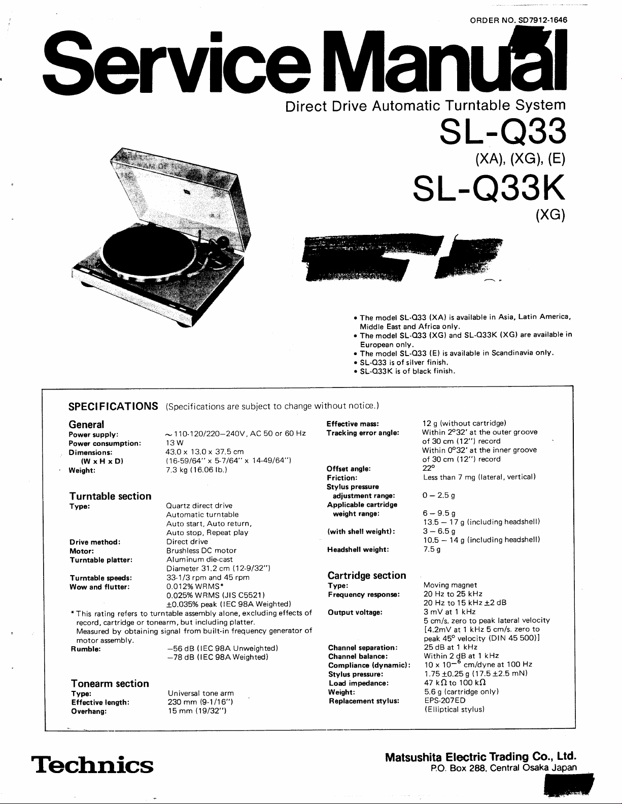
ServiceManu6l
Direct
Drive
Automatic
Turntable
sL-o33
(xA),(xG),(E)
SL-O33K
System
(XG)
SPECIFICATIONS
General
Power
supply:
Power
consumption:
Dimensions:
(WxHxDl
Weight:
and
platter:
flutter:
section
turntable
by obtaining
signal
Turntable
Type:
Drive method:
Motor:
Turntable
Turntable speeds:
Wow
*
This rating refers to
record, cartridge or tonearm,
Measured
motor assembly.
Rumble:
Tonearm section
Type:
Effective length:
Overhang:
(Specif
ications
-
110-12O/22O-240V.
13W
x 13.0 x 37.5 cm
43.0
(16-59/64"
(16.06
ks
7.3
Ouartz direct
Automatic
Auto start,
Auto stop.
Direct drive
Brushless
Aluminum
Diameter
rpm
33-1/3
O.O12o/o WRMS*
WRMS
O.O25o/o
+0.035%
assembly alone, excluding
but including
from
-56
dB
-78
dB
Universal
mm
230
15 mm
n9/32"1
are subject
x
5-7
/64"
lb.)
drive
turntable
return,
Auto
play
Repeat
motor
DC
die-cast
cm
31.2
peak
(lEC
(lEC
tone arm
(9-1/16")
112-9/32"1
45
and
(JlS
(lEC
platter.
built-in frequency
Unweishted)
9BA
Weishted)
98A
AC 50
14'49/64"1
x
rpm
C5521)
98A
to change
or
60
Weighted)
effects of
generator
Hz
of
o
The model SL-O33
Middle
.
The model SL-O33
European
.
The model SL-O33
o
SL-O33
o
SL-Q33K
without
notice.)
Effective mass:
Tracking
Offset
Friction:
Stylus
Applicable
(with
Headshell weight:
error angle:
angle:
pressure
adjustment
rango:
weight
shell
Cartridge
Tvpe:
Frequency
voltage:
Output
Channel separation:
Channel
Compliance
Stylus
Weight:
balance:
pressure:
Load
impedance:
Replacement stylus:
East
is
range:
cartridge
weight):
section
responss:
(dynamic):
(XA)
Africa only.
and
(XG)
only.
of
is of
(E)
finish.
silver
finish.
black
(without
g
12
Within 2032'
30 cm
of
within oo32'at
of 30
220
Less
than
O-2.5g
6-9.5g
-
13.5
3-6.59
-
10.5
7.5
s
Moving magnet
Hz
20
20HztolSkHz+2dB
3mVatlkHz
5 cm/s.
[q.ZmV
peak
25 dB at
Within
x 10-6
10
.75
1
kQ
47
g
5.6
EPS-2O7ED
(Elliptical
is available
SL-O33K
and
is available
cartridge)
the outer
at
record
fi2")
the inner
(12")
mg
7
(including
g
17
(including
g
14
kHz
25
zero
to
kHz 5
1
at
1 kHz
2 dB at
cm/dyne at
s
100
to
stylus)
record
(lateral,
peak
1
(17.5
kO
only)
cm
to
45o velocity
+O.25
(cartridge
in Asia,
(XG)
in
Scandinavia
groove
groove
vertical)
headshell)
headshell)
lateral
zero
cm/s.
(DlN
45 500)I
kHz
100
+2.5
mN)
Latin America,
are available
only.
velocity
to
Hz
in
Technics
Matsushita
P.O.
Electric
Trading
Box 288, Central
Co.,
Osaka
Ltd.
JaPan
Page 2
TECHNISCHE
DATEN
(Anderungen
der
technischen
Daten
vorbehalten.)
Allgemeine Daten
Stromversorgung:
Leistungsaufnahme: 13
Abmessungen
Gewicht:
(B
x H x
Wechselstrom
T) : 43,O
7,3 kg
Plattenspieler
Tvp:
Antrieb:
Motor:
Plattenteller:
Plattentel
G leichlaufschwankungen
*
Rumpel-Geriiusch-
Rumpel-Fremd-
Ier-Drehzahlen :
Diese Nennleistung
aussch I ieBl
aber
eingebauten
spannungsabstand:
spannungsabstand
ich E i nf
einschlieBlich
Frequenzgenerator
[issen vo
O uarz-D irekta
Automatischer
P
Startautomatik
RLickf
Stoppautomatik
Wied'erhol-Betrieb
D irektantrieb
Kollektorloser
A
Durchmesser
33-1/3 und 45
:
O,O12 WRMS*
o,o250/o
+0,035%
bezieht
n
Plattenteller.
-56
-78
110-12O/22O-24OV.50/60
W
'l
x
3,0 x
37,5 cm
ntr ieb
lattenspieler
ilhrautomatik
luminium-SpritzguB
sich auf
Scha
Gemessen anhand
des Motorbauteils.
dB
dB
G
31
U/min
WRMS
Spitze
das Laufwerk-Bauteil
I lplatte,
To
(lEC
98A
(lEC
98A
irekta ntrieb-
Ouarz-D
leichstrommotor
,2cm
(JtS
C5521)
(lEC
9BA bewertet)
nab
neh
mer oder
von
unbewertet)
bewertet)
Hz
allein,
narm,
To
Signalen
Tonarm
Typ:
Effektive
Uberhang:
Effektive
Spurfehlwinkel:
Kriipfungswinkel:
Lagerreibung:
Auf lagekraft-E
Zuldssiger
Gewichtbereich:
(mit
Zusatzgewicht)
Tonarmkopf-Gewicht:
Tonabnehmer
Tvp:
Frequenzgang:
Ausgangsspannung:
vom
Kanaltrennung:
Kanalabweichung:
Nachgiebigkeit
Auflagekraft:
lmpedanz:
Gewicht:
Ersatznadel:
Linge:
Masse:
lbereich :
i nstel
Tonabnehmer-
(dynam
n
iversal-Tonarm
U
230 mm
15
mm
g
12
f nn6rhalb 2032'
einer 30 cm-Platte
Inn6rhalb
einer 30 cm-Platte
22o
Weniger
0-2,59
6-9.59
1 3.5-1 7
10,5 - 14
7,5
S
'Mag
netischer
20 Hz bis 25 kHz
2O Hz
3 mV bei 1 kHz
cm/s.
5
14,2
(DtN
450
25
dB bei 1 kHz
lnnerhalb 2 dB
:
ischl
10 x 10-6
1,75+O,25
47 kQ
g
5,6
EPS-207 ED
(ohne
Tonabnehmer)
0032' bei
mg
als 7
(einschlieBlich
g
(einschlieBlich
g
Tonabnehmer
15
kHz
bis
Null-zu-Spitze,
mV
bis 1 kHz 5 cm/s. Nullzu-Spitze
45500)l
bei 1
cm/dyn bei 100 Hz
('17,512,5
s
100 kO
bis
Tonarmkopf)
{ohne
(
Elliptische Nadel
Einlaufrille
bei der
Auslaufrille
der
(horizontal,
Tonarmkopf)
2 dB
A.
lateral
kHz
mN)
vertikal)
Tonarmkopf)
)
SPECIFICATIONS
G6n6ralit6s
Alimentation:
Consommation:
Dimensions(LxHxPl
Poids:
Platine
Type:
Systdme
Moteur:
Plateau
Vitesses
Pleurage
*
Ronflement:
Bras
Type:
Longueur
Porte-C-faux:
de lecture
d'entrainement: Entrainement
de lecture:
de rotation:
et scintillement:
Ce r6gime
excluant
lecture,
signal
du
les
mais
provenant
moteur.
nominal
effets
comprenant
du
se
du disque,
g6n6rateur
de lecture
effective:
rapporte
(Les
sp6cif
ications
Alternatif
13
43,0
7,3
Entrainement
automatique
Demarrage
Retour
Arret
Audition
Moteur
Aluminium
Diamdtre
33-1/3
O,O12o/o
O,O25o/o de valeur
+0,035%
-56
-78
Bras
230
'15
11O-12O/22O-24OV,50
W
x 13,0
x 37,5
kg
direct
automatique
automatique
automatique
r6p6t6e
direct
C.C.
sans
moul6
31.2
cm
45
et
t/p.m
WRMS*
de cr6te
d l'ensemble
de la
cellule
plateau.
le
dB
d
de
fr6quences
de
(lEC
B ( IEC
lecture
Mesu16
98A
98A
universel
mm
mm
sont
cm
quarz
d
balai
pression
sous
efficace
(lEC
98A Pond6r6)
du
pick-up
par
incorpor6
pond6r6)
Non
Pond6r6)
susceptibles
ou 60 Hz
platine
(JlS
Cb521)
tournedisque
ou du
l'obtention
bras de
l'ensemble
de
d'6tre modifi6es
Masse
r6elle:
Angle d'erreur
Angle de d6calage:
Frottement:
Plage
de rftllage
pression
du
pick-up
cellule
contrepoids
la cellulel
la
de
en fr6quence:
de sortie:
de
de lecture
d'appui:
pick-up
(dynamique):
Gamme
(avec
Poids
Cellule
Type:
R6ponse
Tension
seul,
d,un
Sdparation
Equilibrage
Elasticitd
Pression
de lecture:
lmpddahce
Poids:
Pointe
remplacement:
pr6avis.)
sans
piste:
de
de la
poids
de la
utilisable:
de
cellule:
de canal:
des canaux:
pointe
ta
de charge:
de
(sans
g
12
En
disque de 30
En
disque
220
Moins de 7 mg
0-2,5
6-9,5
13,5-1 7
3-6,5
10,5-1 4
7,5
Aimant
20
20 Hz
3 mV
lat6rale
14,2mV
450
25dBd
En
10 x
1
,75
47
5,6
EPS-2O7ED
(Forme
la cellule
decd
de
2032'au
decA de
0032'au
de 30 cm
s
9
lv
S
g
lv
S
g
mobile
Hz
d 25 kHz
d 15 kHz
kHz,
d 1
cr6te
de
d 1 kHz5cm/s.,z6rod vitesse
de
cr6te
1 kHz
decd
de 2
10-6
cm/dyne
+
gramme
0,25
kQ
to 100
grammes
elliptique)
pick-up)
sillon
cm
sillon int6rieur
(lat6ral
compris
compris
+2dB
5 cm/s.
45
[DtN
dB d 1 kHz
d 100
(17,5
kO
(cellule
seule)
ext6rieur d'un
vertical)
et
la coque
la
coque
z6ro
it
500]
)
Hz
+
2,5
d'un
porte-cellule)
porte-cellule)
vitesse
mN)
E
Page 3
I CONTENTS
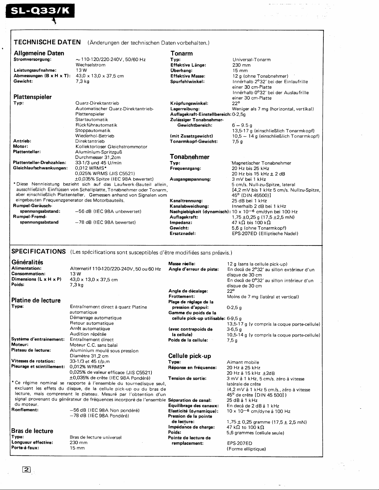
LOCATIONOFCONTROLS.
DISASSEMBLY
ADJUSTMENTS
REPLACEMENT
FLOW CHART
MN14OOPA
BLOCK
BLOCK
SCHEMATIC
LOCATION
I
PROCEDURE
.
PARTS
OF
DIAGRAM
DIAGRAM
DIARGRAM
AUTO
lC.
OF
LIST
START
OF
(EIECITiC
.
.
PATTS}
MOTION
CONTROLS
..3-4
5-6
6-9
. . .
.
. .12
13
15
15
-14
-16
-16
11
WAVEFORM
BOARD
TRANSISTOR
OF
TONE
OF
AND
AT
DRIVE
ARM
(Mechanical
LIST
EACH
AND
lC
. .
IC.
CONTROL
Parts)'''''
REFERENCE
PRf NTED
TERMINAL
TIMING
TONEARMDRIVECONTROLMECHANISM.
REPLACEMENTPARTS
EXPLODED
VOLTAGE
CIRCUIT
GUIDE
CHART
VIEW
-18
17
-18
17
18
. .
. .
19
. .
.
. . .
.
"
Photo
. .
.
.
'21-24
19
20
sensor
Hinge
spindle
Center
Turntable
Strobe
Strobe-illuminator/
Start/stop
Speed
Reoeat button
platter
dots
button
select buttons
I
trl
45-rpm
Balance weight
Stylus-pressure
Anti-skating
Turntable
Headshell/cartridge
Stand-by switch
Cueing
adaptor
ring
control knob
Arm clamp
mat
Tonearm
Locking nut
button
E
Page 4
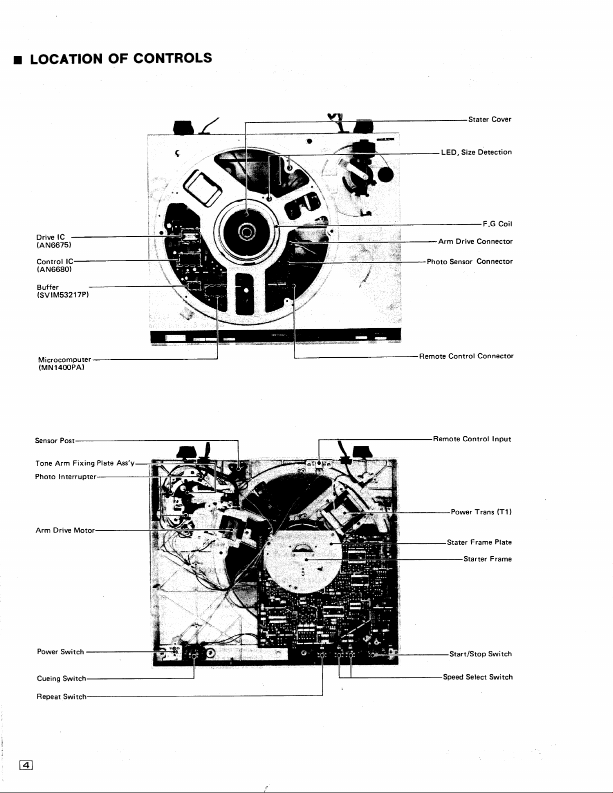
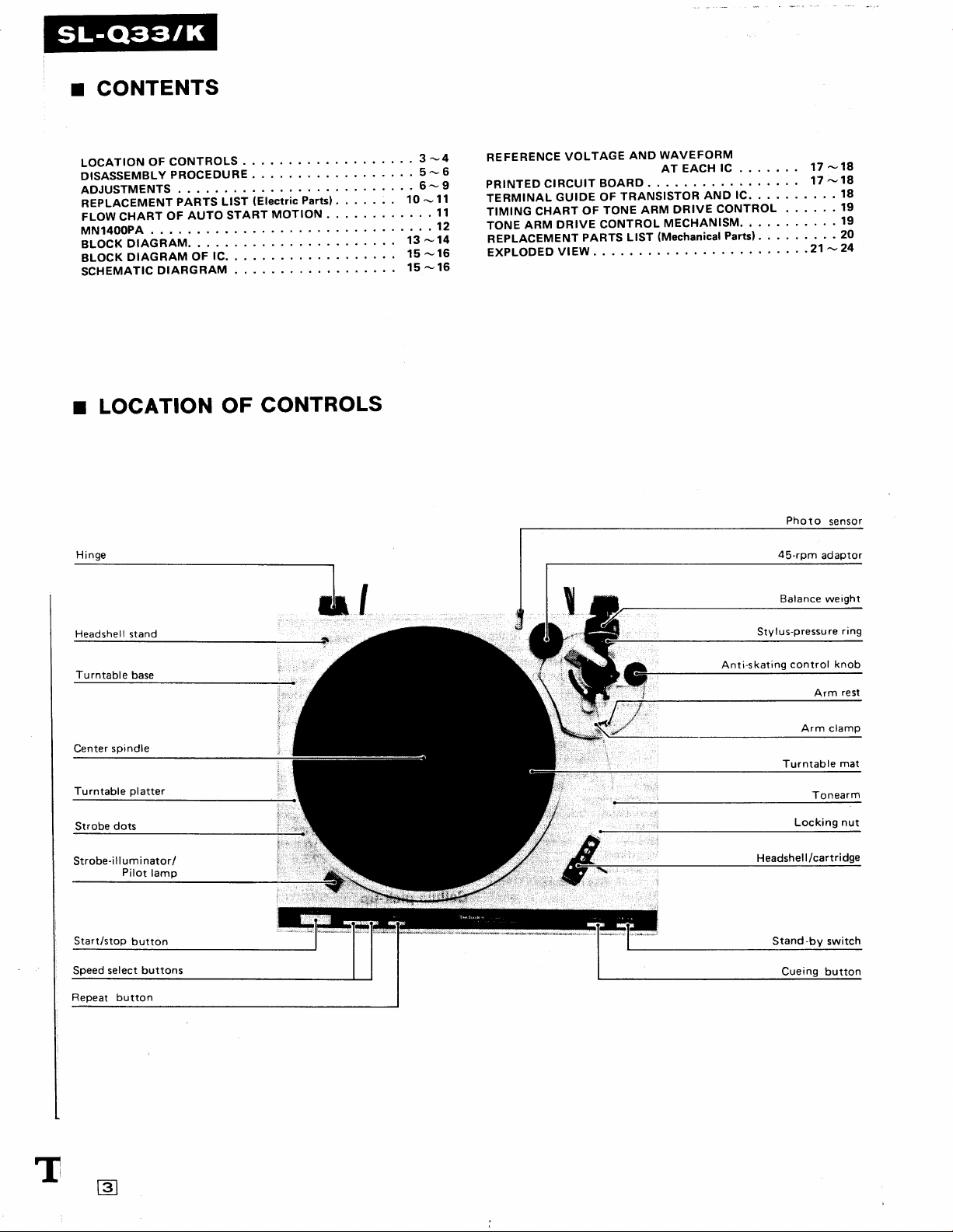
I LOCATION
CONTROLS
OF
Stater
Cover
lC
Drive
(AN6675)
lC
Control
(AN6680)
Buffer
(svrM53217P)
Microcomputer
(MNl4OOPA)
Post
Sensor
'---*1,r
LED, Size
Arm Drive Connector
Photo
Sensor
Remote Control
Remote
Control Input
Detection
Connector
Connector
Tone
Arm
Photo
Interrupter
Drive Motor
Arm
Power
Switch
Cueing Swi
Repeat
Switch
Fixing
Plate
Ass'Y
Trans
Switch
(T1)
Power
Start/Stop
Speed Select Switch
@
Page 5
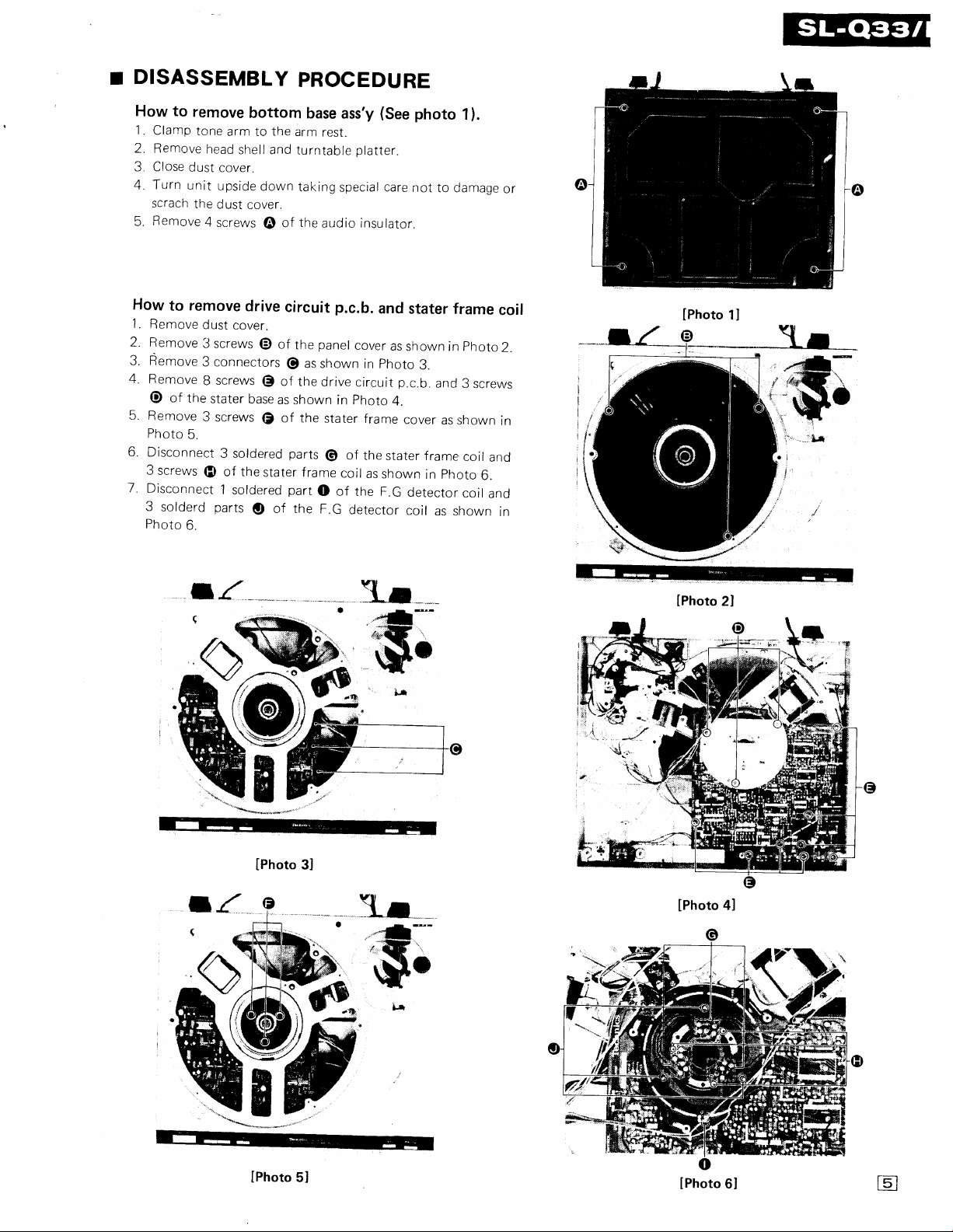
DISASSEMBLY
r
to
How
1
. Clamp
2.
3. Close
4. Turn
5.
remove
tone
Bemove
dust
unit
scrach
the
Remove
arm to
head
cover.
upside
dust
4
screws
bottom
shell and
cover.
PROCEDURE
base
ass'y
the
arm
resr.
down
of
@
turntable
taking
the
special
audio
platter.
insulator.
(See
care
photo
not
to damage
1).
or
How
1.
2. Remove
3.
4.
5.
6.
remove
to
Remove
Remove
Remove
of
the
@
Remove
Photo
5.
Disconnect
3
screws
Disconnect
3
solderd
Photo
6.
;{
drive
dust
cover.
3 screws
3 connectors
screws
8
stater
3
screws
3 soldered
(D
of the
1
parts
of
@
of
@
base
as
of the
€
stater frame
soldered
of the
o
circuit
panel
the
as shown
@
the
drive
shown in
stater
parts
@
part
o
F.G
p.c.b.
cover
in
circuit
photo
frame
of
the
coil
as
of
the
detector
and
stater
as
shown
photo
p.c.b.
4.
cover
stater
shown
F.G
detector
coir
frame
in
3.
and
as shown
frame
photo
in
as shown
photo
3
screws
coil
and
6.
coir
and
coil
2.
in
in
lPhoto
lPhoto
1l
2l
lPhoto
e
lPhoto
5l
3l
ar--
ffi
lPhoto
o
o
lPhoto
4l
6l
E
Page 6
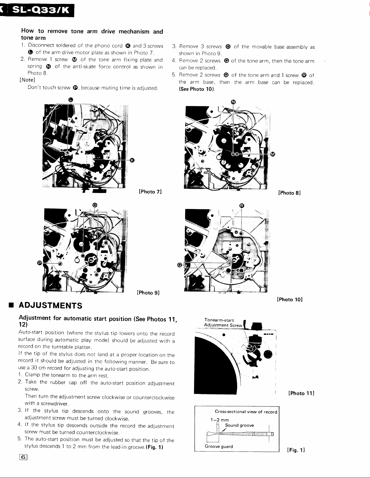
How
to
remove
tone
arm
1. Disconnect
(!
of the
arm drive
2. Remove
spring
Photo
INoteJ
Don't
l
0
B.
tolrch
tone
soldered
screw
@
of
the
anti-skate
screw
@,
arm drive
phono
of
the
plate
motor
of
the tone
force
because muting
mechanism
cord
as shown
fixing
arm
control
time
6
in
is
and
3
screws
Photo
plate
as
shown in
adjusteo.
lPhoto
7.
and
ano
7l
Remove
3.
shown in
4.
Bemove
ran hp ronl:nprl
Remove
the arm base,
{See
3 screws
Photo
2
2 screws
Photo
9.
screws
then
10)
of
the
O
of the
@
of the tone
@
the arm base
movable
tone arm,
arm
base
assembly
then the
and 1
screw @ of
can
be replaced.
lPhoto
tone
8l
as
arm
I
ADJUSTMENTS
Adjustment
for
automatic
12l.
Auto-start
surface
record
lf
the
record
use
.1.
Clamp
2.
rake
SCTEW.
Then
with
3.
lf
adjustment
4. lf
screw
5.
The
stylus
position
during
automatic
on
the
turntable
tip
of
the
stylus
it
should
be
a
30 cm
record
the
tonearm
the
rubber
turn
the
adjustment
a
screwdriver.
the
stylus
tip
screw
the
stylus
tip
must
be turned
auto-start position
descends
1 to
adjusted
for
t6l
start
(where
must
descends
the
stylus
play
mode)
platter.
does
not
in thc following
adjusting
to
cap
descends
counterclockwise.
2 mm from
the
arm rest.
off
screw
be
turned
must
the
outside
the auto-start
onto
be
position
tip lowers
should
land
at a
auto-start
clockwise
the
clockwise.
the
adjusted
the
lead-in
lPhoto 9l
photos
(See
onto
be adiusted
proper
location
manner.
position.
position
or
sound
record
so
groove.(Fig.
adjustment
counterclockwise
grooves,
the
adiustment
that
the
the
Be
tip
record
with
on
the
sure
the
of
the
1)
11,
a
to
Tonearm-start
Adjustment
1-2
Groove
Screw
Cross-sectional
mm
guard
view
s
of record
lPhoto
lPhoto
lFig.
101
1
1
1I
l
Page 7

Adjustment
INoteJ
Adjust
respect
o
Automatic
1. Fix
2. Remove
.
the
to 1 7cm
the tone
position
screwdriver,
. .Turn
.
.Turn
Automatic
1.
Shift
2. Turn
screw
.
.Turn
retu
.
.Turn
return
for
automatic
position
and
return
adjustment
arm on
the rubber
adjusting
the screw
returns
return
during
the
after
return
tfre
tone
the
17
with
a screwdriver.
the
rns
d uring
the
af ter the
return
according
30cm records.
of
the rest.
cap
of the
screw,
counterclockwise
performance.
screw
crockwise
the
end
adjustment
arm
inside.
cm record
screw
counterclockwise
performance.
screw
clockwise
end
of
position
to the following
30 cm
disc
photo
(See
30 cm
and
then
performance.
of
of 17
(See
automatic
performance.
when
cm disc
photo
return
when
12)
record
turn
the
13)
the
procedure
automatic return
the
screw
with
when
the
tone
tonc arm does riot
position
when
tone
the
arm
adl ust i ng
IOne
does
with
arm
arm
not
a
n1
Juslme
disc record)
121
lPhoto
Auto
return
adjustment
(17
point
cm disc
record)
Adjustment
This
unit
is
ritating
or lifted
adlusted
stylus
the
Photo
The
before
following
being
o
o
o
Remember
SCTEW.
lf recorded
was
turning
the
In
the
screw
lNotel
As
adlustment
f
reely
Also
arm
noise
up from
by
tip and
"UP"
position
14).
height
shipment
manner
used.
To
begin
protecter.
Push
the
turntable
The
top
arm lift
case
down,
lowered
the ad
distance
irritating
record
surface,
clockwise.
the
adjusting
(See
photo
be sure
lift
when
e
of
muting
fitted
caused
the
the record
of the
with,
stand-by
does not
of
the adjustment
to depress
sound cannot
onto
justment
between
while
that
the latter
timing
with
a muting
at
the moment
the record
height
(V
arm lift
from
the factory.
when
protect
switch
move.
turn
the
the
the record
screw
the
noise
is
decrease
screw has
depressing
16)
hexagonal
the
is released.
(height
feature
the
surface.
of
the
arm
lift,
surface
while
the
by depressing
),
was
adjusted
perfom
adjustment
the
ro
screw
adjustment
arm lift
be reproduced
surface,
counterclockwise,
stylus
generated
the
hexagonal
a
the
is
tip
of
rhe
O
is
hexagonal.
screw.
when
try
tip
and
the record
when
distance
arm
lift
head
of
arm
lift)
which
is used
stylus
is
Muting
a clearance
top
of
the rone
the
cueing
to a range
the
adlustment
needed
the
position
the
by
head
or the
retracts
for
stylus
while
turning
at once
to
adlust
and
stylus
turning
be sure
screw
correctlv
to
cur off ir-
brougnt
(
surface.
down
timing r;an
between
arm rs
button.
of
b - 1o nrm
the
cartridqe
with
the
r
so
)
holdinq
the
adjustment
after
the
the
timing
thus
increasing
is lowered
the
adjustment
to make
not
will
into
In
stylus
that
stylus
onto
move
on
be
the
at
(See
tne
the
the
by
the
the
-10
5
ry\*
2
lPhoto
cm
lPhoto
lPhoto
131
141
Arm-tift
adjustmen
151
,."
t
E
Page 8

\
JUSTIERUNGEN
Justierung der automatischen
(Abb.
11,121
Die Auto-Start-Position
rnatischen
sollte
Plattenteller
\\/enn
Platte
Verwenden
stel lung
'1.
Befestigen
der
Nehmen
2.
tion-J
Drehen
benzieher i m
Wenn
3.
abgesenkt
Uhrzeigersinn.
4.
Wenn
wird, drehen
Uhrzeigersinn.
5. Die
die Nadelspitze 1
entfernt aufsetzt.
Betrieb auf
justiert
die
landet,
Tonarmablage.
Auto-Start-Position
werden, wenn
liegt.
auf
Nadelspitze nicht auf
sollte die
unbedingt
Sie
der Auto-Start-Position.
den
Sie
die
Sie
ustiersch
die
raube
dann die
Sie
Uh
Nadelspitze auf den
wird, drehen
Nadelspitze auBerhalb
die
(wo
die Schallplattenoberfl6che
Position
Tonarm mit
Gummikappe
ab.
Justierschraube
rzeiger-oder Gegenuh
die
Sie
bis 2
(Abb.
1)
Stan-Position
Nadelspitze
die
eine
Schallplatte
richtigen
der
wie folgt
cm-Platte
30
eine
Arretierklammer
der
von der
rzeigersinn.
Wiedergabeteil
Justierschraube
die
Sie
der
Justierschrabue entgegen
muB
so eingestellt
mm
der duBersten
von
beim
aufsetzt)
auf
auf der
Stelle
justiert
Auto-Start-Posi'
mit
Platte abgesenkt
ftlr
einem
der Platte
weden,
werden.
die
Schrau-
Tonrille
auto-
dem
Ein-
auf
im
dem
da8
Adjustierung der automatischen R0ckkehrpositaon
Anmerkung:
den
dem
mit
der GroBe
(Siehe
der
Uhrzeiger-
einer
wenn
nicht
Adjustieren
folgenden Anweisungen
von 17 cm und
dei Position in Ubereinstimmung
Sie
unter Berlicksichtigung
30 cm
Schallplatten.
r\uto-Riickfilhreinstellung ftir
1. Befestigen
Abb.12)
2. Entfernen
automatischen
und
Schraubenzieher.
"
Drehen
sinn,
Schal
*
Drehen
der
zur Ausgangsposition zuriickkehrt.
Sie den
Sie
drehen
die Einstellschraube entgegen
Sie
wenn der
lplatte vorzeitig
Sie
Tonarm nach
Tonarm
die Gummikappe der Einstellschraube
Ri.ickkehrposition
Sie diese
Tonarm
die Einstellschraube im
Beedigung
auf dem Tonarmrest.
Einstellschraube mit einem
wdhrend des
riickkehrt.
zu
des Abspielvorgangs
30 cm
Schallplatten
fiir
30 cm Schallplatten,
Abspielens
Uhrzeigersinn,
Justierung der
(Abb.
14)
Dieses Gerdt ist
stattet,
oder
Die
hohe
Tonarmlifthohe ist
Schallplattenoberfldche,
hobenen Position
Die Tonarmlifthohe
einen Bereich von
Wenn
ung
vor.
o
.
o
Damit sich
To
Falls die Tonwiedergabe
der
kiirzen
schraube
stand zwischen
vergroBert wird.
Falls
Gerdusche
durch
Anmerkung:
Da die
Tonarmliftfi.ihrung
r0ckt
drehen
Vergewissen Sie
liftfiihrung
welche die stcirenden Gerdusche
Abheben
Diimpfungszeit
justiert
fur den
erforderlich ist,
Setzen
Schalten
Plattenteller nicht drehen
der
Die Justierschraube
die Justierschraube,
frihrung
I iftf
narm
Nadel
Sie
beim
Drehen der Justierschraube
Justierschraube
gehalten
ldBt.
Ddmpfungszeit
mit
einer Ddmpfungsvorrichtung ausge-
Nadelspitze
der
kann durch Regulieren der
weden,
Sie
Sie
niedergedr0ckt
iihru
auf
die
entgegen
Absenken
gehiirt
zurUckkehrt,
indem
Abstand
der
wenn
(V)
ist.
vor
ist
-10
5
zu
verwendenden
nehmen
zuerst
den Ein/Aus-Schalter
die
ng u nbed
die Schallplattenoberfliiche
Ddmpfungszeit
der
sich,
Nadelschutz auf.
den
hat einen
wdhrenddem
Schraube
i ngt neidergedrUckt
dem
Nadelspitze
oder
werden:
einen Sechskantkopf
wbhrend
werden, damit
daB der Sechskantkopf
wenn
(Tonarmlifthiihe)
beim
ausscheidet.
Tonarmlift-
Lifttaste
die
der
der
mm
eingestellt worden.(Abb. 19.)
Tonabnehmer
Sie
kann.
halten.
leicht drehen
sofort
nicht
durch
Uhrzeigersinn,
Abheben
Verringern Sie
des
diese
gedrtickt
zwischen Nadelspitze
Tonarm
Auslieferung
diese
Sechskantkopf.Drehen
der Plattenoberfliiche
und
im Uhrzeigersinn.
Justierens
sich die Schraube
losgelassen
in
im Werk
eine Justier-
folgende
auf
(r.),
aus
Sie
nach dem Absenken
Drehen
der Nadel
damit sich
die Tonarmlift-
la8t,
werden.
beginnt:
der
wodurch
den Abstand
hat, muB die
unbedingt
in die
wird.
Absenken
wird. Die
und
ange-
der
auf
Weise
Sie
muB die
Ver'
Justier-
der Ab-
stiirende
ged-
leicht
Tonarm-
Auto-Rtickf0hreinstellung
1.
Schieben Sie
2. Drehen
Riickfiireinstellung
Schraubenzieher.
'
Drehen
sinn,
Schallplatte
*
Drehen Sie
Tonarm
der
zu r
Ausgangsposition zuriickkehrt.
den Tonarm
die
Sie
Sie
wenn
Einstellschrabue der
fiir 17 cm
die Einstellschraube entgegen dem
der
Tonarm wiihrend
vorzeitig
die
nach
zur0ckkehrt.
Einstellschraube
Beedigung des Abspielvorgangs
E
ftir 1
7 cm Schallplatten
innen.
nach
Shcallplatten
des Abspielens
im Uhrzeigersinn,
(Siehe
Abb.
automatischen
mit
Uhrzieger-
131
einem
einer
wenn
nicht
Page 9

r REGLAGES
Rdglage
matique
La
pointe
le mode d'audition
avec
I'extr6mit6
Si
l'endroit
fagon
de
30 cm
d6marrage.
Bloquer
1.
Retirer
2.
d
Puis,
sens des
3. Si
sillons
dans
4.
Si
du dique, la
inverse
La
5.
de
descende
(Fig.
R6glage
pour
(Fig.
11,121
position
un disque
e
l'extr6mit6
d'autod6marrage
de lecture
appropri6 du disque,
suivante.
posit
avec un
I'extr6mit6
le
sens des
des
position
fagon
1l
s'abaisse sur la surface
plac6
de la
S'assurer tout d'abord d'utiliser un disque
pour
la mise
le
bras
le
capuchon en caoutchouc de la vis de r6glage
ionnement
tournevis, tourner la
aiguilles d'une montre
de la
du
disque, la
de la
vis
aiguilles d'une montre.
d'auto-d6marrage
d
ce
i 1 ou 2 mm
de la
matique
Note:
R6gler
ction des
R6glage
de
1.
2.
position
la
diques
de
du retranchement
30 cm.
Fixer
le
bras
acoustique
graphie
D6poser
de
de
.
o
12).
le
capuchon
position
la
30
et
cm
tourner la vis
Tourner la vis
pendant
revient
Tourner la vis
pas
revient
aprds la f in de la lecture.
de retranchement
position
une
automatique)
plateau
le
suf
pointe
au
lecture
de
d'autod6marrage.
pointe
vis de r6glage
aiguilles d'une montre.
pointe
de 169lage devra
que
l'extr6mit6 de
partir
i
position
en respectant
17 et
30 cm.
de d6marrage
(lorsque
devra
de l'6lectrophone.
de lecture ne descends
devra
elle
point
de
l'accoudoir
sur
vis
dans le
ou
lecture
de
lecture
de
Otre tourn6e
devra 6tre mise
la
du sillon
retranchement
de
proc6d6
le
automatique du
sur son appui.
de
caoutchouc de la vis
automatique du disque
l'aide d'un
d
gauche quand
d
la
lecture.
quand
droite
d
le
auto-
l'extr6mit6 de la
disque
169l6e de la
du bras.
sens
dans le
au
de lecture
d6part.
pendant
point
pas
d'atuo-
inverse.
les
sur
tournde
sens
point
du
6tre mise au
6tre
position
la
de r6glage dans le
descends
devra Otre
descends en dehors
pointe
du
auto-
suivant,
en
fon-
disque
(Voir
tournevis.
le
bras acoustique
bras
photo-
la
de r6glage
acoustique ne
point
au
Mise
(hauteur
cieux
(Figs.
141
Cet appareil est 6quip6 d'un dispositif
qui
est utilis6
moment
i
de la
La
o!
surface
synchronisation d'accord silencieux
point par
l'extr6mit6
que
alors
"ttp"
(Y
),
de la synchronisation d'accord silen-
du
souleveur
pour
couper
pointe
la
de
du disque.
la hauteur du
pointe
de la
le
sommet
en
appuyant sur
du bras de lecture est i la
souleveur
du bras).
d'accord
les
bruits irritants caus6s
lecture
s'abaisse sur ou
peut
du bras, l'intervalle
de lecture
la
touche commutatrice
et
la
surface
silencieux
se souldve
etre mise
entre
du
disquS
position
pose
de
au
au
et de relevage.
hauteur
La
de
5 - 10 mm
Ex6cuter
r6glage
o
Tour
lecture
o
Couper
que
.
Le
du
souleveur
avant d'Otre exp6di6e
la mise
au
est ndcessaire
d'abord,
avec
prot6ger
capot
son
l'interrupteur
platine
la
dessus de
ne
la
vis
point
pour
puisse
de r6glage est
Tout en maintenant le
tourner la
pas
Ne
tourne
vis
de r6glage.
oublier d'abaisser
la vis
de r6glage.
Si le son enregistr6 ne
que
apr6s
disque: Essayer
vis de r6glage dans le
et en
pointe
Dans le
de
lecture est
distance
iguil les
a
pointe
la
de leeture s'est abaiss6e sur la surface du
d'ajuster
augmentant
ainsi
de lecture et la
cas oir
bruit irritant se
un
abaiss6e
en tournant la
d'une montre.
sens inverse
du
bras a 6t6
de la manidre
la
cellule
r6gl6e
l'usine.
de
suivante
de lecture
sur une
utilis6e.
I'extr6mitd de la
protecteur.
(r),
d'alimentation
de fagon
tourner.
hexagonal.
souleveur
le
souleveur
peur
Otre reprciduit imm6diatement
l'accord
distance
la
du disque.
surface
de bras vers le bas,
du
bras
silencieux
des
entre
produit
en tournant
aiguilles
d'une
l'extr6mit6 de la
lorsque
sur la surface du disque: Diminuer
vis
r6glage dans le
de
plage
(Fig.
191
lorsqu'un
pointe
A ce
lorsqu'on
montre
pointe
la
sens
de
la
la
des
Nota:
Comme
s'assurer
la vis de r6glage
d'effectuer
l'6l6vateur
V6rifier
dans
aussi
l'6l6vateur
du bras,
que
la t€te
du bras
possOde
mise
la
la
sinon
hexagonale
quand
une t€te
point
au
vis
ne bougera
se
ce dernier est
hexagonale,
en
tout
abaissant
pas
librement.
retire correctement
lib6r6.
R6glage
de
1.
2. Tourner la vis
du retranchement
17
cm.
Porter
le
bras
graphie.
automatique
o
o
13)
Tourner
revient
Tourner
revient
la vis
pendant
la vis
pas
acoustique vers
de 169lage
du
disque de
aprds
de la
17
gauche
i
la lecture.
i droite
la f
in de la lecture.
automatique du
l'int6rieur.
position
cm, d I'aide d'un
quand
quand
(Voir
de retranchement
le bras
le
bras acoustique ne
disque
photo-
la
tournevis.
acoustique
E
Page 10

i
I
i
REPLACEMENT PARTS LIST ( Electric
r
Notcs3 1.
No.
Ref.
Part
numbers
Please
use this
2. A indicates
Part
are indicated on
number for
that
only
No. Part Name & Descriotion
most
parts
parts
mechanical
orders.
specified by the manufacture be used
parts.
rc
rcl
tc2
rcl0l
rc20r
rc40r
tc402
TRANSISTORS
Q10r
Q102,201,202
0203
Q40l - 406, 409
0407,408,410
@0r,902
0903,904,
907 - 909
Q905,906,
910 - 914
PHOTO
TNTERRUPTERS
PC501
PC502,503
DIODES
DI
Dr0l
D201,202
0203,204,404
D205,401-403,
901-906
D907^€09
CRYSTAL
x201
FOWER
TRANI MER
T1
s:wtTcHEs
s201
,202,
-403
401
s501
.502
s601
s70i
s80'
FUSE
FI
F2
RESISTORS
R l0'l
R
102
R
103
R
104
R
105
R 106
R
107
R
108
R1@
Rll0
R20l
svruPc14312
svrFs7805c
AN6675
AN6680
MNI4OOPA
SVIM53217P
25864r
25D636
2SC1&l8.7
25D636
25864r
25D638
2S8643
2SD636
oN1r28
128SK
oNr
BBA2OZ
SVDSl
20A90
SVDEBRS5OSS
SVDSR I OsC
MAl62A
SVDGL.52O
svou306r 15 Crystal
SLT54D1 E
EVQP5R04K
SF DS D2MSC
A
ES86237
SFDSHSWO665B
A
SFDSHXWl33I2
XBA2CO2T
A
XBA2CO6 TRO
A
ERO25FJl03
E8XlANJ2R7
ERO25F,W2
ERD25TJ473
ERD2SFJT03
ERD25FJT5(I
ERD25FJ56:I
ERD25TJ473
ERD25TJT53
ERDzsFJ222
ERO25FJ31
Integrated
I
Integrated Circuit, Drive
lntegrated
Integrated Circuit,
Integrated Circuit,
Transistor
Transistor
Transistor
Transistor
Transistor
Transjstor
Transistor
Transistor
Photo
Photo. I nterrupter
Rectif ier
Diode, Ge
Diode, Si
Light Emitting Diode
Diode,
Light Emitring Diode
Power Transformer
Switch,
Switch,
Switch,
Switch,
Switch,
Fuse,
IA
Fuse,
Carbon,
Metal Film,
Carbon, 4.7kQ, 114W, i
Carbon.
Carbon. lOkO, 1/4W, + 5ol
Carbon, 15O, 1l4W, !. sot
Carbon,
Carbon,
Carbon,
ntegrated
Interrupter
Si
200
600
Carbon,
Carbon,
Circuit, Regulator
Circuft
Regu lator
,
Circuit,
Drive
Micro Computer
BuJfer
Start/Stop,
Limit
fower
Muting
Power
Repeat
Source
mA
mA
l0k0,
2.7n, lW, t 5ol
47kQ,
5.6kO,
47kQ,
15kO, 1/4W,
2.2kQ,
3300,
and Cueing
'l/4W,
t
t-
114W,
1/4W, !
1/4W, ! sot
!
114W, i 59
*.50/
1/4W,
5ol.
5%
5ol
5ot
5o/,
Parts)
for
R202
R203
R204
R205
R206
R207
R208
R209
R2r0
R21
l
R212
R2l3
R214
R215
R2'16
R217
R21
8
R2r9
R22Q
R221
R222
R223
R224
R40r
R402
R403,404
R405,406
R407-409
R4'10,41 1
R412
R41
3
R41
4
R415-417
R4l8
R4r9
R420,421
R422
R423-427
R428
R429
R430
R901, 902
R903,904
R905,906
R907,908
R909, 9 r
0
R91 1
R9r2,9r3
R9r4
R915,916
R917
R9r8,919
R920
R921
R922
R923
R924
R925
R926
R927
F928
R929
R930
R93r,932'
safety.
ERD6TJ153
ERD25FJ4ru
ERD6TJ154
ERD25TJ223
ERO25FJl02
EBD25FJ332
EBD25FJ221
ERD25FJ471
ERD26FJ272
ERD25TJ124
ERD25TJ183
ERD25TJ56|I
ERD25TJ22'I
ERD6TJI54
ERD26TJ223
ERD25FJl08
ERD25FJl2I
ERD25TJ223
ERD25FJl03
ERD25FJ221
ERD25FJ561
ERD25FJ391
ERD6TJ223
ERD25FJ181
ERD26TJ223
FRD25FJ102,
ERD?6FJ222
ERDzSFJ4ZI
ERDzsTJ104
ERD25TJ473
ERD25FJ102
ERD2SFJ4ZI
ERD25TJ223,
ERD25TJ183
ERD25TJI23.
ERD25FJl02
ERD25FJ15{I
ERD25FJ472
ERD25FJ682
ERD25FJl03
ERD25TJ473
ERD25FJl02
ERD25FJ471
ERD2SFJ3SI
ERDziFt2122
ERD25FJ33:I,
ERGlANJlsO
ERD2SFJT02
ERGlANJISO
ERD2SFJTO:I
ERGIAilJT5{'
ERD2SFJT02
ERD25FJ331
ERD25FJlOI
ERD25FJ471
ERD25TJ47'I
ERD25FJ3!I2
ERD25TJ47'I
ERD25FJl02
ERD25FJlO:I
ERD25FJ4I2
ERD25FJl03
ERD26FJII72
ERD25FJ103
H1
ECQMl
ECKDl
ECEBlHS47l
ECEAlCS22l
53KZ
H223ZF
Carbon,
Carbon,
Carbon,
Carbon,
Carbon,
Carbon,
Carbon,
Carbon,
Carbon,
Carbon,
Carbon
Carbori,
Carbon.
Carbon.
Carboq,
Carbon,
Carbon,
Carbon,
Carbon,
Carbon,
Carbon.
Carbon,
Carbon,
Carbon,
Carbon,
Carbon,
Carbon.
Carbon,
Carbon,
Carbon,
Carbon,
Carbon,
Carbon,
Carbon,
Metal Oxide,
Carbon,
Metal Oxide,
Carbon,
Metal,Oxide,
Carbon,
Carbon,
Carbon,
Carbon,
Carbon,
Carbon,
Carbon,
Carbon,
Carbon,
Carbon,
Carbon,
Carbon,
Carbon,
Polyester, 0.0159F,
Ceramic,
Ef ectrolytic,
Electrolytic,
2.7kO,
120kO,
18kO,
22kO,
10kO,
120o,
22k4,
1OkO,
22OQ,
560fl,
3900,
22kO,
180O,
22kQ,
1kO,
2,2k4,
4.7kO.
100kO,
47kO,
1kO,
4.7kQ,
22kQ,
18kO,
1kO,
15O.
4.7k{1,
6.8kO,
lOkO,
47kQ,
'l
kO,
47OQ,
3.3kO,
2-2kQ,
3.3kO,
150.
1kO,
l5(l.
1kO,
150,
I kO,
3300,
10OO,
47OQ,
470kO,
3.3kO,
470kO,
lkO,
10kO,
4.7kO.
10kO.
4.7kO.
10kO.
O.A2ZPF,
7OyF,
22OPF,
*.
1/4W,
1/4W, .r.
a
114W,
1/4W, .r
+.
1/4W,
1/4W, i
*.
114W,
114W, i.
*.
1lAW,
r.
1/4W,
*.
1/4W,
+.
1/4W,
1/4W,.r.
*.
1/4W,
a,
114W,
i
114W,
.r
114W,
r
1/4W,
a.
1/4W,
114W,
r
r.
114W,
*,
114W,
i
114W,
*.
114W,
a.
114W,
+,
1/4W,
*.
114w,
1/4W,
+
L
1/4W,
i,
1/4W,
r
114W,
i.
1/4W,
*.
114W,
r
1/4W,
i
1/4W,
*
114W,
i
1/4W,
1/4W, r
L
114W,
!
1/4W,
*,
1/4W,
r 5%
1/4W,
i
114W,
r.
114W,
a
1/4W,
j,
114W,
r
lW,
*,
114W,
.r,
1W,
*.
114W,
tw,
114W,
114W,
1l4v,l,
1l4V,l,
114W,
114W,
'v4w,
1l4u,t,
114W,
114W,
1/4W,
114W,
50V,
50V,
50V
16V
*.
i,
i
A.
r.
a
a,
r
r.
r.
a
.r
r
50/o
5%
5%
5%
5%
5%
5%
@
Page 11

No.
Ref.
c6
C7
101-103
C
C104-107
08
c1
r10
cl09,
11
cl
c112
c201
c202
c203
c204,205
c206
c207
c208
c2@
c210
c211
c212
c213
c214
c215
Part
No.
Ecenraszzr
ECQM.IHl04KZ
ECEAICS33o
Hl04KZ
ECOMl
ECEAlESlOI
ECQMl HlO4KZ
ECQM'IH562KZ
ECEA25Z4R7
ECEAlCS330
ECEA50Zl
ECEAlES4TO
ECEA50Zl
ECQMl H473KZ
ECEAlAS22l
ECEA50Zl
ECCDI H rS'rK
H33OK
ECCDl
ECCD1 H471
ECEAlES4TO
ECQMl
ECaMI H473KZ
ECEASOZ3R3
K
H224KZ
Part Name
Electrolytic,
Polyester,
Electrolytic,
Polyester,
Electrolytic, 100pF,
Polyester,
Polyester,
Electrolytic,
Ef
ectrolytic,
Electrolytic,
Eelctrolytic,
Electrolytic,
Polyester,
Eelctrolytic,
Electrolytic,
Ceramic, 150pF,
Ceramic,
Ceramic, 47OpF,
Electrolytic,
Polyester;
Pofyester,
Electrolvtic.
& Descriotion
22OyF,
0.1ttF,
33yF, 16V
0.1pF,
0.1yF,
0.0056pF,
4.7pF,
33ltF
,
lttF,
471tF,
lpF,
0.O47yF, 50V, Ll0%
22OpF,
lpF,
33pF, 50V, tl}o6
47yF,
O.22tlF,
O.O47lrF,
3.3lrF
. sOV
50V
i.109
50V,
r.loq
50V,
25V
Ll07
50V,
tloo/l
50V,
25V
l6V
50V
25V
50V
50V
50V
50V, !1Oo/.
50V, LIOTc
25V
i.10%
50V,
50V, ilO%
No.
Ref.
c2r6
c217
c401
c402
c403
c404
caos
c406
c407
c408-412
c901, s02
c903
c904
c905
c906
c907
c908
c909
c910
r
c9r
c9r2^€r4
Part
No.
ECEAlASlOl
ECKDlHlO4ZFZ
ECEAlCS330
ECKD 1 H |O4ZFZ
HIOl
ECCDl
ECKD1E473ZF
ECKDl H223ZF
ECKDl E473ZF
ECQMI Hl04KZ
ECKDl E102K
ECOMl
ECKDlH 1O4ZFZ
ECEAlCS22l
ECKDIH.IO4ZFZ
ECSFl6EIOZ
ECQMl H 1
ECKDIHl02KB
ECQMIHl02KZ
ECEAlHSlOO
ECKDI HI02KB
ECKDIHIO4ZFZ
K
H103KZ
02KZ
Part
Name & Description
Electrolytic,
Ceramic, O.'lyF, 5OV,
Electrolytic, 33pF,
Ceramic,
Ceramic, 100pF,
Ceramic,
Ceramic,
Ceramic, O.O474F, 25v
Polyester,
Ceramic, 0.0014F,
Polyester,
Ceramic, O.1ltF
Electrolytic, 22OyF,
Ceramic, O.11tF, sOV,
Tantalum, lOyF, l6V,
Polyester,
Ceramic,
Polyester,
Electrolytic, lOyF,
Ceramic,
Ceramic,
IOO4F
o.iyf
O.OA7pF, 25v,
0.0221tF,
O.lpF, 50V,
0.01pF, 50V,
0.00,|pF,
0.001f
0.0O llF, 50V
0.0O1pF,
O.lttF,
'l
0V
,
'l
6V
50V,
,
50V,
50V,
25V,
sOV,
l6V
50V,
F,
sOV,
50V
sOV
50V
l!8n
1!8x
llool
198*
+RQx
198*
t10ol.
198*
t1O%
:98*
198n
tlOoA
198*
i1
198*
:gg*
FLOW
r
CHART OF
AUTO
switch
S/S
Turntable
Arm turns
START
push
rotate
motion
(Cueing
MOTION
(cueing
works)
works)
S/S switch
"ON"
E
Return
motion
peat
switch
E
Page 12

I
MN14OOPA
PIN
NAMES
Pin
No.
AND
Symbol
FUNCTIONS
Name
OF MN14OO
Function
2
3
4
5
6
7
I
I
10
l1
12
13
14
1
Vss
Co9
Co8
Ground
Repeat
Start/Stop
Co7
Co6
Co5
AI3
At2
AIl
AIO
BI3
BI2
BIl
Start/Stop
Cueing
Limit
Limit
Cueing
Start/Stop
Start detection
End
End
BIO Rest
and repeat
switch
switch
detection
detection
Reduction
LED lamp
Start-Stop control
provided
No
For
When
this
Both in
Input
Input
The terminal
"H"
When
turned
Like
terminal
"L"
out
of
to earthing
for
switch
Signal.
to this
set.
start-stop
the cueing lever
terminal
terminal
terminal
instructions.
are shorted.
indicate
for
for
"H"
cueing
start-stop
to check if
level
during rotation.
pulse
the
to
BI2 terminal, end detection
level
for
"H"
and
end defection
and
the
this
terminal.
when the arm
the rest.
potentiona
repeat
"H"
switch is
level
at
(2
(Normally
indication.
level
turned
cueing
motionsl.
and repeat.
the turntable
arm return
of LP record
motion follows.
of EP
is on the rest and
at
up.
0V)
"H"
level
start.
to
direction, AIl and
up
is in
rotation.
give,
is
record
is
made
"H"
level if the arm is
at
ON.
the level
by BI2
is
15
16
17
18
19
20
2l
22
23
24
Eo0
Eol
Eo2 Motor
Eo3
TST
FS
SNSO
SNSl
Do0
Dol
25 Do2
26
27
28
Do3
voo
osc
Motor drive
Motor
drive
drive
Test
Reset input
Sensor
Sensor
LED drive
LED drive
LED drive
Power
input
Oscillator
input
terminal
terminal
terminal
Instruction is
rotation,
Not
used
Normally
computer.
this
Turn
This is
input
The
The
output terminal
Not
used
Vp9 voltage is
The combination
generate
oscillation
given
reverse rotation,
for
this set.
used at
terminal
connected to
from
for
this set
applied.
clock
signal,
circuit
to
the arm and the
low
"L"
level
to test
"L"
to
level, then
ground
photo
the
of a resistor and
which
for
sensor is
generate
to
(Standard
and the required
contains
speed, high,
driven
the discrete
the
micro computer
use.
given
as a
the inflared
+$y1
a capacitor
clock is obtained
LSl.
motor
speed)
unit
pulse.
ray,
as the
(Forward
micro
of
LED
terminal to
reset.
is
by the
Page 13

LOCK
DIAGRAM
Position
detection
coil
tcl0l
(AN6675)
R
R
102
103
-1
I
I
I
Drive
coil
nror
Q101,
r02
(AN6680)
rc20r
l----.
I
I
I
L-
AC
Line
50/6OHz
Power
s60l
switch
one
arm
"'*r'r't ,-f
t
Q405'406
switch
Limit
s502
R429
PC501
position
Start
detectton
position
End
detection
t
I
r@-q
F-sr
Atc
Atl
At2
Br0
Bn
t_
Bt2
j*
Bl3
I
SNS2
SNSI
Q9l0-912
g-l
VDO
Pulse
amp
R418
tc402
I
J
E
E
Page 14

Q101,
102
(AN6680)
tc201
r--
-
x20t
DH11l-l
R223
c209
CzrO
lD
pon
ll
g-l
f*'
iNST
r)l
t\
Pulse
Q9l0-912
vDo
oor
Doz
amp
R4r8
Photo
sensor
N
T
J
rF;A;E;l;;-I
I
detectionl
+
I
Qe
r3,
914
Storobo-illuminator
t,
^taR2l8
eoo
(
I
po.tl
lE
-l
I
CO8.
I
Lt*
C09
.,,t
.
E3 E4
1C402
l-
(Svtu532r7P)
--l
Arm motor
drive circuit
-906
Q901
Arm drive
motor
t)
.//
-Y'n,)
/
--oa
Muting Switch
S701
/
i
Page 15

SCHEMATIC
t
1
DIAGRAM
POWER
'ol
As6ot
SVDSIRB
r-------l
(Tnis
Aor
schematic
A2OZ
diagram
3
may
modified
be
(
* 12V line)
at
any
time
with the
development
4.5
of
new
rcror
technr
AN6675
SVIpPC
t4312
SVIFSTSOSC
D404
SVDSR-IO5C
o404
250636
"Jr
Hl
;
EI;
D2O3.2O4
SVDSR-IO5C
(L
o
o
g
z
=
o
!t
9
(
line)
4o3
o4or-
MAtso zsa'641-'
(L
o
F
o
F
cr
ur
o.roz,.o8.4ro
o/ro9
2SD63F
* l2V
E5
(
*
line)
12V
REflOTE Cff{TROL
r lERlft{rt
tNR
E
Page 16

':
)pment
of
...
new
technologr.l
.-,,-
,',,tt:.,
--
OlOl(G.,
oA90
OIOA
MA
t50
OtOl
25864l
oro2
2SD636
0203
2SCt328
|03.4!O
,41
O.lO9
(
*
l2V line)
r\\
PHoro sEl'$m
\
0907-
909
SVDGL-52O
PCSO|
oN I t28
PC5O2
5O3
t
oNil28SK
ARII
MOIER
PCfll
REST
PCs02
LP
END
PC503
SIARI
AND
END
DRIYE
SENSOR
RECORO
SENSOR
POS/I'ON
EP
SENS(}R
RECORD
TOIE
PUT
CfiTROL
IERU'Ifl-
E
Page 17

o--+
O--g
\
/'-. i\
31,
s
Ii
.l.
ll
+l
tl
\l I
'l
I
i
#
i"+
a
Page 18

H
fl:
m
#"tP'
V
@
Page 19

EXPLODED
r
VIEW
......Q)
,-]
$
o---{
-/Al 'o
ffioJ
UU\D
*-=4
O1
Gi
a€a--
)
Tgl
'/'/
ff"P,
d
34
rt--3{-,
@
Page 20

\
9
n*
^!
.ffi-,
ffi%^t'ff.
T'
w+'7ol'v'^'
w Lff.w
.).sjrffiffi|Ftr-,#
r_]-t
wiii
r__,_6h ,,1 , rjj
{rl(_
rm
bi"
trg
I
Ib
""'*f.5
@
F'N-'
HV-'
A-r
L,
@
ffil
-f
.@
9---fuL-@
o------t
.fr.tei
'o-
t\
\'
ry
i
79127,8OO
@
O.O.
 Loading...