

Page 1
ORDER NO.PSG1502003CE
Compact Disc Player
Model No. SL-C700E
Product Colour:
(S) ...... Silver Type
© Panasonic Corporation 2015. All rights reserved.
Unauthorized copying and distribution is a violation
of law.
Page 2

TABLE OF CONTENTS
1 Safety Precautions -----------------------------------------------3
1.1. General guidelines -----------------------------------------3
2Warning--------------------------------------------------------------4
2.1. Prevention of Electrostatic Discharge (ESD)
to Electrostatic Sensitive (ES) Devices---------------4
2.2. Service caution based on legal restrictions----------5
2.3. Precaution of Laser Diode -------------------------------6
2.4. Handling Precaution for CD DRIVE
UINT(Optical Pickup)--------------------------------------7
3 Specifications ------------------------------------------------------8
4 Location of Controls and Components--------------------9
5 Troubleshooting Guide---------------------------------------- 11
5.1. Check the problem is reproduced-------------------- 11
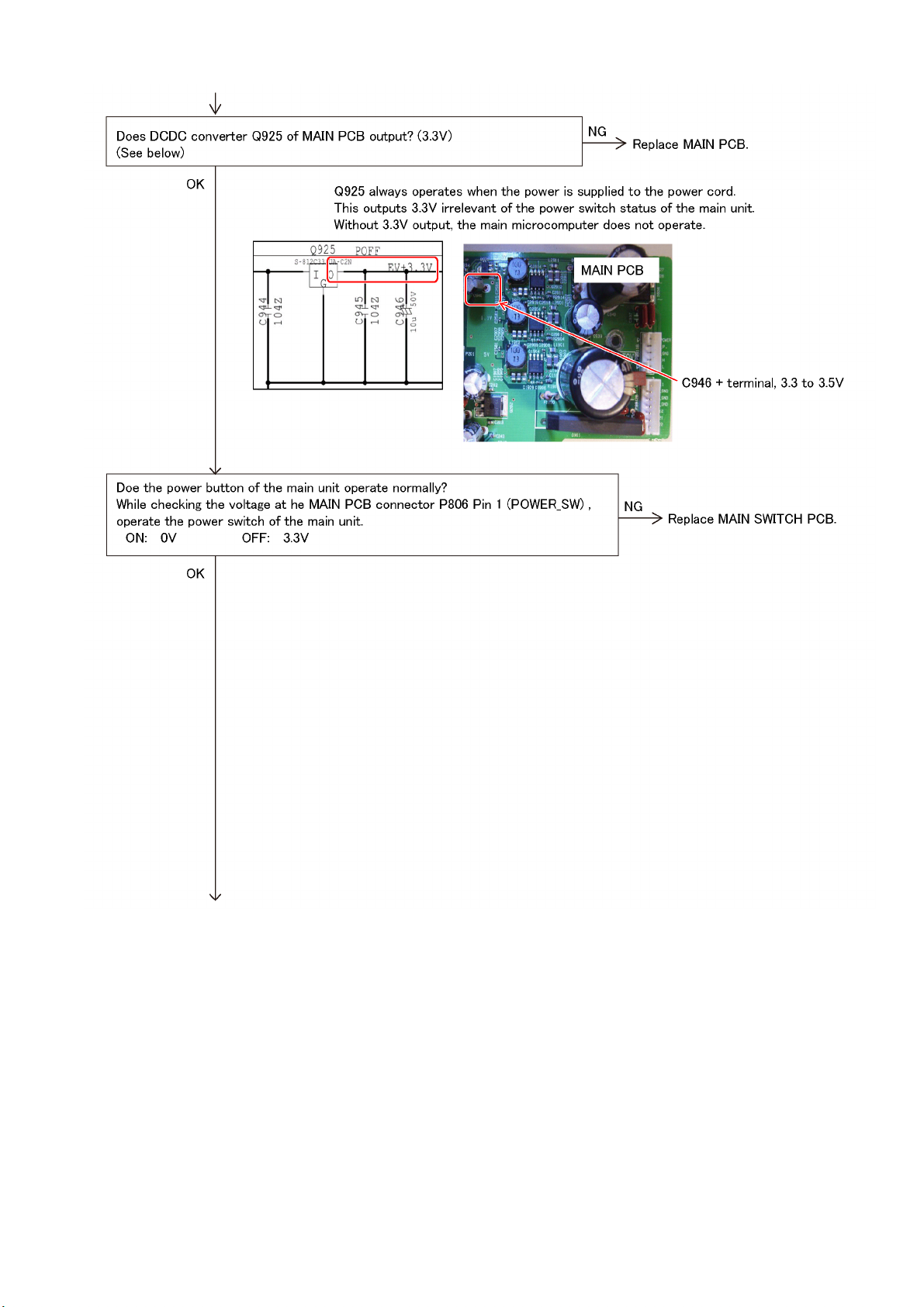
5.2. No power --------------------------------------------------- 12
5.3. LED does not illuminate --------------------------------17
5.4. No buzzer -------------------------------------------------- 17
5.5. Remote control does not operate --------------------17
5.6. No Display ------------------------------------------------- 18
5.7. No CD operation------------------------------------------ 19
5.8. Connector pin configuration --------------------------- 20
5.9. Blocks related to each function ----------------------- 21
6 Disassembly and Assembly Instructions --------------- 22
6.1. PCB layout drawing-------------------------------------- 23
6.2. Removing the disc when the disc cannot be
removed using the opening-closing button -------- 25
6.3. Disassembly flow chart ---------------------------------26
6.4. SET LEG UNIT ------------------------------------------- 27
6.5. TOP AL PANEL------------------------------------------- 27
6.6. TOP CABINET BLOCK --------------------------------- 27
6.7. SIDE PANEL (R), SIDE PANEL (L), TOP
PANEL ------------------------------------------------------ 27
6.8. FRONT PANEL UNIT ----------------------------------- 28
6.9. TOUCH SENSOR PCB, PICT LIGHTING
WINDOW--------------------------------------------------- 28
6.10. DISPLAY PCB, OLED ASSY-------------------------- 28
6.11. IR PCB, MAIN SWITCH PCB ------------------------- 29
6.12. FRONT PANEL ASSY ---------------------------------- 29
6.13. BELT LOADING ------------------------------------------ 29
6.14. CD MECHA BLOCK, DOOR -------------------------- 29
6.15. SPRING, CD LOADING UNIT ------------------------ 30
6.16. INSULATOR, CD DRIVE UNIT ----------------------- 30
6.17. REAR PANEL ---------------------------------------------30
6.18. MAIN PCB ------------------------------------------------- 31
6.19. SOFTWARE IN 1 PCB, SOFTWARE IN 2
PCB---------------------------------------------------------- 31
6.20. CD MECHA DRIVE PCB ------------------------------- 31
6.21. PS PCB -----------------------------------------------------32
6.22. AC INLET PCB ------------------------------------------- 32
7 Dimensions ------------------------------------------------------- 33
8 Block Diagram --------------------------------------------------- 34
9 Wiring Connection Diagram --------------------------------- 35
PAG E PAG E
2
Page 3
1 Safety Precautions
1.1. General guidelines
1. When servicing, observe the original lead dress. If a short circuit is found, replace all parts which have been overheated or
damaged by the short circuit.
2. After servicing, see to it that all the protective devices such as insulation barriers, insulation papers shields are properly
installed.
3. After servicing, make the following leakage current checks to prevent the customer from being exposed to shock hazards.
1.1.1. Leakage current cold check
1. Unplug the AC cord and connect a jumper between the
two prongs on the plug.
2. Measure the resistance value, with an ohmmeter,
between the jumpered AC plug and each exposed
metallic cabinet part on the equipment such as
screwheads, connectors, control shafts, etc. When the
exposed metallic part has a return path to the chassis, the
reading should be between 1M and 5.2M.
When the exposed metal does not have a return path to
the chassis, the reading must be .
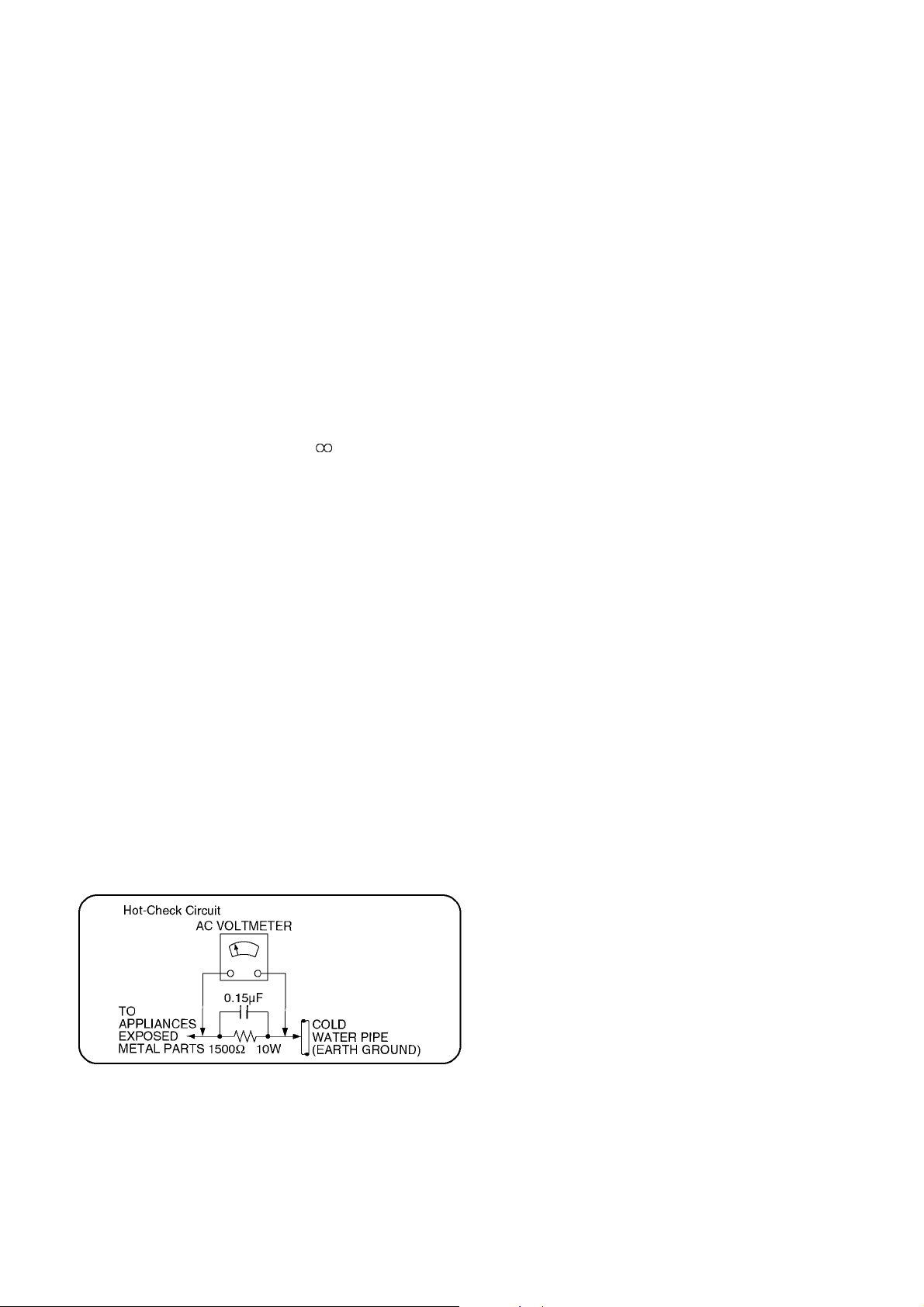
1.1.2. Leakage current hot check (See Figure 1.)
1. Plug the AC cord directly into the AC outlet. Do not use
an isolation transformer for this check.
2. Connect a 1.5k, 10 watts resistor, in parallel with a
0.15F capacitors, between each exposed metallic part
on the set and a good earth ground such as a water pipe,
as shown in Figure 1.
3. Use an AC voltmeter, with 1000 ohms/volt or more
sensitivity, to measure the potential across the resistor.
4. Check each exposed metallic part, and measure the
voltage at each point.
5. Reverse the AC plug in the AC outlet and repeat each of
the above measurements.
6. The potential at any point should not exceed 0.75 volts
RMS. A leakage current tester (Simpson Model 229 or
equivalent) may be used to make the hot checks, leakage
current must not exceed 1/2 milliampere. In case a
measurement is outside of the limits specified, there is a
possibility of a shock hazard, and the equipment should
be repaired and rechecked before it is returned to the
customer.
Figure 1
3
Page 4

2Warning
2.1. Prevention of Electrostatic Discharge (ESD) to Electrostatic Sensitive (ES) Devices
Some semiconductor (solid state) devices can be damaged easily by static electricity. Such components commonly are called
Electrostatic Sensitive (ES) Devices. Examples of typical ES devices are integrated circuits and some field-effect transistor-sand
semiconductor "chip" components. The following techniques should be used to help reduce the incidence of component damage
caused by electrostatic discharge (ESD).
1. Immediately before handling any semiconductor component or semiconductor-equipped assembly, drain off any ESD on your
body by touching a known earth ground. Alternatively, obtain and wear a commercially available discharging ESD wrist strap,
which should be removed for potential shock reasons prior to applying power to the unit under test.
2. After removing an electrical assembly equipped with ES devices, place the assembly on a conductive surface such as
aluminum foil, to prevent electrostatic charge buildup or exposure of the assembly.
3. Use only a grounded-tip soldering iron to solder or unsolder ES devices.
4. Use only an anti-static solder removal device. Some solder removal devices not classified as "anti-static (ESD protected)" can
generate electrical charge sufficient to damage ES devices.
5. Do not use freon-propelled chemicals. These can generate electrical charges sufficient to damage ES devices.
6. Do not remove a replacement ES device from its protective package until immediately before you are ready to install it. (Most
replacement ES devices are packaged with leads electrically shorted together by conductive foam, aluminum foil or
comparable conductive material).
7. Immediately before removing the protective material from the leads of a replacement ES device, touch the protective material
to the chassis or circuit assembly into which the device will be installed.
Caution
Be sure no power is applied to the chassis or circuit, and observe all other safety precautions.
8. Minimize bodily motions when handling unpackaged replacement ES devices. (Otherwise harmless motion such as the
brushing together of your clothes fabric or the lifting of your foot from a carpeted floor can generate static electricity sufficient
to damage an ES device).
4
Page 5

2.2. Service caution based on legal restrictions
2.2.1. General description about Lead Free Solder (PbF)
The lead free solder has been used in the mounting process of all electrical components on the printed circuit boards used for this
equipment in considering the globally environmental conservation.
The normal solder is the alloy of tin (Sn) and lead (Pb). On the other hand, the lead free solder is the alloy mainly consists of tin
(Sn), silver (Ag) and Copper (Cu), and the melting point of the lead free solder is higher approx.30 degrees C (86°F) more than that
of the normal solder.
Definition of PCB Lead Free Solder being used
The letter of "PbF" is printed either foil side or components side on the PCB using the lead free solder.
(See right figure)
Service caution for repair work using Lead Free Solder (PbF)
• The lead free solder has to be used when repairing the equipment for which the lead free solder is used.
(Definition: The letter of "PbF" is printed on the PCB using the lead free solder.)
• To put lead free solder, it should be well molten and mixed with the original lead free solder.
• Remove the remaining lead free solder on the PCB cleanly for soldering of the new IC.
• Since the melting point of the lead free solder is higher than that of the normal lead solder, it takes the longer time to melt the
lead free solder.
• Use the soldering iron (more than 70W) equipped with the temperature control after setting the temperature at 350±30 degrees
C (662±86°F).
Recommended Lead Free Solder (Service Parts Route.)
• The following 3 types of lead free solder are available through the service parts route.
SVKZ000001-----------(0.3mm 100g Reel)
SVKZ000002-----------(0.6mm 100g Reel)
SVKZ000003-----------(1.0mm 100g Reel)
Note:
* Ingredient: Tin (Sn) 96.5%, Silver (Ag) 3.0%, Copper (Cu) 0.5%. (Flex cored)
5
Page 6
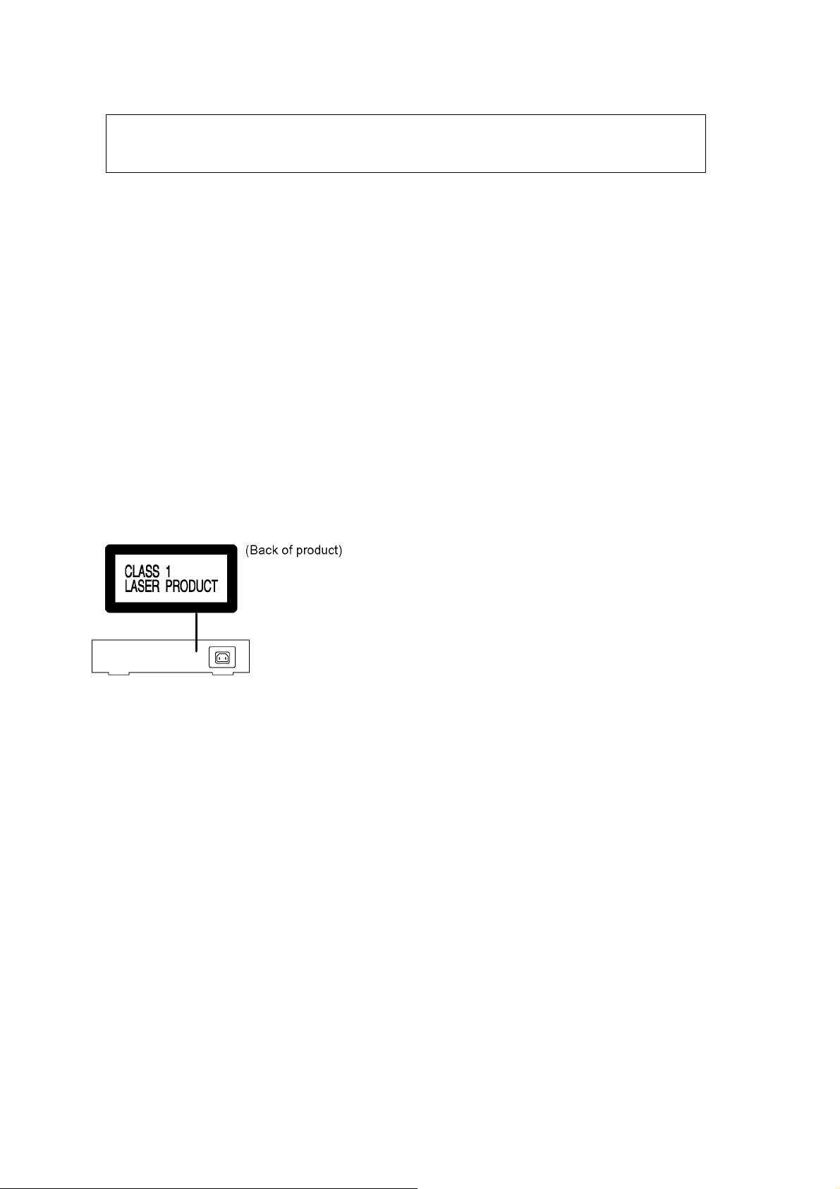
2.3. Precaution of Laser Diode
CAUTION!
THIS PRODUCT UTILIZES A LASER.
USE OF CONTROLS OR ADJUSTMENTS OR PERFORMANCE OF PROCEDURES OTHER THAN THOSE
SPECIFIED HEREIN MAY RESULT IN HAZARDOUS RADIATION EXPOSURE.
Caution:
This product utilizes a laser diode with the unit turned "on", invisible laser radiation is emitted from the pickup lens.
Wavelength: 790 nm (CD)
Maximum output radiation power from pickup: 100 μW/VDE
Laser radiation from the pickup unit is safety level, but be sure the followings:
1. Do not disassemble the pickup unit, since radiation from exposed laser diode is dangerous.
2. Do not adjust the variable resistor on the pickup unit. It was already adjusted.
3. Do not look at the focus lens using optical instruments.
4. Recommend not to look at pickup lens for a long time.
ACHTUNG:
Dieses Produkt enthält eine Laserdiode. Im eingeschalteten Zustand wird unsichtbare Laserstrahlung von der
Lasereinheitadgestrahit.
Wellenlänge : 790nm (CD)
Maximale Strahlungsleistung der Lasereinheit :100 μW/VDE
Die Strahlung an der Lasereinheit ist ungefährlich, wenn folgende Punkte beachtet werden:
1. Die Lasereinheit nicht zerlegen, da die Strahlung an der freigelegten Laserdiode gefährlich ist.
2. Den werkseitig justierten Einstellregler der Lasereinhit nicht verstellen.
3. Nicht mit optischen Instrumenten in die Fokussierlinse blicken.
4. Nicht über längere Zeit in die Fokussierlinse blicken.
6
Page 7
2.4. Handling Precaution for CD DRIVE UINT(Optical Pickup)
The laser diode in the CD DRIVE UINT(Optical Pickup) may break down due to static electricity of clothes or human body. Special
care must be taken avoid caution to electrostatic breakdown when servicing and handling the laser diode in the Traverse Unit.
2.4.1. Cautions to Be Taken in Handling the CD DRIVE UINT(Optical Pickup)
The laser diode in the CD DRIVE UINT(Optical Pickup) may be damaged due to electrostatic discharge generating from clothes or
human body.
Special care must be taken avoid caution to electrostatic discharge damage when servicing the laser diode.
1. Do not give a considerable shock to the CD DRIVE UINT(Optical Pickup) as it has an extremely high-precise structure.
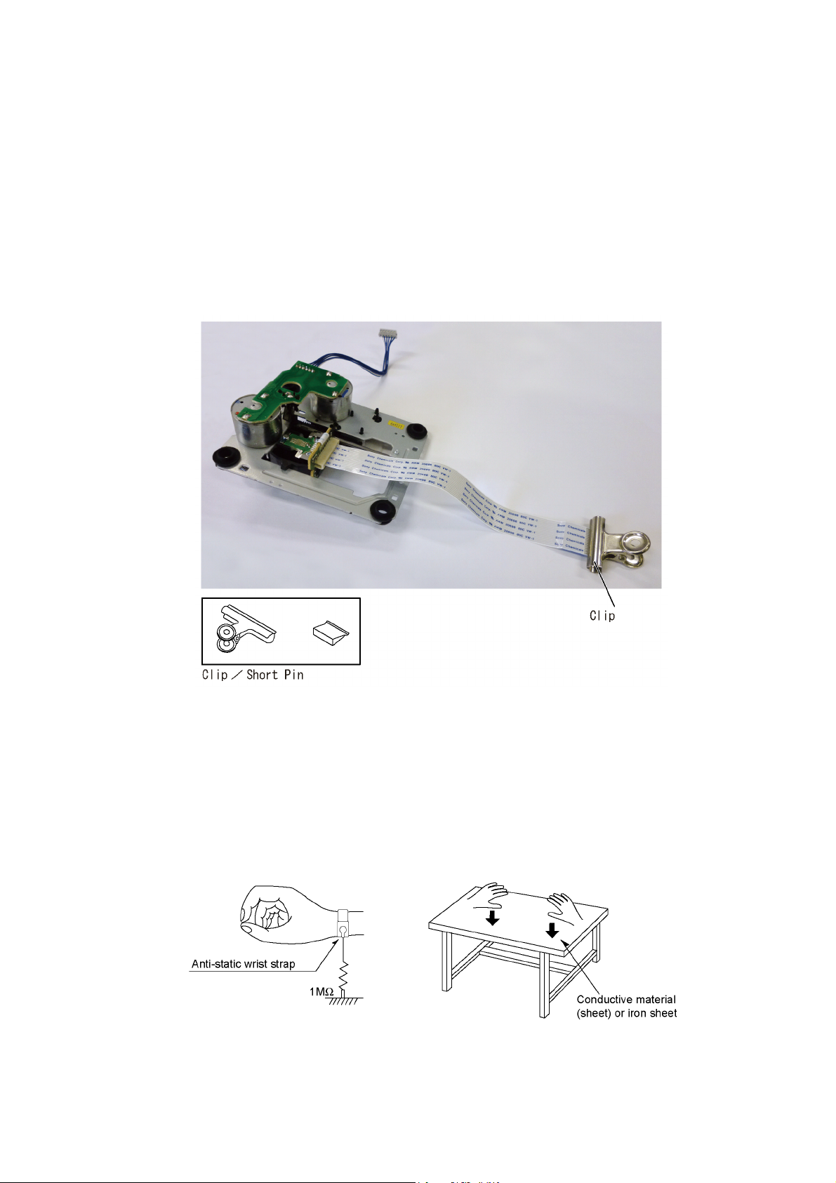
2. To prevent the laser diode from the electrostatic discharge damage, the flexible cable of the CD DRIVE UINT(Optical Pickup)
removed should be short-circuited with a short pin or a clip.
3. The flexible cable may be cut off if an excessive force is applied to it. Use caution when handling the flexible cable.
4. The antistatic FFC is connected to the new CD DRIVE UINT(Optical Pickup). After replacing the CD DRIVE UINT(Optical
Pickup) and connecting the flexible cable, cut off the antistatic FFC.
2.4.2. Grounding for electrostatic breakdown prevention
Some devices such as the CD player use the optical pickup (laser diode) and the optical pickup will be damaged by static electricity
in the working environment. Proceed servicing works under the working environment where grounding works is completed.
2.4.2.1. Worktable grounding
1. Put a conductive material (sheet) or iron sheet on the area where the CD DRIVE UINT(Optical Pickup) is placed, and ground
the sheet.
2.4.2.2. Human body grounding
1. Use the anti-static wrist strap to discharge the static electricity form your body.
7
Page 8
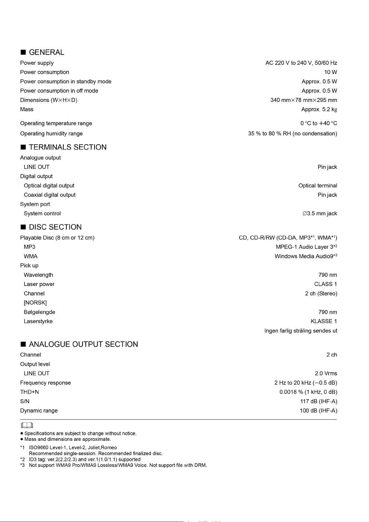
3 Specifications
8
Page 9
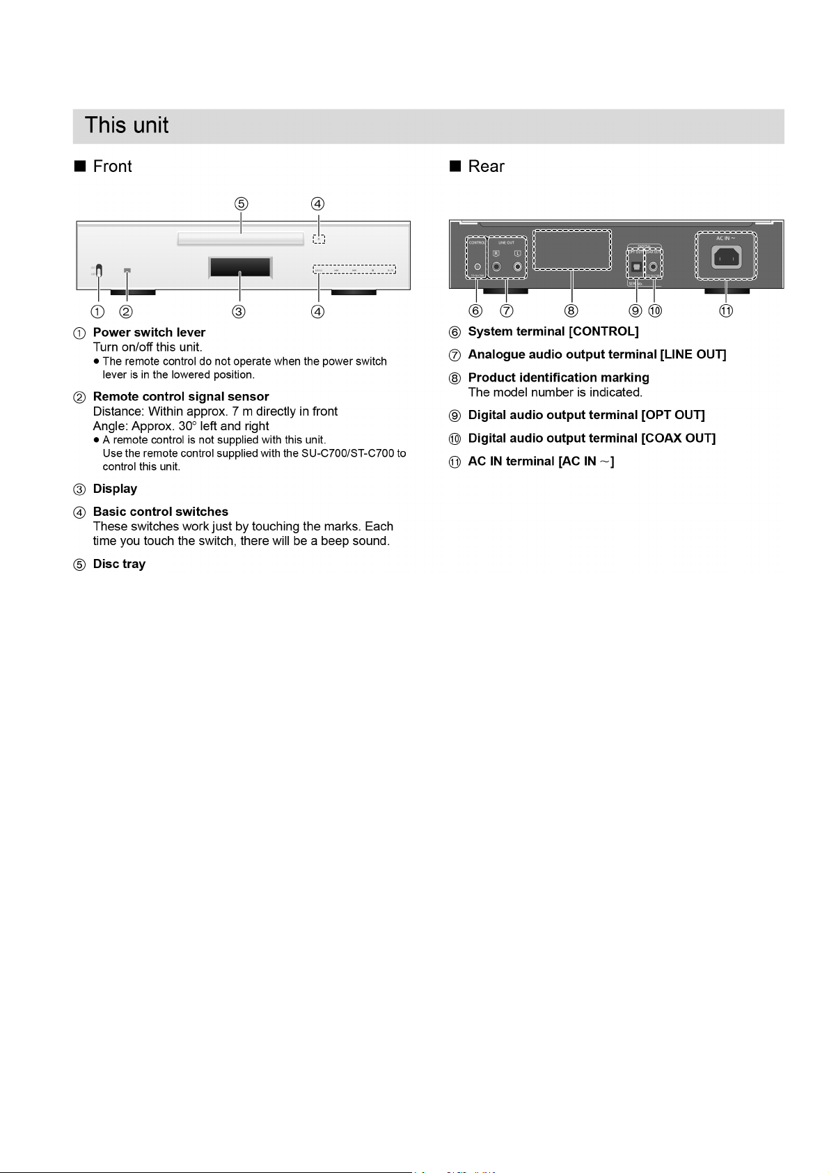
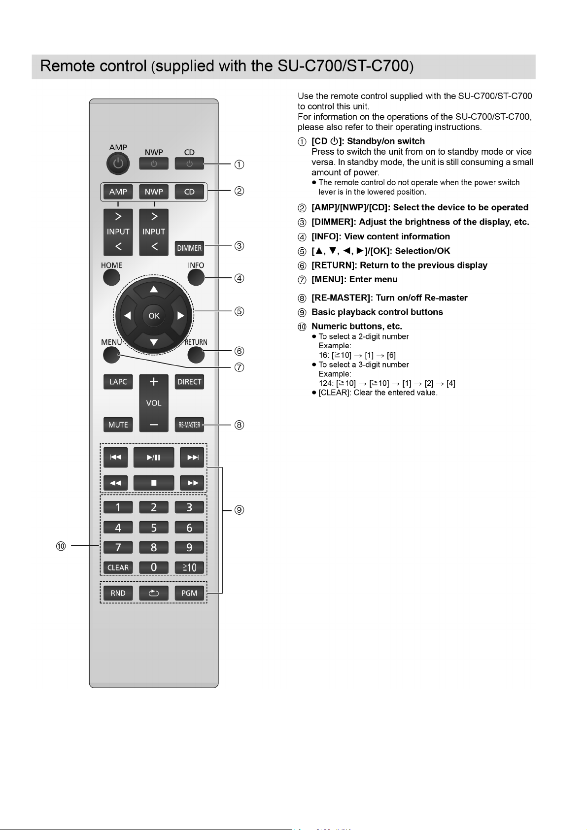
4 Location of Controls and Components
9
Page 10
10
Page 11
5 Troubleshooting Guide
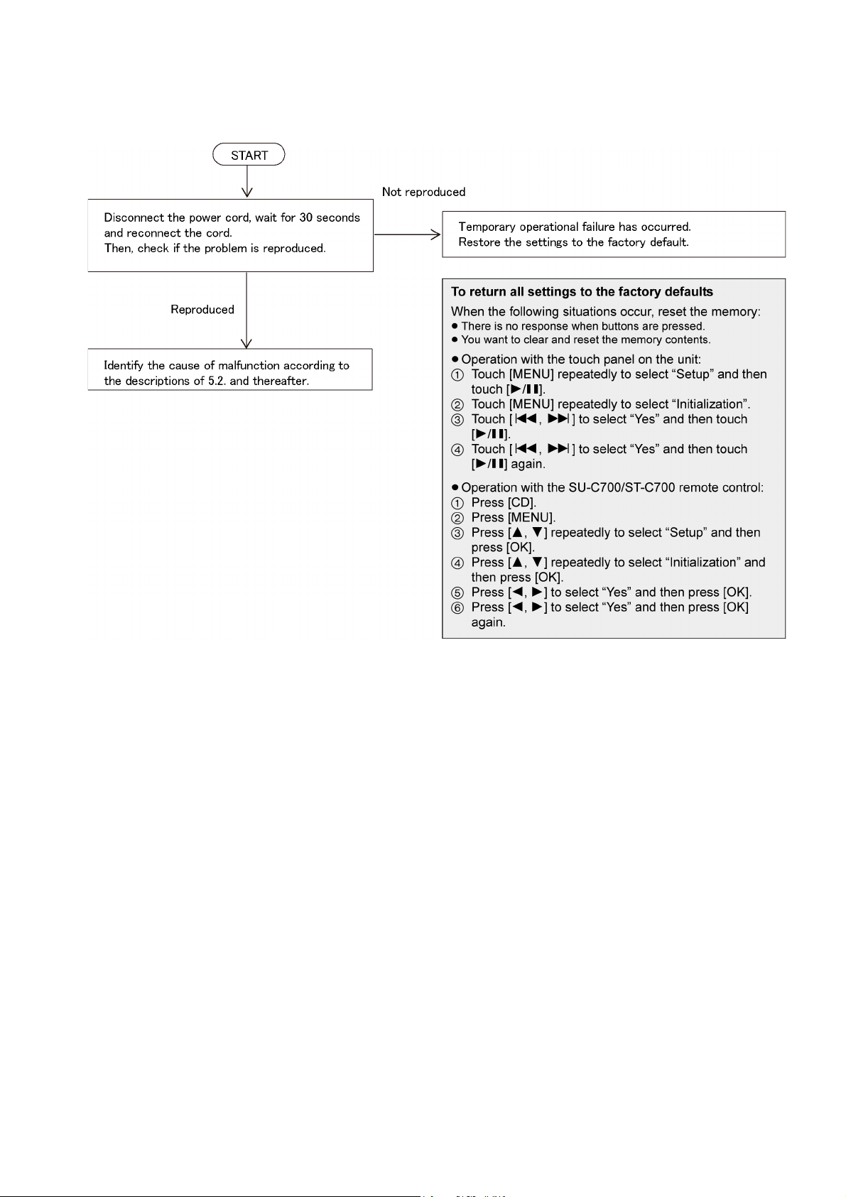
5.1. Check the problem is reproduced
11
Page 12
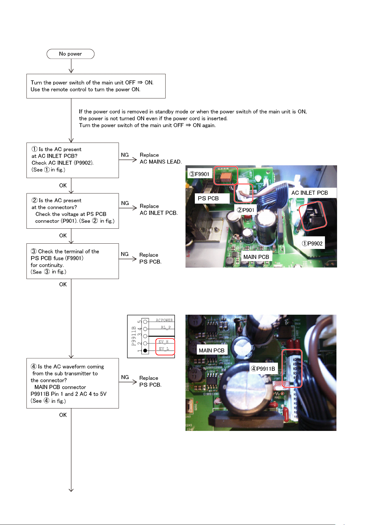
5.2 No power
12
Page 13
1314151617
Page 14

Page 15

Page 16

Page 17

5.3. LED does not illuminate
5.4. No buzzer
5.5. Remote control does not operate
Page 18

5.6. No Display
18
Page 19

5.7. No CD operation
19
Page 20

5.8. Connector pin configuration
20
Page 21

5.9. Blocks related to each function
21
Page 22

6 Disassembly and Assembly Instructions
22
Page 23

6.1. PCB layout drawing
6.1.1. Inside the main unit
23
Page 24

6.1.2. Front part
24
Page 25

6.2. Removing the disc when the disc cannot be removed using the opening-closing button
1. Turn OFF the main unit, and remove the AC cord.
2. Place the main unit in the way that its bottom can be seen.
3. Using a flathead screwdriver (small), slide the cam slide seen from the slit at the bottom of the deck in the arrow direction,
then slightly eject the tray.
4. The tray appears in front by approx. 1 cm. Holding the front part of the drive, pull it in the arrow direction lightly, and move the
tray.
25
Page 26

6.3. Disassembly flow chart
The following flow chart shows the procedure to disassemble exterior and interior parts for internal inspection.
Assembly is done in reverse order of the flow chart.
26
Page 27

6.4. SET LEG UNIT
1. Remove the screws for removal.
• Screw: 4
6.5. TOP AL PANEL
1. Remove the screws for removal.
• Screw: 4
6.6. TOP CABINET BLOCK
1. Remove the TOP AL PANEL.
(See 6.5. TOP AL PANEL, step 1.)
2. Remove the screws for removal.
• Screw: 9
6.7. SIDE PANEL (R), SIDE PANEL (L), TOP PANEL
1. Remove the TOP AL PANEL.
(See 6.5. TOP AL PANEL, step 1.)
2. Remove the TOP CABINET BLOCK.
(See 6.6. TOP CABINET BLOCK, step 2.)
3. Turn it over, and remove the screws for removal.
• Screw: 4
27
Page 28

6.8. FRONT PANEL UNIT
1. Remove the couplers.
• Coupler: P805A, P806A, P813A
6.9. TOUCH SENSOR PCB, PICT LIGHTING WINDOW
1. Remove the FRONT PANEL UNIT.
(See 6.8. FRONT PANEL UNIT, step 1 and 2.)
2. Remove the coupler, screws and F brackets for removal.
• Coupler: P805B
• Screw: 2
2. Remove the screws for removal.
• Screw: 8
3. Remove.
6.10. DISPLAY PCB, OLED ASSY
1. Remove the FRONT PANEL UNIT.
(See 6.8. FRONT PANEL UNIT, step 1 and 2.)
2. Remove the couplers and screws for removal.
*Remove binding wires as necessary.
• Coupler: P813B, P8881B
• Screw: 4
28
3. Remove.
Page 29

6.11. IR PCB, MAIN SWITCH PCB
1. Remove the FRONT PANEL UNIT.
(See 6.8. FRONT PANEL UNIT, steps 1 and 2.)
2. Remove the coupler and screws for removal.
*Remove binding wires as necessary.
• Coupler: P831B
• Screw: 7
3. Remove the solders (P951A and P951B).
Note when replacing the IR PCB and MAIN SWITCH PCB
• When replacing the IR PCB and MAIN SWITCH PCB,
remove the solder on the PCB to be replaced, and then
reconnect it again.
2. Remove.
Note when attaching the BELT LOADING
• When attaching the BELT LOADING, make sure there is no
twist or deflection.
6.14. CD MECHA BLOCK, DOOR
1. Remove the couplers.
• Coupler: P0102, P0103, P0104
6.12. FRONT PANEL ASSY
1. Remove the FRONT PANEL UNIT.
(See 6.8. FRONT PANEL UNIT, steps 1 and 2.)
2. Remove the TOUCH SENSOR PCB and PICT LIGHTING
WINDOW.
(See 6.9. TOUCH SENSOR PCB, PICT LIGHTING
WINDOW, steps 2 and 3.)
3. Remove the DISPLAY PCB and OLED ASSY.
(See 6.10. DISPLAY PCB, OLED ASSY, steps 2 and 3.)
4. Remove the IR PCB and MAIN SWITCH PCB.
(See 6.11. IR PCB, MAIN SWITCH PCB, steps 2 and 3.)
6.13. BELT LOADING
1. Stand the main unit carefully. Using a flathead
screwdriver, slide the lever of the cam slide in the arrow
direction. (The tray comes out approx. 1 cm as shown.)
2. Remove the screws for removal.
• Screw: 4
29
Page 30

Note when attaching the CD MECHA BLOCK
• When attaching the CD MECHA BLOCK, pass the FFC into
the gap between CD MECHA DRIVE PCB and MAIN PCB,
and then connect it to the "Coupler: P0102".
6.15. SPRING, CD LOADING UNIT
1. Remove the CD MECHA BLOCK.
(See 6. 14. CD MECHA BLOCK, DOOR, steps 1 and 2.)
2. Remove the coupler.
• Coupler: P105
6.16. INSULATOR, CD DRIVE UNIT
1. Remove the CD MECHA BLOCK.
(See 6. 14. CD MECHA BLOCK, DOOR, steps 1 and 2.)
2. Re move the SPRINGs and CD LOADING UNIT.
(See 6. 15. SPRING, CD LOADING UNIT, step 3.)
3. Remove the couplers.
4. Remove.
3. Remove the screws for removal.
• Screw: 4
Note when attaching the SPRINGs (SILVER) and (GOLD)
• When attaching the SPRINGs (SILVER) and (GOLD), make
sure each position is correct.
6.17. REAR PANEL
1. Remove screws A and screws B for removal.
• Screw A: 10
• Screw B: 2
30
Page 31

6.18. MAIN PCB
1. Remove the REAR PANEL.
(See 6.17. REAR PANEL, step 1.)
2. Remove the couplers and screws for removal.
• Coupler: P602, P805A, P806A, P813A, P0102, P0103,
P0104, P9911B, P9912B
• Screw: 5
6.19. SOFTWARE IN 1 PCB, SOFTWARE IN 2 PCB
1. Remove the REAR PANEL.
(See 6.17. REAR PANEL, step 1.)
2. Remove the MAIN PCB.
(See 6. 18. MAIN PCB, steps 2 and 3)
3. Remove the coupler and screw for removal.
• Coupler: P605
• Screw: 1
6.20. CD MECHA DRIVE PCB
1. Remove the couplers and screw for removal.
• Coupler: P0102, P106B, P107B
• Screw: 1
3. Remove the couplers and screws for removal.
• Coupler: P106B, P107B
• Screw: 2
Note when attaching the MAIN PCB
• When attaching the MAIN PCB, pass the FFC into the gap
between CD MECHA DRIVE PCB and MAIN PCB, and then
connect it to the "Coupler: P0102".
Note when attaching the CD MECHA DRIVE PCB
• When attaching the CD MECHA DRIVE PCB, pass the FFC
into the gap between CD MECHA DRIVE PCB and MAIN
PCB, and then connect it to the "Coupler: P0102".
31
Page 32

6.21. PS PCB
1. Remove the couplers screws and spacers for removal.
*Remove binding wires as necessary.
• Coupler: P901B, P9911A, P9912A
• Screw A: 2
• Screw B: 2
2. Remove the clamper.
Note when attaching the AC INLET PCB
• When attaching the AC INLET PCB, pass the wires to the
clamper, and then connect it to the "Coupler: P901B".
6.22. AC INLET PCB
1. Remove the coupler and screws for removal.
*Remove binding wires as necessary.
• Coupler: P901B
• Screw: 2
32
Page 33

7 Dimensions
33
Page 34

8 Block Diagram
34
Page 35

9 Wiring Connection Diagram
35
Page 36

Page 37

Page 38

Page 39

Page 40

Page 41

Model No. : SL-C700E Parts List
Change Safety
Ref.
No.
1 RKW1104-S FRONT PANEL ASSY 1
2 RGL0810-Q PICT LIGHTING WINDOW(LED) 2
3 RGR0480A-B REAR PANEL 1
4 RKA0235-S SET LEG UNIT 4
5 RGG0255A-S SIDE PANEL (L) 1
6 RGG0255-S SIDE PANEL (R) 1
7 RMA2508A TOP PANEL 1
8 RGG0269-S DOOR 1
9 RGG0254-S TOP AL PANEL 1
10 REE2104 FFC (CD MECHA DRIVE - CD MECHA) 1
11 REE2105 FFC (MAIN - SOFTWARE IN 1) 1
12 REE2106 FFC (MAIN - TOUCH SENSOR) 1
13 REE2107 FFC (MAIN - DISPLAY) 1
14 REE2108 FFC (MAIN - IR) 1
15 RAD2211-Z CD LOADING UNIT 1 E.S.D.
16 RMG1027-K BELT LOADING 1
17 RAM2211A-Z CD DRIVE UNIT 1 E.S.D.
18 RMG1028-K INSULATOR 4
19 RMB0997 SPRING (SILVER) 2
20 RMB0998 SPRING (GOLD) 2
21 RQLS0571 LABEL 1
PCB1 REP5260AA MAIN PCB 1 E.S.D.
PCB2 REP5260AB CD MECHA DRIVE PCB 1 E.S.D.
PCB3 REP5260AC DISPLAY PCB 1 E.S.D.
PCB4 REP5260AD TOUCH SENSOR PCB 1 E.S.D.
PCB5 REP5260AE MAIN SWITCH PCB 1 E.S.D.
PCB6 REP5260AF SOFTWARE IN 1 PCB 1 E.S.D.
PCB7 REP5260AG IR PCB 1 E.S.D.
PCB8 REP5260AH SOFTWARE IN 2 PCB 1
PCB9 REP5261AA PS PCB 1 E.S.D.
PCB10 REP5261AB AC INLET PCB 1 E.S.D.
PCB11 RSQ0141 OLED ASSY 1 E.S.D.
P1 SPG0330 PACKING CASE 1
P2 RPN2734 CUSHION 1
P3 SPF0045 POLY BAG 2
P4 SPH0016 SHEET 1
P5 SPQ0017 SHEET 1
A5 SQT0708 OPERATING INSTRUCTIONS (ENGLISH) 1
A6 SQT0709
A7 SQT0710
A2 K2KYYYY00251 COAXIAL DIGITAL CABLE 1
A3 K2KYYYY00233 SYSTEM CONNECTION CABLE (M3 CABLE) 1
A8 K2OQ2YY00127 AC MAINS LEAD (ROUND 2PINS) 1
A9 K2CT2YY00103 AC MAINS LEAD (RECTANGULAR 3PINS) 1
Part No. Part Name & Description Q'ty Remarks
OPERATING INSTRUCTIONS (GER_FRE_ITA
_SPA_DUT)
OPERATING INSTRUCTIONS (DAN_SWE_FIN
)
1
1
 Loading...