

Page 1

I
TêchnÍcs
Mrr.-v
Programmable
Unit
sH-go3a
OPERATING
INSTRUCTIONS
.. .: c.s
ccmpletely
Page 2
la
..\
'
!/)-,
.Y/,,,,,
--/2,,,
Your new
"Technics"
lvlicom
Programmable
Unit
was
manufactured
and assembled
under
exacting quality
control
standards.
The incorporation
of the latest
advances in
design and
the use of
the
most modern
components
assure
outstand¡ng
performance
with
superb
sensitivity
and
tonal
quality.
A few
minutes
of
your
time, wisely
spent reading
carefully through
this instruction
booklet,
will
assure
you
of
getting
the maximum
benefit
of this
fine component's
potent¡al.
CONTENTS
.
PRODUCT
SERVICE.
.
FEATURES
.
STEREO
SYSTEM COMPONENTS
AND
THEIR
CONNECTIONS.
. .
O
CONNECTIONS
.
FRONT
PANEL
CONTROLS
AND
THEIR
FUNCTIONS
.
OPERAT¡ON
.
OPERATION
NOTES
.
EXAMPLES
OF PROGRAMMING
PRODUCT
SERVICE
I,VARNING
CONCERNING
REM
OVAL
OF
COVERS
This
unit
should
be
serviced
by
qualified
technicians
only.
No
service
informat¡on
is
provided
for
customers.
Should
your
"Technics"
product
ever
require
servicing,
refer
to
the Directory
of Authorized
Service
Centers
or
your
franchised
"Technics"
dealer for
detailed
instructions.
LOCATION
OF
SERIAL
NUMBER
You will
find the serial
number
located
at
the bottom
of the
unit.
1
2
3
4
5
7
I
.
USE
OF UNIT'S
"FEET''
.
MOUNTING
IN
AN EIA-STANDARD
RACK
.
PROGRAM
TABLES
.
FOR
LONG
AND
SAFE USE
OF
THIS
UNIT
.
MAINTENANCE
OF
EXTERNAL
SURFACES
.
ACCESSOR¡ES
O
TECHNICAL
SPECIFICATIONS
...10
...11
....11
.,,...12
....13
....14
The model
number
of this
product
may
be found
on the back
of the unit; and
the serial
number
on the
label
affixed
to the
6s11ern of the
unit.
You
should
note
the
model
and
serial numbers
of this
un¡t
in
the space
provided
and
retain
this booklet as a
permanent
record
of
yQur
purchase
to
a¡d in identification
in the
event of theft.
MODEL
NUMBER-
SERIAL
NUMBER-
WARNING:
To
pREVENT
FIRE
oR sHocK
HAZARD,
DO NOT
EXPOSE
THIS UNIT TO RAIN
OR MOISTURE.
Page 3
FEATURES
COINCIDING
WITH
THE
BEGINNING
OF
THE
"MtcoM"
(MtcRocoMpuTER)
AcE.
.THE
TECHNICS
SH.9O38 PROGRAMMABLE
UNIT
The Technics
SH-9038
¡s
a
m¡crocomputer-controlled
programmable
unit
in
which
the
built-in
microcomputer
automat¡cally
controls
as many
as
32
programmed
in_
structions
during
a
one-week
period.
Unl¡ke the
convent¡onal
audio
timer-which
can
merely
be
set
for
one
on/off
operation
each
day-this
programmable
unit
can be
set
in
advance
to
perform
the instructed
oper-
ations
on
specific
days
during
the week
ahead (or
every
day)
at the
specified
time(s)
(programmable
in
segments
of one minute
each)
with
respect
to
any one
or more
of as
many
as I
preset
broadcast
stations,
and
in
conjunction
with
as many
as
4 connected
components (tuner,
amplifier,
tape
deck,
etc.)..with
a total
of
32
possible
pre-set
pro_
grammed
instructions possible
during
the next
7
days.
The Technics
SH-9038 is
the audio
component
which
has
introduced
the
"Micom"
(microcomputer)-a
device
which
because
of ¡ts extremely
compact
size and
precise
operation
has
such a variety
of
possible
uses-to
the aud¡o
world.
ln
order to real¡ze
the
maximum
versat¡lity
of
performance
of
which
this
unit is
capable,
it
should
be used
with
the
Technics
model
ST-9038
quartz-synthesizer
tuner
developed
espec¡ally
to be
a
part
of this
series
of high-quality
audio
com
ponents.
FM
MEMORY FUNCTION
PERMITS
PRESETTING
OF AS MANY
AS
8 BROADCAST
STATIONS
By
using
this unit
in
combination
with
the
Technics
model
ST-9038
tuner, as many
as I broadcast
stat¡ons
can
be
preset
into
the
"memory"
of this unit.
When
the
programming-mode
selector
of this
un¡t is
set
to
the
"FM
memory"
pos¡tion
and the
broadcast
station
is
tuned (on
the Technics
ST-9038)
and
preset
on this
unit, any
desired
stat¡on can
thereaJter
be selected
by a
single
touch.
32 PROGRAMMED
INSTRUCTIONS
FOR
A
ONE.
WEEK
PERIOD
As many
as
32 operat¡on
instruct¡ons
can
be
programmed
("written")
into the
unit's memory
for
subsequent
auto-
matic
operation during
the following
7
days.
When
the days, times,
broadcast
stations
and
onioff
operations
of other
components
(tuner,
amplifier,
tape
deck,
etc.) connected
to the
AC
outlets
of
this
un¡t are
programmed,
the
operation of
all components
(Technics
ST-9038
tuner,
amplifier,
and
other
equipment
connected
to the
AC1
and
AC2
outlets) witt
be
controlled
fully
auto-
mat¡cally,
including
automatic
station
selection
of the
model
5ï-9038 tuner.
AUTOMATIC
OR
MANUAL OPERATION
When
the
programming-mode
selector
is
set
to the
,,auto"
position,
this
unit
will
automatically
control
the operat¡on
of the
complete
audio
system
as
programmed.
At
the
"manual"
pos¡tion,
the
station
selection
and
AC
line
on/off
operations
can
be
performed
manually,
re-
gardless
of the
programmed
instructions.
When
the
programming-mode
selector
is
set to the
,,auto,'
position,
however,
note
that
any
desired
manual
operation
is.
possible
for
time
periods
for
which
the un¡t has not
been
programmed
to
operate,
but
pre-programmed
operat¡ons
will
automatically
begin
when
scheduled,
taking
pr¡ority
over the
manual
operation
in
progress,
if any. Thus
the
microcomputer
will
faithfully
execute any
and all
pre-
progra.mmed
commands,
even if
you
happen
to be listening
to
another
FM
broadcast
than
that
programmed.
lt never
forgets,
even
if
you
do.
EXTREMELY
PRECISE
TIME
DISPLAY
SHO\iVS
DAY
HOUR
AND
MINUTE
Th¡s
un¡t includeS
a time
display
which
is
synchron¡zed
with
the
power
supply
frequency
in
order
to
assure
an
extremely
small
degree
of error.
The
day
of
the week
is
indicated
by
a series
of LED indicators,
and
the
hour
and
minute
by
an
electronic
digital
display.
The correct
time
can
be
set very
easily
by
using
three
pushbuttons
(day,
hour
and minute).
lt ¡s
also
poss¡ble_by
setting the
time-mode
selector
to the
,,clock"
position
when
a rad¡o, TV
or
telephone
time
s¡gnal is
heard-to
set
the
unit to
the
precise
second.
..STOP-WATCH''
FUNCTION
SHOWS
TAPE
RECORDING
TIME
OR
TAPE-REMAINING
TIME
The
time
display
can
be used
to
give
an elasped-time
readout
of as much
as
59 minutes
and
59 seconds
after
start of operation.
After
t
hour has
elapsed,
the
reádout
returns
to
00:00 and
the
time
count
continues.
Note
that
this
unit
also incorporates
a
,,hold,'
function
which
can
be
convenienily
used
to stop
the time
count
temporarily
while
the
tape
deck
is in
the
,,pause"
mode,
thus
making
it
easy
to calculate
time
of
tape remaining.
OTHER
FEATURES
This
model
has
the same
slim,
d¡e-cast
cabinet
as the
Technics
model
ST-9038
tuner for
excellent
shielding
effect,
preventing
interference
to other
components,
and
also
shutt¡ng
out
external
signals
from interfering
with
micro-
computer
accuracy.
Special 16-pin
"bus-line"
terminal
is
provided
on rear
panel
for
connection
to
model
ST-9039
tuner.
a
Page 4

..STEREO
SYSTEM
COMPONENTS
AND
THEIR
CONNECTIONS
FM special antenna
75O
coaxial
cable
Stereo
pin-type
cord
(R)(L)
(
ITuner
input
terminats ("TUNER")
¡
Recording
term¡nals
("REC
OUT")
.(
Playback
terminals
("
pLAyBACK")
<
Speaker terminals ("R")
<
Speaker
terminals
("L")
t
FM stereo
tuner
(sT-9038)
Programmable
Unit
(sH-9038)
AC outlet
Pre/main
amplif
ier
(L)(R)
(L)(R)
To
"TUNER"
of SH-9038 v
To
AC
outlet
<_
:AC1">
.AN/P
"
>
û
a
Output
terminals
("LrNE
OUT")
lnput
terminals
("LrNE
tN")
>
û
(R)
(L)
Tape
deck
(L!
{Rì
To
"AC
1"
of SH-9038
^
G
N
D
{R)
(L)
d
^
Phono terminals
("PHONO")
To
"AMP"
of
SH-9038
@ì
@
To AC
outlets
of amplifier
Record
player
*The
AC1
and
AC2
outlets
are to
be used for connection
of a tape
deck, second
tuner, etc.
Speaker
systems
FM
antenna
terminat
(,,FM
ANT")
Output term¡nals
("OUTPUT'
16-p¡n
control
signal
line
terminal
Tuner input
terminals
("TUNER
lN'
')
Tuner output
terminals
("TUNER
OUT")
Recording ¡nput
terminals
("REC
lN")
16-pin
control
signal
line
terminal
Recording output terminals
("REC
OUT")
3
Page 5
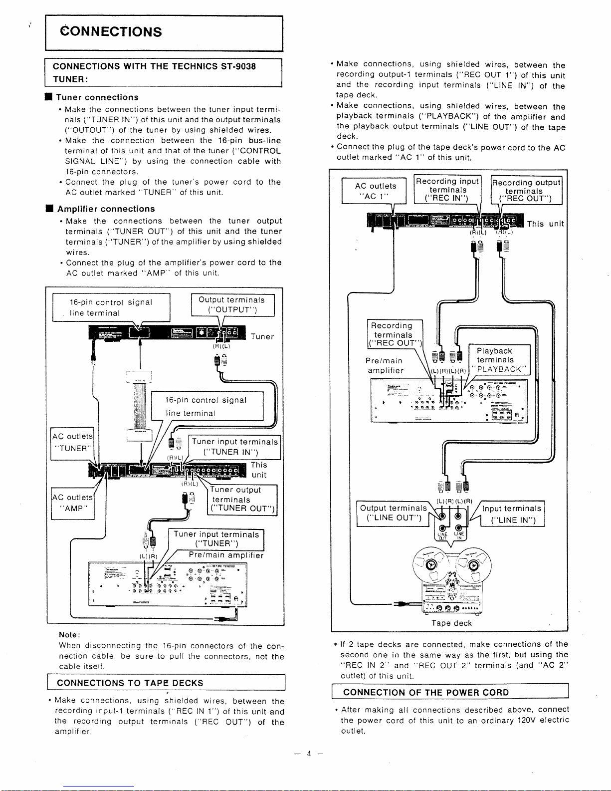
CONNECTIONS
CONNECTIONS
WITH THE
TECHNICS ST.9O38
TUNER:
I
Tuner
connections
.
Make the
connections
between
the
tuner
input
termi-
nals
("TUNER
lN")
of th¡s unit and the output term¡nals
("OUTOUT")
of the tuner by
using
shielded wires.
.
Make
the connection between the 16-p¡n
bus-line
terminal of this unit
and that of the tuner
("CONTROL
SIGNAL
LINE") by us¡ng
the connect¡on
cable with
16-pin
connectors.
.
Connect the
plug
of
the tuner's
power
cord
to the
AC
outlet
marked
"TUNER"
of this unit.
I
Amplilier
connecl¡ons
.
Make the connections
between the tuner output
terminals
("TUNER
OUT") of this
unit and the tuner
terminals
("TUNER")
of the
amplif
ier
by using
shielded
wires.
.
Connect the
plug
of the amplifier's
power
cord
to
the
AC outlet marked
"AMP'
of this unit.
Note:
When drsconnecting
the
16-pin
connectors
of the
con-
nection cable, be sure
to
pull
the
connectors, not
the
cable itself.
CONNECTIONS
TO TAPE DECKS
.
Make
connections,
us¡ng shielded wires,
between
the
recording
input-1
terminals
(
REC
lN 1")
of this
unit and
the
record¡ng
output
terminals
("REC
OUT")
of the
amplif ier.
.
Make connections,
using
shielded wires,
between
the
record¡ng
output-1
terminals
("REC
OUT
1")
of this
unit
and the recording input
terminals
("LlNE
lN")
of
the
tape deck.
.
Make
connect¡ons,
using
shielded
wires,
between
the
playback
terminals
("PLAYBACK")
of the
amplifier
and
the
playback
output terminals ("LtNE
OUT")
of
the tape
deck.
.
Connect
the
plug
of
the
tape
deck's
power
cord to the
AC
outlet marked
"AC
1" of this
unit.
*
lf 2
tape decks are connected,
make connections of the
second
one
in
the same way as the
first, but using the
"REC
lN
2'
and
"REC
OUT
2" terminals
(and
"AC
2"
outlet) of this
unit.
CONNECTION
OF THE POWER CORD
.
After making
all connections
described
above,
connect
the
power
cord of this un¡t to an ordinary
120V
electric
outlet.
4
16-pin
control
s¡gnal
line terminal
Output
terminals
("ouTPUT")
16-pin
control signal
line
terminal
Tuner
input
terminals
("TUNER
tN")
..TUNER''
outl
ïuner
output
te rm Inals
("TUNER
OUT")
,.AMP
outl
Tuner input
terminals
("TUNER")
oo-
='-:::-
.
*
---l
i-:::'
_4.
tt
oo
oô
Tuner
(Ri{L
n
amplitier(L)
(R)
n
I
-i
m
iRr
)
un¡t
IS
tE=
lnput term¡nals
("L|NE
¡N"
Output terminals
("LrNE
OUT")
AC outlets
"AC
1"
("REC
tN',
Recording input
terminals
ecord¡ng
output
term¡nals
("REC
OUT")
t-l
Recordi ng
terminals
.REC
OUT''
Playback
te rm¡na ls
..PLAYBACK,'
-9..J-
:
otto
'-o_ 2_ag
;9-9
-ô'ô
-ô-
Þ"¡-=l
This
unit
a
Pre/main
amplif ier
u
(R)(L) (R)
Ð
{L)(Rì
(L)(R)
Tape
deck
Page 6

FRONT
PANEL
CONTROLA AND
.THEIR
FUNCTIONS
Q
Programming-mode
selector
(program
mode)
This
selector
is
used
to select
the operation
mode:
FM
memory:
Set
to
this
position
to
"memorize"
the
broadcast
stat¡on(s)
to
be
received
by the
tuner
(Technics
model
sï-9038).
By
using
the ,1-8
preset
pushbuttons
G,
this unit
can
be
preset
for reception
of as many
as
g
FM
broadcast
stations.
manual:
Set
to
this
posit¡on
to manually
select
one of the
preset
stations
of the
tuner,
or to
use
(without
preprogramming)
equipment
connected
to
the AC
ouilets
of this
unit.
auto:
Set to
this
pos¡tion
for
automat¡c
control
of the
program-
med
operation
instruct¡ons
entered
("written")
with
this
selector
set
to the
"write"
position.
read:
Set to
this
position
to
conf¡rm
the
programmed
operation
instruction
entered
("wr¡tten")
with this
selector
set
to
the
"write"
pos¡tion.
When
the
step
pqshbutton
O
ls
pressed
once and
then
once again,
the
number
of each consecut¡ve
program-
med
operation
as
well
as the
programmed
operation
instruction
itself
will
be
indicated
in
consecutive
orderby
the
¡ndication
disptay
panel
g.
Note
that there
will
be no indication
by
the ind¡cation
display
panel
if no
operation
¡nstruction
has
been
entered
("written")
for
that
particular
programmed
operation number.
wrile:
Set
to this
position
to
enter
("write")
programm¡ng
operation
instructions
into
the memory.
As many
as
32 b¡ts
of
programming
operation
information
(one
bit, for
example,
consists
of day,
time,
broadcast
station,
and
power
"on"
or
"off")
can
be
entered into
the memory
for
the
coming
7
days. lf
an
error is
made
wh¡le
entering
the
programming
operation
instructions
¡nto
the memory,
that
programmed
operation instruction
only
can be
"erased"
f rom
the memory
by
pressing
the
cancel/reset
pushbutton
@.
reset:
To
"erase"
all
programmed
operation instructions
f
rom
the unit's
memory,
set
the
selector to this
position
and
press
the
cancel/reset
pushbutton
O.
Note, however,
that
the
broadcast
stat¡on
select¡ons
preset
(with
this
selector
set
to the
"FM
memory"
posit¡on)
will not
be
e
rased.
Time-mode
selector
8
FM-station
indicators
Timer-/time-set
pushbullons
lndication
display
panel
Day
indicators
All-powe
r-off
pushbutton
AC
:l/AC
2
power-on
pushbuttons
Amplilier
power-on
pushbutton
Time-programm¡ng
pushbuttons
Cancel/reset
pushbutton
Step
pushbutton
P rog ramming-mode
seleclo r
Presel
pushbuttons
IEÚfrã::t
5
Page 7

@
Step
pushbutton (step)
This
pushbutton
is
used to confirm what
operation
¡nstructions have been
programmed
into
the
memory.
When
the
programming-mode
selector
O
¡s
set to the
"read"
position
and this
pushbutton
is
pressed
once,
the number
of the
programmed
operation
will
be
indicated
by the
indication
display
panel
@.
When this
pushbutton
¡s then
pressed
once again, the time
of
that
programmed
operation will be indicated, and the
individual
indication lamps
will illum¡nate to indicate
the day, the selected
broadcast station, and
power
"on"
or
"off."
@
Cancel/resel
pushbutton
(cancel-resel)
Use this
pushbutton
if a mistake has been made
in'
programming
the
operation instructions, or ¡f it is
desired
to
"erase"
all
programmed
¡nstructions
(except
the
preset
broadcast
station settings).
@
Time-programming
pushbuttons
(lime-0-9)
During
programming,
use these
pushbuttons
to
program
the various
times of operat¡on.
@
Preset
pushbutlons
(presel-1
,-8)
lf
the
programming-mode
selector
O
is
set
to the
"FM
memory"
pos¡tion,
these
pushbuttons
can
be used
to
preset
the broadcast
stations into
the unit's
memory.
lf
the
programming-mode
selector
O
is
set
to the
"manual"
position
or
the
"auto"
posit¡on,
these
pushbuttons
can
be used for
selection
of
the
preset
broadcast
stations.
lf the
programming-mode
selector ¡s
set
to the
"write"
position,
these
pushbuttons
can be
used to
program
("write")
the day and
the
FM
broadcast
station into
the
unit's
memory.
@
I
FM-station
indicators
These indicators
will ¡lluminate
when
the
preset
pushbuttons
@r
are
pressed
to select
a broadcast
station.
Ø
Day
indicators
(week)
These
indicators
usually illuminate
to indicate
the
actual
day
of the week. lf
the
programming-mode
selector
O
¡s
set to the
"read"
or
"write"
posit¡on,
the indicator
corresponding
to the
selected
day will illuminate.
@
Amplifier
power-on
pushbutton
(on)
Use
th¡s
pushbutton
when
only the amplifier
(connected
to
the
"AMP"
AC
outlet)
is
to be turned
on
(but
not
off).
This
pushbutton
is
also used
during
programm¡ng
to
enter the
"on"
instruction into
the
unit's memory.
To
turn off the
power,
press
the
all-power-off
pushbutton
@.
€)
AC 1/AC
2
power-on
pushbuttons
(1
AC 2)
These
pushbuttons
are
to be used
to turn
on
(but
not
off) the
power
of equipment
connected
to the "AC
1"
and
"AC
2"
outlets.
These
pushbuttons
(one
or the
other,
or both) are also
used
during
programm¡ng
to enter
the
"on"
instruction
(used
together with
the amplifier
power-on
pushbutton
@)
into
the
unit's
memory.
To turn off the
power,
press
the all-power-off
pushbutton
,Te.
@
All-power-olf
pushbutton
(power
ofl)
Use this
pushbutton
when
the
power
of
all
AC
ouilets
¡s
to be cut
off.
This
pushbutton
is
also
used during
programm¡ng
to
enter
the
"off"
instruction
into
the
un¡t's
memory.
@
lndication
display
panel
ïhis
panel
shows
a
digital
display
of
information
de_
pending
upon
the
sett¡ng.s
of
the
programming_mode
selector
O
and
the time-mode
selector
@:
.
When
the
programming-mode
seleclor
O
is
set
lo:
The
"FM
memory,"
"manual,,'
..auto',
or
,.reset,'
position,
the
display
shows
the
present
time.
The
"read"
position,
the
display
shows
the number
of the
programmed
operation
and the
time
that
the
.
operation
has
been
programmed
to start.
'
The "write" posit¡on,
the
display
shows the
time to
which
the
programmed
operation is
being
program-
med
to start.
.
When
the time-mode
selector
@
is
sel
to:
The
"timer"
position,
the
counted
time
(See
page
7.)
will
be indicated.
The
"clock"
posit¡on,
the
present
t¡me will
be
indicated.
The
"time
set"
position,
the
time which
is
be¡ng set
will
be indicated.
@
Timer-/time-set pushbuilons
(t¡mer-time
set)
These
pushbuttons
are
used when
the
time is
being
set
and
when
the unit
is to
be used
as
a time
counter.
(See page
7.)
r
When
the
t¡me is
being sel:
Set the
time-mode
selector
@
to
the
"time
set"
posit¡on.
Use the
"start/week"
pushbutton
to
set the
day
of
the week.
Use
the
"hold/hour"
pushbutton
to set
the hour.
Use the
"reset/minute"
pushbutton
to set the minutes.
.When
the un¡t is
to be
used as
a time
counter:
Set the t¡me-mode
selector
@
to the
"timer"
pos¡tion.
The
t¡me count will
begin
when
the
"start/week"
pushbutton
is
pressed.
The time
count will
stop
when
the
"hold/hour"
pushbutton
¡s
pressed.
The display will
return
to the
"
!:
nl
"
indication
when
the
"reset/minute"
pushbutton
is
pressed.
@
Time-mode
selector
(time
mode)
This
selector
is used
to select
the desired
operation
of
the
clock.
timer:
Set to this
pos¡tion
for time
counting.
The indication
will
show minutes
and
seconds.
clock:
Set to this
position
to use
the time
display as an ordinary
clock.
t¡me
sel:
Set to this
position
when
the t¡me sett¡ng
is
being
adj
usted.
Note that
the
time count¡ng function will be stopped
when
the selector
is
set
to this
position.
Page 8

OPERATION
The following
explanation
of operat¡on
procedures
is based
on
the
assumpt¡on that
this unit is used
together with
the
Technics model
ST-9038 FM
stereo tuner.
We
suggest that th¡s
unit
be used
with
model
ST-9038 in
order to
obta¡n
the
maximum
benef¡t of all
of the many
features
of
this
unit.
SETTING THE
CLOCK
TO THE
CORRECT
TIME
When the
power
cord
of this
unit
is
connected
to an electric
outlet, the ¡ndication
"
f f
:f
f
"
witt
be disptayed
on the
indication
display
panel
@
if
the time-mode
selector
@
is
set to
the
"clock"
or
"timer"
position.
When
the time-
mode
selector is
set
to the
"time
set"
position,
"tr:!!"
will be
displayed,
and the
t¡me can
be correcily
set
by
following
these
steps.
Note
that
the display
panel
shows the time
by the
24-hour
day system:from
0:00
to 23:59. Thus,3:30
PM
would
be
ind¡cated
as 15:30,
and settings
should
be made
ac-
co rd ing
ly.
1)
Set the
programm¡ng-mode
selector O to
the
"manual"
or
"auto"
position.
2)
Set the
time-mode
selector
@
to
the
"t¡me
set"
position.
3)
Using the timer-/time-set
pushbuttons
@:
'1.
Press
the
"start/week"
pushbutton
to set
the un¡t to
the
day of the
week.
2.
Press
the
"hold/hour"
pushbutton
to
set the unit to
the correct hour.
3.
Press
the
"reset/m¡nute"
pushbutton
to set the unit
to the
correct minute.
When
these
pushbuttons
are
pressed
(in
the order
described
above),
the day, the hour
and the m¡nute w¡ll
change
continuously
until
the button is released.
Note
that the
above
order
of adjustment must be
followed;
the hour
can't
be changed after the minute,
nor
the
day after
the hour.
4)
Set
the
time-mode
selector
@
to the
,'clock"
pos¡tion.
Ihe
clock
will
not
operate
if the
time-mode
selector is
left
set
to the
"time
set"
pos¡tion.
Note
that
the clock
can
be
made
to start
most
precisely
by
setting
the
time-mode
selector
to
the
"clock"
position
precisely
when
a
time
signal
(f
rom
radio, TV
or
ielephone)
is heard.
(You
may,
therefore,
in
anticipation
of do¡ng
so,
want
to
make
the
sett¡ng
described
in
3)-3
a
minute
or so
ahead
of actual
time.)
Examples:
Therefore,
to
set the
display
to
3:30
pM
Wednesday:
1
)
Set
to
"manual"
or
2)
Set to
,,time
set"
pos¡tion
"auto"
position
4)
Set
to
"clock" position
when
time si
gnal
is heard
3-2)
Press
and
3-3)
Press and
hold.
(Release
3-1)
Press
and
hold.
(Release
when
"Wed"
¡nd¡cator
illu min ates.)
hold.
(Releas"
when
"30"
is
wheni,15,, ¡s
displayed.)
displayed.)
co
ù
tÆ
TO
USE
AS
A TIME
COUNTER
The
clock
of this
unit
can also
be
used much in
the
same
way
as
a stop-watch,
thus
making ¡t
convenient
to measure
tape
recordrng
ttßtes.
to measure
ttme
remaining
on
a
tape, etc.
1)
Set the
programming-mode
selector
\D
to the
,,manual,,
or
"auto"
pos¡t¡on.
2)
Set
the
time-mode
selector
@
to the
,,timer"
posit¡on.
3) Use the t¡mer-/time-set
pushbuttons
@
as
described
below.
1.
The
(a)
area
is for
display of
the hour(s),
and
(b)
for
display
of the
minutes.
lf the
counted
t¡me
exceeds
59
minute(s)
and
59 seconds,
the
display will
change
to
"
l:nn"
and counting will
continue.
2. Time
counting
will
begin
when
the
,,start/week,,
pushbutton
is
pressed.
3. Time
counting
can
be stopped
by
pressing
the
.,hold/
hour"
pushbutton.
4. The
d¡splay
can
be returned
to
the
.,!:n!"
¡n¿i-
cation
by
pressing
the
,,reset/minute"
pushbutton.
Note:
1.
lf the
"hold/hour"
pushbutton
is
pressed
after
t¡me
count¡ng
has
started,
the time
counting
will be
tempo-
rarily
stopped.
When
the
"startiweek"
pushbutton
¡s
once
again
pressed,
t¡me count¡ng
w¡ll
resume
(and
the
total
accumulated
time will
be
displayed).
2. lf the time-mode
selector
@
is
set
to
the
,'clock,'
position
durîng
time counting,
the time
count¡ng
operation
will
be
temporar¡ly
stopped.
lf it is
then
once
again
returned
to the
"t¡mer"
position,
t¡me
counting
will
resume
from
the
point
where
the change
was
made
to the
,,clock,'
position.
3.
lf the
time-mode
selector
@
is
set
to
the
,,time
set',
position
during
time
counting,
the
time
count¡ng
operation
will be
stopped.
The
time
counting
will
not
resume
even
¡f
the selector
is reset
to the
"timer"
position:
the
,,start/
week"
pushbutton
must
be
pressed.
TO
PRESET
TO BROADCAST
STATION
FREOUENCIES
By
simply
presetting
th¡s
unit
beforehand,
broadcast
stations can
be
easily selected
without
tuning
the
tuner
each time.
This
unit
can be used for
presett¡ng
as many
as g broadcast
stations.
1) Set the
programming-mode
selector
O
to
the
,,FM
memory"
position.
2) Tune the
tuner
(Technics
model
ST-9038)
to the désired
broadcast
station
frequency,
and
then
þress
one of the
eight
preset
pushbuttons
@.
When
one
of these
pushbuttons
is
pressed,
the cor-
responding
indication
lamp
will illuminate
to show
that
the information
has
been
programmed
¡nto the
unit's
memory.
As an
example,
suppose
you
want
to
program
the
following
broadcast
station
f requencies:
To conf¡rm
that sett¡ngs
have
been correctly made, set the
programming-mode
selector
O
to the
"manual"
or
"auto"
position,
and then
press
the
preset
buttons
@.
The
preset
broadcasts
will
then
be heard.
lf
one
preset
button
is set for
two different
broadcast
stations,
the second
setting will
have
priority
and
be
programmed
into
the
unit's
memory.
7
\_,,
\J
_q
oo
oo
o3
aooa
o
)
Set to
"FM
memory"
position
After
tuning to each
broadcast
frequency,
press
the respect¡ve
preset pushbutton.
2
1
88,1 MHz
92,1 MHz
1 MHz
Page 9

MANUAL
OPERATION
Set.lhe
programming-mode
selector
O
to
the
"manual"
position.
I
To
use lhe
tuner
Press the
i1-8
preset
button
O
corresponding
to
the
broadcast
stat¡on
to be heard.
When
one of
the
preset
buttons
@
is
pushed,
the
power
to the tuner
and to the
amplifier will
be turned
on at
the
same t¡me.
Then
operate the
amplifier
so that the broadcast
can
be satisfactorily
heard.
I
To
use the ampl¡lier
Press
the
amplifier
powér-on
pushbutton
@
to turn
on
the
amplif ier.
The
power
to a record
player
or other equ¡pment
will
thus
be
turned on if it
is
connected to the
AC outlet
of
the
amplif ier.
I
To
use equipmenl
connecled
to the
"AC
1"
or
l'AC
2"
outlets
The
power
to a tape
deck
or other
equipment connected
to
the
"AC
1"
or
"AC
2"
outlets
of
this
unit can be turned
on
by
pressing
the
AC 1
and/or AC 2
power-on
pushbutton(s)
6)
I
To turn off
the
power
To turn
off the
power
after
the
FM
broadcast, disc
per-
formance,
etc.
has
finished,
press
the all-power-off
push-
button
@.
It
the operation
of
connected
equipment has
been auto-
matically
started
(with
the
programming-mode
selector
O
set to the
"auto"
position),
set it
to the
"manual"
pos¡t¡on.
This unit
c be
used
to automatically
control the
complete
operat¡on of
an audio
system
by
simply entering
the neces-
sary
programming
instructions
into
the memory
of this
unit,
and
turning
on the
power
of the tuner,
amplifier,
tape
deck,
etc.
As many
as
32 operation
instructions
can
be
programmed
into
the
unit's memory
for
a one-week
period.
Follow
the
procedure
below
to
program
each
operation
¡
nstruction.
1)
Set
the
programming-mode
selector
O
to
the
,,write"
position.
2) To
program
the
day(s)
of
the
week
on
which
the operation
is to
occur,
press
the
appropriate
one
(or
more)
of the
eight
preset
buttons
@.
Note
that the
preset
button
marked
"everyday"
can be
used
to
program
the unit
to
perform
the
same
operation
at the same
time
every
day.
3)
Press
the appropr¡ate
four
(of
nine)
time-programming
pushbuttons
@
to
program
the
t¡me
at
which
the
operation is
to
occur.
4) Press
the appropriate
one
(of
eight)
preset pushbuttons
@
to select the
broadcast.
(This
step ¡s not necessary
if
the tuner
is not
to be used.)
5) lf
one
(or
two)
tape
deck(s) is to
be used
for recording,
for
example,
press
the appropriate
AC 1
and/or
AC 2
power-on
pushbutton(s)
.9.
(This
step
¡s not
necessary
if
the
equipment connected
to
the AC
outlets
is not
to
be used.)
6)
Finally,
press
the
amplifier
power-on
pushbutton
@.
Note
that steps 4)
and 5) are
not
necessary
(and
the
all-power-off
pushbutton
,G,
should
be
pressed
¡nstead
of
the
amplifier
power-on pushbutton
@)
if
the
"off"
command is
to be
programmed.
Examples:
(A)
As
the first
series of
ins_tructions
to be
programmed,
the
tuner
is to be turned
on to hear
the
broadcast
on
the frequency
designated as
2
at
9:31 AM
on
Sunday,
and, at the
same time, the tape
deck
connected
to the
"AC
1"
outlet
is to
be turned
on to record
this broadcast.
(B)
The second
series
of
instructions
to
be
programmed
is
to turn
everything
off at 10:30 AM
Sunday.
ln the
same
way
as
(A)
and
(B)
above, which
are
in total
2
sett¡ngs,
as
many
as
30 more
programmed
sett¡ngs
can
be made.
Notes:
1. When
the amplifier
power-on
pushbutton
@
or the
all-power-off
pushbutton
@
is
pressed,
all indication
lamps
will
be
extinguished
(to
indicate
that the first
series
of
programmed
instructions
has
been
completed).
2. When
an
"on"
or
"off"
command for
a series
of
pro-
grammed
instructions
¡s
entered,
the unit automatically
moves
on to the next
series,
so instructions
can
be
cont¡nuously
programmed.
3. lf a mistake
is made
wh¡le
instructions
are
being
pro-
grammed,
press
the
cancel/reset
pushbutton
@,
and
start again f rom
the
beginning. lf
all necessary
buttons
up to
and including
the
amplifier
power-on
(or
all-
power-off)
pushbutton
have
been
pressed,
the
number
of the
programmed
series
has
already advanced, and,
therefore, the
programming-mode
selector
O
should
be set to
the
"read"
position
to return
(to
the
previous
programmed
series
number),
then once
again set to the
"write"
position,
and
the
cancel/reset button
@
should
be
pressed.
4. To
confi
rm
that
programmed
instruction settings
have
been made
correctly,
reset the
programming-mode
selector
.î
to tfie
"read"
position
once
again
and
press
the
step
pushbutton
O.
After
the
programmed
¡nstruct¡ons have
been thus
conf irmed.
push
the
step
pushbutton
,2
to cont¡nue
programming,
and. after
the
program
number
has
advanced
to
an unprogrammed number, set
the
pro-
gramming-mode
selector
C)
to the
"write" position.
'@¡:
o
c
o
o
ooo
.
1) is to
be
pressed
to
program
the
unit for
Sunday.
.2),
3),
4)
and 5)
are to be
pressed
¡n
that order
for
9:31 AM
operation.
.
6) is to be
pressed
to
program
the
unit to
select
the broadcast
frequency
designated
as
2.
.7)
is
to be
pressed
to
program
the
unit to turn
on the
power
of
the
tape
deck
onnected to the
"AC
1"
outlet.
.8)
is
to
be
pressed
to
program
the unit
for
"on"
operation
of steps 1)-7).
l)
3)
7)
8)
Ð
s)6)4)
TO PROGRAM
OPERATTON
INSTRUCTIONS
o
@r:
o oo
o
:
o
5) 3)
)
)
.
1) is to
be
pressed
to
program
the un¡t for Sunday.
.
2), 3), 4) and
5) are
to be
pressed
in that
order for
10:30 AM
operat¡on.
.
6)
is
to be
pressed
to
program
the un¡t for
"off"
operat¡on.
I
Page 10

OPERATION
(continued)
TO
TAPE RECORD
A RADIO BROADCAST
WHILE
LISTENING
TO DISCS-
This
unit includes
circuitry
which makes
it
possible
to
listen
to
discs while tape recording
a radio broadcast.
IN
CASE
OF A POWER
INTERRUPTION
lf
there has
been
an ¡nterruption
of
the
power,
a special
indication (
[ [:f
f
)
wiil
appear
on the indication
disptay
panel
@.
alter
power
¡s resumed.
to ¡ndicate
that
there has
been
an ¡nterrupt¡on
of the
power.
lf
this
indication
appears,
the ciock
setting and
all
program-
med
instructions
have
been
erased.
so
¡t wìll
be
necessary
The unit is designed
so
that tuner
¡nput
s¡gnals
are
direcily
em¡tted from
the
"REC
OUT"
terminals
of th¡s
un¡t
when
the unit is
operating
in
the
"auto'
mode.
Thus,
recording
is
possible
only w¡th
an
amplifier
for
wh¡ch
the tuner
input
terminals
are not
shorted
when
the
selector
of the
amplifier
is
set
to the
,,phono"
posit¡on.
For
example.
our
models
SU-80g0,
SU-9070,
SU-82OO,
su-8600,
su-3500,
su-3200,
su-9400,
su_9200,
etc.
to set the t¡me
and
enter
all
programm¡ng
instructions,
as
Cescribed
on
previous
pages,
from
the
beginning.
Note,
however.
that
(because
of the
"back-up"
power
supply of the
Techn¡cs
model
ST-9038
tuner) the
selected
settinqs
of
FM
broadcast
stations.
as made
by the
preset
pushbuttons
,1
,
will
remain
¡n this
un¡t's memory
c¡rcuitry,
even though
a
power
interruption
occurs,
and thus
these
sett¡ngs need
not
be made
again.
lnput signals
from
tuner
To
"TUNER"
terminals
of amplifier
From
"REC
OUT"
terminals
of amplifier
t
REC IN
tl,
r?t
LRL
To
"LINE
lN'
of tape
deck
t
terminals
I
I
REC
OUT
TUNER IN
LR
TUNER
OUT
LR
rl
:).
R
R
L R
L
manual
ï
au to on
nranual
auto
on
maôual
aL¡lo on
n¡artual
au to
on
OPERATION
NOTES
Note
that
the
following
are noi
matfunctions
of
this un¡t.
1)
Every
time
the
setting
of the
programming_mode
selector
.!
is
changed.
the
power
to equipment
connected
to
the
AC
outlets (such
as
a tuner.
amplifier.
etc.) is
cut
off.
(The
power
will
not
be
cut
off. however.
at
the
,,FM
memory"
position.)
2)
When
the
programming-mode
selector
J
is
set
to
the
"auto"
or
"manual"
posit¡on:
lf
the FM
broadcast
stations
are
selected
by
using
the
preset
buttons
.5 :
lf
the
programming-mode
selector
is
then
set
to
the
"FM
memory" position,
the frequency
to which
the
íg
button
has
been
set
wiil
be indicated
by the
indication
display
panel
(or,
if
there
has
been
no
setting
made
for
the
i8
preset
button:
90..1 MHz or other
display).
lf
you
try
to
program
that
(¡ndicated)
f requency
¡nto
the
memory
by
pushing
the
appropriate preset
button
@,
the
frequency
may
change.
and
the
new
frequency
may
therefore
be
programmed
into
the memory.
To
prevent
this,
tune
the tuner
to the
correct
frequency
before
attempt¡ng
to
program
it into
the
memory.
lf
the
FM
broadcast
stat¡ons
are
selected
by
using
the
automat¡c-tuning
button
of
ih-e
tuner:
lf
the
programming-mode
selector
,J
is
then
set
to
the
"FM
memory"
posit¡on,
the
f requency
will
be
received
as
tuned,
and
can
be
programmed
into
the
memory.
3) lf,
with
the
programming-mode
selector
O
set
at the
''auto"
or
"manual"
pos¡t¡on,
a no-sett¡ng-made
preset
button
@
is
pushed,
¡ncorrect
display
may
be
provided
on the
¡ndicat¡on
display
panel
@.
a)
lf the
programming-mode
selector
O
is
changed
f rom
the
"auto"
position
to any
other
posit¡on
and
then
reset
to
the
"auto"
position
within
the first
one
minute
after
automatic
"on"
operation
has
started,
the
automat¡c
operation
w¡ll
continue.
lf, however,
the
selector
is
returned
to
the
"auto"
position,
or if it
is
moved
from
the
"auto"
position,
after
that
first
one minute
has
elapsed,
the
automatic
operation
will
stop.
For
a 12:01
setting,
for
example,
during
the first
one
minute
only
(until
becoming
.12:02),
the
automatic
operation will
be
possible
if
the
selector
is
returned
to
the
"auto"
pos¡tion,
but not
after
the time
becomes
12:02.
5)
Manual operation
is
possible
(with
the
programming_
mode
selector
O
set
to
the
,.auto"
position)
during
time
periods
for
which
the
un¡t is
not
programmed
to
be
in
operation,
except
during
the
first
one
minute
after
the unit is
programmed
for
an
automatic-off
operation.
6)
The
"t¡mer"
(or
"clock")
indication
seen in the indication
display
panel
@
indicates
the
pos¡tion
sett¡ng
of
the
time-mode
selector
@.
This
illuminated
indication
will
be seen,
therefore,
regardless
of
the
posit¡on
sett¡ng
of the
programming-
mode
selector
0.
7)
I'l
an automatic-on
operatron
and an
automat¡c-off
operation
are
programmed
to
occur at the
same
time,
the
automatic-on
operation
will
have
priority.
9
Page 11

EXAMPLES
OF
PROGRAMMING
Examples
of
programming
operation
instructions
into
the
memory,
and
operation
with
the
programm¡ng-mode
selector
O
set
to the
"auto"
pos¡tion,
are shown
below.
Program
No.
Day
Time
Station
AC
Power
on/off
1
every
day
-l:[[
1
on
2
every
day
-l:
Lll
Sun
lI:!l
3
AC1
on
4 Sun
ll:!l
2 on
5
Sun
ll:!l
off
6
Sun
l!:
!!
2
on
7
Mon
ll:
!!
1
AC1 on
a
lvl
on
1-. T-]a_)
-Li.
ul_l
2
on
I
Tue
El:
ll
2
on
10
Tue
=l.t-
Li
-JLI
J
on
'11
Wed
lE: lI
1
on
12
Wed
-ì.
--
-r.!r
i
off
Prog
ram
No.
Day
Time
Station
AC
Power
on/off
't3
Thu
E[:!!
1
on
14
Thu
El:ll
off
15
Frí
lE:!n
1
on
16 Fri
E!:!!
3 on
17 Fri
ll:!n
off
18
Sat
l::!n
2
AC1 on
'19
Sat
ì4:l!
off
31
Sat
lE:!l
2 on
32
eve
ry
day
Il:
ltr
off
ïime
Day
7:00
8:00
9:00
10:00
11:00
12:00
13:00
14:00
15:00 16:00
17:00 18:00
19:00
20:OO
21:00
22:00
Stat
on2
Sun
Stati
AC1
Stati on
J
Station 2
Station
2
Mon
Station
1
AC1
Tue
Stat¡on 1
3
Station
1
Wed
nt
Thu
Station
1
Station 1
Stat¡on
1
Stat
on3
Fri
Stati
Station
2
Sat
n1
AC1
Station 2
-
10
-
Page 12

I
Spaces
between
equipment
when
stacked
.
Using high feet
.
Using low feet
USE
OF
UNIT'S
"FEET"
This unit is
equipped
witli
2
groups
of feet:
one
group
higher
than
the
other.
(The
lower
feet
are included within
the higher
ones.)
Remove
the h¡gh
feet
and
use the low
ones when:
O
This
un¡t
and
the Technics
model
ST-9038
(of
the same
series)
are stacked
together.
@
This
unit is mounted
in
an audio rack
and the high
feet
don't
fit well.
MOUNTING
IN AN
EIA.STANDARD
RACK
When
this unit is
mounted
in
an
E|A-standard
rack,
use
the
included
rack-mount¡ng
adapters.
ATTACHMENT
OF
RACK-MOUNTI
A
o
lnsert
the adapters
into
the
sides
of
this
unit,
with
the
notched
part
of the
adapter
at
the
bottom.
O
Use the
hexagonal
wrench
to
tighten
the 4-mm
screws
in
order to
secure
the adapters
¡n.place.
(Left
and right
adapters
are
attached
in
the same
way.)
Note:
Be surethe
screw
heads
are not
inserted
beyond
the
un¡t
su
rface.
MOUNTING IN EIA.STANDARD
RACK
Place
a
metal
washer
and fiber
washer
on each
of the
included
S-mm
bolts,
and use
the
hexagonal wrench
to
attach the unit
to the
rack
as shown
in the figure.
9mm
1mm
Notes:
1. lf
this
unit is mounted
in
an E|A-standard
audio rack,
use
the included
rack-mount¡ng
adapters.
2. lf
this
unit is
stacked
with
an integrated (pre/main)
amplifier
or a
power
amplifier,
be sure not
to remove
the
high feet,
because
the radiated
heat
may adversely
aff
ect the
operation
of this
unit.
mm
mm
2-mm hexagonal
wrench
t-4nttt"l
4-mm
screws
C:)
h
Bottom
of unit
Rack-moünting
adapter
Hole
4-mm hexagonal
wrench
.:
f3
¡
S-mm bolts
(4)
Metal
washers
(4)
Fiber washers
(4)
t
?
à
-
11
-
Page 13

PROGRAM TABLES
Program
No.
Day
Time
Station
AC
Power
on
/of
f
1
ot\
/
oÍf
2
J
4
5
6
7
8
10
11
12
13
14
15
16
Prog
ram
No.
Day Time
Station
AC
Power
on /of
f
17
or\
/
orf
18
19
20
21
22
23
24
25
¿o
28
29
30
31
32
me
Day
6:00 7:0c
8:c0 9:00 lc:c0
ll:c0 l2:cc 13:00
14:0c
15:00
16:0c
t7:00
t8:oo
19:00
20:00
21..00
22:00
23:c0 24:00
Sun
Mon
Tue
Wed
Thu
Fri
Sat
-12-
Page 14

FOR
LONG
AND
SAFE
USE
OF
THIS
UNIT
1)
USE AN
ORD|NARY HOUSEHOLD
AC POWER
SOURCE
I
Use
lrom
an AC
power
source
ol high
vollage,
such as
for
air
conditioners,
is
very
dangerous.
Be
extremely
careful
not
to make
a connection
to
the
electr¡cal
outlet
for
a large
âir
conditioner
or central-
heat¡ng
unit which
uses
high voltage,
because
there is
the
possibility
of f ire.
I
A DC
power
source
cannot be
used.
Be
sure to
check the
power
source
carefully, espec¡ally
on a
ship or
other
place
where
DC
is
used.
2)
CONNECTTON
AND
DTSCONNECTTON
OF THE
POWER
CORD
PLUG
I
Wel
hands
are dangerous.
A
dangerous
electr¡c
shock
may result
if
the
plug
is
touched
by wet
hands.
I
Don't
pull
the
power
cord.
Always
grasp
the
plug;
never
pull
the cord itself.
3) AC
OUTLETS
ON REAR PANEL
I
Any
equipment
connecled
here should have
specified
power
consumption or less.
These
outlets are
exclusively
for
the
connection of
other
audio
equipment,
such
as a tape deck. Be sure the
power
consumption
of each
does not
exceed
wattage
specified
near
the AC outlets.
I
Never
connecl
other
eleclrical appliances such
as
an iron
or toaster.
lf
appliances
w¡th
a large
power
consumption are con-
nected,
an
unexpected
accident
m¡ght
occur as a result
of
overheating.
4)
NEVER
ATTEMPT
TO REPAIR OR RECON-
STRUCT
THIS
UNIT
A
serious
electric
shock might
occur if
this un¡t
is
repaired,
disassembled
or reconstructed
by
unauthorized
persons,
or if
the
internal
parts
are accidently
touched.
5) FOR
FAM¡LIES
WITH
CHILDREN
Never
permit
children to
put
anything,
especially
metal,
¡ns¡de
this
unit. A serious
electric
shock or malfunction
could
occur ¡f
art¡cles such
as
coins,
needles,
screw-
drivers,
etc.
are
inserted
through the ventilation holes,
etc.
of this unit.
6)
IF WATER
IS SPILLED ON THE UNIT
Be
extremely
careful
if
water is
spilled
on
the
unit,
because
a fire or
serious electric shock might
occur. lmmediately
d¡sconnect
the
power
cord
plug,
and
consult
with
your
d eale
r.
DC
-
13
-
4
x
=€
Þ-
Page 15

7)
PLACE THE UNIT
WHERE lT
WILL
BE WELL
.VENTILATED,
AND AWAY FROM D¡RECT
SUNLIGHT
Place
this unit at least 10 cm
(4")
away f rom wall
surfaces,
etc.,
and
away f rom direct sun¡ight.
Be careful
that curtains
and
similar
materials do not
obstruct the ventilation holes-
8)
KEEP
THE UNIT AIiVAY FROM STOVES, ETC
Heat
can
damage
the external surfaces as well
as ¡nternal
c¡rcu¡ts
and
components.
9)
AVO|D
SPRAY-TYPE |NSECT|C|DES
lnsecticides
m¡ght
cause cracks or
"cloudiness"
in
the
cab¡net
and
plastic parts
of this unit. The
gas
used
in
such
sprays might, moreover, be ignited suddenly.
10)
NEVER
USE ALCOHOL
OR
pAtNT
THTNNER
Ihese
and similar
chemicals
should
never
be used,
be-
cause
they may
damage
the
f inish.
IF TROUBLE OCCURS
lf,
during operation,
the sound is interrupted
or
indication
lamps no
longer ¡lluminate.
or if
abnormal
odor or smoke
is
detected, ¡mmediately
d¡sconnect the
power
cord
plug,
and
contact
your
dealer or an Authorized
Service Center.
7
(r
x
t
It
P
0¡
I
x
7
q
\ì00t
9
x
ì
10
x
MAINTENANCE
OF
EXTERNAL SURFACES
.
To
clean, use
a
soft,, dry cloth.
lf
the
surfaces
are
extremely dirty, use
a soft
cloth soaked
in
a detergent
(such
as
used
for washing
d¡shes;
diluted
to
1/5 or 1/6
strength), and
then wring
the
cloth well.
Wipe
once
again
with
a
soft, dry cloth.
.
Never
use chem¡cals
such
as alcohol,
pa¡nt
thinner
and
benzine,
nor a
chemically-treated
cloth
to
clean this unit
because
the finish
may
be damaged
or
lose
its luster.
ACCESSORIES
Shielded connection wires
.:..........
Connectron cable with
16-pin connectors
Adapters for
rack mounting
Screws
(4-mm
hexagonal
recessed
head)
Bolts
(5-mm
hexagonal recessed
head)
4
4
1
1
2
1
2
2
4
Metal washers
.. .. .. ..
Fiberwashers
......
2-mm hexagonal
wrench
4-mm
hexagonal
wrench
-
14
-
Page 16

.TECHN
ICAL
SPECIFICATIONS
sH-9038
Function:
Weekly
program
unit
(using
1-chip
4-bit
microcomputer)
(one
entire week
programmable
by minute).
Program
contents:
On/off selections
of :
day
of
week,
time
(hour
and minute),
FM
channel,
AC
outlets
(for
tuner, for
amplifier,
AC1,AC2).
Program
"write
in,"
"recatl" and reset:
All
programs
resettable.
Recall
and confirmation
of each
program
step.
Each
step
program
can
be rewr¡tten;
cancellation
during
programming
possible.
Number
ol
program
steps
Time
programming
(in
m¡nutes)
for
1 week,
with maximum
of
32 steps.
Controlled
AC
outlets
(max.
rating)
For
tuner:
100W
For
amplifier:
480W
AC1:
200W
AC2:
200W
Clock:
Synchronized with
AC
power
source;
indicating
day
of week
and time; w¡th
power-failure
ind¡oation.
Timer:
Time
counting
possible
to
second;
maximum
indication
of
59
min.,
59 sec.,
start,
hold,
reset
possible.
Funclions
in
comb¡nation
with
Technics
ST-903g
luner
FM
preselt¡ng:
Preset
of 8 FM
stations
possible;
power-failure
compensation
Olher lunctions:
.
Priority
to
automatic
operation
(at
"auto"
position
of
programming-mode
selector).
..
Recording
of tuner
broadcast
while
l¡sten¡ng
to another
music
source.
Power consumption
Power
supply
Dimensions (WxHxD)
weishi
16W
AC 120V,
60 Hz
450x53x289
mm
(17#""2&"x11å")
s.4
ks
(11.9
tb.)
Panasonic
Company
Division
of
Matsushita
Electric
Corporation
of America
One
Panasonic
Way,
Secaucus,
New
Jersey
07094
Printed in
Japan
Panasonic
Hawaii, lnc.
320 Waiakamilo
Road, Honolulu,
Hawaii96817
Matsushita
Electric
of Canada
Ltd
40
Ronson
Drive,
Rexdale,
Ontario,
MgW
185
sox50299-2
s0878H1
 Loading...