

Page 1
SH-1000R
ターンテーブルベース
Turntable Base
Base de plateau
Plattentellerbasis
Base de platine
Base per Giradischi
Base del plato giratorio
Pladetallerkenens base
Draaischijfbasis
Skivtallrikens bas
Levylautasen jalusta
Podstawa gramofonu
取扱説明書
Operating Instructions
Manuel d’utilisation
Bedienungsanleitung
Mode d’emploi
Istruzioni per l’uso
Instrucciones de funcionamiento
Betjeningsvejledning
Gebruiksaanwijzing
Bruksanvisning
Käyttöohjeet
Instrukcja obsługi
Page 2
はじめに
このたびは、テクニクス製品をお買い上げいただき、まことにありがとうございます。本製品はSP-10R専用の
ターンテーブルベースです。取扱説明書をよくお読みのうえ、正しく安全にお使いください。
■ 特長
徹底した防振設計のキャビネットとインシュレーター
アルミニウム、BMCの異種素材を組み合わせた筐体(きょうたい)により高剛性を実現しました。
インシュレーターに高い振動減衰特性と、長期間の信頼性にも優れた特殊シリコンラバーを採用し外来振動を
徹底的に遮断します。
付属品.............................................................................................................................................02
もくじ
仕様.................................................................................................................................................02
各部名称.........................................................................................................................................02
安全上のご注意(必ずお守りください)....................................................................................03
取り出し・準備..............................................................................................................................04
機器の組み立て..............................................................................................................................05
設 置..................................................................................................................................08,100
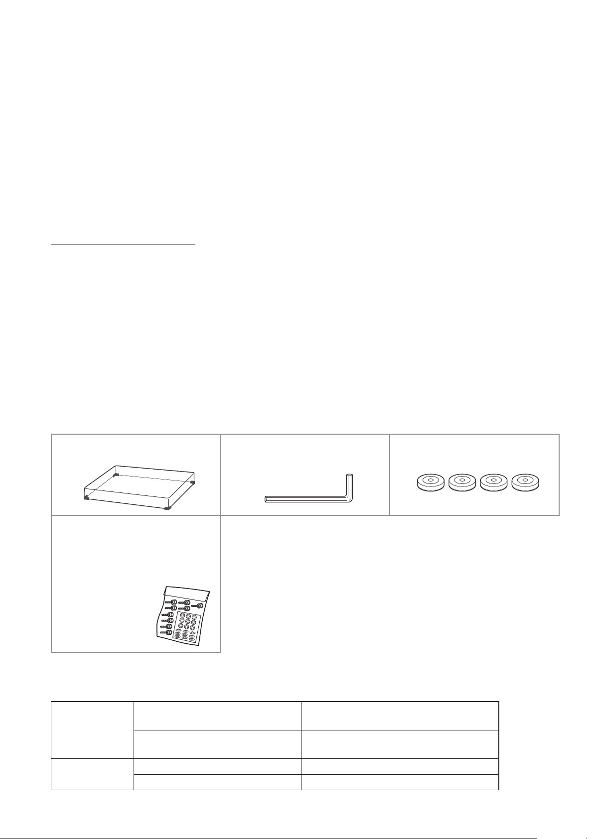
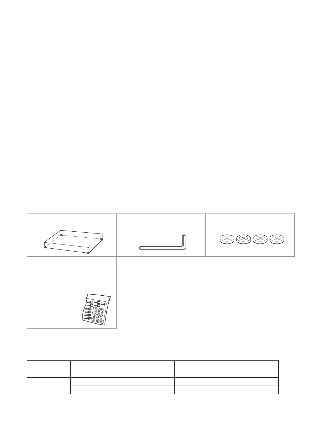
付属品
ダストカバー(1個)
(品番:TXP0046)
SP-10R取付ネジセット
(1セット)
(品番:TTV0113)
ねじ (9個)
ワッシャー (9個)
皿ばね (9個)
仕様
外形寸法
質量
六角レンチ(1個)
(品番:TTK0004)
最初に付属品を確かめてください。
包装材料などは商品を取り出したあと、保管してください。
転宅などで、遠くへ運ばれるときに必要になります。
小物部品については乳幼児の手の届かないところに適切に保管してく
ださい。
ダストカバー無し 524×97×392mm(幅×高さ×奥行)
ダストカバーあり 531×188×399mm(幅×高さ×奥行)
ダストカバー無し 約18.0kg
ダストカバーあり 約20.2kg
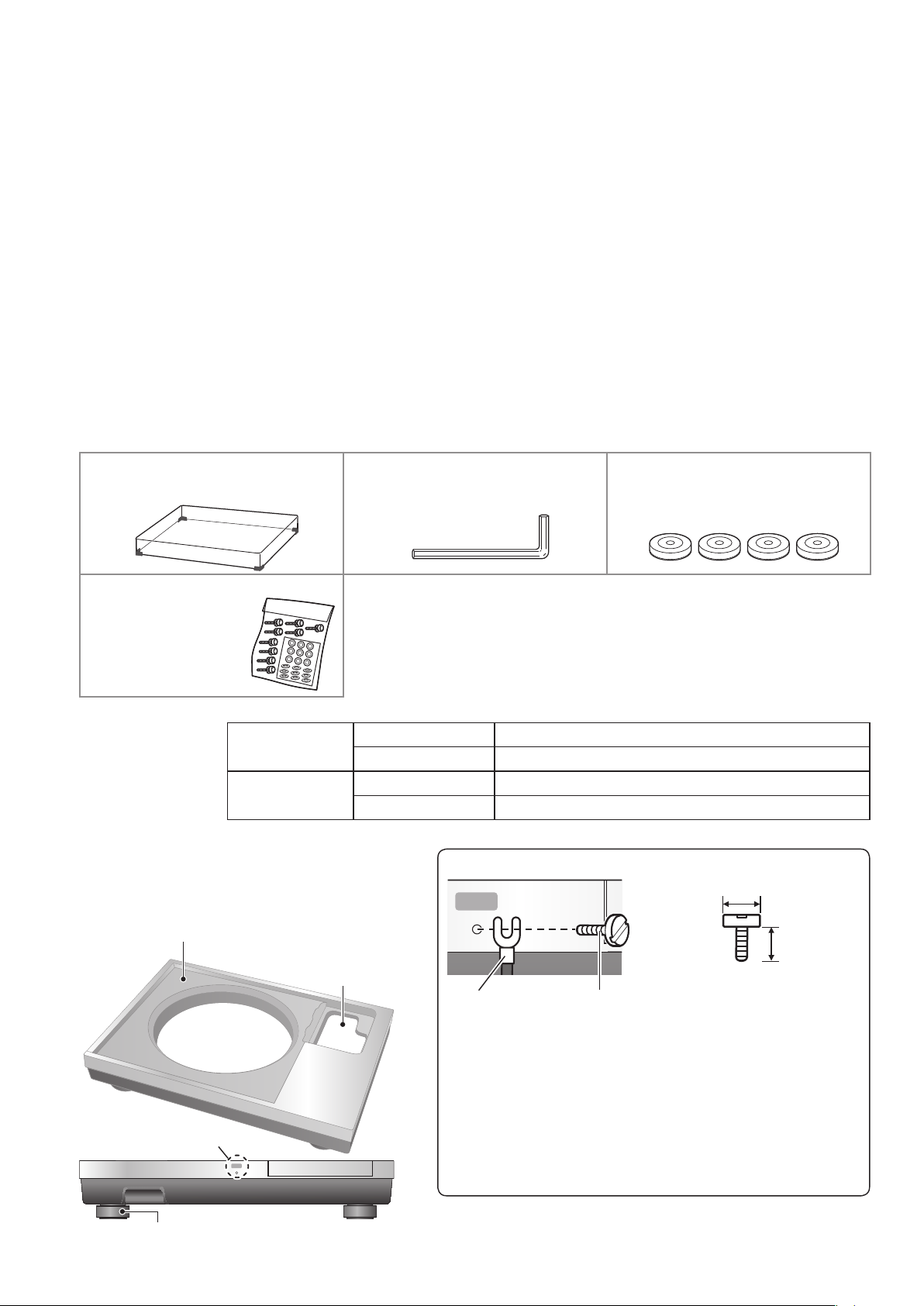
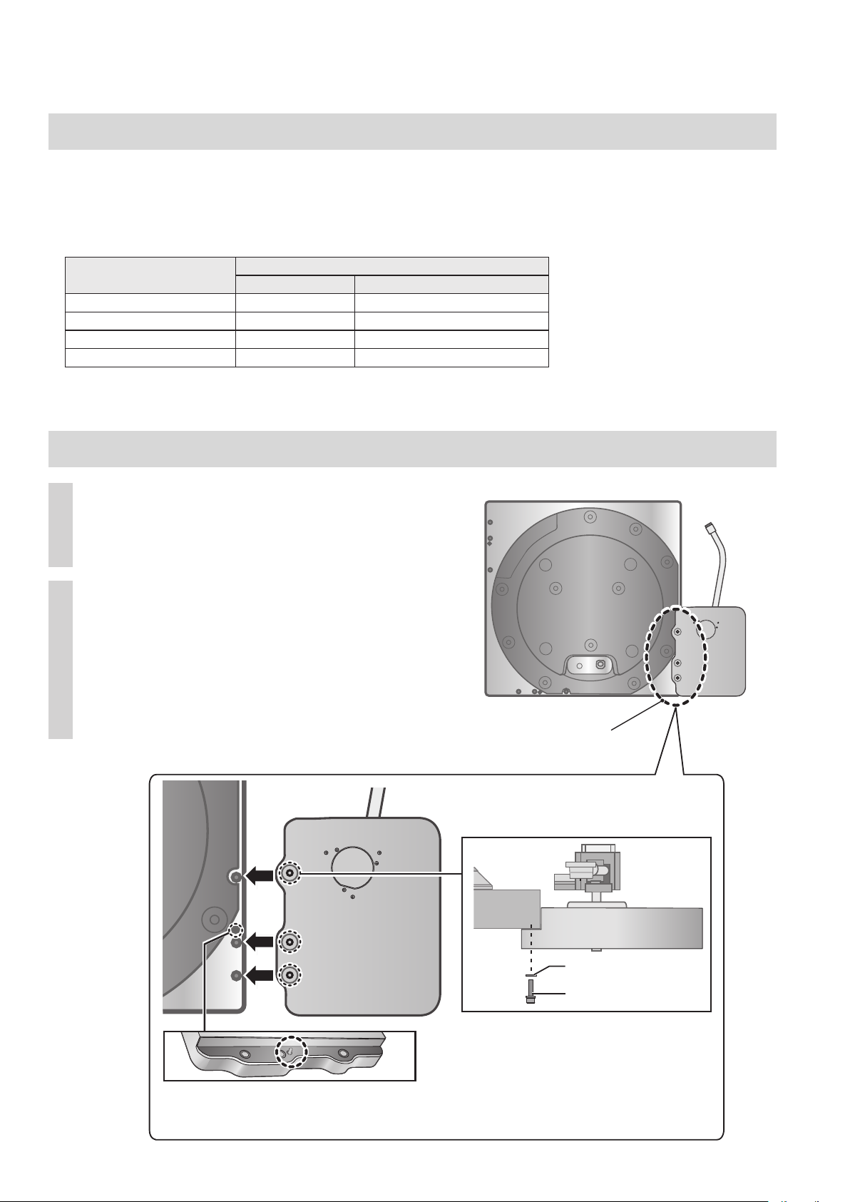
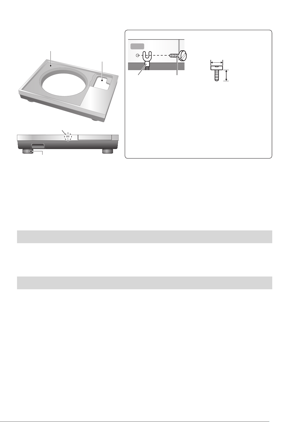
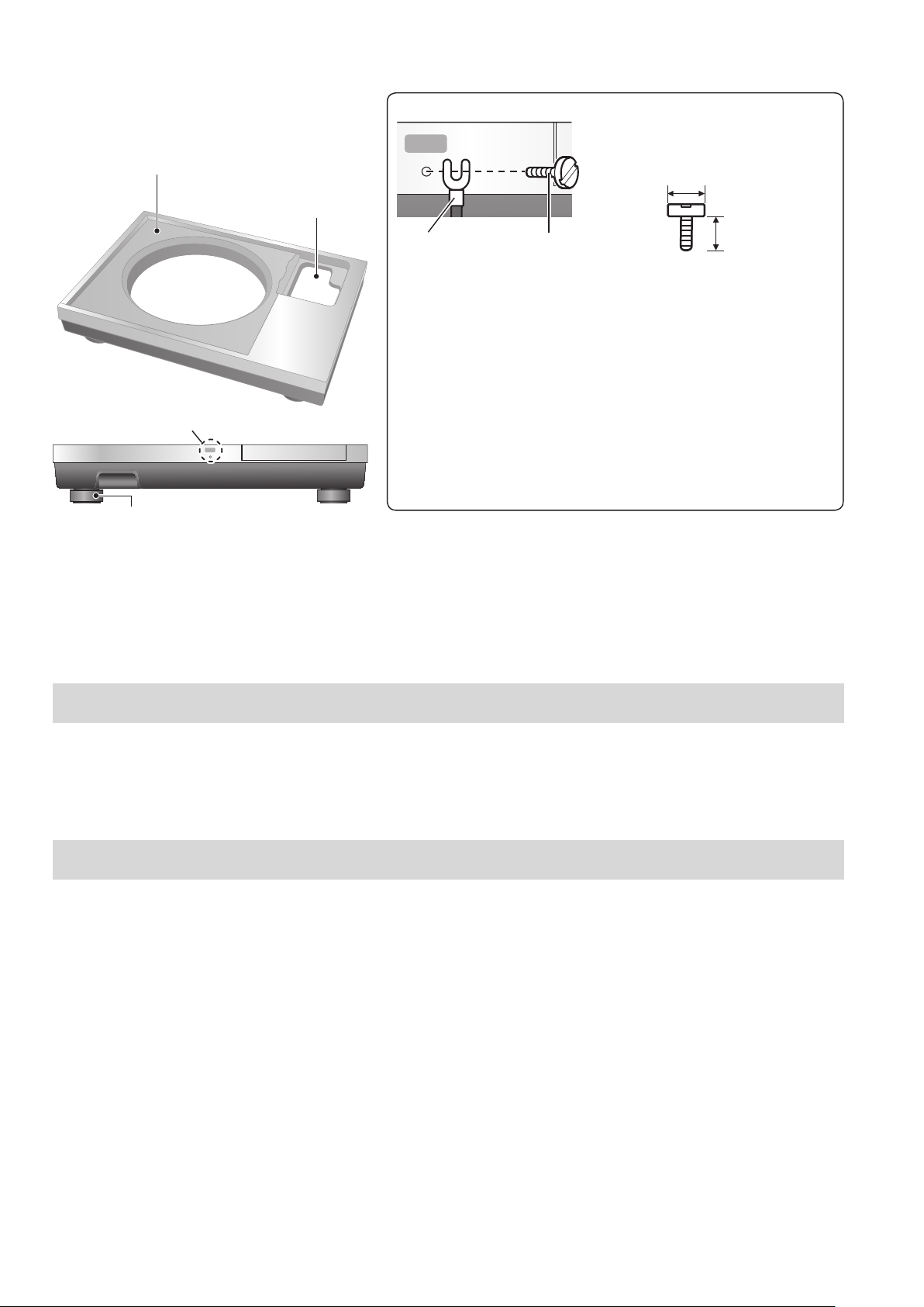
各部名称
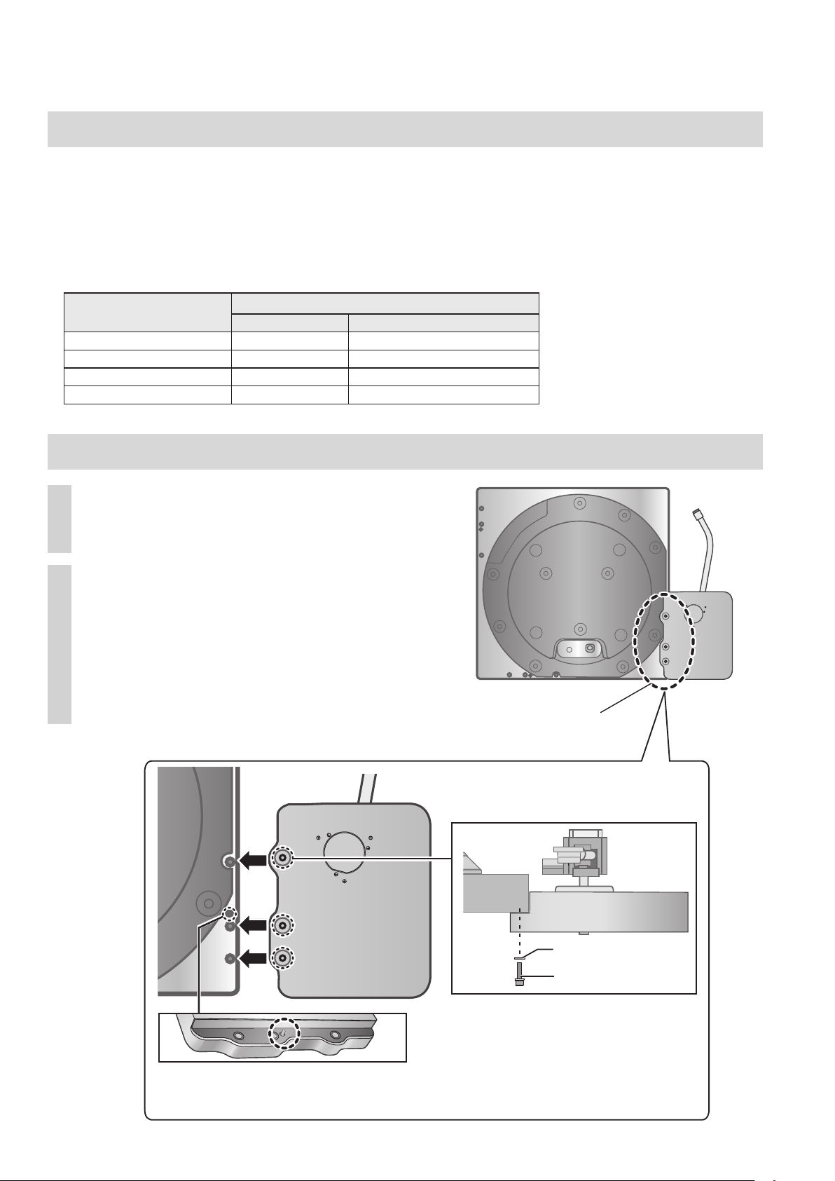
SP-10R 本体取り付け位置
SP-10R本体を取り付ける際はこの部分に絶縁物などを
貼らないでください。ノイズが発生する原因になります。
トーンアーム
ベース収納位置
※2
※1シャーシグランド
ラグ端子
アースケーブル
M3ビス
インシュレーターアタッチメント
(4個)
(品番:TEKL021)
13mm以下M3ビス
(並目)
12mm以下
シャーシグランド
インシュレーター
(2)
02
Japanese
※1
基本的にはシャーシグランドをつなぐ必要はありません。
もしノイズなどが気になる場合には下記手順で行ってください。
お使いの環境にも依存しますがノイズが減少する場合があります。
①市販のM3ビスを使用して、ラグ端子の付いたアースケーブルを
シャーシグランドに取り付けてください。
②アースケーブルをアンプのアース端子に接続してください。
●導電材質のビスをご使用ください。
※2
トーンアームベースをSP-10R本体のトーンアームベース
標準取付位置
(05)
に取り付けた場合は、ここに収納されます。
Page 3
安全上のご注意
人への危害、財産の損害を防止するため、必ずお守りいただくことを説明しています。
■誤った使い方をしたときに生じる危害や損害の程度を区分して、説明しています。
(必ずお守りください)
ǃᔎȓ⦔҈ȡ⛤ǕǙǬțǛǑȚ
⚋ܝ
■お守りいただく内容を次の図記号で説明しています。(次は図記号の例です)
ǦǵǾǓǠǹǓԑǶǨƹ ી⒅ǦǹǠțǿǹȘǹǓԑǶǨƹ
チチԑDŽǶǨƹ
小物部品は、乳幼児の手の届くところに置かない
誤って飲み込むと、身体に悪影響を及ぼします。
• 万一、飲み込んだら、すぐに医師にご相談ください。
ᗨ
ǃ⟽҈ȡ⛤ǕǢǷȓƸ⛥᧳ǽ၏્Ǜ
チチ᧯ǨȚǙǬțǛǑȚԑDŽǶǨƹ
不安定な場所に置かない
高い場所、水平以外の場所、振動や衝撃の起こる場所に置かない
倒れたり落下したりすると、けがの原因になることがあります。
本機の上に重いものを載せたり、乗ったりしない
倒れたり落下したりすると、けがの原因になることがあります。
本機の上に火のついたろうそくのような裸火を置かない
異常に温度が高くなるところに置かない
外装ケースや内部部品が劣化する原因になりますのでご注意ください。
• 直射日光の当たるところ、ストーブの近くでは特にご注意ください。
本機を持ち運ぶときは、2 人以上で行う
落下すると、けがの原因となることがあります。
ダストカバーに指をはさまれないように注意する
けがの原因になることがあります。
• 特にお子様にはご注意ください。
(3)
03
Japanese
Page 4
取り出し・準備
梱包箱からの取り出し・運搬時の注意事項
お願い
本体の取り出し、運搬は必ず2人以上で行ってください。
持ち手の位置が不適切な状態で持ち上げた場合、重心が
アンバランスにならないようにご注意ください。
・腰を痛めるおそれがあります。
・階段などでバランスを崩しけがをするおそれがあります。
取り出し時に指をはさまないように気を付けてください。
本体底面と床面のすき間に指をはさまないように気を付けて
ください。
包装材料などは商品を取り出したあと、保管しておいて
ください。転宅など遠くへ運ぶときは、開梱の逆の手順で
包装してください。
取り出す前に設置場所を決めてから作業を行ってください。
設置時の注意事項については「本体の設置」(08)を参照
ください。
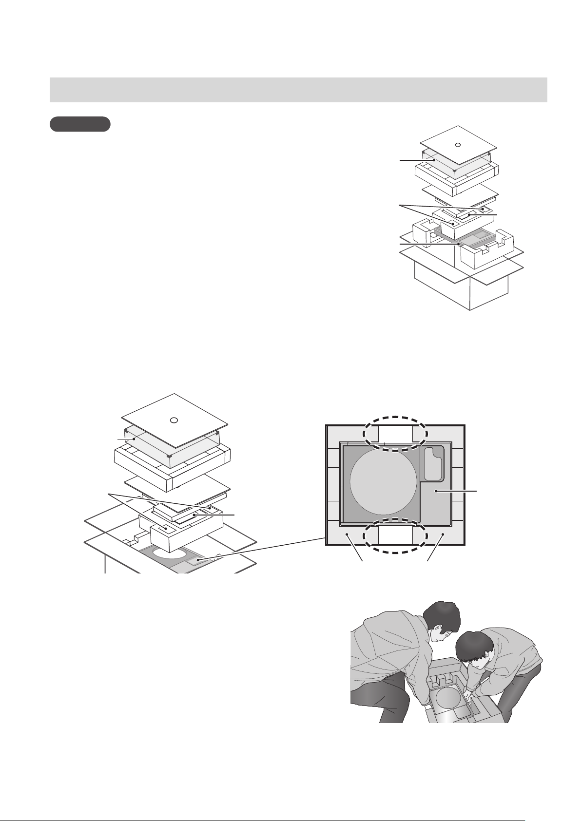
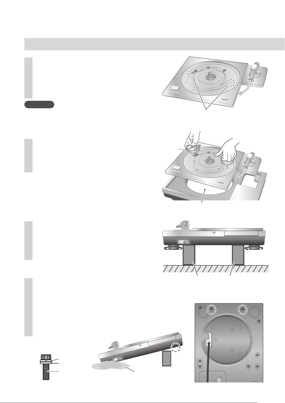
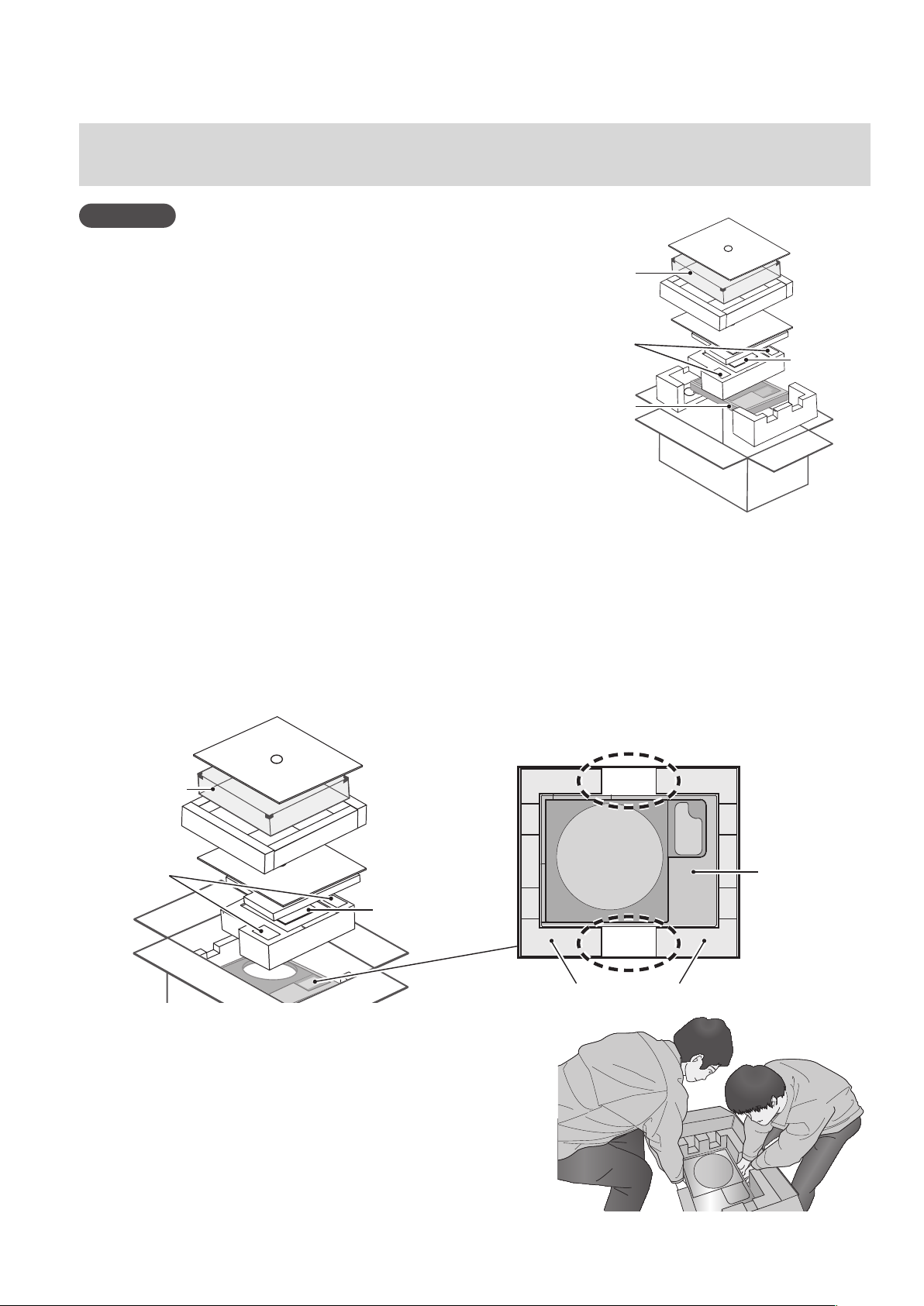
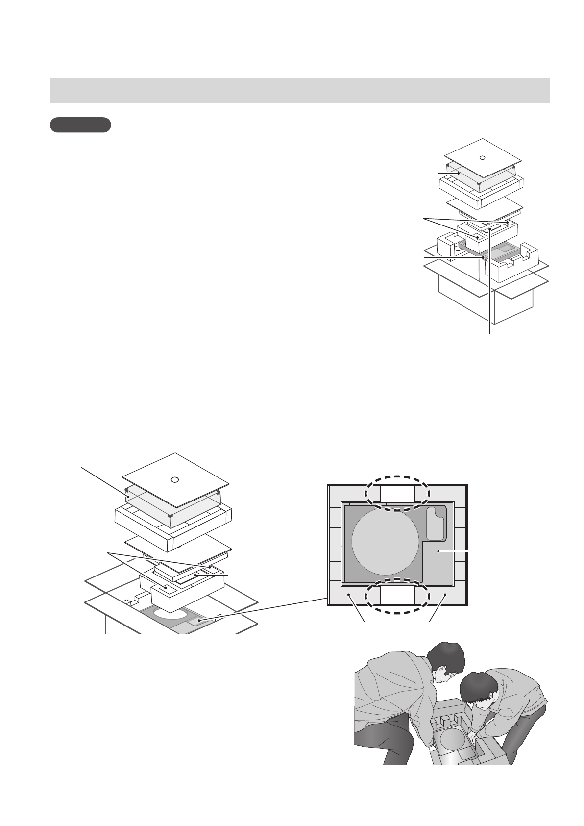
①ダストカバー、取扱説明書を取り出してください。
・付属品は乳幼児の手の届かないところへ置いてください。
・ターンテーブルベース、ダストカバーは保護シートで包まれています。
(梱包順)
ダストカバー
付属品
ターンテーブル
ベース
取扱説明書
ダストカバー
付属品
取扱説明書
②包装クッションの間(①梱包箱上面図の点線部分)に
手を入れ本体をゆっくり持ち上げて取り出してください。
取り出す作業は必ず 2 人以上で行ってください。
・
本体を持ち上げるときは十分にお気をつけください。
・手がすべらないように下側を持ってください。
・
バランスを崩さないように両手で作業してください。
梱包箱上面図
ターンテーブル
ベース
包装クッション
(4)
04
Japanese
持ち上げ作業イメージ図
Page 5
機器の組み立て
組み立てる前に
ターンテーブルの組み立て、取り外しについては別売品のSP-10Rの取扱説明書に従ってください。
トーンアームを取り付ける際は、別売品のトーンアームベース(SH-TB10)をご使用ください。
取り付けの方法など詳細は、取り付けるトーンアームの取扱説明書に従ってください。
トーンアームベース標準取付位置に取り付ける場合は、以下の品番のショートタイプをお使いください。
SH-TB10-Sを標準取付位置に取り付ける場合は設置(100)をご参照ください。
トーンアームベース
SH-TB10RT1-S ortofon AS-212S、RS-212D
SH-TB10TC1-S
SH-TB10JL1-S
SH-TB10SM1-S
トーンアームを SP-10R 本体に取り付ける
トーンアーム(ショートタイプ)
メーカー 品番
Technics EPA-100mk2
JELCO SA-250
SME M2-9R
ご使用になるトーンアームをトーンアーム
1
ベースに取り付ける。
ご使用のトーンアームの取扱説明書をご参照ください。
トーンアームベースを SP-10R 本体に取り
2
付ける。
ご使用される場所に取り付けてください。
トーンアームベースの突起部とねじ穴位置をSP-10R
本体側と合わせ、トーンアームベースに
付属している取付ねじ、ワッシャーを六角レンチで
締めこんでください(3カ所)。
トーンアームベース
標準取付位置
トーンアームベースの突起部を穴に
入れて位置調整を行ってください。
ワッシャー
ねじ
(5)
05
Japanese
Page 6

機器の組み立て
(つづき)
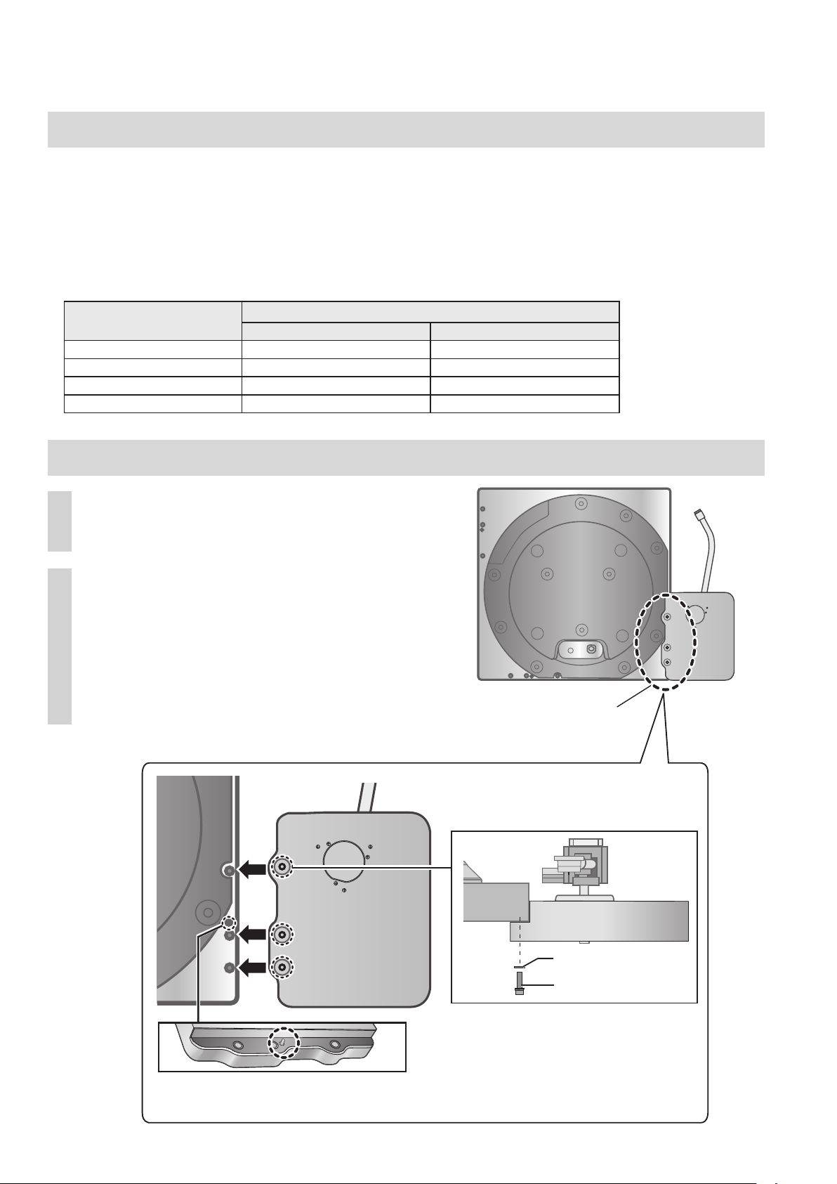
ターンテーブルベースへの取り付け
SP-10R 本体の脱着ハンドル取付穴
1
(2カ所)に SP-10R 付属の脱着ハンドル
のねじを締めこむ。
お願い
脱着ハンドルは5回転以上回して取り付けてください。
最後まで締めこんだ場合は少し戻してください。
強く締めこまないでください。
SP-10R 本体をゆっくり持ち上げ、
2
ターンテーブルベースにのせる。
コントロールユニット接続ケーブルがはさまら
ないように注意して取り付けてください。
脱着ハンドル取付穴
脱着ハンドル
インシュレーターを取り外す。
3
本体を持ち上げ、包装クッション2本を下に敷いて、
インシュレーターを下から見て反時計回り(左)の
方向に回してください。
包装クッション 1 本を敷いて本体を傾け、
4
付属品の六角レンチで SP-10R 取付ネジ
セットを取り付ける。(右図2カ所)
ねじ、ワッシャー、皿ばねは
下図の順に取り付けてください。
コントロールユニット接続ケーブルは
ターンテーブルベースの穴に通してください。
包装クッション
取り付け順
(6)
06
Japanese
皿ばね
ワッシャー
ねじ
保護シート
Page 7

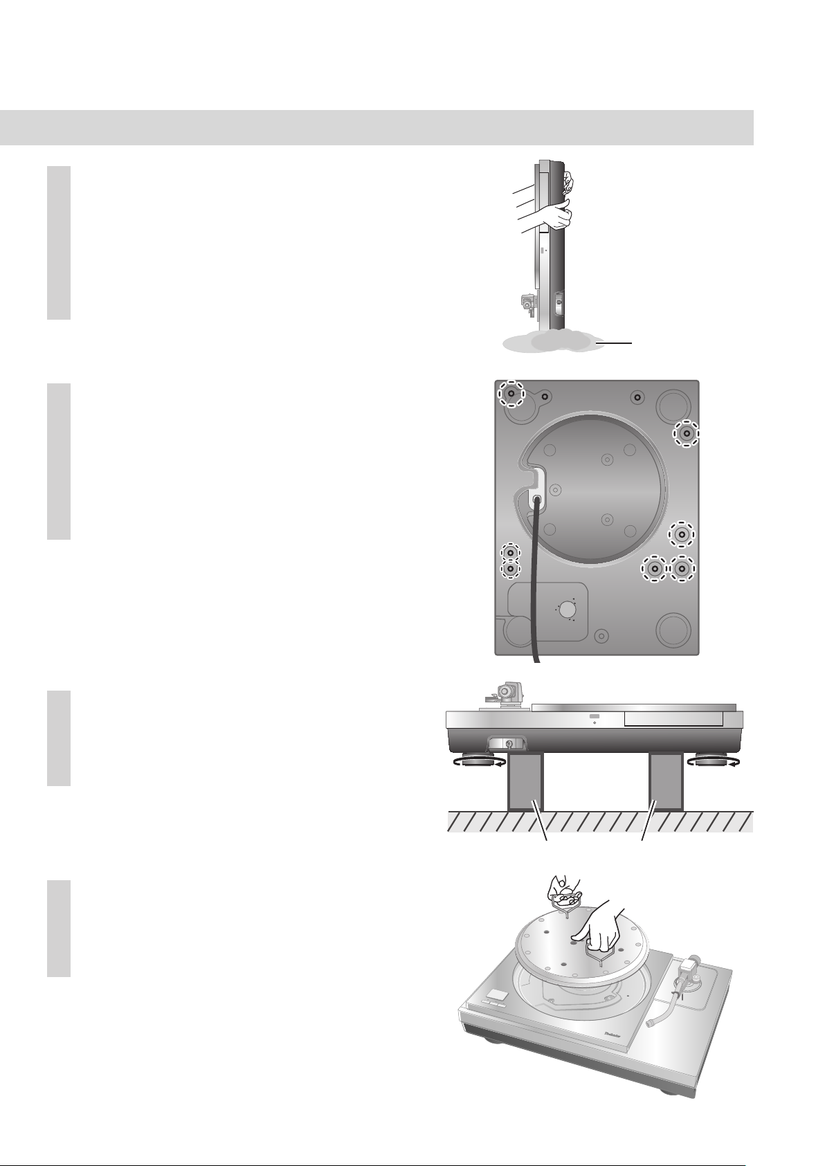
付属の保護シートの上にターンテーブル
5
ベース本体を立てる。
保護シートの下にビスなど突起物がないことを
確認してください。
バランスを崩して倒さないようにご注意ください。
付属品の六角レンチで SP-10R 取付ネジ
6
セットを取り付ける。
(右図7カ所)
手順4で取り付けた2カ所も含め、合計9カ所の
ねじがしっかり取り付けられていることを再度
確認してください。
保護シート
インシュレーターを取り付ける。
7
本体を持ち上げ、包装クッション2本を下に敷いて、
インシュレーターを下から見て時計回り(右)の方
向に回してください。
SP-10R 本体にターンテーブルを
8
取り取り付ける。
SP-10Rの取扱説明書「ターンテーブルの取り付け」
をご参照ください。
包装クッション
(7)
07
Japanese
Page 8
設 置
本体の設置
外部振動を受けにくく、安定した水平な場所に設置してください。
スピーカーシステムからできるだけ離して設置してください。
※SP-10R の取扱説明書「設置について」もご参照ください。
設置時にがたつきがある場合は、インシュレーターで調整してください。(下)
設置後は無理に引きずらないでください。インシュレーターや床面に傷がつく原因となります。
作業は必ず2人以上で行ってください。
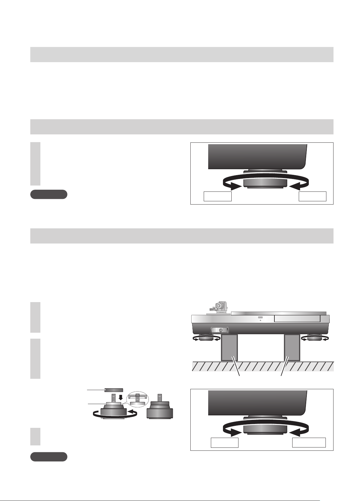
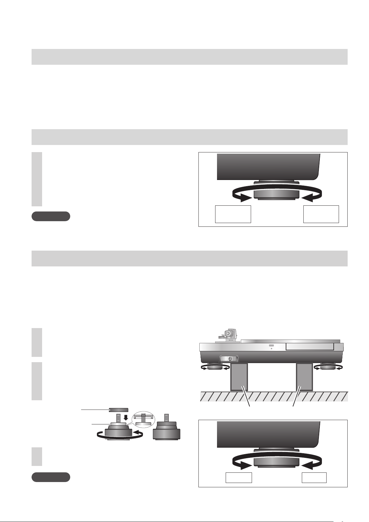
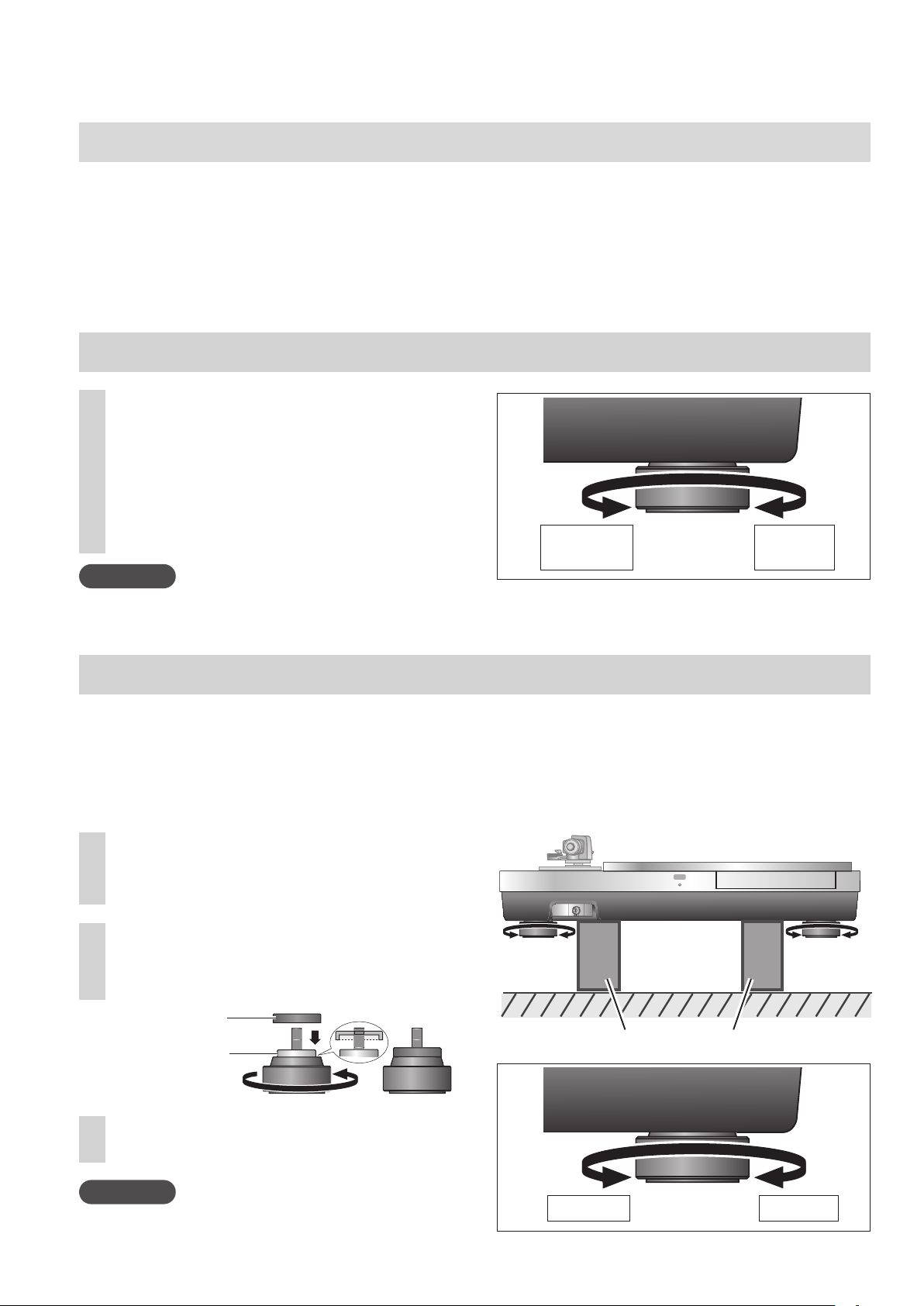
本体が水平になるように調整する
本体を持ち上げ、インシュレーターを
1
回し調整する。
下から見て、時計回り(右) :低くなる
下から見て、反時計回り(左):高くなる
お願い
インシュレーターを回しすぎないでください。
インシュレーターが外れたり、破損したりする原因となります。
高くなる
低くなる
インシュレーターアタッチメントの取り付け
インシュレーターアタッチメントは通常は取り付けない状態での使用を推奨しています。
設置環境やお客様のお好みに応じて取り付けてください。
インシュレーターアタッチメントを取り付けることにより振動吸収構造を無効化し、リジッド構造とすること
ができます。
設置環境によっては、ハウリングが発生するおそれがあります。
インシュレーターアタッチメントを取り付けた場合、ハウリングが発生するおそれがあります。
インシュレーターを取り外す。
1
包装クッションを本機の下に敷くなどして作業
を行ってください。
インシュレーターアタッチメントを
2
インシュレーターに取り付ける。
インシュレーターのクッション機能をなくし
ます。
包装クッション
インシュレーター
アタッチメント
クッション
インシュレーターを取り付ける。
3
お願い
バランスを崩さないように注意ください。
(8)
08
Japanese
取り外す
取り付ける
Page 9
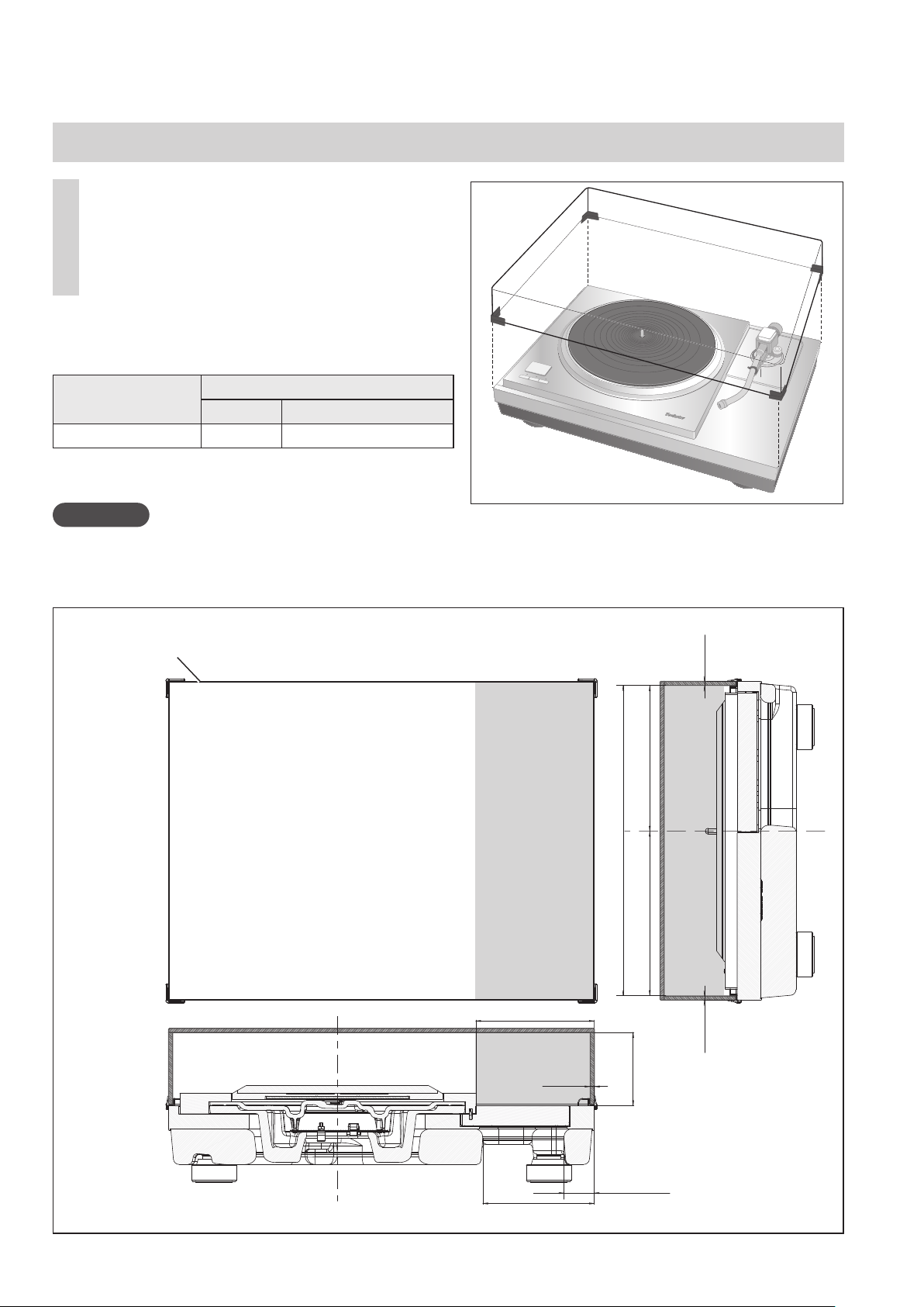
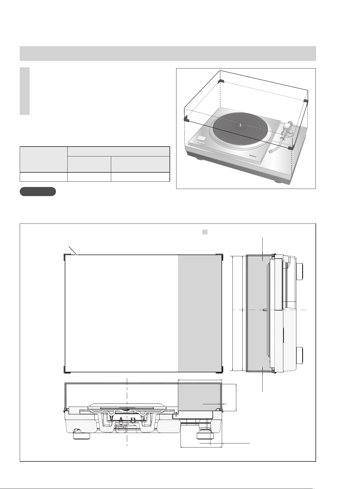
ダストカバーの取り付け
両側を支えて、ダストカバーの4角を
1
本体の4角に合わせて置く。
外す場合は、ダストカバーを真上に引き上げ
てください。
以下の組み合わせでトーンアームベースとトーンアーム
を取り付けている時はダストカバーが干渉します。
ダストカバーを取り付けないでください。
トーンアームベース
SH-TB10JL1-S JELCO SA-250
お願い
サブアームを接続している場合はダストカバーを使用しないでください。
演奏中はダストカバーを取り付けないでください。
トーンアーム(ショートタイプ)
メーカー 品番
■ ダストカバー取り付け時のすき間寸法(■:すき間)
ダストカバー
5 mm
145.7 mm
5 mm
137.2 mm
381.9 mm
202.7 mm 179.2 mm
90 mm
37.4 mm
5 mm
(9)
09
Japanese
Page 10
保証とアフターサービス
使いかた・お手入れ・修理などは、まず、お買い求め先へご相談ください
▼ お買い上げの際に記入されると便利です
販売店名
電 話 ( ) −
お買い上げ日 年 月 日
●保証期間中は、保証書の規定に従って出張修理
いたします。
保証期間:お買い上げ日から本体 1 年間
●保証期間終了後は、診断をして修理できる場合は
ご要望により修理させていただきます。
※修理料金は次の内容で構成されています。
技術料
部品代
出張料
診断・修理・調整・点検などの費用
部品および補助材料代
技術者を派遣する費用
転居や贈答品などでお困りの場合は、次の窓口にご相談ください
修理を依頼されるときは
お買い上げ日と下の内容をご連絡ください。
●製品名 ターンテーブルベース
●品 番 SH-1000R
●故障の状況 できるだけ具体的に
※補修用性能部品の保有期間
当社は、このターンテーブルベースの補修用性能
部品(製品の機能を維持するための部品)を、製造
打ち切り後8年保有しています。
8年
ご相談窓口におけるお客様の個人情報のお取り扱いについて
パナソニック株式会社およびグループ関係会社は、お客様の個人情報をご相談対応や修理対応などに利用させていただき、
ご相談内容は録音させていただきます。また、折り返し電話をさせていただくときのために発信番号を通知いただいてお
ります。なお、個人情報を適切に管理し、修理業務等を委託する場合や正当な理由がある場合を除き、第三者に開示・提
供いたしません。個人情報に関するお問い合わせは、ご相談いただきました窓口にご連絡ください。
パナソニック
特典
●
保証書用封筒に記載されている
QR コードから登録していただくと、
品番登録と製造番号を入力する必要がなく、
簡単に登録いただけます。
(10)
10
の会員サイト
●お宅の家電商品、消耗品情報が一元管理できる!
●
登録商品に関するお知らせやサポート情報が入手できる!
●登録すると抽選で商品券などが当たる!
Ẑ
CLUBPanasonic
QR コード
QR コードは、株式会社デンソーウェーブの登録商標です。
で
Ẑご愛用者登録ẑ
ẑ
詳しくはこちら
http://club.panasonic.jp/aiyo/
をお願いします
Japanese
Page 11

(11)
11
Japanese
Page 12

Introduction
Thank you for purchasing this product.
This product is a special turntable base for SP-10R. Please read these instructions carefully before
using this product, and save this manual for future use.
Features
Thorough anti-vibration designed cabinet and insulator
The high-rigidity cabinet is composed of different types materials such as aluminum and BMC.
Silicon rubber with high damping characteristics and excellent long-term reliability is used in the
insulator to shut out external vibration.
For the U.S.A. and Canada
If you have any questions, visit:
U.S.A.: http://shop.panasonic.com/support
Canada: www.panasonic.ca/english/support
Register online at
http://shop.panasonic.com/support (U.S. customers only)
For the United Kingdom and Ireland customers
Sales and Support Information
Customer Communications Centre
For customers within the UK: 0333 222 8777
For customers within Ireland: 01 447 5229
Monday–Friday 9:00 am – 5:00 pm,
(Excluding public holidays).
For further support on your product, please visit our website:
www.technics.com/uk/
Table of contents
Accessories ..................................................................................................................... 02
Specifications .................................................................................................................02
Parts Name .....................................................................................................................03
Safety precautions .......................................................................................................... 03
Unpacking and preparation ............................................................................................04
Putting the player together ............................................................................................. 05
Installation .............................................................................................................. 08, 100
Accessories
Dust cover (1 pc.)
(TXP0046)
Hex wrench (1 pc.)
(TTK0004)
Insulator attachment (4 pc.)
(TEKL021)
Screw set for SP-10R
(1 set)(TTV0113)
Screws (9 pc.)
Washers (9 pc.)
Belleville springs (9 pc.)
Specifications
Main unit without dustcover 524×97×392 mm (W×H×D)
Dimensions
Mass
(12)
02
English
Main unit with dustcover 531×188×399 mm (W×H×D)
Main unit without dustcover Approx. 18.0 k
Main unit with dustcover Approx. 20.2 k
Please check and identify the supplied accessories.
Keep the packaging materials after taking out the goods.
You will need them when carrying the product for a long
distance.
Keep screws, washers and belleville springs out of reach of
children to prevent swallowing.
(20-21/32 × 6-13/16 × 15-7/16 inch)
(20-29/32 × 7-13/32 × 15-23/32 inch)
g
g
Page 13

Parts Name
Position for mounting the SP-10R main unit
Do not attach insulators here when
mounting the SP-10R main unit.
Doing so may result in noise.
Position for storing
the tonearm base
Chassis ground*
Insulator
1
*1Chassis ground
M3 screw
(Coarse thread)
13 mm or less
2
*
Earth lead
with lug
Basically, there is no need to connect the chassis
ground.
If you are concerned about the noise, connect as
described below. The noise may decrease though it
depends on your environment of use.
Using a commercially available M3 screw, attach an
earth lead with lug to the chassis ground.
Connect the earth lead to the earth terminal on the
amplifier.
Use a conductive screw.
●
The tonearm base that is mounted on the standard position
*2
(
05) for mounting the tonearm base on the SP-10R main
unit can be stored here.
M3 screw
12 mm or less
Safety precautions
Warning
Do not put small parts within the reach of small children.
Accidental swallowing of such an item has a harmful effect on the body.
- In the event that such an item has been swallowed, consult a doctor immediately.
Caution
Place this unit on an even surface.
Do not install the product at a high place, uneven place, or place with vibration or impact.
-The product may turn over or fall, resulting in injury.
Do not put a heavy thing on the product or do not step on the product.
-The product may turn over or fall, resulting in injury.
Do not place sources of naked flames, such as lighted candles, on this unit.
Do not install the product in an extremely high temperature.
The outer case and internal parts may be deteriorated.
-Observe the temperature if the product is exposed to direct sunlight or installed near a heater.
Always use two people or more to install or move the unit
- Doing so may cause this unit to fall, resulting in personal injury or malfunction of this unit.
Be careful not to have your fingers caught by the dust cover.
Otherwise your fingers may be injured.
-Particularly keep an eye on a child.
.
(13)
03
English
Page 14

Unpacking and preparation
Notes for taking out the goods from the package box and transporting
Attention
Always use two or more people to take out and
transport the main unit.
Be careful not to lose balance if lifting the unit with
your hands at non-optimal position.
You may damage your back.
・
You may lose balance on the stairs and the like,
・
which may lead to injury.
Be careful not to catch your fingers when taking out
the main unit.
Be careful not to catch your fingers in the gap between
the bottom of the main unit and floor.
Keep the packaging materials after taking out the goods.
Pack the product in the reverse order of unpacking
before carrying it to a far place, for example when
moving to another house.
Take out the goods after deciding the installation
location.
For notes regarding installation, see “Installation” (08).
Take out the dust cover and operating instructions.
Keep accessories out children’s reach.
The turntable base and dust cover are wrapped in protective sheets.
Packing order
Dust cover
Accessories
Turntable
Base
Operating
Instructions
Dust cover
Accessories
Operating
Instructions
Put your hands between the packing cushions
(dotted line area of the package box top view) and
slowly lift the main unit to take it out.
Always perform this task using two or more people.
• Be very careful when lifting the main unit.
• Hold the main unit from the bottom toprevent it
from slipping from your hands.
• Perform the task using both hands to not lose
balance.
Package box top view
Turntable
Base
Packing cushion
(14)
04
English
Lifting task image
Page 15
Putting the player together
Before putting the player together
For how to assemble or remove the turntable, see the SP-10R operating instructions.
Use the tonearm base (SH-TB10) sold separately when mounting a tone arm. For details on how to
mount, see the operating instructions of the tone arm to be mounted.
Select a short-type tonearm base from the model numbers listed below when mounting it on the
standard position for mounting the tonearm base.
To mount SH-TB10-S on the standard position for mounting the tonearm base, see the section of
installation (100).
Tonearm base
SH-TB10RT1-S ortofon AS-212S, RS-212D
SH-TB10TC1-S Technics EPA-100mk2
SH-TB10JL1-S JELCO SA-250
SH-TB10SM1-S SME M2-9R
Manufacturer Model number
Tone arm (Short-type)
Mount the tone arm on the SP-10R main unit
Mount your tone arm to
1
the tonearm base.
Refer to your tone arm leaflet.
Mount the tonearm base on the
2
SP-10R main unit.
Mount in the appropriate location.
Fit the projections and screw holes of the
tonearm base in the SP-10R main unit
and tighten it (at three locations) with the
mounting screws and washers supplied with
the tonearm base using the hex wrench.
Standard position
for mounting the
tonearm base
Insert the pin on the tonearm base into
the pin hole to position.
Washer
Screw
(15)
05
English
Page 16
Putting the player together
Mounting on the turntable base
Tighten the detachable handle
1
screws supplied with SP-10R into the
detachable handle mounting holes
(at two locations) on the SP-10R
main unit.
Attention
(continued)
Tighten the detachable handle by turning it 5 or
more times. If you have tightened it until the end,
loose a little bit. Do not tighten it firmly.
Slowly lift the SP-10R main unit and
2
place it on the turntable base.
Be careful not to catch the control unit
connection cable.
Remove the insulators.
3
Place two packing cushions under the main
unit to lift it, and turn the insulators counterclockwise (to the left hand) when seen from
below.
Detachable handle
mounting hole
Detachable
handle
Pass the control unit connection cable
through the hole on the turntable base.
Place one packing cushion under the
4
main unit to put it at an angle to
tighten the screw set for SP-10R using
the accessory hex wrench.
(The two locations indicated in the
figure right)
Attach the screw, washer and belleville spring
in the order as shown below.
The attaching order
Belleville
springs
Washers
Screws
(16)
06
English
Packing cushion
Protective sheets
Page 17
Put the main unit vertically on a side
5
on the protective sheet that came
with the main unit.
Make sure there are no protruding objects,
such as screws, under the protective sheet.
Be careful the main unit does not lose
balance and tip over.
Tighten the screw set for SP-10R
6
using the accessory hex wrench.
(The seven locations indicated in the
figure right)
Check that all nine screws including the
two tightened in step 4 have been firmly
tightened.
Protective sheets
Attach the insulators to the unit.
7
Place two packing cushions under the main
unit to lift it, and turn the insulators clockwise
(to the right hand) when seen from below.
Mount the turntable on the SP-10R
8
main unit.
See “Fitting the turntable” in the SP-10R
operating instructions.
Packing cushion
(17)
07
English
Page 18
Installation
Installation
Install the unit on a horizontal surface protected from vibrations.
Keep this unit as far as possible from speakers.
*See “Notes for installation” as well in the SP-10R operating instructions.
If the unit rattles when installed, adjust by inserting insulators. (below)
Do not draw the unit forcibly after installation. Doing so may damage the insulator or floor surface.
Always use two people or more to perform the task.
Adjusting the height to make the unit horizontal
Raise the main unit to turn the
1
insulators and adjust the height.
Clockwise (to the right hand) when seen
from below: Lowered
Counter-clockwise (to the left hand)
when seen from below: Raised
Attention
Do not turn the insulators too far.
Doing so may cause them to come off or damage them.
Increases
the height
Reduces
the height
Insulator attachment
It is recommended that the unit be used without the insulator attachments normally.
Use the insulator attachments according to the installation environments or your preference.
Vibration absorption is disabled and the structure becomes rigid when the insulator attachments
are attached.
Howling may occur in some installation environments.
Howling may occur as a result of attaching insulator attachments.
Remove the insulators.
1
Perform the task by placing the packing
cushion or the like under the unit.
Attach the insulator attachment
2
by screwing it on the insulator.
This makes the insulator lose its
cushioning function.
Insulator
attachment
Cushion
Attach the insulators.
3
Attention
Be careful not to lose balance.
(18)
08
English
Packing cushion
Detach
Attach
Page 19

Fit the dust cover
While holding the dust cover
1
from both sides, put it in place by
aligning its four corners with the
four corners of the unit.
When removing, lift the dust cover
straight up.
The combination of the following tonearm base
and tone arm will cause interference with the dust
cover. Therefore, remove the dust cover.
Tonearm base
SH-TB10JL1-S JELCO SA-250
Attention
Do not use the dust cover if you have a second tone arm connected.
Remove the dust cover while playing.
Clearance for installing the dust cover ( : Clearance)
Dust cover
Manufacturer Model number
Tone arm (Short-type)
5 mm
381.9 mm
145.7 mm
5 mm
137.2 mm
202.7 mm 179.2 mm
90 mm
37.4 mm
5 mm
(19)
09
English
Page 20
Introduction
Nous vous remercions d’avoir arrêté votre choix sur cet appareil.
Ce produit est une base de platine spéciale pour le SP-10R. Veuillez lire attentivement ces instructions
avant d’utiliser ce produit et conservez ce manuel pour une utilisation future.
Caractéristiques
Coffret et isolateur à conception anti-vibration totale
Le coffret à cinq couches haute rigidité est composé de divers types de matériaux tels que
l'aluminium et le mélange à moule en vrac (BMC).
Le caoutchouc à la silicone avec capacités d'amortissement élevées et une excellente fiabilité à long
terme est utilisé dans l'isolateur pour amortir les vibrations externes.
Pour toute assistance supplémentaire, visitez :
États-Unis : http://shop.panasonic.com/support
Canada : www.panasonic.ca/french/support
Inscrivez-vous en ligne sur le site :
http://shop.panasonic.com/support (clients situés aux États-Unis uniquement)
Table des matières
Accessoires ..................................................................................................................... 02
Spécifications .................................................................................................................02
Nom des pièces ..............................................................................................................03
Précautions de sécurité ................................................................................................... 03
Déballage et préparatifs. ................................................................................................. 04
Assemblage du tourne-disque ......................................................................................... 05
Installation .............................................................................................................. 08, 100
Accessoires
Couvercle (1 pc.)
(TXP0046)
Ensemble de vis pour SP-10R
(1 jeu)(TTV0113)
Vis (9 pc.)
Rondelles (9 pc.)
Ressorts Belleville (9 pc.)
Spécifications
Clé hexagonale (1 pc.)
(TTK0004)
Vérifiez la présence et l’état des pièces et accessoires suivants.
Conservez les matériaux d’emballage après avoir sorti les
marchandises.
Vous en aurez besoin lors du transport du produit sur une
longue distance.
Gardez les vis, les rondelles et les ressorts Belleville hors de
portée des enfants pour éviter toute ingestion.
Accessoire isolant (4 pc.)
(TEKL021)
Unité principale sans couvercle 524×97×392 mm (L×H×P)
Dimensions
Poids
(20)
02
Unité principale avec couvercle 531×188×399 mm (L×H×P)
Unité principale sans couvercle Environ 18,0 k
Unité principale avec couvercle Environ 20,2 k
Français (Canada)
(20-21/32 × 6-13/16 × 15-7/16 po)
(20-29/32 × 7-13/32 × 15-23/32 po)
g
g
Page 21
Nom des pièces
Position de montage de l’unité principale SP-10R
Ne fixez pas d’isolateurs ici lors du montage
de l’unité principale SP-10R. Cela pourrait
causer du bruit.
Position pour la base du
bras de lecture
Masse du châssis*
Isolant
1
2
*
*1Masse du châssis
Vis M3
(gros fil)
13 mm ou moins
Fil de terre
avec cosse
Il n’est pas fondamentalement nécessaire de connecter
la masse du châssis. Si vous êtes préoccupé par le
bruit, connectez comme décrit ci-dessous. Le bruit peut
diminuer mais cela dépend de votre environnement
d’utilisation.
À l’aide d’une vis M3 disponible dans le commerce,
fixez le fil de terre avec cosse à la masse du châssis.
Connectez le fil de terre à la borne de mise à la terre
sur l’amplificateur.
Utilisez une vis conductrice.
La base du bras de lecture montée à la position standard
*2
(
05) pour le montage de la base du bras de lecture sur
l’unité principale SP-10R peut être placée ici.
Vis M3
12 mm ou moins
Précautions de sécurité
Avertissement
Ne mettez pas de petites pièces à la portée des jeunes enfants.
L’ingestion accidentelle d’un tel produit a un effet néfaste sur le corps.
- En cas d’ingestion d’un tel produit, consultez immédiatement un médecin.
Attention
Placez cette unité sur une surface plane.
N’installez pas le produit dans un endroit élevé, inégal ou soumis à des vibrations ou à des impacts.
-Le produit risque de se retourner ou de tomber, entraînant des blessures.
Ne posez pas d’objet lourd sur le produit et ne marchez pas dessus.
-Le produit risque de se retourner ou de tomber, entraînant des blessures.
Ne placez sur l’appareil aucune source de flamme nue, telles des bougies allumées.
N’installez pas le produit à une température extrêmement élevée.
Le boîtier et les pièces internes peuvent être détériorés.
-En particulier, ne l’exposez pas aux rayons directs du soleil et ne l’installez pas près d’un appareil
de chauffage.
Soyez toujours au moins deux personnes pour installer et transporter l’unité principale.
-Sinon, l’appareil pourrait tomber et causer des blessures ou un dysfonctionnement.
Veillez à ne pas vous coincer les doigts dans le couvercle.
Sinon, vos doigts pourraient être blessés.
-Surveillez particulièrement les enfants.
(21)
03
Français (Canada)
Page 22
Déballage et préparatifs
Remarques pour sortir les marchandises de la boîte
et les transporter
Attention
Soyez toujours au moins deux personnes pour sortir et
transporter l’unité principale.
Veillez à ne pas perdre l’équilibre si vous soulevez
l’appareil avec vos mains à une position non optimale.
Vous pourriez vous faire mal au dos.
・
Vous pourriez perdre l’équilibre dans les escaliers ou
・
autre, ce qui pourrait entraîner des blessures.
Veillez à ne pas vous coincer les doigts lorsque vous
sortez l’unité principale.
Veillez à ne pas vous coincer les doigts dans l’espace
entre le bas de l’unité principale et le sol.
Conservez les matériaux d’emballage après avoir sorti
les marchandises. Emballez le produit dans l’ordre
inverse du déballage avant de le transporter dans un
endroit éloigné, par exemple lors d’un déménagement
dans une autre maison.
Sortez les marchandises après avoir décidé de
l’emplacement d’installation.
Pour les remarques concernant l’installation,
consultez la section « Installation » (08).
Retirez le couvercle et le manuel d’utilisation.
Tenez les accessoires hors de portée des enfants.
La base de platine et le couvercle sont enveloppés dans des feuilles de protection.
Ordre pour l’emballage
Couvercle
Accessoires
Base de
platine
Manuel
d’utilisation
Couvercle
Accessoires
Manuel
d’utilisation
Placez vos mains entre les coussins d’emballage
(zone en pointillés de la vue supérieure de la boîte)
et soulevez lentement l’unité principale pour la
retirer. Soyez toujours au moins deux personnes pour
effectuer cette tâche.
• Soyez très prudent lorsque vous soulevez l’unité
principale.
• Tenez l’unité principale par le bas pour l’empêcher
de glisser de vos mains.
• Effectuez la tâche avec les deux mains pour ne pas
perdre l’équilibre.
(22)
04
Français (Canada)
Vue supérieure de la boîte
Base de
platine
Coussin d’emballage
Image de la tâche de soulèvement
Page 23
Assemblage du tourne-disque
Avant d’assembler le tourne-disque
Pour savoir comment assembler ou retirer le plateau, consultez le manuel d’utilisation du SP-10R.
Utilisez la base du bras de lecture (SH-TB10), vendue séparément, lors du montage d’un bras de
lecture. Pour en savoir plus sur le montage, consultez le manuel d’utilisation du bras de lecture à
monter.
Sélectionnez une base de bras de lecture court parmi les numéros de modèle indiqués ci-dessous
lors du montage en position standard pour le montage de la base du bras de lecture.
Pour monter le SH-TB10-S à la position standard pour le montage de la base du bras de lecture,
consultez la section Installation (100).
Base de bras de lecture
SH-TB10RT1-S ortofon AS-212S, RS-212D
SH-TB10TC1-S Technics EPA-100mk2
SH-TB10JL1-S JELCO SA-250
SH-TB10SM1-S SME M2-9R
Fabricant pris en charge
Bras de lecture (Court)
Numéro de modèle
Montage du bras de lecture sur l’unité principale SP-10R
Montez votre bras de lecture sur la
1
base du bras de lecture.
Consultez votre feuillet sur le bras de lecture.
Montez la base du bras de lecture sur
2
l’unité principale SP-10R.
Montez à l’endroit approprié.
Alignez les trous de vis de la base de bras de
lecture sur les saillies dans l’unité principale
SP-10R et fixez (à trois endroits) avec les vis de
montage et les rondelles fournies avec la base
de bras de lecture à l’aide de la clé hexagonale.
Position standard pour
le montage de la base
de bras de lecture.
Insérez la goupille de la base du bras de lecture
dans le trou de goupille pour le positionner.
Rondelles
Vis
Français (Canada)
(23)
05
Page 24

Assemblage du tourne-disque
Montage sur la base de platine
Serrez les vis des poignées
1
détachables fournies avec le SP-10R
dans les trous de montage des
poignées détachables (à deux
emplacements) sur l’unité principale
SP-10R.
Attention
Serrez les poignées détachables en les tournant au
moins 5 fois. Si vous les avez serrées jusqu’au bout,
desserrez-les un peu. Ne les serrez pas à fond.
(suite)
Trous de montage des
poignées détachables
Soulevez lentement l’unité
2
principale SP-10R et placez-la sur la
base de platine.
Veillez à ne pas coincer le câble de
connexion de l’unité de commande.
Enlevez les isolateurs.
3
Placez deux coussins d’emballage sous l’unité
principale pour la soulever et tournez les
isolateurs dans le sens anti-horaire (vers la
gauche) vue du dessous.
Placez un coussin d’emballage sous
4
l’unité principale pour la placer
dans un certain angle afin de serrer
l’ensemble de vis pour le SP-10R à
l’aide de la clé hexagonale fournie.
(Les deux emplacements sont
indiqués dans la figure à droite.)
Fixez la vis, la rondelle et le ressort Belleville
dans l’ordre indiqué ci-dessous.
Poignée
détachable
Faites passer le câble de connexion de l’unité de
commande à travers l’orifice de la base de platine.
Coussin d’emballage
Ordre de fixation.
Ressorts
Belleville
Rondelles
Vis
(24)
06
Français (Canada)
Feuille de protection
Page 25

Placez l’unité principale à la
5
verticale sur un côté sur la feuille
de protection fournie avec l’unité
principale.
Assurez-vous qu’il n’y a pas d’objets en
saillie, tels que des vis, sous la feuille de
protection.
Veillez à ce que l’unité principale ne perde
pas l’équilibre et ne bascule pas.
Serrez l’ensemble de vis pour le
6
SP-10R à l’aide de la clé hexagonale
fournie.
(Les sept emplacements sont indiqués
dans la figure à droite.)
Vérifiez que les neuf vis, y compris les deux
serrées à l’étape 4, ont été bien serrées.
Feuille de protection
Fixez les isolateurs à l’unité.
7
Placez deux coussins d’emballage sous l’unité
principale pour la soulever et tournez les
isolateurs dans le sens horaire (vers la droite)
vue du dessous.
Montez le plateau sur l’unité
8
principale du SP-10R.
Consultez « Montage du plateau » dans le
manuel d’utilisation du SP-10R.
Coussin d’emballage
(25)
07
Français (Canada)
Page 26
Installation
Installation
Installez le tourne-disque sur une surface de niveau, à l’abri de toute vibration.
Éloignez le tourne-disque le plus loin possible des enceintes.
*Consultez « Remarques pour l’installation » également dans le manuel d’utilisation du SP-10R.
Si l’unité vibre lorsqu’elle est installée, réglez-la en insérant des isolateurs (ci-dessous).
Ne tirez pas l’unité avec force après l’installation. Cela pourrait endommager les isolateurs ou la
surface du sol.
Soyez toujours aux moins deux personnes pour effectuer cette tâche.
Réglage de la hauteur pour mettre le tourne-disque au niveau
Soulevez le tourne-disque pour
1
tourner les isolateurs et réglez la
hauteur.
Dans le sens horaire (vers la droite) vu du
dessous : Abaissé
Dans le sens anti-horaire (vers la gauche)
vu du dessous : Surélevé
Attention
Augmente
la hauteur
Réduit la
hauteur
Ne tournez pas trop loin les isolateurs.
Cela peut les amener à se détacher ou peut les endommager.
Fixation de l’isolateur
Normalement, il est recommandé d'utiliser l’unité sans les accessoires isolants. Utilisez-les en fonction
de l'environnement d'installation ou de vos préférences.
L’absorption des vibrations est désactivée et la structure devient rigide lorsque les accessoires
isolants sont en place.
Des hululements peuvent se produire dans certains environnements d’installation.
Des hululements peuvent se produire à la suite de la fixation des accessoires isolants.
Enlevez les isolateurs.
1
Effectuez la tâche en plaçant le coussin
d’emballage ou autre sous l’unité.
Fixez l’accessoire isolant en le
2
vissant dans l’isolateur.
L’isolateur perdra sa fonction d’amortisseur.
Accessoire isolant
Coussin
Coussin d’emballage
Fixez les isolateurs.
3
Attention
Veillez à ne pas perdre l’équilibre.
(26)
08
Français (Canada)
Détachez
Attachez
Page 27
Mise en place du couvercle
Tout en maintenant le couvercle
1
des deux côtés, mettez-le en place
en alignant ses quatre coins sur
les quatre coins de l’unité.
Lors du retrait, soulevez le couvercle vers
le haut.
La combinaison de la base de bras de lecture et du
bras de lecture suivants provoquera un frottement
avec le couvercle.
Par conséquent, retirez le couvercle.
Base de bras
de lecture
SH-TB10JL1-S JELCO SA-250
Attention
N’utilisez pas le couvercle si vous avez connecté un second bras de lecture.
Retirez le couvercle pendant la lecture.
Bras de lecture (Court)
Fabricant pris
en charge
Numéro de modèle
Dégagement pour l’installation du couvercle ( : Dégagement)
Couvercle
381,9 mm
202,7 mm 179,2 mm
145,7 mm
5 mm
5 mm
5 mm
137,2 mm
90 mm
37,4 mm
Français (Canada)
(27)
09
Page 28
Einleitung
Wir möchten Ihnen dafür danken, dass Sie sich für dieses Gerät entschieden haben.
Dieses Produkt ist eine spezielle Plattentellerbasis für den SP-10R. Bitte lesen Sie diese Anleitung
sorgfältig durch, bevor Sie dieses Produkt verwenden, und bewahren Sie diese Anleitung für die
spätere Verwendung an einem sicheren Ort auf.
Besondere Merkmale
Sorgfältige Konstruktion mit Anti-Vibrations-Gehäuse und Isolator
Das hochsteife Gehäuse besteht aus verschiedenen Materialien wie Aluminium und BMC.
Silikongummi mit hoher Dämpfung und ausgezeichneter langfristiger Zuverlässigkeit wird im
Isolator verwendet, um externe Vibrationen auszuschließen.
Inhaltsverzeichnis
Zubehör.......................................................................................................................... 02
Technische Daten ...........................................................................................................02
Bezeichnung der Teile ..................................................................................................... 03
Sicherheitsvorkehrungen ................................................................................................ 03
Auspacken und Vorbereitung ......................................................................................... 04
Zusammenbau des Plattenspielers .................................................................................. 05
Aufstellung ............................................................................................................. 08, 100
Zubehör
Staubschutzhaube (1 Stck.)
(TXP0046)
Befestigungsschraubensatz für
den SP-10R
Schrauben (9 Stck.)
Unterlegscheiben (9 Stck.)
Tellerfedern (9 Stck.)
(1 Satz)(TTV0113)
Technische Daten
Sechskantschlüssel (1 Stck.)
(TTK0004)
Überprüfen Sie bitte das mitgelieferte Zubehör auf
Vollständigkeit.
Bewahren Sie das Verpackungsmaterial nach Herausnehmen
der Ware auf.
Sie benötigen es, wenn Sie das Produkt für eine längere
Strecke transportieren.
Bewahren Sie das Schrauben, Unterlegscheiben und
Tellerfedern außerhalb der Reichweite von Kindern auf, um ein
Verschlucken zu vermeiden.
Isolatorbefestigung (4 Stck.)
(TEKL021)
Abmessungen
Masse
(28)
02
Deutsch
Hauptgerät ohne Staubschutzhülle 524×97×392 mm (B×H×T)
Hauptgerät mit Staubschutzhülle 531×188×399 mm (B×H×T)
Hauptgerät ohne Staubschutzhülle Ca. 18,0 k
Hauptgerät mit Staubschutzhülle Ca. 20,2 k
g
g
Page 29
Bezeichnung der Teile
Montageposition für das SP-10R-Hauptgerät
Bringen Sie die Isolierfüße nicht hier
an, wenn Sie das SP-10R-Hauptgerät
montieren. Andernfalls kann es zu
Störgeräuschen kommen.
Gehäuse-Erdung*
Isolierfüße
Position zur Ablage
der Tonarmbasis
1
2
*
*1 Gehäuse-Erdung
M3-Schraube
(Grobgewinde)
13 mm oder weniger
Erdungskabel
mit Öse
Grundsätzlich ist es nicht notwendig, die GehäuseErdung zu verbinden. Wenn Sie sich über Störungen
Sorgen machen, verbinden Sie wie unten beschrieben.
Die Störungen können sich verringern, obwohl dies von
Ihrer Einsatzumgebung abhängt.
Befestigen Sie mit einer handelsüblichen
M3-Schraube ein Erdungskabel mit Öse an der
Gehäuse-Erdung.
Verbinden Sie das Erdungskabel mit dem
Erdungsanschluss am Verstärker.
Verwenden Sie eine leitende Schraube.
●
Die Tonarmbasis, die an der Standardposition (05) zur
*2
Montage der Tonarmbasis auf dem SP-10R-Hauptgerät
montiert ist, kann hier abgelegt werden.
M3-Schraube
12 mm oder
weniger
Sicherheitsvorkehrungen
WARNUNG
Lassen Sie kleine Teile nicht innerhalb der Reichweite von kleinen Kindern.
Ein versehentliches Verschlucken eines solchen Gegenstandes wirkt sich schädlich auf den Körper
aus.
- Suchen Sie sofort einen Arzt auf, falls ein solches Element verschluckt wurde.
ACHTUNG
Stellen Sie dieses Gerät auf eine ebene Oberfläche.
Stellen Sie das Gerät nicht an einem hoch gelegenen, unebenen Ort auf, oder an einem Ort, der
Vibrationen oder Stößen ausgesetzt ist.
-
Das Gerät kann umkippen oder herunterfallen und damit Verletzungen verursachen.
Stellen Sie keine schweren Gegenstände auf das Gerät und treten Sie nicht darauf.
-
Das Gerät kann umkippen oder herunterfallen und damit Verletzungen verursachen.
Stellen Sie keine Quellen offener Flammen, z.B. brennende Kerzen, auf das Gerät
Stellen Sie das Gerät nicht bei extrem hohen Temperaturen auf.
Das Außengehäuse und die inneren Teile könnten beschädigt werden.
-Setzen Sie das Gerät insbesondere keinem direkten Sonnenlicht aus und stellen Sie es nicht in der
Nähe eines Heizgeräts auf.
Es werden zwei oder mehr Personen benötigt, um das Hauptgerät auszupacken und zu
transportieren.
- Dies kann dazu führen, dass dieses Gerät herunterfällt, was Verletzungen oder Fehlfunktionen
dieses Geräts zur Folge haben kann.
Achten Sie darauf, sich nicht die Finger in der Staubschutzhaube einzuklemmen.
Andernfalls können Ihre Finger verletzt werden.
-Achten Sie besonders auf Kinder.
(29)
03
Deutsch
Page 30
Auspacken und Vorbereitung
Hinweise zum Herausnehmen der Ware aus der Verpackung und zum Transport
Achtung
Es werden zwei oder mehr Personen benötigt, um das
Hauptgerät auszupacken und zu transportieren.
Achten Sie darauf, das Gleichgewicht nicht zu verlieren,
wenn Sie das Gerät mit den Händen in einer nicht
optimalen Position anheben.
Sie können Ihrem Rücken schaden.
・
Sie könnten das Gleichgewicht auf der Treppe oder
・
ähnlichem verlieren, was zu Verletzungen führen kann.
Achten Sie darauf, beim Herausnehmen des
Hauptgeräts nicht Ihre Finger zu quetschen.
Achten Sie darauf, Ihre Finger nicht im Spalt zwischen
dem Boden des Hauptgeräts und dem Fußboden
einzuklemmen.
Bewahren Sie das Verpackungsmaterial nach
Herausnehmen der Ware auf. Verpacken Sie das Gerät
in der umgekehrten Reihenfolge wie beim Auspacken,
bevor Sie es an einen entfernten Ort bringen,
beispielsweise wenn Sie umziehen.
Entnehmen Sie die Ware, nachdem Sie sich für einen
Aufstellort entschieden haben.
Hinweise zur Installation finden Sie unter „Aufstellung“
(08).
Verpackungsreihenfolge
Staubschutzhaube
Zubehör
Plattentellerbasis
Bedienungsanleitung
Nehmen Sie die Staubschutzhaube und die Bedienungsanleitung heraus.
Bewahren Sie Zubehörteile außerhalb der Reichweite von Kindern auf.
Die Plattentellerbasis und die Staubschutzhaube sind in Schutzfolie eingewickelt.
Staubschutzhaube
Zubehör
Bedienungsanleitung
Stecken Sie Ihre Hände zwischen die
Verpackungspolster (gestrichelte Linie in der
Draufsicht der Verpackung) und heben Sie das
Hauptgerät langsam an, um es herauszunehmen.
Führen Sie diese Aufgabe immer mit zwei oder mehr
Personen durch.
• Seien Sie beim Anheben des Hauptgeräts vorsichtig.
• Halten Sie das Hauptgerät unter dem Boden fest,
damit es Ihnen nicht aus den Händen rutschen kann.
• Führen Sie die Aufgabe mit beiden Händen durch,
um das Gleichgewicht nicht zu verlieren.
(30)
04
Draufsicht der Verpackung
Verpackungspolster
Abbildung zum Anheben
Deutsch
Plattentellerbasis
Page 31

Zusammenbau des Plattenspielers
Vor dem Zusammenbau des Plattenspielers
Informationen zum Zusammenbau oder zum Ausbau des Plattentellers finden Sie in der
Bedienungsanleitung des SP-10R.
Verwenden Sie zur Montage eines Tonarms die separat erhältliche Tonarmbasis (SH-TB10).
Einzelheiten zur Montage finden Sie in der Bedienungsanleitung des Tonarms, den Sie montieren
wollen. Wählen Sie eine kurze Tonarmbasis aus den unten aufgeführten Modellnummern aus,
wenn Sie sie an der Standardposition zur Montage der Tonarmbasis montieren.
Informationen zur Montage der SH-TB10-S an der Standardposition zur Montage der Tonarmbasis
finden Sie im Abschnitt zur Installation (100).
Tonarmbasis
SH-TB10RT1-S ortofon AS-212S, RS-212D
SH-TB10TC1-S Technics EPA-100mk2
SH-TB10JL1-S JELCO SA-250
SH-TB10SM1-S SME M2-9R
Unterstützter Hersteller
Tonarm (Kurzer)
Modell-Nummer
Montieren Sie den Tonarm am SP-10R-Hauptgerät
Montieren Sie Ihren Tonarm auf die
1
Tonarmbasis.
Siehe die Anleitung Ihres Tonarms.
Montieren Sie die Tonarmbasis am
2
SP-10R-Hauptgerät.
Montieren Sie an der vorgesehenen Stelle.
Führen Sie die Vorsprünge und
Schraubenbohrungen der Tonarmbasis
im SP-10R-Hauptgerät übereinander und
schrauben Sie sie (an drei Stellen) mit den im
Lieferumfang der Tonarmbasis enthaltenen
Schrauben und Unterlegscheiben mithilfe des
Sechskantschlüssels fest.
Standardposition
zur Montage der
Tonarmbasis
Setzen Sie den Stift auf der Tonarmbasis
zum Positionieren in das Stiftloch.
Unterlegscheiben
Schrauben
(31)
05
Deutsch
Page 32

Zusammenbau des Plattenspielers
Montage an der Plattentellerbasis
Schrauben Sie die im Lieferumfang
1
des SP-10R enthaltenen Schrauben
für den abnehmbaren Griff in
den Befestigungslöchern des
abnehmbaren Griffs (an zwei
Stellen) des SP-10R-Hauptgeräts
fest.
(Fortsetzung)
Achtung
Ziehen Sie den abnehmbaren Griff fest, indem Sie
ihn mindestens 5-mal drehen. Wenn Sie ihn bis
zum Ende festgezogen haben, lösen Sie ihn ein
wenig. Ziehen Sie ihn nicht vollständig fest.
Heben Sie das SP-10R-Hauptgerät
2
langsam an und setzen sie es auf
die Plattentellerbasis.
Achten Sie darauf, das Anschlusskabel des
Steuergeräts nicht einzuklemmen.
Entfernen Sie die Isolierfüße.
3
Legen Sie die beiden Verpackungspolster
unter das Hauptgerät, um es anzuheben, und
drehen Sie die Isolierfüße von unten gesehen
gegen den Uhrzeigersinn (nach links).
Befestigungsloch des
abnehmbaren Griffs
Abnehmbarer
Griff
Führen Sie das Anschlusskabel des Steuergeräts
durch das Loch in der Plattentellerbasis.
Legen Sie ein Verpackungspolster
4
unter das Hauptgerät, um es
schräg aufzustellen, damit Sie
den Befestigungsschraubensatz
für den SP-10R mit dem ZubehörSechskantschlüssel festziehen können.
(Die zwei Stellen in der Abbildung
richtig)
Setzen Sie die Schraube, die Unterlegscheibe
und die Tellerfeder in der unten angegebenen
Reihenfolge ein.
Reihenfolge beim Einsetzen
Tellerfedern
Unterlegscheiben
Schrauben
(32)
06
Deutsch
Verpackungspolster
Schutzfolie
Page 33

Legen Sie das Hauptgerät vertikal
5
mit einer Seite auf die Schutzfolie,
die mit dem Hauptgerät geliefert
wurde.
Achten Sie darauf, dass sich keine
hervorstehenden Gegenstände, wie
Schrauben, unter der Schutzfolie befinden.
Achten Sie darauf, dass das Hauptgerät nicht
aus der Balance kommt und umkippt.
Ziehen Sie den
6
Befestigungsschraubensatz
für den SP-10R mit dem
ZubehörSechskantschlüssel fest.
(Die sieben Stellen in der Abbildung
richtig)
Überprüfen Sie, ob alle neun Schrauben,
einschließlich der beiden in Schritt 4
festgezogenen, fest angezogen sind.
Schutzfolie
Bringen Sie die Isolierfüße am Gerät
7
an.
Legen Sie die beiden Verpackungspolster
unter das Hauptgerät, um es anzuheben, und
drehen Sie die Isolierfüße von unten gesehen
im Uhrzeigersinn (nach rechts).
Montieren Sie den Plattenteller auf
8
dem SP-10R-Hauptgerät.
Siehe unter „Anbringen des Plattentellers“ in
der Bedienungsanleitung des SP-10R.
Verpackungspolster
(33)
07
Deutsch
Page 34

Aufstellung
Aufstellung
Stellen Sie den Plattenspieler auf einer waagerechten, möglichst schwingungsfreien Unterlage auf.
Stellen Sie den Plattenspieler so weit wie möglich von den Lautsprechern entfernt auf.
*Siehe ebenfalls unter „Hinweise zur Aufstellung“ in der Bedienungsanleitung des SP-10R.
Wenn das Gerät bei der Installation klappert, stellen Sie es durch Einsetzen von Isolatoren ein. (unten)
Ziehen Sie das Gerät nach der Installation nicht gewaltsam. Dadurch kann es zu Beschädigung des
Isolators oder des Bodens kommen.
Es sind zwei oder mehr Personen erforderlich, um diese Aufgabe durchzuführen.
Stellen Sie die Höhe ein, um das Gerät horizontal aufzustellen
Heben Sie das Hauptgerät an, um
1
die Isolatoren umzudrehen und die
Höhe einzustellen.
Von unten gesehen im Uhrzeigersinn
(nach rechts): Abgesenkt
Von unten gesehen gegen den
Uhrzeigersinn (nach links): Angehoben
Achtung
Drehen Sie die Isolierfüße nicht zu weit.
Andernfalls können sie sich lösen oder beschädigt werden.
Erhöht die
Höhe
Senkt die
Höhe
Isolatorbefestigung
Es wird empfohlen, das Gerät normalerweise ohne die Isolatoraufsätze zu verwenden.
Verwenden Sie die Isolatoraufsätze nach Bedarf in Abhängigkeit von der Installationsumgebung oder
Ihren Vorlieben.
Wenn die Isolatoraufsätze angebracht sind, wird die Schwingungsdämpfung unmöglich und die
Struktur wird steif.
In einigen Installationsumgebungen kann es daher zu heulenden Geräuschen kommen.
Heulen kann als Folge der Befestigung der Isolatoraufsätze auftreten.
Entfernen Sie die Isolierfüße.
1
Führen Sie die Aufgabe durch, indem Sie
das Verpackungspolster oder ähnliches
unter das Gerät legen.
Bringen Sie die
2
Isolatorbefestigung an, indem Sie
sie am Isolierfuß festschrauben.
Dadurch verliert der Isolator seine
Dämpfungsfunktion.
Isolatorbefestigung
Kissen
Verpackungspolster
Bringen Sie die Isolierfüße an.
3
Attention
Achten Sie darauf, dass Sie nicht das Gleichgewicht verlieren.
(34)
08
Deutsch
AnbringenAbnehmen
Page 35

Aufsetzen der Staubschutzhaube
Während Sie die Staubschutzhülle
1
von beiden Seiten festhalten,
bringen Sie sie an Ort und Stelle an,
indem Sie ihre vier Ecken mit den
vier Ecken des Geräts ausrichten.
Zum Entfernen heben Sie die
Staubschutzhülle gerade an.
Die Verbindung zwischen Tonarmbasis und Tonarm
führt zur Beeinträchtigung der Staubschutzhaube.
Entfernen Sie deshalb die Staubschutzhaube.
Tonarm (Kurzer)
Tonarmbasis
SH-TB10JL1-S JELCO SA-250
Achtung
Verwenden Sie die Staubschutzhülle nicht, wenn Sie einen zweiten Tonarm angebracht haben.
Entfernen Sie die Staubschutzhülle bei der Wiedergabe.
Unterstützter
Hersteller
Modell-Nummer
Abstand für die Installation der Staubschutzhaube ( : Abstand)
Staubschutzhaube
381,9 mm
202,7 mm 179,2 mm
145,7 mm
5 mm
5 mm
5 mm
137,2 mm
90 mm
37,4 mm
(35)
09
Deutsch
Page 36

Introduction
Nous vous remercions pour votre achat de cet appareil.
Ce produit est une base de platine spécialement conçue pour le SP-10R. Veuillez lire attentivement
ces instructions avant d’utiliser ce produit et conservez ce manuel pour vous y référer ultérieurement.
Caractéristiques
Armoire et isolateur avec conception anti-vibration rigoureuse
L'armoire haute rigidité est composée de différents types de matériaux tels que l'aluminium et le
BMC.
Le caoutchouc de silicone avec des caractéristiques d'amortissement élevées et une excellente
fiabilité à long terme est utilisé dans l'isolateur pour exclure les vibrations externes.
Table des matières
Accessoires ..................................................................................................................... 02
Spécifications .................................................................................................................02
Nom des pièces ..............................................................................................................03
Précautions de sécurité ................................................................................................... 03
Déballage et préparation ................................................................................................ 04
Assemblage de l’appareil ................................................................................................ 05
Installation .............................................................................................................. 08, 100
Accessoires
Housse de protection (1 pce.)
(TXP0046)
Jeu de vis pour le SP-10R
(1 jeu)(TTV0113)
Vis (9
Rondelles (9
Ressorts Belleville (9
pce.
pce.
pce.
)
)
)
Spécifications
Clé hexagonale (
(TTK0004)
Cochez les accessoires pour vérifier qu’ils sont bien tous dans
l’emballage.
Gardez les matériaux d’emballage après avoir pris possession
du matériel.
Vous en aurez besoin pour transporter l’appareil sur une
longue distance.
Gardez les vis, les rondelles et ressorts belleville hors de portée
des enfants pour qu’ils ne les avalent pas.
1 pce.
)
Attache d’isolateur (4
(TEKL021)
pce.
)
Dimensions
Masse
(36)
02
Français
Unité principale sans housse de protection
Unité principale avec
Unité principale sans housse de protection
Unité principale avec
housse de protection
housse de protection
524×97×392 mm (L×H×P)
531×188×399 mm (L×H×P)
Env. 18,0 k
Env. 20,2 k
g
g
Page 37

Nom des pièces
Position de montage de l’unité principale
SP-10R
Ne fixez pas les isolateurs à cet endroit lors
du montage de l’unité principale SP-10R.
Cela pourrait provoquer du bruit.
Position de
stockage de la base
du bras de lecture
Masse du châssis*
Isolateur
1
*1Masse du châssis
Vis M3
(gros fil)
13 mm ou moins
2
*
Câble de terre
avec cosse
En règle générale, il n’est pas nécessaire de connecter la
masse du châssis.
Si le bruit vous dérange, effectuez le raccordement de
la manière décrite ci-dessous. Le bruit peut diminuer
mais cela dépend de votre environnement d’utilisation.
A l’aide d’ une vis M3 disponible dans le commerce,
fixez un câble de terre avec cosse à la masse du
châssis.
Connectez le câble de terre au terminal de terre de
l’amplificateur.
Utilisez une vis conductrice.
●
La base du bras de lecture montée en position standard
*2
(
05) pour le montage de la base du bras de lecture sur
l’unité principale SP-10R peut être stockée ici.
Vis M3
12 mm ou moins
Précautions de sécurité
AVERTISSEMENT
Ne mettez jamais les petites pièces à la portée des enfants en bas âge.
Ils risqueraient de les avaler ce qui engendrerait un effet néfaste sur leur corps.
- Consultez un médecin immédiatement dans le cas où une de ces pièces venait à être avalée.
ATTENTION
Placez cet appareil sur une surface plane.
Veuillez ne pas installer le produit en hauteur, sur une surface irrégulière ou dans un endroit soumis
à des vibrations ou des impacts.
-
Le produit risque de se retourner ou de tomber et d’entraîner des blessures.
Ne posez pas d’objet lourd sur le produit et ne marchez pas dessus.
-Le produit risque de se retourner ou de tomber et d’entraîner des blessures.
Ne placez pas de sources de flammes vives telles que bougies allumées sur cet appareil.
N’installez pas le produit dans un lieu à température extrêmement élevée.
Le boîtier externe et les pièces internes peuvent être détériorés.
-Plus particulièrement, ne l’exposez pas à la lumière directe du soleil ou à proximité du chauffage.
Utilisez toujours au moins deux personnes pour retirer et transporter l’unité principale.
- Cela pourrait faire tomber l’appareil, causant des blessures ou un dysfonctionnement de celui-ci.
Veillez à ne pas vous coincer les doigts dans la housse de protection.
Vous pourriez vous blesser.
-Surveillez attentivement les enfants.
(37)
03
Français
Page 38

Déballage et préparation
Notes pour sortir les marchandises de la boîte et les transporter
Attention
Utilisez toujours au moins deux personnes pour retirer
et transporter l’unité principale.
Veillez à ne pas perdre l’équilibre si vous soulevez
l’appareil avec vos mains dans une position non optimale.
Vous pourriez endommager votre dos.
・
Vous risquez de perdre l’équilibre dans les escaliers ou
・
autre, ce qui peut provoquer des blessures.
Faites attention de ne pas vous coincer les doigts lors du
retrait de l’unité principale.
Prenez garde à ne pas vous coincer les doigts dans
l’espace entre la partie inférieure de l’unité principale et
le sol.
Gardez les matériaux d’emballage après avoir pris
possession du matériel. Emballez le produit en suivant
les procédures de déballage dans l’ordre inverse avant
de le transporter sur une longue distance, par exemple
en cas de déménagement.
Sortez les marchandises après avoir décidé du lieu
d’installation.
Pour les remarques concernant l’installation, reportez-
vous à la section « Installation »
(08).
Ordre d’emballage
Housse de
protection
Accessoires
Base de
platine
Mode
d’emploi
Retirez la housse de protection et le mode d’emploi.
Conservez les accessoires hors de portée des enfants.
La base de platine et la housse de protection sont enveloppées dans des feuilles de protection.
Vue de dessus de la boîte d’emballage
Housse de
protection
Accessoires
Mode
d’emploi
Placez vos mains entre les coussins d’emballage (zone
en pointillés de la vue supérieure de la boîte) et soulevez
lentement l’unité principale pour la retirer. Toujours
effectuer cette opération à l’aide de deux personnes ou
plus.
• Faites très attention lors du levage de l’unité principale.
• Tenez l’unité principale par le bas pour l’empêcher de
glisser des mains.
• Effectuez cette tâche à l’aide des deux mains afin de
ne pas perdre l’équilibre.
(38)
04
Coussin d’emballage
Image de tâche de levage
Base de
platine
Français
Page 39

Assemblage de l’appareil
Avant d’assembler le lecteur
Pour savoir comment assembler ou retirer la platine, veuillez consulter le mode d’emploi du SP-10R.
Utilisez la base du bras de lecture (SH-TB10) vendue séparément lors du montage d’un bras de
lecture. Pour en savoir plus sur le montage, consultez le mode d’emploi du bras de lecture à
monter. Sélectionnez une base de bras de lecture court parmi les numéros de modèle ci-dessous
lors de son montage en position standard pour le montage de la base du bras de lecture.
Pour monter le SH-TB10-S en position standard pour le montage de la base du bras de lecture,
reportez-vous à la section sur l’installation (100).
Base du bras
de lecture
SH-TB10RT1-S ortofon AS-212S, RS-212D
SH-TB10TC1-S Technics EPA-100mk2
SH-TB10JL1-S JELCO SA-250
SH-TB10SM1-S SME M2-9R
Fabricant pris en charge
Montez le bras de lecture sur l’unité principale SP-10R
Bras de lecture (Court)
Numéro de modèle
Montez votre bras de lecture au niveau
1
de la base du bras de lecture.
Reportez-vous au dépliant de votre bras de
lecture.
Montez la base du bras de lecture sur
2
l’unité principale SP-10R.
Montez à l’emplacement approprié.
Installez les saillies et les trous de vis de la
base du bras de lecture dans l’unité principale
SP-10R et serrez-les (à trois emplacements)
en utilisant les vis de montage et les rondelles
fournies avec la base du bras de lecture à l’aide
d’une clé hexagonale.
Position standard
pour le montage de
la base du bras de
lecture
Insérez et positionnez la goupille qui se trouve sur la
base du bras de lecture dans le trou de la goupille.
Rondelles
Vis
(39)
05
Français
Page 40

Assemblage de l’appareil
Montage sur la base de platine
Serrez les vis de la poignée
1
détachable fournie avec le SP-10R
dans les trous de montage de
la poignée détachable (à deux
emplacements) sur l’unité principale
SP-10R.
Attention
Serrez la poignée détachable en la tournant au
moins 5 fois. Si vous l’avez serrée jusqu’au bout,
desserrez-la un peu. Ne la serrez pas fermement.
(suite)
Trou de montage
de la poignée
détachable
Soulevez lentement l’unité
2
principale SP-10R et placez-la sur la
base de platine.
Veillez à ne pas emporter le câble de
raccordement de l’unité de commande.
Retirez les isolateurs.
3
Placez deux coussins d’emballage sous l’unité
principale pour la lever puis tournez les
isolateurs dans le sens inverse des aiguilles
d’une montre (vers l’aiguille de gauche)
lorsque l’on regarde depuis le bas.
Placez un coussin d’emballage sous
4
l’unité principale pour la positionner
au niveau d’un angle et serrez le jeu
de vis pour le SP-10R à l’aide de la clé
hexagonale fournie.
(les deux emplacements indiqués
dans le schéma droit)
Installez la vis, la rondelle et la rondelle
ressort dans l’ordre indiqué ci-après.
Poignée
détachable
Faites passer le câble de raccordement de l’unité
de commande à travers le trou situé dans la base
de platine.
Coussin d’emballage
Ordre d’installation
(40)
06
Français
Ressort
Belleville
Rondelles
Vis
Feuille de
protection
Page 41

Placez l’unité principale à la
5
verticale, sur un côté sur la feuille
de protection fournie avec cette
dernière.
Assurez-vous qu’il n’y ait aucun d’objet
saillant, tels que des vis, sous la feuille de
protection.
Veillez à ce que l’unité principale ne perde
pas l’équilibre et tombe.
Serrez le jeu de vis pour le SP-10R en
6
utilisant la clé hexagonale fournie.
(les sept emplacements indiqués dans
le schéma droit)
Assurez-vous que les neuf vis, y compris
les deux vissées à l’étape 4, aient été
correctement vissées.
Feuille de
protection
Fixez les isolateurs sur l’appareil.
7
Placez deux coussins d’emballage sous
l’unité principale pour la lever puis tournez
les isolateurs dans le sens des aiguilles d’une
montre (vers l’aiguille de droite) lorsque l’on
regarde depuis le bas.
Montez la platine sur l’unité principale
8
SP-10R.
Veuillez consulter le point « Montage de la
platine » dans le mode d’emploi du SP-10R.
Coussin d’emballage
(41)
07
Français
Page 42

Installation
Installation
Installez l’appareil sur une surface horizontale protégée des vibrations.
Gardez cet appareil aussi loin que possible des enceintes.
*Veuillez également consulter le point « Notes pour l’installation » dans le mode d’emploi du SP-10R.
Si l’unité vibre lorsqu’elle est installée, ajustez-la en insérant des isolateurs. (Ci-dessous)
Ne tirez pas l’unité de force après l’installation. Sinon, vous risquez d’endommager l’isolateur ou la
surface du sol.
Prévoyez toujours la présence de deux personnes ou plus pour effectuer la tâche.
Réglage de la hauteur pour que l’appareil soit horizontal
Soulever le tourne-disque pour tourner
1
les isolateurs et régler la hauteur.
Sens des aiguilles d’une montre (vers
l’aiguille de droite) lorsque l’on regarde
depuis le bas : Abaissé
Sens inverse des aiguilles d’une montre
(vers l’aiguille de gauche) vu d’en bas :
Surélevé
Attention
Augmente
la hauteur
Réduit la
hauteur
Ne mettez pas les isolateurs trop loin.
Cela pourrait les détacher ou bien les endommager.
Attache d’isolateur
Il est recommandé d’utiliser l’appareil normalement sans les fixations de l’isolateur. Utilisez les
fixations de l’isolateur en fonction de l’environnement d’installation ou de vos préférences.
L’absorption des vibrations est désactivée et la structure se rigidifie lorsque les fixations de
l’isolateur sont en place.
Une résonance peut se produire dans certains environnements d’installation.
Des sifflements peuvent se produire à la suite de la fixation d’attaches d’isolateurs.
Retirez les isolateurs.
1
Effectuez la tâche en plaçant le coussin
d’emballage ou un objet similaire sous
l’unité.
Fixez l’attache d’isolateur en la
2
vissant sur l’isolateur.
Cela fait perdre à l’isolateur sa fonction
d’amortissement.
Attache
d’isolateur
Coussin
Coussin d’emballage
Fixez les isolateurs.
3
Attention
Veillez à ne pas perdre l’équilibre.
(42)
08
Français
AttacherDétacher
Page 43

Mettez le couvercle anti-poussières en place
Tout en maintenant le couvercle anti-
1
poussière des deux côtés, mettez-le
en place en alignant ses quatre coins
sur les quatre coins de l’appareil.
Lorsque vous retirez le couvercle antipoussière,
soulevez-le tout droit vers le haut.
L’association de la base de bras de lecture et
du bras de lecture suivants provoquera des
interférences avec la housse de protection.
Par conséquent, retirez la housse de protection.
Base du bras
de lecture
SH-TB10JL1-S JELCO SA-250
Attention
N’utilisez pas le couvercle anti-poussière si vous avez connecté un deuxième bras de lecture.
Retirez le couvercle anti-poussière pendant la lecture.
Bras de lecture (Court)
Fabricant pris
en charge
Numéro de modèle
Espace libre pour l’installation de la housse de protection ( : Espace libre)
Couvercle anti-poussières
5 mm
381,9 mm
202,7 mm 179,2 mm
145,7 mm
5 mm
5 mm
137,2 mm
90 mm
37,4 mm
(43)
09
Français
Page 44

Introduzione
Grazie per avere acquistato questo prodotto.
Questo prodotto è una base per giradischi speciale per SP-10R. Leggere attentamente queste
istruzioni prima di utilizzare questo prodotto e conservare il presente manuale per uso futuro.
Caratteristiche
Design anti-vibrazioni completo con involucro e isolante
L’involucro ad alta rigidità è composto da diversi tipi di materiali come alluminio e BMC.
La gomma in silicone con caratteristiche di assorbimento elevate e un’eccellente affidabilità a lungo
termine viene utilizzata nell’isolante per escludere le vibrazioni esterne.
Sommario
Accessori ........................................................................................................................ 02
Dati tecnici ..................................................................................................................... 02
Nomi dei componenti ..................................................................................................... 03
Precauzioni per la sicurezza ............................................................................................ 03
Disimballaggio e preparazione ........................................................................................ 04
Montaggio del giradischi ................................................................................................05
Installazione ........................................................................................................... 08, 100
Accessori
Coperchio antipolvere (1 pz.)
(TXP0046)
Gruppo viti per SP-10R
(1 gruppo)(TTV0113)
Viti (9 pz.)
Rondelle (9 pz.)
Molle a tazza (9 pz.)
Dati tecnici
Chiave esagonale (1 pz.)
(TTK0004)
Verificare e identificare gli accessori in dotazione.
Conservare il materiale di imballaggio dopo aver estratto la
merce. Può essere utile quando si trasporta il prodotto su
lunghe distanze.
Tenere il le viti, le rondelle e molle a tazza fuori dalla portata
dei bambini per evitare che possano ingerirli.
Attacco dell’isolante (4 pz.)
(TEKL021)
Dimensioni
Peso
(44)
02
Italiano
Unità principale senza coperchio antipolvere 524×97×392 mm (L×A×P)
Unità principale con coperchio antipolvere 531×188×399 mm (L×A×P)
Unità principale senza coperchio antipolvere Circa 18,0 k
Unità principale con coperchio antipolvere Circa 20,2 k
g
g
Page 45

Nomi dei componenti
Posizione per il montaggio dell’unità
principale SP-10R
Non collegare gli isolatori qui quando si
monta l’unità principale SP-10R.
Ciò potrebbe causare rumore.
Posizione per riporre
la base per braccio
Messa a terra del telaio*
Isolatore
1
*1Messa a terra del telaio
Vite M3
(filettatura grossa)
13 mm o meno
2
*
Cavo di messa
a terra con
capocorda
In genere, non è necessario collegare la messa a terra
del telaio.
Se si è preoccupati del rumore, collegare come descritto
di seguito. Il rumore può diminuire anche se questo
dipende dall’ambiente di utilizzo.
Utilizzando una vite M3 disponibile in commercio,
collegare un cavo di terra con capocorda con la
messa a terra del telaio.
Collegare il cavo di messa a terra al terminale di
messa a terra dell’amplificatore.
Utilizzare una vite conduttiva.
●
La base per braccio che è montata sulla posizione standard
*2
(
05) per il montaggio della base per braccio sull’unità
principale SP-10R può essere conservata qui.
Vite M3
12 mm o meno
Precauzioni per la sicurezza
ATTENZIONE
Non riporre piccoli componenti alla portata dei bambini.
L’ingestione accidentale di tali elementi ha un effetto dannoso sul corpo.
- Nel caso in cui uno di questi elementi sia stato ingerito, consultare immediatamente un medico.
AVVERTENZA
Collocare questa unità su una superficie piana.
Non installare il prodotto in luoghi alti, in luoghi sconnessi o in luoghi soggetti a vibrazioni o urti.
-
Il prodotto potrebbe ribaltarsi o cadere, provocando lesioni.
Non mettere oggetti pesanti sul prodotto e non calpestare il prodotto.
-Il prodotto potrebbe ribaltarsi o cadere, provocando lesioni.
Non mettere sull’unità sorgenti di fiamme nude, come candele accese.
Non installare il prodotto a temperature estremamente elevate.
L’involucro esterno e le parti interne potrebbero deteriorarsi.
-In particolare, non esporlo alla luce diretta del sole né installarlo vicino a un calorifero.
Utilizzare sempre due o più persone per estrarre e trasportare l’unità principale.
-Questo potrebbe causare la caduta dell’unità e conseguenti lesioni personali o malfunzionamento
dell’unità.
Fare attenzione a non intrappolare le dita nel coperchio antipolvere.
Altrimenti le dita potrebbero subire lesioni.
-Tenere particolarmente d’occhio un bambino.
(45)
03
Italiano
Page 46

Disimballaggio e preparazione
Note su come estrarre i componenti dalla confezione e sul trasporto
Attenzione
Utilizzare sempre due o più persone per estrarre e
trasportare l’unità principale.
Fare attenzione a non perdere l’equilibrio se si solleva
l’unità con le mani in posizione non ottimale.
Ci si potrebbe far male alla schiena.
・
Si potrebbe perdere l’equilibrio su scale e simili, il che
・
può causare lesioni.
Fare attenzione a non schiacciarsi le dita quando si
estrae l’unità principale.
Fare attenzione a non schiacciarsi le dita nello spazio tra
la parte inferiore dell’unità principale e il pavimento.
Conservare il materiale di imballaggio dopo aver
estratto i componenti. Imballare il prodotto nell’ordine
inverso a quello di disimballaggio prima di trasportarlo
in un luogo lontano, per esempio quando si trasloca in
un’altra casa.
Estrarre i componenti dopo aver deciso la posizione di
installazione.
Per le note relative all’installazione, vedere
“Installazione” (08).
Ordine di imballaggio
Coperchio
antipolvere
Accessori
Base per
Giradischi
Istruzioni
per l’uso
Estrarre il coperchio antipolvere e le istruzioni per l’uso.
Tenere gli accessori fuori dalla portata dei bambini.
La base per giradischi e il coperchio antipolvere sono avvolti in fogli protettivi.
Vista dall’alto della
confezione
Coperchio
antipolvere
Accessori
Istruzioni per
l’uso
Cuscino di imballaggio
Inserire le mani tra i cuscini di imballaggio (area
tratteggiata della vista dall’alto della scatola della
confezione) e sollevare lentamente l’unità principale
per estrarla.
Eseguire sempre questa operazione con due o più
persone.
•Fare attenzione quando si solleva l’unità principale.
•Tenere l’unità principale dal basso per evitare che
scivoli dalle mani.
•Eseguire l’operazione con entrambe le mani per non
perdere l’equilibrio.
(46)
04
Immagine dell’operazione di sollevamento
Italiano
Base per
Giradischi
Page 47

Montaggio del giradischi
Prima di montare il lettore
Per come montare o rimuovere il giradischi, vedere le Istruzioni per l’uso di SP-10R.
Utilizzare la base per braccio (SH-TB10) venduta separatamente quando si monta un braccio
giradischi. Per i dettagli su come montare, vedere le Istruzioni per l’uso del braccio giradischi da
montare. Selezionare una base per braccio di tipo corto dai numeri di modello elencati di seguito
quando la si monta sulla posizione standard per il montaggio della base per braccio.
Per montare SH-TB10-S sulla posizione standard per il montaggio della base per braccio, vedere la
sezione di installazione (100).
Base per braccio
SH-TB10RT1-S ortofon AS-212S, RS-212D
SH-TB10TC1-S Technics EPA-100mk2
SH-TB10JL1-S JELCO SA-250
SH-TB10SM1-S SME M2-9R
Produttore supportato
Braccio giradischi (Tipo corto)
Numero modello
Montare il braccio giradischi sull’unità principale SP-10R
Montare il braccio sulla base per braccio.
1
Fare riferimento al foglio illustrativo del braccio.
Montare la base per braccio sull’unità
2
principale SP-10R.
Montare nella posizione appropriata.
Montare le sporgenze e i fori delle viti della
base per braccio nell’unità principale SP-10R
e serrarli (in tre punti) con le viti e le rondelle
di montaggio fornite con la base per braccio
usando la chiave esagonale.
Posizione standard per
il montaggio della base
per braccio
Inserire il perno sulla base per braccio
nel foro del perno per posizionarlo.
Rondelle
Viti
(47)
05
Italiano
Page 48

Montaggio del giradischi
Montaggio sulla base per giradischi
Serrare le viti della maniglia
1
rimovibile fornite con l’SP-10R nei
fori di montaggio della maniglia
rimovibile (in due posizioni)
sull’unità principale SP-10R.
Attenzione
(continua)
Serrare la maniglia rimovibile ruotandola 5 o più
volte. Se è stata serrata fino in fondo, allentarla
leggermente. Non serrare saldamente.
Sollevare lentamente l’unità
2
principale SP-10R e posizionarla
sulla base per giradischi.
Fare attenzione a non fare impigliare
il cavo di collegamento dell’unità di
controllo.
Rimuovere gli isolatori.
3
Posizionare due cuscini di imballaggio sotto
l’unità principale per sollevarla, quindi ruotare
gli isolatori in senso antiorario (verso sinistra)
quando visti dal basso.
Foro di montaggio
della maniglia rimovibile
Maniglia
rimovibile
Far passare il cavo di collegamento dell’unità di
controllo attraverso il foro sulla base per giradischi.
Mettere un cuscino di imballaggio
4
sotto l’unità principale per porla a un
angolo in modo da serrare il gruppo
viti per SP-10R con l’apposita chiave
esagonale. (I due punti indicati nella
figura di destra)
Fissare la vite, la rondella e la molla Belleville
nell’ordine mostrato di seguito.
Ordine di montaggio
Molle a
tazza
Rondelle
Viti
(48)
06
Italiano
Cuscino di imballaggio
Foglio protettivo
Page 49

Posizionare l’unità principale
5
verticalmente su un lato del foglio
di protezione fornito con l’unità
principale.
Assicurarsi che non vi siano oggetti
sporgenti, quali viti, sotto il foglio di
protezione.
Fare attenzione affinché l’unità principale
non perda l’equilibrio e si ribalti.
Serrare il gruppo viti per SP-10R
6
usando l’apposita chiave esagonale.
(I sette punti indicati nella figura
di destra)
Verificare che tutte e nove le viti, incluse le
due serrate al punto 4, siano state serrate
saldamente.
Foglio protettivo
Fissare gli isolatori sull’unità.
7
Posizionare due cuscini di imballaggio sotto
l’unità principale per sollevarla, quindi ruotare
gli isolatori in senso orario (verso destra)
quando visti dal basso.
Montaggio del giradischi sull’unità
8
principale SP-10R.
Vedere “Montaggio del giradischi” nelle
Istruzioni per l’uso dell’SP-10R.
Cuscino di imballaggio
(49)
07
Italiano
Page 50

Installazione
Installazione
IInstallare l’unità su una superficie orizzontale protetta dalle vibrazioni.
Allontanare quanto più possibile l’unità dai diffusori.
*Vedere “Note per l’installazione” e anche le Istruzioni per l’uso dell’SP-10R.
Se l’unità vibra quando è installata, regolare inserendo gli isolanti. (sotto)
Non estrarre l’unità con forza dopo l’installazione. In caso contrario, si potrebbe danneggiare
l’isolante o la superficie del pavimento.
Utilizzare sempre due o più persone per eseguire l’operazione.
Regolare l’altezza per posizionare l’unità in orizzontale
Sollevare l’unità principale per
1
ruotare gli isolatori e regolare
l’altezza.
In senso orario (verso destra) se visto dal
basso: Abbassato
Senso antiorario (verso sinistra) se visto
dal basso: Sollevato
Attenzione
Aumenta
l’altezza
Riduce
l’altezza
Non ruotare eccessivamente gli isolatori.
Ciò potrebbe causare un loro distaccamento o danneggiamento.
Attacco dell’isolante
Si raccomanda di utilizzare normalmente l’unità senza attacchi dell’isolante.
Usare gli attacchi dell’isolante in base agli ambienti di installazione o alle proprie preferenze.
L’assorbimento delle vibrazioni è disabilitato e la struttura diventa rigida quando gli attacchi
dell’isolante sono montati.
In alcuni ambienti di installazione potrebbe verificarsi una reazione acustica.
Potrebbe verificarsi del rumore come risultato del collegamento degli attacchi dell’isolante.
Rimuovere gli isolatori.
1
Eseguire l’operazione mettendo il
cuscino di imballaggio o un oggetto
simile sotto l’unità.
Montare l’attacco dell’isolante
2
avvitandolo sull’isolante.
Ciò fa perdere all’isolante la sua funzione
di ammortizzazione.
Attacco
dell’isolante
Cuscino
Cuscino di imballaggio
Montare gli isolatori.
3
Attenzione
Fare attenzione a non perdere l’equilibrio.
(50)
08
Italiano
FissareDistaccare
Page 51

Montare il coperchio antipolvere
Tenendo il coperchio antipolvere da
1
entrambi i lati, metterlo in posizione
allineando i quattro angoli con i
quattro angoli dell’unità.
Durante la rimozione, sollevare il coperchio
antipolvere verso l’alto.
La combinazione della base per braccio e del
braccio giradischi seguenti causerà interferenze con
il coperchio antipolvere.
Di conseguenza, rimuovere il coperchio antipolvere.
Base per
braccio
SH-TB10JL1-S JELCO SA-250
Attenzione
Non utilizzare il coperchio antipolvere se c’è un secondo braccio collegato.
Rimuovere il coperchio antipolvere durante la riproduzione.
Braccio giradischi (Tipo corto)
Produttore
supportato
Numero modello
Distanza per l’installazione del coperchio antipolvere ( : Distanza)
Coperchio antipolvere
381,9 mm
202,7 mm 179,2 mm
145,7 mm
5 mm
5 mm
5 mm
137,2 mm
90 mm
37,4 mm
(51)
09
Italiano
Page 52

Introducción
Muchísimas gracias por haber adquirido este aparato.
Este producto es una base del plato giratorio especial para el SP-10R. Por favor, lea estas instrucciones
atentamente antes de utilizar este producto y conserve este manual para futuras consultas.
Características
Diseño antivibraciones completo y aislador
El gabinete de alta rigidez se compone de diferentes tipos de materiales como aluminio y BMC.
Se usa caucho de silicona con altas características de amortiguación y excelente fiabilidad a largo
plazo en el aislador para bloquear las vibraciones externas.
Índice
Accesorios ...................................................................................................................... 02
Especificaciones .............................................................................................................. 02
Nombre de las piezas ...................................................................................................... 03
Precauciones de seguridad .............................................................................................. 03
Desembalaje y preparación ............................................................................................. 04
Montaje del tocadiscos ................................................................................................... 05
Instalación .............................................................................................................. 08, 100
Accesorios
Tapa contra el polvo (1 pza.)
(TXP0046)
Juego de tornillos para el SP-10R
(1 juego)(TTV0113)
Tornillos (9 pza.)
Arandelas (9 pza.)
Muelles Belleville (9 pza.)
Especificaciones
Llave hexagonal (1 pza.)
(TTK0004)
Verifique e identifique los accesorios suministrados.
Conserve los materiales de embalaje una vez extraídas las
mercancías. Los necesitará cuando transporte el producto
largas distancias.
Mantenga los tornillos, las arandelas y Muelles Belleville fuera
del alcance de los niños para evitar su ingestión accidental.
Accesorio del aislador (4 pza.)
(TEKL021)
Dimensiones
Peso
(52)
02
Español
Unidad principal sin tapa contra el polvo 524×97×392 mm (An. × Al. × Pr.)
Unidad principal con tapa contra el polvo 531×188×399 mm (An. × Al. × Pr.)
Unidad principal sin tapa contra el polvo Aprox. 18,0 k
Unidad principal con tapa contra el polvo Aprox. 20,2 k
g
g
Page 53

Nombre de las piezas
Posición para montar la unidad principal
SP-10R
No instale aislantes aquí cuando monte la
unidad principal SP-10R. Si lo hace, puede
que se produzcan ruidos.
Masa del chasis*
Aislante
Posición para almacenar
el base tonearm
1
2
*
*1Masa del chasis
Tornillo M3
(hilo grueso)
13 mm o menos
Cable de tierra
con lengüeta
Básicamente, no es necesario que conecte la toma de
tierra del chasis.
Si le preocupa el ruido, conecte tal y como se describe a
continuación. El ruido podría disminuir aunque depende
de su entorno de uso.
Con un tornillo M3 disponible comercialmente,
conecte un cable de tierra con lengüeta a la tierra del
chasis.
Conecte el cable de tierra al terminal de toma de
tierra del amplificador.
Use un tornillo conductor.
●
La base del brazo sonoro que es montada en laposición
*2
estándar (
unidad principal del SP-10R se puede almacenar aquí.
Tornillo M3
05) para el montaje del base tonearm en la
12 mm o menos
Precauciones de seguridad
AVISO
No coloque las piezas pequeñas al alcance de los niños pequeños.
Una ingestión accidental de uno de estos elementos tiene un efecto perjudicial en el cuerpo.
- En caso de que tal elemento haya sido tragado, consulte inmediatamente con un médico.
ADVERTENCIA
Coloque esta unidad sobre una superficie pareja.
No instale el producto en un lugar alto, una superficie irregular, o lugares con vibraciones o
impactos.
-El producto podría volcar o caerse y provocar lesiones.
No coloque un objeto pesado en el producto ni lo pise.
-El producto podría volcar o caerse y provocar lesiones.
No coloque objetos con llama descubierta, una vela por ejemplo, encima de la unidad.
No instale el producto en ambientes con temperaturas extremadamente altas.
La carcasa externa y las partes internas pueden deteriorarse.
-En particular, no lo deje expuesto a la luz directa del sol ni lo instale cerca de un calefactor.
Siempre use dos o más personas para sacar y transportar la unidad principal.
-De hacerlo, el aparato podría caerse y causar lesiones personales o un funcionamiento defectuoso
de este aparato.
Tenga cuidado de que sus dedos no queden atrapados con la tapa contra el polvo.
De lo contrario, podría lesionarse los dedos.
-Particularmente, vigile a los niños.
(53)
03
Español
Page 54

Desembalaje y preparación
Notas para sacar los productos de la caja y transportarlos
Atención
Siempre use dos o más personas para sacar y
transportar la unidad principal.
Tenga cuidado de no perder el equilibrio si levanta la
unidad con las manos en una posición no óptima.
Podría lesionarse la espalda.
・
Podría perder el equilibrio en escaleras y similares, lo
・
cual podría causar lesiones.
Tenga cuidado de no pillarse los dedos al extraer la
unidad principal.
Tenga cuidado de no pillarse los dedos en el espacio
entre la parte inferior de la unidad principal y el suelo.
Conserve los materiales de embalaje una vez extraídas
las mercancías. Embale el producto en el orden inverso
al de desembalaje antes de transportarlo a un lugar
lejano, por ejemplo, cuando se mude a otra casa.
Saque los productos después de decidir el lugar de
instalación.
Para obtener información sobre la instalación, consulte
“Instalación” (08).
Extraiga la tapa contra el polvo y las instrucciones de funcionamiento.
Guarde los accesorios fuera del alcance de los niños.
La base del plato giratorio y la tapa contra el polvo están envueltas en una hoja protectora.
Pedido de embalaje
Tapa contra
el polvo
Accesorios
Base del plato
giratorio
Instrucciones de
funcionamiento
Tapa contra
el polvo
Accesorios
Instrucciones de
funcionamiento
Coloque las manos entre los cojines de embalaje
(área de línea punteada de la vista superior de la caja
de embalaje) y levante lentamente la unidad principal
para sacarla.
Lleve siempre a cabo esta tarea con la ayuda de dos o
más personas.
•Tenga cuidado cuando levante la unidad principal.
• Mantenga sujeta la unidad principal por la parte
inferior para evitar que se resbale de las manos.
•Realice la tarea con ambas manos para no perder el
equilibrio.
(54)
04
Español
Vista superior de la caja de
embalaje
Base del plato
giratorio
Cojín de embalaje
Imagen de la tarea de elevación
Page 55

Montaje del tocadiscos
Prima di montare il lettore
Para obtener información sobre cómo montar o extraer el plato giratorio, consulte las instrucciones
de funcionamiento del SP-10R.
Use el base tonearm (SH-TB10) que se vende por separado al montar un brazo sonoro.
Para obtener más información sobre cómo montar, consulte las instrucciones de funcionamiento
del brazo sonoro que se va a montar. Seleccione un base tonearm de tipo corto entre los números
de modelo indicados a continuación al montarla en la posición estándar para el montaje del base
tonearm.
Para montar el SH-TB10-S en la posición estándar para el montaje del base tonearm, vea la sección
de instalación (100).
Base tonearm
SH-TB10RT1-S ortofon AS-212S, RS-212D
SH-TB10TC1-S Technics EPA-100mk2
SH-TB10JL1-S JELCO SA-250
SH-TB10SM1-S SME M2-9R
Fabricante compatible
Tonearm (Tipo corto)
Número de modelo
Monte el brazo sonoro en la unidad principal del SP-10R
Monte su tonearm en la base tonearm.
1
Consulte el folleto de su tonearm.
Monte el base tonearm en la unidad
2
principal del SP-10R.
Móntela en la ubicación adecuada.
Instale los salientes y los orificios de los tornillos
del base tonearm en la unidad principal del
SP-10R y apriételos (en tres lugares) con los
tornillos de montaje y arandelas suministrados
con el base tonearm utilizando la llave
hexagonal.
Posición estándar
para el montaje del
base tonearm
Insérez la goupille de la base du bras de lecture
dans le trou de la goupille pour le positionner.
Arandelas
Tornillos
(55)
05
Español
Page 56

Montaje del tocadiscos
Montaje sobre la base del plato giratorio
Apriete los tornillos de la manija
1
desmontable suministrados con el
SP-10R en los orificios de montaje
de la manija desmontable (en dos
lugares) en la unidad principal del
SP-10R.
(continuación)
Atención
Apriete la manija desmontable girándola 5 o más
veces. Si la ha apretado totalmente, aflójela un
poco. No la apriete firmemente.
Levante lentamente la unidad
2
principal del SP-10R y colóquela en
la base del plato giratorio.
Tenga cuidado de no atrapar el cable de
conexión de la unidad de control.
Retire los aisladores.
3
Coloque dos cojines de embalaje bajo la
unidad principal para elevarla y gire los
aisladores en el sentido contrario al de las
agujas del reloj (hacia la izquierda) vista desde
abajo.
Orificio de montaje de
la manija desmontable
Manija
desmontable
Pase el cable de conexión de la unidad de control a
través del orificio en la base del plato giratorio.
Coloque un cojín de embalaje debajo
4
de la unidad principal para colocarla
en ángulo para apretar el juego de
tornillos para el SP-10R utilizando la
llave hexagonal auxiliar.
(Las dos ubicaciones indicadas en la
siguiente figura)
Coloque el tornillo, la arandela y la arandela
con resorte Belleville en el orden que se
muestra a continuación.
El orden de colocación
Muelles
Belleville
Arandelas
Tornillos
(56)
06
Español
Cojín de embalaje
Hoja protectora
Page 57

Coloque la unidad principal en
5
posición vertical en un lateral de la
hoja protectora que se proporcionó
con la unidad principal.
Asegúrese de que no hay objetos que
sobresalen, como tornillos, bajo la lámina
protectora.
Tenga cuidado de evitar que la unidad
principal pierda el equilibrio y vuelque.
Apriete el juego de tornillos para el
6
SP-10R usando la llave hexagonal
auxiliar.
(Las siete ubicaciones indicadas en la
siguiente figura)
Compruebe que los nueve tornillos,
incluyendo los dos apretados en el paso 4,
han sido apretados firmemente.
Hoja protectora
Fije los aisladores a la unidad.
7
Coloque dos cojines de embalaje bajo la
unidad principal para elevarla y gire los
aisladores en el sentido de las agujas del reloj
(hacia la derecha) vista desde abajo.
Monte el plato giratorio en la unidad
8
principal del SP-10R.
Consulte “Montaje del plato giratorio” en las
instrucciones de funcionamiento del SP-10R.
Cojín de embalaje
(57)
07
Español
Page 58

Instalación
Instalación
Instale la unidad en una superficie horizontal protegida contra las vibraciones.
Coloque esta unidad tan lejos de los altavoces como sea posible.
*Consulte también “Notas para la instalación” en las instrucciones de funcionamiento del SP-10R.
Si la unidad vibra cuando está instalada, ajuste insertando aisladores. (Debajo)
No tire de la unidad con fuerza después de la instalación. Si lo hace, podría dañar el aislador o la
superficie del suelo.
Utilice siempre dos personas o más para realizar la tarea.
Ajuste de la altura para que la unidad permanezca horizontal
Levante la unidad principal para
1
activar los aisladores y ajustar la
altura.
En el sentido de las agujas del reloj (hacia
la derecha) visto desde abajo: Bajado
En el sentido contrario a las agujas del
reloj (hacia la izquierda) visto desde
abajo: Elevado
Atención
Aumenta la
altura
Reduce la
altura
No gire los aisladores demasiado.
De lo contrario, podrían salirse o dañarse.
Accesorio del aislador
Se recomienda que la unidad normalmente sea utilizada sin los accesorios del aislador.
Utilice los accesorios del aislador en función de los entornos de instalación o de sus preferencias.
La absorción de la vibración está deshabilitada y la estructura se vuelve rígida cuando los accesorios del
aislador están montados.
Podrían producirse aullidos en algunos entornos de instalación.
Pueden producirse aullidos como resultado de la fijación de los accesorios del aislador.
Retire los aisladores.
1
Realice la tarea colocando el cojín de
embalaje o algo similar debajo de la
unidad.
Coloque el accesorio del aislador
2
atornillándolo en el aislador.
Ello causa que el aislador pierda su
función amortiguadora.
Accesorio del
aislador
Cojín
Cojín de embalaje
Coloque los aisladores.
3
Atención
Tenga cuidado de no perder el equilibrio.
(58)
08
Español
Desinstalar
Instalar
Page 59

Colocación de la tapa contra el polvo
Mientras sostiene la cubierta
1
antipolvo por ambos lados,
colóquela en posición alineando
sus cuatro esquinas con las cuatro
esquinas de la unidad.
Al extraer, levante la cubierta antipolvo
hacia arriba en línea recta.
La combinación de las siguiente base tonearm y
tonearm provocará interferencias con la tapa contra
el polvo. Por lo tanto, retire la tapa contra el polvo.
Tonearm (Tipo corto)
Base tonearm
SH-TB10JL1-S JELCO SA-250
Atención
No use la cubierta antipolvo si tiene conectado un segundo brazo sonoro.
Retire la cubierta antipolvo durante la reproducción.
Fabricante
compatible
Número de modelo
Espacio libre para instalar la tapa contra el polvo ( : Espacio libre)
Tapa contra el polvo
381,9 mm
202,7 mm 179,2 mm
145,7 mm
5 mm
5 mm
5 mm
137,2 mm
90 mm
37,4 mm
(59)
09
Español
Page 60

Indledning
Tak fordi du har købt dette apparat.
Dette produkt er en særlig base til pladetallerken til SP-10R. Læs denne vejledning omhyggeligt, før
du bruger dette produkt, og gem denne vejledning til fremtidig brug.
Funktioner
Grundigt antivibrationsdesignet kabinet og isolator
Højstivhedskabinettet består af forskellige typer materialer såsom aluminium og BMC.
Siliconegummi med høje dæmpningsegenskaber og fremragende langsigtet pålidelighed anvendes
i isolatoren for at udelukke ekstern vibration.
Indhold
Tilbehør .......................................................................................................................... 02
Specifikationer ................................................................................................................ 02
Navn på delene ............................................................................................................... 03
Sikkerhedsforanstaltninger ............................................................................................. 03
Udpakning og forberedelse ............................................................................................ 04
Samling af pladespilleren ................................................................................................ 05
Opstilling ................................................................................................................ 08, 100
Tilbehør
Støvlåg (1 stk.)
(TXP0046)
Skruesæt til SP-10R
(1 sæt)(TTV0113)
Skruer (9 stk.)
Skiver (9 stk.)
Belleville-fjedre (9 stk.)
Specifikationer
Sekskantnøgle (1 stk.)
(TTK0004)
Kontrollér, at alt tilbehøret er med og kryds af.
Opbevar emballagen, når du har taget varerne ud af den.
Du skal bruge den, hvis du skal bære produktet langt.
Hold den skruer, skiver og Belleville-fjedre utilgængeligt for
børn for at undgå, at de sluger det.
Isolatorfod (4 stk.)
(TEKL021)
Mål
Vægt
(60)
02
Dansk
Hovedenhed uden støvlåg 524×97×392 mm (B×H×D)
Hovedenhed med støvlåg 531×188×399 mm (B×H×D)
Hovedenhed uden støvlåg Ca.18,0 k
Hovedenhed med støvlåg Ca.20,2 k
g
g
Page 61

Navn på delene
Position for montering af SP-10Rhovedenheden
Fastgør ikke dæmpende fødder her ved
montering af SP-10R-hovedenheden.
Gør du det, kan det medføre støj.
Position for
opbevaring af
tonearmsbasen
Chassisjord*
Dæmpende fod
1
*1Chassisjord
M3-skrue
(groft gevind)
13 mm eller mindre
2
*
Jordledning
med kabelsko
I grunden er der ikke behov for at forbinde
chassisjorden.
Hvis du er bekymret for støjen, skal du udføre
tilslutningen som beskrevet nedenfor. Støjen kan
muligvis dæmpes, men det afhænger af dine
brugsomgivelser.
Ved hjælp af en kommercielt tilgængelig M3-skrue
tilsluttes en jordledning med kabelsko ved
chassisjorden.
Tilslut jordledningen til jordforbindelsen på
forstærkeren.
Brug en elektrisk ledende skrue.
●
Tonearmsbasen, der er monteret på standardposition (
*2
for montering af tonearmsbasen på SP-10R-hovedenheden,
kan opbevares her.
M3-skrue
12 mm eller
mindre
05)
Sikkerhedsforanstaltninger
ADVARSEL
Lad ikke små dele være tilgængelige for små børn.
Hvis en sådan genstand ved et uheld sluges, har det en skadelig virkning på kroppen.
- tilfælde af, at en sådan genstand er blevet slugt, skal du straks konsultere en læge.
FORSIGTIG!
Anbring dette apparat på en plan, vandret overflade.
Montér ikke produktet på et sted højt oppe, på et ujævnt sted, og anbring det ikke på steder med
vibration og stød.
-Produktet kan vippe rundt eller falde ned, hvilket medfører tilskadekomst.
Sæt ikke tunge ting på produktet, og træd ikke på produktet.
-Produktet kan vippe rundt eller falde ned, hvilket medfører tilskadekomst.
Kilder til åben ild, såsom tændte stearinlys, må ikke anbringes oven på enheden.
Montér ikke produktet på steder med meget høj temperatur.
Yderkassen og de indre dele kan forringes.
-Udsæt især ikke produktet for direkte sollys, og montér det ikke i nærheden af varmelegemer.
Vær altid to eller flere personer til at tage hovedenheden ud og transportere den.
-Det kan medføre, at denne enhed falder ned, og det kan resultere i en personskade eller
funktionsfejl.
Pas på ikke at få fingrene i klemme i støvlåget.
Ellers kan du komme til skade med fingrene.
-Hold især øje med børn.
(61)
Dansk
03
Page 62

Udpakning og forberedelse
Bemærkninger for udtagning af varerne fra pakkeboksen samt transport
Bemærk
Vær altid to eller flere personer til at tage
hovedenheden ud og transportere den.
Pas på ikke at miste balancen, hvis du løfter enheden
med hænderne i en akavet position.
Du kan beskadige ryggen.
・
Du kan miste balancen på trapper og lignende,
・
hvilket kan føre til personskade.
Pas på ikke at få fingrene i klemme, når
hovedenheden tages ud.
Pas på ikke at få fingrene i klemme i mellemrummet
mellem bunden af hovedenheden og gulvet.
Behold emballagen, når du har taget varerne ud af
den. Pak produktet ned i omvendt rækkefølge af
udpakning, inden du transporterer det til et sted
langt væk, eksempelvis ved flytning til et andet hus.
Tag først varerne ud, når du har besluttet hvor
systemet skal installeres.
For bemærkninger vedrørende installationen, se
”Opstilling” (08).
Tag støvlåget og betjeningsvejledningen ud.
Opbevar alle tilbehør uden for børns rækkevidde.
Pladetallerkenens base og støvlåget er pakket ind i beskyttelsesark.
Emballeringsrækkefølge
Pladetallerkenens
base
Støvlåg
Tilbehør
Betjeningsvejledning
Støvlåg
Tilbehør
Betjeningsvejledning
Sæt hænderne mellem pakkepuderne (stiplet linje-
område øverst i kassen) og løft langsomt hovedenheden
ud.
Vær altid to eller flere personer, når denne opgave
udføres.
•Vær meget forsigtig, når du løfter hovedenheden.
•Hold hovedenheden under bunden for at forhindre, at
den glider ud af hænderne.
•Udfør opgaven med begge hænder, for ikke at miste
balancen.
(62)
04
Dansk
Pakkeboks set ovenfra
Pladetallerkenens
base
Emballeringspude
Billede af løfteopgaven
Page 63

Samling af pladespilleren
Før du samler pladespilleren
For metode til montering eller fjernelse af pladetallerkenen, se betjeningsvejledningen til SP-10R.
Anvend tonearmsbasen (SH-TB10), der forhandles separat, ved montering af tonearm.
For detaljer om monteringsmetode, se betjeningsvejledningen til den tonearm, der skal monteres.
Vælg en kort type tonearmsbase blandt de nedenfor opstillede modelnumre ved montering af den
på standardpositionen for montering af tonearmsbasen.
For at montere SH-TB10-S på standardpositionen for montering af tonearmsbasen, se afsnittet om
installation (100).
Tonearm base
SH-TB10RT1-S ortofon AS-212S, RS-212D
SH-TB10TC1-S Technics EPA-100mk2
SH-TB10JL1-S JELCO SA-250
SH-TB10SM1-S SME M2-9R
Understøttet producent
Tonearm (Kort type)
Modelnummer
Montér tonearmen på SP-10R-hovedenheden
Montér tonearmen i tonearmssoklen.
1
Se indlægssedlen til tonearmen.
Montér tonearmsbasen på SP-10R-
2
hovedenheden.
Montér på det rigtige sted.
Få fremspringene og skruehullerne på
tonearmsbasen til at passe ind i SP-10Rhovedenheden, og spænd den (tre steder)
med monteringsskruerne og skiverne, der
følger med tonearmsbasen, ved hjælp af
sekskantnøglen.
Standardposition
for montering af
tonearmsbasen
Indsæt stiften på tonearmssoklen i
stifthullet for at sætte den på plads.
Skiver
Skruer
(63)
05
Dansk
Page 64

Samling af pladespilleren
Montering på pladetallerkenens base
Spænd skruerne, der følger med
1
SP-10R, på det aftagelige håndtag
i monteringshullerne på det
aftagelige håndtag (to steder) på
SP-10R-hovedenheden.
Bemærk
(fortsat)
Spænd det aftagelige håndtag ved at dreje det
5 gange eller mere. Hvis du har spændt det mest
muligt, skal du løsne det en anelse. Spænd det ikke
for hårdt.
Løft langsomt SP-10R-
2
hovedenheden, og anbring den på
pladetallerkenens base.
Pas på ikke at få fat i stikket til tilslutning af
styreenhed.
Fjern isolatorerne.
3
Anbring to emballeringspuder under
hovedenheden for at løfte den, og drej de
dæmpende fødder mod uret (til venstre), set
nedefra.
Monteringshul på
aftageligt håndtag
Aftageligt
håndtag
Før stikket til tilslutning af styreenhed ind
gennem hullet på pladetallerkenens base.
Anbring en emballeringspude under
4
hovedenheden, så den bliver vinkelret,
for at spænde skruesættet til SP-10R,
med sekskantnøglen, som er tilbehør.
(De to steder indikeret på figuren
højre)
Montér skruen, skiven og tallerkenfjederen i
den rækkefølge, der vises herunder.
Monteringsrækkefølgen
Bellevillefjedre
Skiver
Skruer
(64)
06
Dansk
Emballeringspude
Beskyttelsesark
Page 65

Stil hovedenheden lodret på den ene
5
side af beskyttelsesarket, der fulgte
med hovedenheden.
Sørg for, at der ikke er genstande
som skruer, der stikker ud under
beskyttelsesarket.
Pas på, at hovedenheden ikke vælter.
Spænd skruesættet til SP-10R, ved
6
hjælp af sekskantnøglen, som er
tilbehør.
(De syv steder indikeret på figuren
højre)
Kontrollér, at alle ni skruer, herunder de to,
der blev spændt i trin 4, er blevet spændt
ordentligt.
Beskyttelsesark
Montér isolatorerne på enheden.
7
Anbring to emballeringspuder under
hovedenheden for at løfte den, og drej de
dæmpende fødder med uret (til højre), set
nedefra.
Montér pladetallerkenen på SP-10R-
8
hovedenheden.
Se ”Montering af pladetallerkenen” i
betjeningsvejledningen til SP-10R.
Emballeringspude
(65)
07
Dansk
Page 66

Opstilling
Opstilling
Denne enhed bør stå på en vandret flade, hvor den er beskyttet mod vibration.
Hold enheden i så lang afstand som muligt fra højttalere.
*Se både ”Installationsbemærkninger” og betjeningsvejledningen til SP-10R.
Hvis enheden rasler, når den er installeret, skal du justere den ved hjælp af isolatorer. (Nedenfor)
Træk ikke voldsomt i apparatet efter installationen. Gør du det, kan det beskadige isolatorerne eller
gulvets overflade.
Vær altid to eller flere personer til at udføre opgaven.
Justering af højden til at gøre enheden vandret
Hæv hovedenheden for at dreje
1
isolatorerne og justere højden.
Med uret (til højre), set nedefra: Sænket
Mod uret (til venstre), set nedefra:
Hævet
Reducerer
højden
Bemærk
Drej ikke fødderne for langt.
Dette kan få dem til at falde af eller beskadige dem.
Øger
højden
Isolatorfod
Det anbefales, at enheden anvendes uden isolatorfødderne normalt.
Anvend isolatorfødderne i henhold til installationsmiljøerne eller dine præferencer.
Vibrationsabsorbering deaktiveres, og strukturen stives af, når isolatorfødderne monteres.
Der kan forekomme dundren i visse installationsmiljøer.
Hylelyde kan forekomme som følge af fastgøring af isolatorfødderne.
Fjern de dæmpende fødder.
1
Udfør opgaven ved at placere
emballeringspuden eller lignende under
enheden.
Fastgør isolatorfoden ved at
2
skrue den på den dæmpende fod.
Dette får isolatoren til at miste sin
pudefunktion.
Isolatorfod
Pude
Montér de dæmpende fødder.
3
Bemærk
Pas på ikke at miste balancen.
(66)
08
Dansk
Emballeringspude
Fjern Fastgør
Page 67

Montér støvlåget
Hold støvdækslet på begge sider og
1
sæt det på plads ved at tilpasse de
fire hjørner med de fire hjørner på
enheden.
Løft støvdækslet lige op, når du fjerner det.
Kombinationen af følgende tonearmsbase og
tonearm medfører interferens med støvlåget.
Fjern derfor støvlåget.
Tonearm (Kort type)
Tonearm base
SH-TB10JL1-S JELCO SA-250
Bemærk
Brug ikke støvdækslet, hvis du har en anden tonearm tilsluttet.
Fjern støvdækslet under afspilning.
Understøttet
producent
Modelnummer
Frigang for installation af støvlåget ( : Frigang)
Støvlåg
145,7 mm
5 mm
381,9 mm
202,7 mm 179,2 mm
5 mm
5 mm
137,2 mm
90 mm
37,4 mm
(67)
09
Dansk
Page 68

Inleiding
Hartelijk dank voor de aankoop van dit product.
Dit product is een speciale draaischijfbasis voor SP-10R. Lees deze instructies aandachtig voordat u dit
product gebruikt en bewaar deze handleiding voor toekomstig gebruik.
Kenmerken
Grondig ontworpen anti-trillingenkast en isolator
De kast met hoge stijfheid bestaat uit verschillende soorten materialen zoals aluminium en BMC.
Er wordt siliciumrubber met hoge dempingskarakteristieken en uitstekende betrouwbaarheid op
lange termijn in de isolator gebruikt om externe trillingen buiten te sluiten.
Inhoudsopgave
Accessoires ..................................................................................................................... 02
Technische gegevens ...................................................................................................... 02
Naam van onderdelen .................................................................................................... 03
Veiligheidsmaatregelen ................................................................................................... 03
Uitpakken en voorbereiding ............................................................................................ 04
Ineenzetten van de platenspeler ..................................................................................... 05
Installeren ............................................................................................................... 08, 100
Accessoires
Stofkap (1 st.)
(TXP0046)
Schroevenset voor SP-10R
(1 set)(TTV0113)
Schroeven (9 st.)
Sluitringen (9 st.)
Belleville-veren (9 st.)
Inbussleutel (1 st.)
(TTK0004)
Technische gegevens
Isolatorbevestiging (4 st.)
(TEKL021)
Controleer de bijgeleverde accessoires.
Bewaar het verpakkingsmateriaal nadat u de goederen
verwijderd heeft. U hebt deze nodig wanneer u het product op
lange afstand gebruikt.
Houd het belleville-veren, de schroeven en sluitringen buiten
het bereik van kinderen om inslikken te voorkomen.
Afmetingen
Gewicht
(68)
02
Nederlands
Hoofdeenheid zonder stofkap 524×97×392 mm (B×H×D)
Hoofdeenheid met stofkap 531×188×399 mm (B×H×D)
Hoofdeenheid zonder stofkap Ong. 18,0 k
Hoofdeenheid met stofkap Ong. 20,2 k
g
g
Page 69

Naam van onderdelen
Positie voor het monteren van de SP-10Rhoofdeenheid
Bevestig hier geen isolatoren wanneer u
de SP-10R-hoofdeenheid monteert.
Als u dit wel doet, kan dit ruis
veroorzaken.
Positie voor het opbergen
van de toonarmbasis
Chassisgrond*
Isolator
1
*1Chassisgrond
M3-schroef
(grove draad)
13 mm of minder
2
*
Aarddraad
met oor
In principe is het niet nodig om de chassisbodem te
verbinden.
Als u zich zorgen maakt over het geluid, dient u zoals
hieronder wordt beschreven aan te sluiten. Het geluid
kan afnemen afhankelijk van uw gebruiksomgeving.
Bevestig met behulp van een in de handel
verkrijgbare M3-schroef een aardkabel met oor aan
de chassisbodem.
Sluit de aardkabel aan op de aardingsaansluiting van
de versterker.
Gebruik een geleidende schroef.
●
De toonarmbasis welke is gemonteerd op de
*2
standaardpositie (
toonarmbasis op de SP-10R-hoofdeenheid kan hier worden
opgeslagen.
M3-schroef
05) voor het monteren van de
12 mm of minder
Veiligheidsmaatregelen
Waarschuwing
Plaats geen kleine onderdelen binnen het bereik van kleine kinderen.
Het per ongeluk inslikken van een dergelijk onderdeel heeft een schadelijk effect op het lichaam.
- Als een dergelijk onderdeel is ingeslikt, moet u onmiddellijk een arts raadplegen.
Let op
Plaats dit apparaat op een vlakke ondergrond.
Installeer het product niet op een hoge plaats, oneven plaats of een plaats met trillingen of stoten.
-Het product kan omvallen of vallen, met mogelijk letsel tot gevolg.
Plaats geen zware dingen op het product en stap niet op het product.
-Het product kan omvallen of vallen, met mogelijk letsel tot gevolg.
Plaats geen bronnen van open vuur, zoals brandende kaarsen, op dit apparaat.
Installeer het product niet op een plaats met een extreem hoge temperatuur.
De buitenbehuizing en interne onderdelen kunnen aftakelen.
-Stel het apparaat met name niet bloot aan direct zonlicht of plaats het niet in de buurt van een
verwarmingstoestel.
Vervoer de hoofdeenheid altijd met twee of meer personen.
-Doet u dit wel, dan kan dit apparaat vallen, met persoonlijk letsel of storing van dit apparaat tot
gevolg.
Pas op dat uw vingers niet bekneld raken door de stofkap.
Anders kunnen uw vingers verwond raken.
-Houd vooral kinderen in de gaten.
(69)
03
Nederlands
Page 70

Uitpakken en voorbereiding
Opmerkingen over het uit de verpakking halen en vervoeren van de goederen
Aandacht
Vervoer de hoofdeenheid altijd met twee of meer
personen.
Zorg ervoor dat u de balans niet verliest als u het
apparaat optilt met uw handen in een niet-optimale
positie.
U kunt uw rug bezeren.
・
U kunt het evenwicht verliezen bij het lopen op een
・
trap en dit kan leiden tot letsel.
Let op dat uw vingers niet bekneld raken bij het
verwijderen van de hoofdeenheid.
Let op dat uw vingers niet bekneld raken in de ruimte
tussen de onderkant van de hoofdeenheid en de vloer.
Bewaar het verpakkingsmateriaal nadat u de goederen
verwijderd heeft. Verpak het product in de omgekeerde
volgorde van uitpakken voordat u het naar een verre
plaats vervoert, bijvoorbeeld wanneer u naar een ander
huis verhuist.
Pak de goederen uit nadat u besloten heeft waar u het
apparaat gaat installeren.
Raadpleeg „Installeren” (08) voor opmerkingen
betreffende de installatie.
Verpakkingsvolgorde
Stofkap
Accessoires
Draaischijfbasis
Gebruiksaanwijzing
Pak de stofkap en de gebruiksaanwijzing uit.
Houd accessoires buiten het bereik van kinderen.
De draaischijfbasis en de stofkap zijn omwikkeld met beschermende vellen.
Bovenaanzicht verpakkingsdoos
Stofkap
Accessoires
Gebruiksaanwijzing
Verspakkingskussen
Plaats uw handen tussen de verpakkingkussens
(gedeelte met stippellijn van het bovenaanzicht van de
verpakkingsdoos) en til langzaam de hoofdeenheid op
om deze eruit te halen.
Voer deze taak altijd met twee of meer personen uit.
•Wees zeer voorzichtig bij het optillen van de
hoofdeenheid.
•Houd de hoofdeenheid aan de onderkant vast om te
voorkomen dat deze uit uw handen glijdt.
•Voer de taak met beide handen uit om het evenwicht
niet te verliezen.
(70)
04
Nederlands
Draaischijfbasis
Afbeelding optiltaak
Page 71

Ineenzetten van de platenspeler
Voordat u de speler in elkaar zet
Als u wilt weten hoe u de draaischijf in elkaar zet of verwijdert, refereert u naar de SP-10R-
gebruiksaanwijzing.
Gebruik de toonarmbasis (SH-TB10), welke apart wordt verkocht, wanneer u de toonarm
monteert. Raadpleeg de gebruiksaanwijzing van de te monteren toonarm voor meer informatie
over het monteren. Selecteer een korte type toonarmbasis uit de modelnummers hieronder
wanneer u deze monteert op de standaardpositie voor het monteren van de toonarmbasis.
Om de SH-TB10-S op de standaardpositie voor het monteren van de toonarmbasis te monteren,
raadpleegt u het installatiegedeelte (100).
Toonarmbasis
SH-TB10RT1-S ortofon AS-212S, RS-212D
SH-TB10TC1-S Technics EPA-100mk2
SH-TB10JL1-S JELCO SA-250
SH-TB10SM1-S SME M2-9R
Ondersteunde fabrikant
Toonarm (Korte type)
Modelnummer
Monteer de toonarm op de SP-10R-hoofdeenheid
Monteer uw toonarm op de
1
toonarmbasis.
Raadpleeg de folder van uw toonarm.
Monteer de toonarmbasis op de
2
SP-10R-hoofdeenheid.
Monteer op de geschikte plaats.
Laat de uitsteeksels en schroefgaten van de
toonarmbasis in de SP-10R-hoofdeenheid
overeenkomen en schroef ze vast (op drie
plaatsen) met behulp van de inbussleutel met
de montageschroeven en sluitringen die zijn
meegeleverd met de toonarmbasis.
Standaardpositie
voor het monteren
van de toonarmbasis
Steek de pin op de toonarmbasis in het
pingat om te positioneren.
Sluitringen
Schroeven
(71)
05
Nederlands
Page 72

Ineenzetten van de platenspeler
Montage op de draaischijfbasis
Draai de schroeven van de
1
afneembare handgreep, welke
zijn meegeleverd met SP-10R,
vast in de afneembare handgreep
montagegaten (op twee locaties) op
de SP-10R-hoofdeenheid.
Aandacht
Draai de afneembare handgreep vast door deze 5
of meer keren te draaien. Als u deze tot het einde
hebt vastgedraaid, draait u deze weer een beetje
los. Draai niet te stevig vast.
Afneembare
Til de SP-10R-hoofdeenheid
2
langzaam op en plaats deze op de
draaischijfbasis.
Let op dat u de aansluitkabel voor de
bedieningseenheid niet bekneld laat raken.
handgreep
(vervolg)
Afneembare handgreep
montagegat
Verwijder de isolatoren.
3
Plaats twee verpakkingskussens onder de
hoofdeenheid om deze op te tillen, en draai
de isolatoren vanaf de onderkant gezien
linksom (naar uw linkerhand toe).
Plaats een verpakkingskussen onder
4
de hoofdeenheid om het onder een
hoek te plaatsen om de schroevenset
voor SP-10R vast te zetten met de
meegeleverde inbussleutel.
(De twee plaatsen aangeduid in de
rechts afbeelding)
Bevestig de schroef, sluitring en Belleville-veer
in de volgorde zoals hieronder getoond.
De volgorde van
bevestigen
Steek de aansluitkabel van de bedieningseenheid
door het gat in de draaischijfbasis.
Verspakkingskussen
(72)
06
Nederlands
Belleville-veren
Sluitringen
Schroeven
Beschermende vel
Page 73

Plaats de hoofdeenheid verticaal
5
op zijn kant op een beschermend
vel dat met de hoofdeenheid is
meegeleverd.
Zorg ervoor dat er zich geen uitstekende
voorwerpen, zoals schroeven, onder het
beschermende vel bevinden.
Let op dat de hoofdeenheid zijn evenwicht
niet verliest en omvalt.
Draai de schroevenset voor
6
SP-10R vast met behulp van de
meegeleverde inbussleutel.
(De zeven plaatsen aangeduid in de
rechts afbeelding)
Controleer of alle negen schroeven inclusief
de twee vastgedraaid in stap 4 stevig zijn
vastgedraaid.
Beschermende vel
Bevestig de isolatoren op het
7
apparaat.
Plaats twee verpakkingskussens onder de
hoofdeenheid om deze op te tillen, en draai
de isolatoren vanaf de onderkant gezien
rechtsom (naar uw rechterhand toe).
Monteer de draaischijf op de SP-10R-
8
hoofdeenheid.
Zie „De draaischijf aanbrengen” in de SP-10R-
gebruiksaanwijzing.
Verspakkingskussen
(73)
07
Nederlands
Page 74

Installeren
Installeren
Plaats het apparaat op een horizontaal oppervlak dat beschermd is tegen trillingen.
Plaats dit apparaat zo ver mogelijk van luidsprekers vandaan.
*Zie „Opmerkingen voor installatie” alsmede in de SP-10R-gebruiksaanwijzing.
Als de eenheid rammelt bij het installeren, stel deze af door isolatoren te plaatsen. (beneden)
Trek niet met geweld aan de eenheid na de installatie. Dit kan leiden tot schade aan de isolator of
het vloeroppervlak.
Voer de taak altijd met meer dan twee personen uit.
De hoogte aanpassen om het apparaat horizontaal te zetten
Hef het hoofdtoestel om de
1
isolatoren te draaien en stel de
hoogte.
Rechtsom vanaf de onderkant gezien (naar
uw rechterhand toe): Verlaagd
Linksom vanaf de onderkant gezien (naar
uw linkerhand toe): Verhoogd
Aandacht
Verhoogt
de hoogte
Verlaagt de
hoogte
Draai de isolatoren niet te ver.
Anders kan dit ervoor zorgen dat ze loskomen of beschadigd raken.
Isolatorbevestiging
Het wordt aanbevolen om het apparaat normaal zonder de isolatorbevestigingen te gebruiken.
Gebruik de isolatorbevestigingen naar de installatieomgevingen of uw voorkeur.
De trillingsabsorptie wordt uitgeschakeld en de structuur wordt onbuigzaam, wanneer de
isolatorbevestigingen zijn bevestigd.
In sommige installatieomgevingen kan gebrom optreden.
Er kan gekrijs optreden als gevolg van het bevestigen van isolatoraanhechtingen.
Verwijder de isolatoren.
1
Voer de taak uit door het
verpakkingskussen of iets dergelijks
onder de eenheid te plaatsen.
Bevestig de Isolatorbevestiging
2
door deze op de isolator te
schroeven.
Hierdoor raakt de isolator zijn
dempingsfunctie kwijt.
Isolatorbevestiging
Verspakkingskussen
Kussen
Bevestig de isolatoren.
3
Aandacht
Zorg dat u uw evenwicht niet verliest.
(74)
08
Nederlands
BevestigenLosmaken
Page 75

De stofkap aanbrengen
Plaats de stofkap terwijl u deze aan
1
beide zijden vasthoudt door de vier
hoeken met de vier hoeken van de
eenheid uit te lijnen.
Til de stofkap recht omhoog bij het
verwijderen.
De combinatie van de volgende toonarmbasis en
toonarm zal tegen de stofkap aan komen.
Verwijder daarom de stofkap.
Toonarm (Korte type)
Toonarmbasis
SH-TB10JL1-S JELCO SA-250
Aandacht
Gebruik de stofkap niet als er een tweede toonarm is aangesloten.
Verwijder de stofkap tijdens het spelen.
Ondersteunde
fabrikant
Modelnummer
Ruimte voor het installeren van de stofkap ( : Ruimte)
Stofkap
145,7 mm
5 mm
381,9 mm
202,7 mm 179,2 mm
5 mm
5 mm
137,2 mm
90 mm
37,4 mm
(75)
09
Nederlands
Page 76

Introduktion
Tack för valet av denna apparat.
Denna produkt är en speciell skivtallriksbas för SP-10R. Läs dessa anvisningar instruktionerna noga
innan du börjar använda produkten, och spara bruksanvisningen för framtida bruk.
Egenskaper
Grundlig anti-vibrationsdesign med skåp och isolator
Skåpet med hög styvhet består av olika typer av material som aluminium och BMC.
Silikongummi med höga dämpningsegenskaper och utmärkt långsiktig pålitlighet används i
isolatorn för att stänga ute yttre vibrationer.
Innehållsförteckning
Tillbehör ......................................................................................................................... 02
Tekniska data .................................................................................................................02
Delarnas namn ...............................................................................................................03
Säkerhetsåtgärder .......................................................................................................... 03
Uppackning och förberedelse .........................................................................................04
Att sätta ihop skivspelaren .............................................................................................. 05
Installering .............................................................................................................. 08, 100
Tillbehör
Skyddslock (1 st.)
(TXP0046)
Skruvsats för SP-10R
(1 set)(TTV0113)
Skruvar (9 st.)
Brickor (9 st.)
Bellevillefjädrar (9 st.)
Tekniska data
Sexkantsnyckel (1 st.)
(TTK0004)
Kontrollera och identifiera de medföljande tillbehören.
Behåll förpackningsmaterial efter att du har tagit ut varorna.
Du kommer att behöva dem när du transporterar produkten
över längre sträckor.
Håll skruvarna, brickorna och Bellevillefjädrar utom räckhåll för
barn för att undvika sväljning.
Isolatorns fäste (4 st.)
(TEKL021)
Mått
Vikt
(76)
02
Svenska
Huvudenhet utan skyddslock 524×97×392 mm (B×H×D)
Huvudenhet med skyddslock 531×188×399 mm (B×H×D)
Huvudenhet utan skyddslock Ca 18,0 k
Huvudenhet med skyddslock Ca 20,2 k
g
g
Page 77

Delarnas namn
Placering för montering av huvudenheten
SP-10R
Fäst inte isoleringsfötter här vid montering
av SP-10R huvudenhet.
Detta kan orsaka oljud.
Placering för
förvaring av
Grundbas*
Isoleringsfötter
tonarmens bas
1
*
*1Grundbas
M3 skruv
(grov tråd)
13 mm eller mindre
2
Jordledning
med drag
I grund och botten är det inte nödvändigt att ansluta
grundbasen.
Om du är orolig över bullret, anslut så som beskrivet
nedan. Bullret kan minska, men det beror på din
användningsmiljö.
Använd en kommersiellt tillgänglig M3 skruv, sätt fast
en jordledning med drag till grundbasen.
Anslut jordkabeln till jordkopplingen på förstärkaren.
Använd en ledande skruv.
●
Tonarmsbasen som är monterad på standardläget (05) för
*2
montering av tonarmsbasen på huvudenheten SP-10R kan
förvaras här.
M3 skruv
12 mm eller
mindre
Säkerhetsåtgärder
VARNING
Förvara inte smådelar inom räckhåll för små barn.
Oavsiktlig sväljning av ett sådant föremål har en skadlig effekt på kroppen.
-Om ett sådant föremål har svalts, kontakta läkare omgående.
FÖRSIKTIGHET
Placera den här enheten på en jämn yta.
Installera inte produkten på en plats högt upp, en ojämn plats eller platser med vibrationer eller
stötar.
-Produkten kan välta eller falla, vilket kan leda till personskador.
Placera inte tunga föremål på produkten och kliv inte på den.
-Produkten kan välta eller falla, vilket kan leda till personskador.
Ställ inga föremål med öppen låga, så som ett tänt stearinljus, ovanpå enheten.
Installera inte produkten i en extremt hög temperatur.
Ytterkåpan och de inre delarna kan försämras.
-Särskilt viktigt är att inte utsätta den för direkt solljus och att inte placera den nära ett
värmeelement.
Var alltid två eller flera personer då ni tar ut och transporterar huvudenheten.
-Om du gör det kan den här enheten falla ned vilket kan leda till personskadoreller funktionsfel på
enheten.
Var försiktig så att fingrarna inte fastnar i skyddslocket.
Dina fingrar kan skadas.
-Håll särskilt noga kontroll på barn.
Svenska
(77)
03
Page 78

Uppackning och förberedelse
Anmärkningar för att ta ut varorna från förpackningslådan och transportera
Observera
Var alltid två eller flera personer då ni tar ut och
transporterar huvudenheten.
Var försiktig så du inte förlorar balansen om du lyfter
enheten med dina händer i en icke-optimal position.
Du kan skada din rygg.
・
Du kan förlora balansen i trappor och liknande, vilket
・
kan leda till skada.
Var försiktig så att du inte klämmer fingrarna när du tar
ut huvudenheten.
Var försiktig så att du inte klämmer fingrarna i glipan
mellan huvudenhetens botten och golvet.
Behåll förpackningsmaterialet efter att du har tagit
ut varorna. Packa produkten i omvänd ordning mot
uppackning innan den flyttas långt, till exempel när du
flyttar till ett annat hus.
Ta ut varorna efter att ha bestämt platsen för
installation.
För anvisningar gällande installation, se ”Installering”
(08).
Packningsordning
Skyddslock
Tillbehör
Skivtallrikens
bas
Bruksanvisning
Ta fram skyddslocket och bruksanvisningen.
Förvara tillbehören utom räckhåll för barn.
Skivtallrikens bas och skyddslocket är inslagna i skyddsark.
Skyddslock
Tillbehör
Bruksanvisning
Placera händerna mellan packkuddarna (prickad linje
i förpackningens topp-vy) och lyft upp huvudenheten
långsamt för att ta ut den.
Utför alltid denna uppgift med två eller flera personer.
• Var försiktig när du lyfter upp huvudenheten.
• Håll huvudenheten underifrån för att förhindra att
den glider ur dina händer.
• Utför uppgiften med båda händerna för att inte
tappa balansen.
Förpackningslåda topp-vy
Skivtallrikens
bas
Packkudde
(78)
04
Svenska
Lyft upp uppgiftsbilden
Page 79

Att sätta ihop skivspelaren
Innan du sätter samman spelaren
För att montera eller ta bort skivtallriken, se bruksanvisningen för SP-10R.
Använd tonarmsbasen (SH-TB10) som säljs separat när du monterar en tonarm. För information
om hur du monterar, se bruksanvisningen för tonarmen som ska monteras. Välj en kort tonarmbas
bland modellnumren som anges nedanför när du monterar den i standardläget för montering av
tonarmsbasen.
För att montera SH-TB10-S i standardläget för montering av tonarmsbasen, se avsnittet angående
installation (100).
Bas Tonarm
SH-TB10RT1-S ortofon AS-212S, RS-212D
SH-TB10TC1-S Technics EPA-100mk2
SH-TB10JL1-S JELCO SA-250
SH-TB10SM1-S SME M2-9R
Tillverkare som stöds
Tonarm (Kort)
Modellnummer
Montera tonarmen på huvudenheten SP-10R
Montera din tonarm på basen för
1
tonarmen.
Hänvisa till din broschyr för tonarmen.
Montera tonarmsbasen på
2
huvudenheten SP-10R.
Montera på lämplig plats.
Montera utsprången och skruvhålen för
tonarmsbasen i huvudenheten SP-10R och
dra åt den (på tre platser) med medföljande
fästskruvar och brickor med sexkantnyckeln.
Standardläge för
montering av
tonarmsbasen
Sätt in stiftet på basen för tonarmen i stifthålet
för att placera det.
Brickor
Skruvar
(79)
05
Svenska
Page 80

Att sätta ihop skivspelaren
Montering på skivtallrikens bas
Dra åt skruvarna för avtagbart
1
handtag som medföljer SP-10R
i monteringshålen för avtagbart
handtag (på två platser) på
huvudenheten SP-10R.
Observera
(fortsättning)
Dra åt det avtagbara handtaget genom att vrida
det 5 eller fler gånger. Om du har dragit det så
långt det går, lossa det något. Dra inte åt det
ordentligt.
Lyft sakta huvudenheten SP-10R
2
och placera den på skivtallrikens
bas.
Var noga med att inte fånga
anslutningskabeln för styrenheten.
Avlägsna isolatorerna.
3
Placera två packkuddar under huvudenheten
för att lyfta den, och vrid isolatorerna moturs
(till vänster) sett underifrån.
Monteringshål för
avtagbart handtag
Avtagbart
handtag
Passera anslutningskabeln för styrenheten
genom hålet på skivtallrikens bas.
Placera en packkudde under
4
huvudenheten för att sätta den
i en vinkel för att dra åt skruven
för SP-10R med den medföljande
sexkantsnyckeln.
(De två platserna som anges i figuren
rätt)
Montera skruven, brickan och Bellevillefjädern
i den ordning som visas nedan.
Monteringsordning
Bellevillefjädrar
Brickor
Skruvar
(80)
06
Svenska
Packkudde
Skyddsark
Page 81

Placera huvudenheten vertikalt på
5
en sida på det skyddande arket som
följde med huvudenheten.
Se till att det inte finns några utstickande
föremål, till exempel skruvar, under det
skyddande arket.
Var försiktig så att huvudenheten inte
förlorar balansen och välter.
Dra åt skruven för SP-10R med hjälp
6
av sexkantsnyckeln.
(De sju platserna som anges i figuren
rätt)
Kontrollera att alla nio skruvarna inklusive
de två som drogs åt i steg 4 är ordentligt
åtdragna.
Skyddsark
Fäst isolatorerna vid enheten.
7
Placera två packkuddar under huvudenheten
för att lyfta den, och vrid isolatorerna medurs
(till höger) sett underifrån.
Montering av skivtallriken på
8
huvudenheten SP-10R.
Se ”Montering av skivtallriken” i
bruksanvisningen för SP-10R.
Packkudde
(81)
07
Svenska
Page 82

Installering
Installering
Installera enheten på en horisontell yta som är skyddad mot vibrationer.
Håll den här enheten på så stort avstånd som möjligt från högtalarna.
*Se även ”Installeringsanvisningar” i bruksanvisningen för SP-10R.
Om enheten skallrar när den är installerad, justera genom att införa isolatorer. (Nedan)
Dra inte enheten med våld efter installationen. Om du gör det kan det skada isolatorn eller golvytan.
Använd alltid två personer eller fler för att utföra uppgiften.
Justera höjden för att göra enheten vågrät
Höj huvudenheten för att vända
1
isolatorerna och för att justera
höjden.
Medurs (till höger) sett underifrån: Sänkt
Moturs (till vänster) sett underifrån:
Upplyft
Minskar
höjden
Observera
Vrid inte isoleringsfötterna för långt.
Det kan skada dem eller göra att de lossnar.
Ökar
höjden
Isolatorns fäste
Det rekommenderas att enheten normalt används utan monterade isolatorer.
Använd isolatorerna om installationsmiljön kräver det eller efter eget önskemål.
Vibrationsabsorbering cancelleras och konstruktionen blir stel när isolatorerna monteras.
Akustisk rundgång kan uppstå i vissa installationsmiljöer.
Ylande kan uppstå som ett resultat av fästningen av isolatorns fäste.
Avlägsna isolatorerna.
1
Utför uppgiften genom att placera
packkudden eller liknande under enheten.
Montera fästet för isolatorn
2
genom att skruva fast det på
isolatorn.
Detta gör att isolatorn förlorar sin
dämpningsfunktion.
Isolatorns fäste
Dämpa
Packkudde
Montera isolatorerna.
3
Observera
Var noga med att inte tappa balansen.
(82)
08
Svenska
FästaLösgöra
Page 83

Montering av skyddslocket
Medan du håller dammskyddet från
1
båda sidor, sätt det på plats genom
att anpassa dess fyra hörn med de
fyra hörnen på enheten.
Lyft dammskyddet rakt upp när du tar bort
det.
En kombination av följande tonarm och
tonarmsbas kommer att resultera i kontakt med
skyddslocket. Ta därför av skyddslocket.
Tonarm (Kort)
Bas Tonarm
SH-TB10JL1-S JELCO SA-250
Observera
Använd inte dammskyddet om du har en andra tonarm ansluten.
Ta bort dammskyddet när du spelar.
Tillverkare
som stöds
Modellnummer
Urtag för montering av skyddslocket ( : Urtag)
Skyddslock
145,7 mm
5 mm
381,9 mm
202,7 mm 179,2 mm
5 mm
5 mm
137,2 mm
90 mm
37,4 mm
(83)
09
Svenska
Page 84

Johdanto
Kiitos tämän tuotteen ostamisesta.
Tämä on suoravetoisen SP-10R-levysoittimen erityisjalusta. Lue nämä ohjeet huolellisesti ennen
tuotteen käyttöä ja säilytä tämä opas myöhempää tarvetta varten.
Ominaisuudet
Rakenteeltaan tärähtelyn täysin estävät kotelo ja eriste
Erittäin jäykkä kotelo, joka on valmistettu erityyppisistä materiaaleista, kuten alumiinista ja
BMC:stä.
Eristeessä käytetään silikonikumia, jolla on hyvät vaimennusominaisuudet ja erinomainen pitkän
aikavälin luotettavuus ulkoisen tärinän torjumiseksi.
Sisällysluettelo
Lisälaitteet ...................................................................................................................... 02
Tekniset tiedot ................................................................................................................ 02
Osien nimet ....................................................................................................................03
Turvallisuusvarotoimet .................................................................................................... 03
Paketin avaaminen ja valmistelu ...................................................................................... 04
Soittimen kokoaminen .................................................................................................... 05
Aennus ................................................................................................................... 08, 100
Lisälaitteet
Pölysuojus (1 kpl)
(TXP0046)
SP-10R-levysoittimen ruuvisarja
(1 sarja)(TTV0113)
Ruuvit (9 kpl)
Aluslevyt (9 kpl)
Belleville-jouset (9 kpl)
Tekniset tiedot
Kuusioavain (1 kpl)
(TTK0004)
Tarkista ja tunnista toimitetut lisävarusteet.
Säilytä pakkausmateriaalit myöhempää käyttöä varten.
Näin levysoitinta voidaan siirtää pitkiäkin matkoja.
Pidä ruuvit, aluslevyt ja belleville-jouset lasten
ulottumattomissa, jotteivät he nielisi niitä.
Eristimen kiinnike (4 kpl)
(TEKL021)
Mitat
Massa
(84)
02
Suomi
Runko ilman pölysuojusta 524×97×392 mm (L×K×S)
Runko pölysuojuksen kanssa 531×188×399 mm (L×K×S)
Runko ilman pölysuojusta Noin 18,0 k
Runko pölysuojuksen kanssa Noin 20,2 k
g
g
Page 85

Osien nimet
SP-10R-levysoittimen rungon kiinnityspaikka
SP-10R-levysoittimen rungon asentamisen
yhteydessä eristimiä ei saa kiinnittää tähän.
Muussa tapauksessa seurauksena voi olla
kohinaa.
Äänivarren jalustan
säilytyspaikka
Alustan maadoituspiste*
Eristin
1
2
*
*1Alustan maadoituspiste
M3-ruuvi
(karkea kierre)
13 mm tai vähemmän
Maadoitusjohto
pihdeillä
Periaatteessa alustan maadoituspistettä ei tarvitse
liittää.
Jos olet huolestunut kohinasta, tee kytkentä alla
kuvatulla tavalla.
Kohina voi vähentyä, vaikka se riippuu
käyttöympäristöstä.
Käyttäessäsi kaupallisesti saatavaa M3-ruuvia,
liitä maadoitusjohto, jossa on pihdit, alustan
maadoituspisteeseen.
Kytke maadoitusjohto vahvistimen
maadoitusliitäntään.
Käytä johtavaa ruuvia.
●
SP-10R-levysoittimen rungon äänivarren jalustan normaali
*2
asennuspaikka (
M3-ruuvi
05) on tämä.
12 mm tai
vähemmän
Turvallisuusvarotoimet
VAROITUS
Älä jätä pienikokoisia osia pienten lasten ulottuville.
Niiden vahingossa tapahtuva nieleminen on haitallista.
-Jos pienikokoinen osa on nielty, ota välittömästi yhteyttä lääkäriin.
VAARA
Sijoita laite tasaiselle pinnalle.
Laitetta ei saa asentaa korkealle, epätasaiselle alustalle eikä paikkaan, jossa se on alttiina tärinöille
tai iskuille.
-Laite voi kiepsahtaa ympäri tai pudota, mikä voi aiheuttaa henkilövahinkoja.
Laiteen päälle ei saa asettaa painavia esineitä eikä sen päälle saa astua.
-Laite voi kiepsahtaa ympäri tai pudota, mikä voi aiheuttaa henkilövahinkoja.
Älä laita avotulisia esineitä kuten kynttilöitä laitteen päälle.
Laitetta ei saa asentaa erittäin korkeassa lämpötilassa.
Ulkoinen kotelo ja sisäosat voivat heiketä.
-Suojattava erityisesti suoralta auringonvalolta. Ei saa asentaa lähelle lämmitintä.
Kahden tai useamman henkilön pitäisi aina olla mukana rungon pois ottamisessa ja kuljettamisessa.
-Niin tekemällä voidaan aiheuttaa tämän laitteen kaatuminen sekä henkilövahinkoja tai tämän
laitteen toimintahäiriö.
Varo jättämästä sormia pölysuojuksen väliin.
Loukkaantumisvaara.
-Lapsia on pidettävä erityisesti silmällä.
(85)
03
Suomi
Page 86

Paketin avaaminen ja valmistelu
Huomautuksia tavaroiden pakkauslaatikosta poistamisesta ja kuljettamisesta
Huomio
Kahden tai useamman henkilön pitäisi aina olla mukana
rungon pois ottamisessa ja kuljettamisessa.
Varo, ettet menetä tasapainoa, jos nostat laitetta käsin
niin, ettet ole optimaalisessa asennossa.
Saatat vahingoittaa selkääsi.
・
Voit menettää tasapainon portaissa ja vastaavissa ja
・
loukkaantua sen vuoksi.
Varo, etteivät sormesi jää kiinni ottaessasi runkoa esiin.
Varo, etteivät sormesi jää rungon pohjan ja lattian
väliin.
Säilytä pakkausmateriaalit myöhempää käyttöä varten.
Ennen etäisyyksien päähän siirtämistä esim. muuton
yhteydessä pakkaa laite pakkauksesta purkamiseen
nähden päinvastaisessa järjestyksessä.
Ota tavarat esiin sen jälkeen kun olet päättänyt
asennuspaikan.
Katso asennusta koskevat huomautukset kohdasta
”Aennus” (08).
Ota esiin pölysuojus ja käyttöohjeet.
Pidä lisävarusteet lasten ulottumattomissa.
Levylautasen jalusta ja pölysuojus on kääritty suoja-arkkeihin.
Pakkausjärjestys
Pölysuojus
Lisälaitteet
Levylautasen
jalusta
Käyttöohjeet
Pölysuojus
Lisälaitteet
Käyttöohjeet
Laita kätesi pakkauspehmusteiden väliin (katkoviivalla
merkitty alue pakkauslaatikon ylänäkymässä) ja nosta
runko hitaasti ulos.
Suorita tämä toimenpide aina kahden tai useamman
henkilön voimin.
•Ole hyvin varovainen nostaessasi runkoa.
•Pitele runkoa pohjasta, jotta et menettäisi otettasi
siitä.
•Käytä molempia käsiä, jotta et menettäisi tasapainoa.
Yläpuolinen näkymä
pakkauslaatikkoon
Levylautasen
jalusta
Pakkauspehmuste
(86)
04
Suomi
Kuva nostamisesta
Page 87

Soittimen kokoaminen
Ennen kuin kokoat soittimen
Levylautasen kokoamis- ja irrottamisohjeet löytyvät SP-10R-levysoittimen käyttöohjeista.
Äänivarren asentamisen yhteydessä käytä erikseen ostettavaa äänivarren jalustaa (SH-TB10). Katso
asentamiseen liittyvät lisätiedot asennettavan äänivarren käyttöohjeista. Valitse alla luetelluista
mallinumeroista lyhyen äänivarren jalusta silloin, kun asennat äänivarren jalustan sen normaaliin
asennuspaikkaan.
Asenna jalustalevy SH-TB10-S äänivarren jalustan normaaliin asennuspaikkaan katsomalla
asentamista käsittelevä kohta (100).
Äänivarren jalusta
SH-TB10RT1-S ortofon AS-212S, RS-212D
SH-TB10TC1-S Technics EPA-100mk2
SH-TB10JL1-S JELCO SA-250
SH-TB10SM1-S SME M2-9R
Tuettu valmistaja
Äänivarsi (Lyhyen)
Mallinumero
Asenna äänivarsi SP-10R-levysoittimen runkoon.
Kiinnitä äänivarsi äänivarren jalustaan.
1
Katso äänivarren esite.
Asenna äänivarren jalusta SP-10R-
2
levysoittimen runkoon.
Kiinnitä sopivaan paikkaan.
Sovita äänivarren jalustan ulokkeet ja
ruuvinreiät SP-10R-levysoittimen runkoon
ja kiristä jalusta (kolmesta kohtaa)
kuusioavaimella käyttämällä äänivarren
jalustan mukana toimitettuja kiinnitysruuveja ja
aluslevyjä.
Äänivarren
jalustan normaali
asennuspaikka
Aseta paikalleen työntämällä äänivarren
jalustan tappi tapinreikään.
Aluslevyt
Ruuvit
(87)
05
Suomi
Page 88

Soittimen kokoaminen
Levylautasen jalustan asentaminen
Kiristä SP-10R-levysoittimen mukana
1
toimitetut irrotettavan kahvan
ruuvit (kahdesta kohtaa) SP-10Rlevysoittimen rungossa oleviin
irrotettavan kahvan kiinnitysreikiin.
Huomio
(jatkuu)
Kiristä irrotettava kahva kiertämällä sitä vähintään
viisi kertaa. Jos olet kiristänyt sen loppuun asti, löysää
hieman. Älä kiristä sitä tiukalle.
Nosta SP-10R-levysoittimen runko
2
hitaasti ja aseta se levylautasen
jalustalle.
Varo takertumasta ohjausyksikön
liitäntäjohtoon.
Irrota eristimet.
3
Nosta runko laittamalla sen alle kaksi
pakkauspehmustetta ja kierrä eristimiä
vastapäivään (vasemmalle) alhaalta
katsottuna.
Irrotettavan kahvan
kiinnitysreikä
Irrotettava
kahva
Pujota ohjausyksikön liitäntäjohto
levylautasen jalustan läpi.
Aseta yksi pakkauspehmuste rungon
4
alle siten, että runko asettuu kulmaan,
ja kiristä SP-10R-levysoittimen
ruuvisarja käyttämällä lisävarusteena
toimitettua kuusioavainta.
(Oikea olevassa kuvassa esitetyt kaksi
kohtaa)
Kiinnitä ruuvi, aluslevy ja Belleville-jousi alla
esitetyssä järjestyksessä.
Kiinnittämisjärjestys
Bellevillejouset
Aluslevyt
Ruuvit
(88)
06
Suomi
Pakkauspehmuste
Suoja-arkki
Page 89

Aseta runko pystysuoraan kyljelleen
5
rungon mukana toimitetun suojaarkin päälle.
Varmista, ettei suojaarkin alla ole pinnasta
koholla olevia esineitä, kuten ruuveja.
Varo, ettei runko pääse kallistumaan ja
kaatumaan.
Kiristä SP-10R-levysoittimen
6
ruuvisarja lisävarusteena toimitetulla
kuusioavaimella.
(Oikea olevassa kuvassa esitetyt
seitsemän kohtaa)
Tarkista, että kaikki yhdeksän ruuvia, mukaan
lukien kaksi vaiheessa 4 kiristettyä, on
kiristetty tiukasti.
Suoja-arkki
Liitä eristimet soittimeen.
7
Nosta runko laittamalla sen alle kaksi
pakkauspehmustetta ja kierrä eristimiä
myötäpäivään (oikealle) alhaalta katsottuna.
Levylautasen asentaminen
8
SP-10R-levysoittimen runkoon.
Katso kohta ”Levylautasen asennus”
SP-10R-levysoittimen käyttöohjeista.
Pakkauspehmuste
(89)
07
Suomi
Page 90

Aennus
Aennus
IAsenna laite vaakasuoralle pinnalle, joka on suojattu tärinältä.
Pidä laite mahdollisimman kaukana kaiuttimista.
*Katso kohta ”Huomautuksia asennuksesta” sekä SP-10R-levysoittimen käyttöohjeet.
Jos laite tärisee asennuksen yhteydessä, säädä asettamalla eristimet. (alla)
Älä vedä laitetta väkisin asentamisen jälkeen. Muuten eristin tai lattian pinta voi vahingoittua.
Suorita tämä toimenpide aina kahden tai useamman henkilön voimin.
Korkeuden säätäminen laitteen saamiseksi vaakatasoon
Nosta pääyksikköä kääntääksesi
1
eristeitä ja säätääksesi korkeutta.
Myötäpäivään (oikealle) alhaalta
katsottuna: Ala-asennossa
Vastapäivään (vasemmalle) alhaalta
katsottuna: Yläasennossa
Huomio
Älä käännä eristimiä liian pitkälle.
Tällöin ne saattavat lähteä irti tai vahingoittua.
lisää
korkeutta
Insulator attachment
On suositeltavaa käyttää laitetta normaalisti ilman eristimen kiinnikkeitä.
Käytä eristimen kiinnikkeitä asennusympäristön mukaan tai halutessasi.
Tärinänvaimennus ei ole käytössä ja rakenteesta tuleejäykkä, kun eristimen kiinnikkeet on
kiinnitetty.
Joissain asennusympäristöissä voi kuulua ujellusta.
Eristimen kiinnikkeen kiinnittäminen voi aiheuttaa ujellusta.
Irrota eristimet.
1
Suorita tämä asettamalla
pakkauspehmuste tai vastaava laitteen
alle.
Kiinnitä eristimen kiinnike
2
ruuvaamalla se eristimeen.
Tämä saa eristimen
pehmusteominaisuuden katoamaan.
vähentää
korkeutta
Eristimen
kiinnike
Pehmuste
Kiinnitä eristimet.
3
Huomio
Varo, ettet menetä tasapainoa.
(90)
08
Suomi
lisää
korkeutta
Pakkauspehmuste
vähentää
korkeutta
Page 91

Asenna pölysuojus
Samalla kun pitelet pölysuojusta
1
molemmilta puolilta, aseta se
paikalleen kohdistamalla sen neljä
kulmaa laitteen neljän kulman
kanssa.
Kuin poistat pölysuojuksen, nosta se
suoraan ylös.
Seuraava äänivarren jalustan ja äänivarren
yhdistelmä aiheuttaa pölysuojuksen kanssa
käytettynä häiriöitä. Näin ollen irrota pölysuojus.
Äänivarren
jalusta
SH-TB10JL1-S JELCO SA-250
Huomio
Älä käytä pölysuojusta, jos olet liittänyt toisen äänivarren.
Poista pölysuojus soittaessasi levyjä.
Pölysuojuksen asennuksessa huomioitava liikkumavara ( : Liikkumavara)
Pölysuojus
valmistaja
Äänivarsi (Lyhyen)
Tuettu
Mallinumero
5 mm
381,9 mm
145,7 mm
5 mm
137,2 mm
202,7 mm 179,2 mm
90 mm
37,4 mm
5 mm
(91)
09
Suomi
Page 92

Wprowadzenie
Dziękujemy za zakupienie tego produktu.
Ten produkt jest specjalną podstawą gramofonu SP-10R. Przed użyciem tego produktu należy dokładnie zapoznać
się z niniejszą instrukcją i zachować ją do wykorzystania w przyszłości.
Funkcje
Staranna antywibracyjna konstrukcja obudowy i wibroizolator
Obudowa o wysokiej sztywności została wykonana z wielu materiałów, takich jak aluminium i BMC.
Kauczuk silikonowy o wysokiej charakterystyce tłumienia i doskonałej długoterminowej niezawodności jest
stosowany w izolatorze drgań, aby odciąć zewnętrzne wibracje.
Spis treści
Akcesoria ................................................................................................................................................02
Dane techniczne .....................................................................................................................................02
Nazwa części .........................................................................................................................................03
Zalecenia dotyczące bezpieczeństwa ....................................................................................................03
Rozpakowanie i przygotowanie ..............................................................................................................04
Montaż gramofonu .................................................................................................................................05
Montaż ............................................................................................................................................08, 100
Akcesoria
Pokrywa przeciwpyłowa (1 szt.)
(TXP0046)
Zestaw śrub gramofonu SP-10R
(1 zestaw)(TTV0113)
Śruby (9 szt.)
Podkładki (9 szt.)
Sprężyny talerzowe (9 szt.)
Dane techniczne
Klucz sześciokątny (1 szt.)
(TTK0004)
Prosimy o sprawdzenie i zidentyfikowanie wyposażenia urządzenia.
Zachować opakowania po wyjęciu towaru.
Będą niezbędne podczas przenoszenia produktu na duże odległości.
Śruby, podkładki i sprężyny talerzowe przechowywać poza zasięgiem
dzieci, by nie dopuścić do ich połknięcia.
Przyłącze izolatora drgań (4 szt.)
(TEKL021)
Wymiary
Ciężar
(92)
02
Polski
Jednostka główna bez osłony przeciwpyłowej 524×97×392 mm (szer. × wys. × gł.)
Jednostka główna z osłoną przeciwpyłową 531×188×399 mm (szer. × wys. × gł.)
Jednostka główna bez osłony przeciwpyłowej Około 18,0 k
Jednostka główna z osłoną przeciwpyłową Około 20,2 k
g
g
Page 93

Nazwa części
Pozycja montażu jednostki głównej SP-10R
Nie montuj tu wibroizolatorów, jeśli montujesz
jednostkę główną SP-10R.
Może to spowodować zakłócenia.
Pozycja do przechowywania
podstawy ramienia adaptera
Masa podstawy montażowej*
Wibroizolator
1
*1Masa podstawy montażowej
Wkręt M3
(gwint grubozwojny)
2
*
Przewód
uziemiający
z uchem
Zasadniczo nie ma potrzeby podłączania uziemienia podstawy
montażowej.
Chcąc zadbać o wyeliminowanie zakłóceń szumowych,
podłączyć w sposób przedstawiony poniżej. Szumy mogą się
zmniejszyć, choć zależy to od środowiska użytkowania.
Za pomocą dostępnego w handlu wkręta M3, podłączyć
przewód uziemiający z uchem do masy podstawy
montażowej.
Podłączyć przewód uziemienia do zacisku uziemienia na
wzmacniaczu.
●
Użyć wkręta przewodzącego.
Podstawa ramienia adaptera, która została zamontowana w
*2
standardowej pozycji (
jednostce głównej SP-10R, może być przechowywana w tym miejscu.
Wkręt M3
05) montażu podstawy ramienia adaptera na
13 mm lub mniej
12 mm lub mniej
Zalecenia dotyczące bezpieczeństwa
OSTRZEËENIE
Nie przechowywać małych części w miejscu dostępnym dla dzieci.
Przypadkowe połknięcie takiego przedmiotu ma szkodliwy wpływ na organizm.
- W przypadku połknięcia takiego przedmiotu, należy natychmiast skontaktować się z lekarzem.
UWAGA
Urządzenie należy ustawić na równej powierzchni.
Nie instaluj produktu wysoko, na nierównej powierzchni lub miejscu narażonym na wibracje lub uderzenia.
-Produkt może spaść lub się przewrócić, powodując obrażenia ciała.
Nie umieszczaj ciężkich przedmiotów na produkcie ani nie stawaj na nim.
-Produkt może spaść lub się przewrócić, powodując obrażenia ciała.
Nie należy umieszczać na urządzeniu źródeł otwartego ognia, takich jak zapalone świece.
Nie należy instalować produktu w otoczeniu o bardzo wysokiej temperaturze.
Obudowa zewnętrzna i części wewnętrzne mogą ulec uszkodzeniu.
-Szczególnie nie wystawiaj go na bezpośrednie działanie promieni słonecznych ani nie instaluj w pobliżu
grzejnika.
Wyjmowanie i transportowanie jednostki głównej zawsze powinno być wykonywane co najmniej przez dwie osoby.
-Może to prowadzić do upadku urządzenia, skutkującego obrażeniami fizycznymi lub nieprawidłową pracą
produktu.
Uważaj, aby nie przytrzasnąć sobie palców pokrywą przeciwpyłową.
W przeciwnym razie może dojść do zranienia palców.
-Zwracaj szczególną uwagę na dzieci.
(93)
03
Polski
Page 94

Rozpakowanie i przygotowanie
Uwagi do wyjmowania towarów z pudełka opakowania i transportowania
Uwaga
Wyjmowanie i transportowanie jednostki głównej zawsze
powinno być wykonywane co najmniej przez dwie osoby.
Uważać, aby nie stracić równowagi przy podnoszeniu jednostki
rękoma w nieoptymalnej pozycji.
Można doprowadzić do kontuzji pleców.
・
Może dojść do utraty równowagi na schodach, itp., co może
・
doprowadzić do odniesienia obrażeń ciała.
Zachować ostrożność, aby nie zacisnąć sobie palców podczas
wyjmowania jednostki głównej.
Zachować ostrożność, aby nie zacisnąć sobie palców w
szczelinie między spodem jednostki głównej, a podłogą.
Zachować opakowania po wyjęciu towaru.
Przed transportem produktu, np. podczas przeprowadzki,
zapakuj go w odwrotnej kolejności do kolejności
rozpakowywania.
Wyjąć towary dopiero po podjęciu decyzji o miejscu
zamontowania.
Aby zapoznać się z uwagami dotyczącymi zamontowania, patrz
„Instalacja” (08).
Zdejmij pokrywę przeciwpyłową i wyjmij instrukcję obsługi.
Akcesoria należy przechowywać poza zasięgiem dzieci.
Podstawa gramofonu i pokrywa przeciwpyłowa są owinięte w arkusze ochronne.
Kolejność pakowania
Pokrywa
przeciwpyłowa
Akcesoria
Podstawa
gramofonu
Instrukcja
obsługi
Pokrywa
przeciwpyłowa
Akcesoria
Instrukcja
obsługi
Umieścić ręce pomiędzy poduszkami wypełnienia (linia
przerywana w widoku opakowania z góry) i powoli podnieść
jednostkę główną, aby ją wyjąć. Należy wykonywać to zadanie,
korzystając zawsze z pomocy co najmniej jednej osoby.
• Zachować szczególną ostrożność podczas podnoszenia
jednostki głównej.
• Przytrzymać jednostkę główną od dołu, aby zapobiec jej
wyśliźnięciu się z rąk.
• Wykonać zadanie, posługując się obiema rękami, aby nie
stracić równowagi.
(94)
04
Polski
Widok opakowania z góry
Podstawa
gramofonu
Podkładka wypełniająca
Ilustracja czynności podnoszenia
Page 95

Montaż gramofonu
Przed złożeniem w całość odtwarzacza
Informacje na temat montażu lub demontażu talerza obrotowego można znaleźć w instrukcji obsługi gramofonu
SP-10R.
Montując ramię tonowe użyj podstawy ramienia adaptera (SH-TB10), sprzedawanej oddzielnie.
Szczegółowe informacje na temat montażu zostały podane w instrukcji obsługi montowanego ramienia
tonowego. Wybierz podstawę ramienia adaptera typu krótkiego z numerów modeli wymienionych poniżej
podczas montażu w standardowej pozycji montażu podstawy ramienia adaptera.
Aby zamontować SH-TB10-S w standardowej pozycji montażu podstawy ramienia adaptera, patrz rozdział o
instalacji (100).
Podstawa ramienia
adaptera
SH-TB10RT1-S ortofon AS-212S, RS-212D
SH-TB10TC1-S Technics EPA-100mk2
SH-TB10JL1-S JELCO SA-250
SH-TB10SM1-S SME M2-9R
Obsługiwany producent
Zamontuj ramię tonowe na jednostce głównej SP-10R
Ramię tonowe (Typu krótkiego)
Numer modelu
Zamontować posiadane ramię gramofonu do
1
podstawy ramienia.
Odwołać się do ulotki dołączonej do ramienia.
Zamontuj podstawę ramienia adaptera na
2
jednostce głównej SP-10R.
Zamontować w odpowiednim miejscu.
Dopasuj występy i otwory na śruby podstawy
ramienia adaptera w jednostce głównej SP-10R i
skręć je (w trzech miejscach) kluczem sześciokątnym
przy użyciu śrub montażowych i podkładek
znajdujących się w zestawie podstawy ramienia
adaptera.
Standardowa pozycja
montażu podstawy
ramienia adaptera
Włożyć na miejsce kołek na podstawie
ramienia w otwór kołka.
Podkładki
Śruby
(95)
05
Polski
Page 96

Montaż gramofonu
(kontynuacja)
Montaż na podstawie gramofonu
Wkręć śruby odłączanego uchwytu,
1
znajdujące się w zestawie gramofonu
SP-10R, w otwory montażowe
odłączanego uchwytu (w dwóch
miejscach), znajdujące na jednostce
głównej SP-10R.
Uwaga
Dokręcić odłączany uchwyt, obracając go 5 lub więcej
razy. Jeżeli został on dokręcony do końca, poluzować go
nieco. Nie dokręcać go ściśle.
Powoli podnieś jednostkę główną
2
SP-10R i umieść ją na podstawie
gramofonu.
Uważaj, aby nie zaczepić za przewód
połączeniowy jednostki sterującej.
Wymontować wibroizolatory.
3
Umieść dwie podkładki wypełniające pod jednostką
główną, aby ją podnieść, a następnie przekręć
wibroizolatory w lewą stronę, patrząc od spodu.
Otwór montażowy
odłączanego uchwytu
Odłączany
uchwyt
Przełóż przewód połączeniowy jednostki
sterującej przez otwór w podstawie gramofonu.
Umieść jedną podkładkę wypełniającą
4
pod jednostką główną, aby ustawić ją
pod kątem, i dokręć śruby z zestawu śrub
gramofonu SP-10R za pomocą klucza
sześciokątnego.
(Dwa miejsca po prawej stronie)
Załóż śrubę, podkładkę i sprężynę krążkową w
kolejności pokazanej poniżej.
Kolejność montażu
Sprężyny
talerzowe
Podkładki
Śruby
(96)
06
Polski
Podkładka wypełniająca
Arkusz ochronny
Page 97

Ustaw jednostkę główną pionowo na
5
boku na arkuszu ochronnym, który został
dostarczony wraz z z jednostką główną.
Upewnić się, że pod arkuszem ochronnym nie
wystają żadne przedmioty, takie jak wkręty.
Uważać, aby zespół główny nie stracił równowagi i
nie przewrócił się.
Dokręć śruby z zestawu śrub gramofonu
6
SP-10R za pomocą załączonego klucza
sześciokątnego.
(Siedem miejsc po prawej stronie)
Sprawdź, czy właściwie dokręcono wszystkie
dziewięć śrub, w tym dwie dokręcone w kroku 4.
Arkusz ochronny
Przymocować wibroizolatory do
7
urządzenia.
Umieść dwie podkładki wypełniające pod jednostką
główną, aby ją podnieść, a następnie przekręć
wibroizolatory w prawą stronę, patrząc od spodu.
Osadzanie talerza obrotowego na
8
jednostce głównej SP-10R.
Patrz „Osadzanie talerza obrotowego” w instrukcji
obsługi gramofonu SP-10R.
Podkładka wypełniająca
(97)
07
Polski
Page 98

Montaż
Instalacja
Ustawić urządzenie na poziomej powierzchni, nie narażonej na wibracje.
Urządzenie powinno znajdować się jak najdalej od głośników.
*Patrz „Uwagi dotyczące instalacji” oraz instrukcja obsługi gramofonu SP-10R.
Jeśli urządzenie pracuje hałaśliwie po zainstalowaniu, wyregulować, wstawiając izolatory drgań. (Poniżej)
Nie ciągnąć urządzenia siłą po jego zamontowaniu. W przeciwnym wypadku może dojść do uszkodzenia
izolatora lub powierzchni podłogi.
Zadanie to wykonywać, korzystając zawsze z pomocy co najmniej jednej osoby.
Regulacja wysokości w celu wypoziomowania urządzenia
Podnieść jednostkę główną, aby
1
obrócić izolatory i wyregulować
wysokość.
Zgodnie z ruchem wskazówek zegara
(w prawo), patrząc od dołu: Opuszczony
Przeciwnie do ruchu wskazówek zegara
(w lewo), patrząc od dołu: Podniesiony
Uwaga
Zwiększenie
wysokości
Powoduje zmniejszenie
wysokości
Nie wykręcać wibroizolatorów zbyt daleko.
Może to spowodować ich odczepienie lub uszkodzenie.
Przyłącze izolatora drgań
Zaleca się, by użytkować normalnie urządzenie bez przyłączy izolatorów drgań. Stosować przyłącza izolatorów drgań
stosownie do środowiska montażu lub własnych preferencji.
Gdy przyłącza izolatorów drgań są dołączone, pochłanianie drgań jest wyłączone, a konstrukcja staje się sztywna.
W niektórych środowiskach instalacji może występować gwizd.
W wyniku dołączenia osprzętu izolatora drgań mogą występować gwizdy.
Wymontuj wibroizolatory.
1
Wykonać zadanie, umieszczając poduszkę
wypełnienia lub podobną pod urządzeniem.
Zamontuj przyłącze izolatora drgań,
2
wkręcając je w wibroizolator.
To sprawia, że izolator traci funkcję
amortyzacji.
Przyłącze izolatora
drgań
Poduszka
Podkładka wypełniająca
Zamontuj wibroizolatory
3
Uwaga
Należy uważać, aby nie utracić równowagi.
(98)
08
.
Polski
Odłączyć
Przyłączyć
Page 99

Zamocować pokrywę chroniącąprzed kurzem
Przytrzymując osłonę przeciwpyłową
1
z obu stron, włożyć ją na miejsce,
dopasowując ją w czterech narożnikach
z czterema narożnikami urządzenia.
Podczas wyjmowania, podnieść osłonę prosto do
góry.
Kombinacja następującej podstawy ramienia adaptera
i ramienia tonowego spowoduje problemy z pokrywą
przeciwpyłową. Dlatego usuń pokrywę przeciwpyłową.
Podstawa
ramienia
adaptera
SH-TB10JL1-S JELCO SA-250
Uwaga
Nie używać osłony przeciwpyłowej, jeśli podłączone jest drugie ramię gramofonu.
Zdjąć osłonę przeciwpyłową podczas odtwarzania.
Ramię tonowe (Typu krótkiego)
Obsługiwany
producent
Numer modelu
Czyszczenie przed montażem pokrywy przeciwpyłowej ( : Czyszczenie)
Pokrywa przeciwpyłowa
381,9 mm
202,7 mm 179,2 mm
145,7 mm
5 mm
5 mm
5 mm
137,2 mm
90 mm
37,4 mm
(99)
09
Polski
Page 100

設置
171
mm
0.5
mm
日本語
Installation
English
Installation
Installation
Instalación
Installeren
Asennus
トーンアームベース標準取付位置 ( ⇒ 05) に SH-TB10-S(トーンアームの取り付け穴なし ) を使ってお好みのトーンアームを
取り付ける場合の穴あけ可能エリアは以下のとおりです。
See below for the area where a hole can be created when you create a hole at a desired position on SH-TB10-S (with no
mounting hole) and mounting it on the standard position for mounting the tonearm base (05).
Voyez ci-dessous pour l'endroit où faire un trou quand vous faites un trou à la position désirée sur le SH-TB10S (sans trou
de montage) et la montez sur la position standard pour le montage de la base de bras de lecture (05).
Hinweise zum Bereich, in dem Sie ein Loch bohren können, finden Sie unten, wenn Sie an der gewünschten Stelle am
SH-TB10-S (ohne Montageloch) ein Loch bohren, und ihn an der Standardposition zur Montage der Tonarmbasis (05)
montieren.
Veuillez consulter l'illustration ci-dessous pour savoir dans quelle zone un trou peut être créé lorsque vous créez un trou à la
position souhaitée sur le SH-TB10-S (sans trou de montage) et le montez en position standard pour le montage de la base
du bras de lecture (05).
Vedere di seguito per l’area in cui è possibile creare un foro quando si crea un foro in una posizione desiderata su
SH-TB10-S (senza foro di montaggio) e montarlo sulla posizione standard per il montaggio della base per braccio (05).
Consulte a continuación el área en la que el orificio puede crearse cuando cree un agujero en la posición deseada en el
SH-TB10-S (sin orificio de montaje) y lo monte en la posición estándar para el montaje del base tonearm (05).
Se herunder for det område, hvor der kan laves et hul, når du laver et hul på en ønsket position på SH-TB10-S (uden
monteringshul) og monterer den på standardpositionen for montering af tonearmsbasen (05).
Zie hieronder voor het gebied waar een gat kan worden gemaakt wanneer u een gat op de gewenste positie op de
SH-TB10-S maakt (zonder montagegat) en voor het monteren op de standaardpositie voor het monteren van de
toonarmbasis (05).
Se nedan för det område där ett hål kan skapas när du skapar ett hål på önskad plats på SH-TB10S (utan monteringshål)
och monterar det på standardläge för montering av tonarmsbasen (05).
Katso alempaa paikka, johon voidaan tehdä reikä, tehtäessä reikä haluttuun kohtaan äänivarren SH-TB10-S-jalustalevyä
(jossa ei ole kiinnitysreikää) ja asennettaessa levy äänivarren jalustan normaalin asennuspaikkaan (05).
Poniżej: obszar, na którym można wykonać otwór, przy wykonywaniu otworu w wymaganej pozycji na urządzeniu
SH-TB10-S (bez otworu montażowego) i montażu w standardowej pozycji montażu podstawy ramienia adaptera (05).
Français (Canada)
Français
Español
Nederlands
Suomi
Installazione
Opstilling
Installering
Instalacja
170.9 mm
Aufstellung
114 mm
Deutsch
Italiano
Dansk
Svenska
Polski
SP-10R
170.9
mm
0.4
mm
SP-10R SH-TB10
86.3 mm
11.1 mm
R10
穴あけ可能エリア
The area where a hole can be created
L'endroit où faire un trou
Bereich, in dem Sie ein Loch bohren können
Zone où un trou peut être créé
L’area in cui è possibile creare un foro
El área en la que el orifi cio puede crearse
Det område, hvor der kan laves et hul
Het gebied waar een gat kan worden gemaakt
Det område där ett hål kan skapas
Paikka, johon voidaan tehdä reikä
Obszar, na którym można wykonać otwór
R29.6
8.9
mm
15.7
R10
SH-TB10
3-R20
mm
45.3
mm
10.9 mm
171 mm
24.5 mm
19.2 mm
9.2 mm
170.5 mm
35 mm
100
 Loading...