

Page 1
4
----ifr/
Electron
ic Com
ponents\
sD-s2300
sD-s3300
Operating
lnstructions
't
\
i
I
I
The
photographs
show sl/stem
SD-S3300
)
aL
,t
Before connecting,
operating
or
adjusling
these
components,
please
read.these instructions
completely
RQT1
474-P
'
HO192c2032
/
.F.,
P
,,,rted
in
Japan
Page 2
:f
,k
you
for
purchasing
this
Technics t-
optimum
performance
and
safety,
read
ese
instructions
carefully.
+t
- .
t
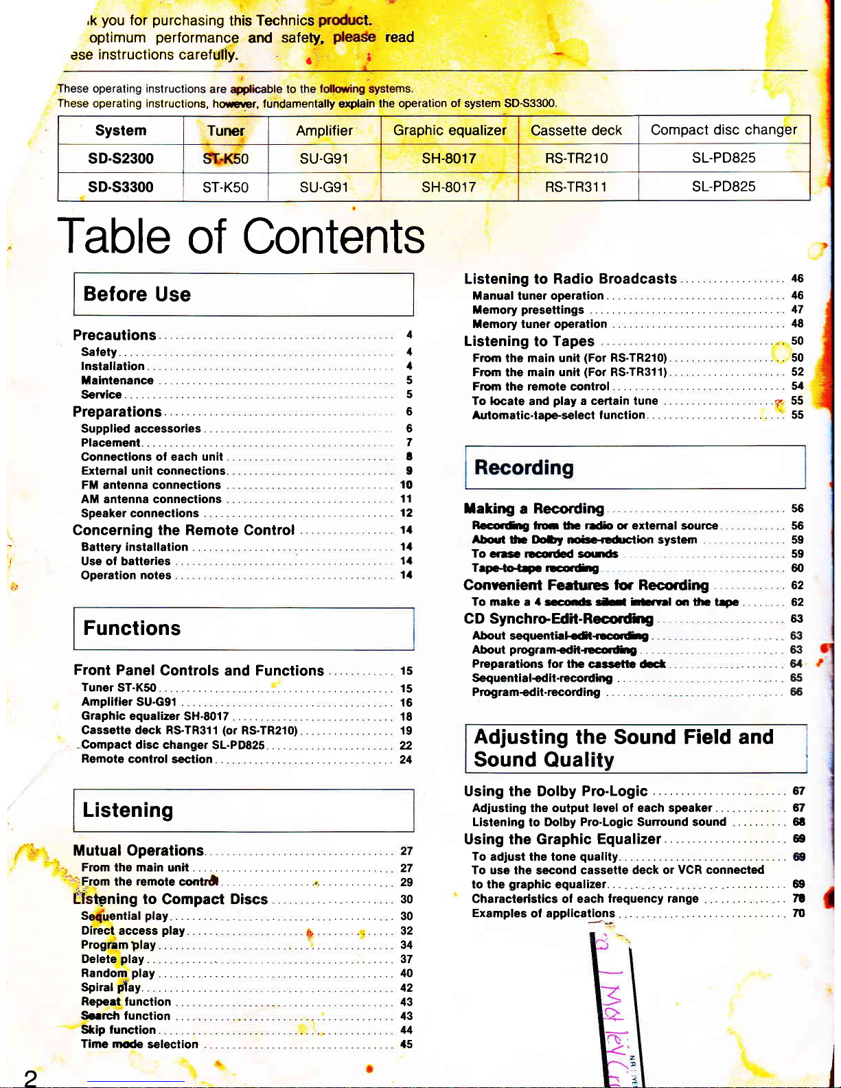
These
operating instructions,
howerrcr, lundamentally explain
the operation
ol
system SD-S3300.
Table
of Contents
Before
Use
'18
s0
50
J
Precautions
Satety. . .
lnstallation
taantenance
Service
Preparations.
. .
Supplied accessories.
Placement.....
Connections of each
unit
External
unit connections.
FM antenna connections
AM antenna connections
Speaker connections
Concerning the Remote Control
Battery installation
Use ol batteries
Operation
notes
Front
Panel
Controls
and
Functions
. ..
is
Tuner
ST-K50
. .. ... 15
Ampliliersu-Gg1 .
..16
GraphicequalizerSH.SOIT
....
18
Cassette deck RSTR3l'l
(or
RS.TR210) 19
-Compact
disc changer
SL.PD825 .
22
Remote
control
section .
24
Listening
"
Mutual Operations
.27
29
Listening to Radio
Broadcasts
. 46
Manual
tuner operation.
.
46
Memorypresettings ....
47
temory tuner operation
Listening
to
Tapes
Frorn the main unit
(For
RS-TR210)
Fromthemainunit(ForRS.TR311)
. ....... 52
Frorn the remote control
. . .
stt
To locate
and
play
a certain iune
?.
55
Aulomatic-lapeseleci lunction
55
1
1
1
5
5
6
6
7
t
I
't0
'tl
12
11
ltl
11
1a
Iaking
a
Recording
Raco.fig
ftu fu
rrlio
or extemal sounee
About
h lloDy riec<cfuakxt system
To cre rEorded
souas
Teptotep rEfiE
Conrenienl Feetures tor Recording
To make
a
4
socd rt
htsrrd
qr
ttrc t+c
C D SynchroEdil-Recorfrrg
About
sequenthlqn<ocolfie
Aboui
programedit+ccorfirg..
,.
-
Preparations
lor lhe
cessgtb rbct
Sequential+d it-recording
Program+dit-rccording
56
56
59
59
60
62
62
6:t
63
6:|
6/t
65
. .. ..,65
1i
Adjusting
the Sound Field and
Sound
Qual
Using the Dolby
Pro-Logic
6t
Adjusting the output level ol each speaker
61
Listening
to
llolby Pro-Logic Surround sound
6t
Using the Graphic
Equalizer
6e
To
adjust the tone
quality
To use the
second
cassette deck or
VCR connected
tothegraphicequalizer...
.....
69
Characteristics ol each
lrequency range
.. .. 7t
Examples
ol applications
m
..
From the main
unit
. . .
4:tiF1om
irr","r"t"
""nrJ
.
,.
tfs6ning to
Compact
Discs
S
ential
play
. . . .. .
30
.30
32
Direct
access
play
#
Delete
play
Random
play
Spiral
flay.
Program
Dlay
Repeat
function
So.rch lunction
Skip tunction.
34
37
40
42
43
43
44
2
System Tuner Amplifier
Graphic equalizer
Cassette
deck
Compact
disc changer
sD.s2300 0 SU.G91
sH-8017 RS.TR21O
SL.PD825
sD.s3300
ST.K50
SU.G91 sH-8017 RS.TR311
SL-PD825
Functions
Time nrode
s€lection . 45
Page 3
77
Additional
Features
Operating
the
VCR or
TV Using
the
Remote
Control
TVoperation.......
VCR operation
.
Reference
Concerning
Compact
Discs
Handling
precautions.
. . . .
.
Storageprecautions.
. .,
. ...
. . .
Concerning Cassette
Tapes
Selection
of casselte
tapes
Erasure
prevention
Tape slack
Tape storage
Before Moving
the Unit.
Maintenance
.....
Head care
Head demagnetization
Maintenance ol external
surlaces
Technica! Specilications
71
71
72
Tuner ST-K50
Afiplllier SU.G91
.......
Graphic
equalizer SH-801
7
Cassette
deck RS-TR210....
....
Casselte
deck
RS-TR311
..
Compact disc
changer SL-PD825
Speaker
SB.A33
(only
for
SD-S2300)
Speaker SB-A53
(only
for SD-S3300)
Speaker
SB.S16A
(only
lor
SD-S3300)
When
There Seems
to
Be
a
Problem
Troubleshooiing
G
Product
Service
...
Product
inlormation
,
lndex
l7
n
n
78
7E
79
79
79
79
{
83
74
74
74
75
75
75
75
75
76
76
76
76
76
uide
..,.
.,.
::
..
82
The
model number and serial
number of this
product
can be
found
on
either the back or
the bottom
o, the unit
Please
note
them
in the space
provided
below
and
retain them
for future reference.
MODEL
NUMBER
SERIAL
NUMBER
I uner :
Amplifier
Graphic equalizer
Cassette deck
Compact
disc changer:
For SL-PD825
THIS PRODUCT
UTILIZES
A LASER.
USE OF CONTBOLS
OR
ADJUSTMENTS
OR PERFOR-
MANCE
OF
PROCEDUBES
OTHER
THAN
THOSE
SPECIFIED
HEREIN MAY
RESULT
IN HAZARDOUS
RADIATION EXPOSURE.
DO NOT
OPEN
COVERS
AND
DO NOT
REPAIR
YOURSELF. REFER SERVICING
TO
QUALIFIED
PER.
SONNEL.
For
SL-PD825,
SU-G91,
RS-TR2l0,
RS.TR3l1
This equipment has been tested
and found
to comply
with the
limits for
a Class
B
computing
device
in accordance
with
the
specifications
set
forth in Subpart J
of Part
15
of
the FCC
Bules
lf this equipment
does
cause interference
to
radio
or
television
reception which
can be determined
by
turning the equipment
on and off, use the equipment
in
anolher
location and/or utilize
an electrical outlet dilferent
f rom that used by
the olher
radio
or
television receiver.
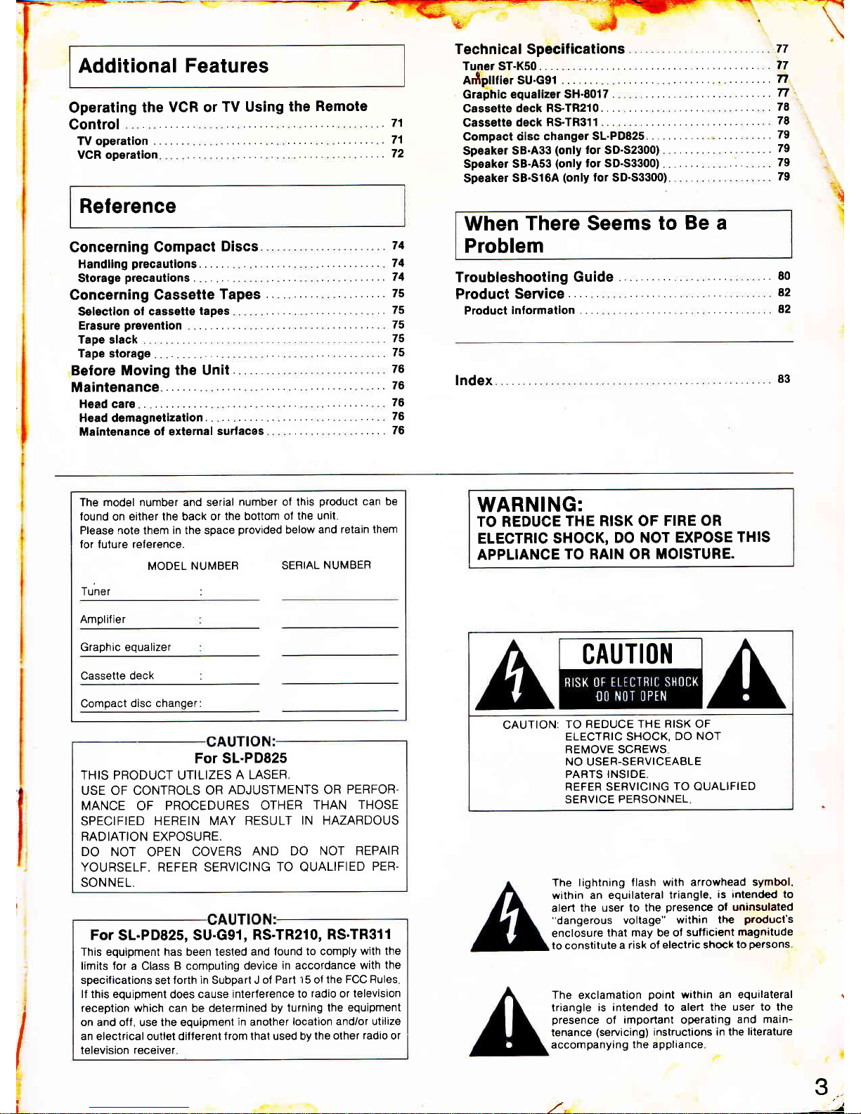
WARNING:
TO REDUCE
THE RISK OF
FIRE OR
ELECTRIC
SHOCK,
DO NOT
EXPOSE
THIS
APPLIANCE
TO RAIN OR MOISTURE.
CAUTI(lI{
CAUTION:
TO REDUCE
THE RISK OF
ELECTRIC SHOCK,
DO
NOT
REMOVE SCREWS
NO
USER-SERVICEABLE
PARTS INSIDE
REFER
SERVICING
TO
QUALIFIED
SERVICE PERSONNEL
The lightning
flash with arrowhead
symbol,
within an equilateral
triangle,
is intended to
alert
the user to the
presence
of
uninsulated
"dangerous
voltage"
within
the
product's
enclosure
that may be ol
sufficienl
magnitude
to constitute
a risk of
electric shock
to
persons.
The
exclamation
point
within an equilateral
triangle
is intended to alert
the user to the
presence
of
important operating
and
main-
tenance
(servicing)
instructions in the
literature
accompanying
the appliance
I
l
3...
--t
Page 4
q-
Precautions
Before using
this
unit
please
read these operating
instructions
carefully.
Take
special care
to follow
the
warnings indicated
on
the
unit itself as well as the
safety suggestions
listed
below.
Aftenrvards keep
them handy lor
future
reference.
t
Safety
1. Power
Sourca - The unit should be connected to
power
supply
only of the type described in the
operating
instructions
or as
marked on the unit.
2.
Polarization - lf
the unit
is
equipped with a
polarized
AC
power
plug
(a
plug
having
one blade
wider
than the other),
that
plug
will
fit into the AC
outlet only one way. This is a safety feature. lf
you
are unable to
insert
the
plug
lully into the
outlet,
try reversing the
plug.
ll
the
plug
should still lail to fit, contact
your
electrician to
replace
your
obsolete outlet. Do not defeat the safety
purpose
of
the
polarized plug.
3.
Power
Cold
Plotection
-
AC
power
supply cords should be
routed so that they are not likely
to
be walked on or
pinched
by
items
placed
upon or against them.
Never
take hold of the
plug
or
cord if
your
hand is wet, and always
grasp
the
plug
body when
connecting or disconnecting
it.
4.
Nonuse Periods
-
When the unit
is not
used, tum the
power
off.
When left unused for a long
period
of time, the unit should
be
unplugged
from
the
household AC
outlet.
Insta!!ation
Environmeht
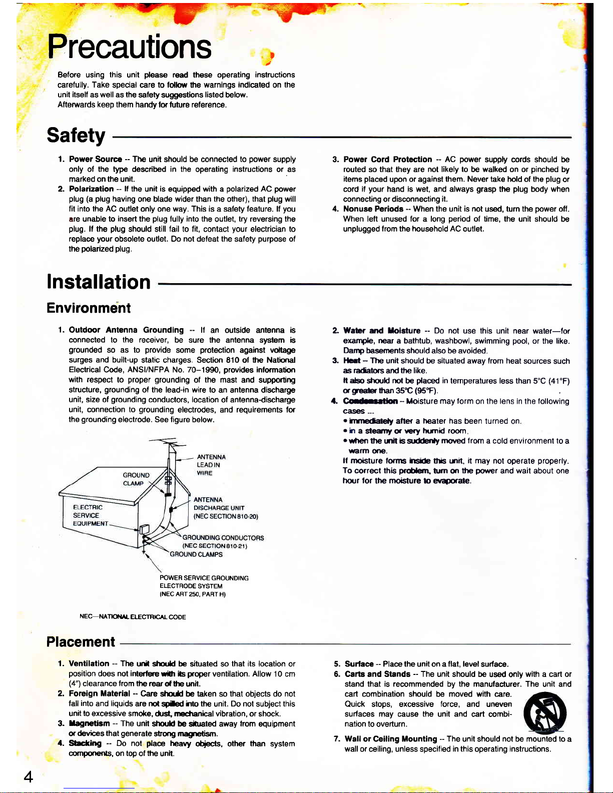
1.
Outdoor Antenna Grounding
--
lf
an ouiside antenna b
connected to the receiver,
be sure the antenna system
b
grounded
so as to
provide
some
protection
against
voltage
surges and built-up
static charges. Section 810 of the Natbnal
Electrical
Code,
ANSI/NFPA
No. 70-1990,
provides
inlormatbn
with
respect
to
proper grounding
of
the mast
and supportirg
structure,
grounding
ol the lead-in wire to
an antenna discharge
unit, size of
grounding
conductors, location
of antenna-discharge
unit, connection to
grounding
electrodes, and requirements for
the
grounding
electrode. See figure below.
POWER
SERVICE GROUNDING
ELECTROOE
SYSTEM
(NEC
ART
2sO, PABT
H)
NEC-MTEI"AL
ELECTRICAI.
CODE
2. Wabr ad loisture
-
Do not
use this unit near
water-for
exampb,
near
a bathtub, washbowl,
swimming
pool,
or the like.
Darp basements
should also be avoided.
3. Hc.t
-
The
unit should be situated away trom heat
sources
such
as
radabIs
and
the like.
It
abo
strould rct be
flaced
in
temperatures less
than 5"C
(41"F)
agrE*rthan
35t
(95'F).
A
C*rfion
-
Moisture may form
on the lens in the following
calEs
---
o'rrmedaleNy
after a
heater has
been turned
on
.
h
a
steenty
q
rery
trrnil room
o
when the
mit
is
s.tffiy
rnoved from
a cold
environment
to
a
warn
dre.
lf rnoisture
,oflns irsb tis l.rlil,
it
may not
operate
properly.
To
@rrect
this
prdetrl'
tnn
qr
lfp
power
and
wait
about one
turr for
the
moisture
lo eYaporde.
Placement
1. Ventilation
--
The
uln sfiouad be
situated so
that its location
or
position
does
not interfure
rlh ils
proper
ventilation.
Allow
10 cm
(4")
clearance from ttp reardthe
unit.
2. Foreign Material
--
Carc
stELS be taken so that objects do
not
tall
into
and liquids
are
not
spfed
irto the
unit.
Do not
subject
this
unit
to
excessive smoke,
dst ncdanical vibration, or shock.
3.
llagnetlsm
-
The unit
should be
strrated away
lrom
equipment
or
devices that
generate
stong
,nagrEtism.
a.
$acfhg
-
Do not
place
heavy
otiecfs, other
than
system
components,
on
top
of
the
unit.
Surlace
-
Place the unit on a flat, level
surface.
Carts and Stands - The unit should be
used only
with a cart or
stand that is recommended by the manufacturer. The
unit and
cart combination should be moved with care.
Quick stops, excessive
force,
and uneven
surfaces may cause the unit and
cart combi-
nation
to overturn.
7. Wall
or Ceiling Mounting
-
The
unit should
not
be mounted to a
wall
or ceiling, unless specified
in this
operating
instructions.
5.
6.
4
Page 5
M
a
i
ntena
nGe
(see pase
76 ror
detairs)
-$','r
Clean
the cabinet,
panel
and controls
with a
soft cloth
lightly
moistened
rvith mild detergent
solution.
Do
not use any
type of
abrasive
pad,
scouring
powder
or
solvent
such as alcohol
or
benzine.
Service
1. Damage Requaring
Service
--
The unit should
be serviced
by
qualitied
service
personnel
when:
(a)
The AC
power
supply cord
or the
plug
has been damaged;
or
(b)
Objects
have
fallen or liquid
has been spilled
into the unit; or
(c)
The unit
has been exposed
to rain; or
(d)
The unit does
not
appear
to operate
normally or exhibits
a
marked change
in
performance;
or
(e)
The unit
has been dropped,
or
the enclosure damaged.
2. Servicing
-
The user should
not attempt
to service
the unil
beyond
that described
in the operating
instruciions.
All other
servicing
should
be
refened
to
qualified
service
personnel.
Page 6
r-
--=aEF-a@=
E!F-
:-''-
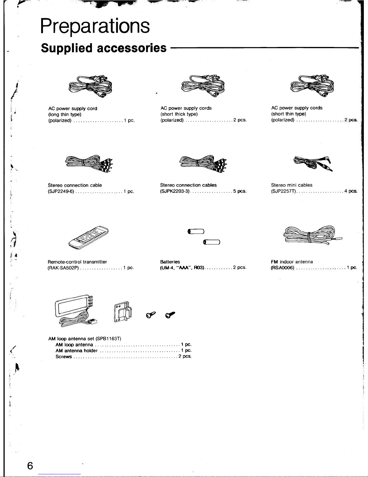
AC
power
supply cord
(long
thin
type)
(polarized) .. 1pc
Stereo connection
cable
(SJP2249-6)...
.. ...1
pc.
AC
power
supply
cords
(short
thick type)
(polarized) 2
pcs.
AC
power
supply
cords
(short
thin type)
(polarized)
Stereo
mini cables
(sJP2257T).
FM
(RS
Remote-control transmitter
(RAK-SA5O2P)
..........1pc.
€r
€,,
AM loop antenna set
(SPBI
163T)
AM loop antenna
. .
.. .. 1
Pc.
AM antennaholder.
.........1Pc.
Screws
....2pcs.
/
''r,
i
I
6
Preparations
Supplied accessories
HkF
w
Slereo
connection cables
(SJPK2203-3).
.........5pcs
D
D
Baileries
(UM{,
"MA".
m).-
..2
Pcs.
Page 7
t-.'d
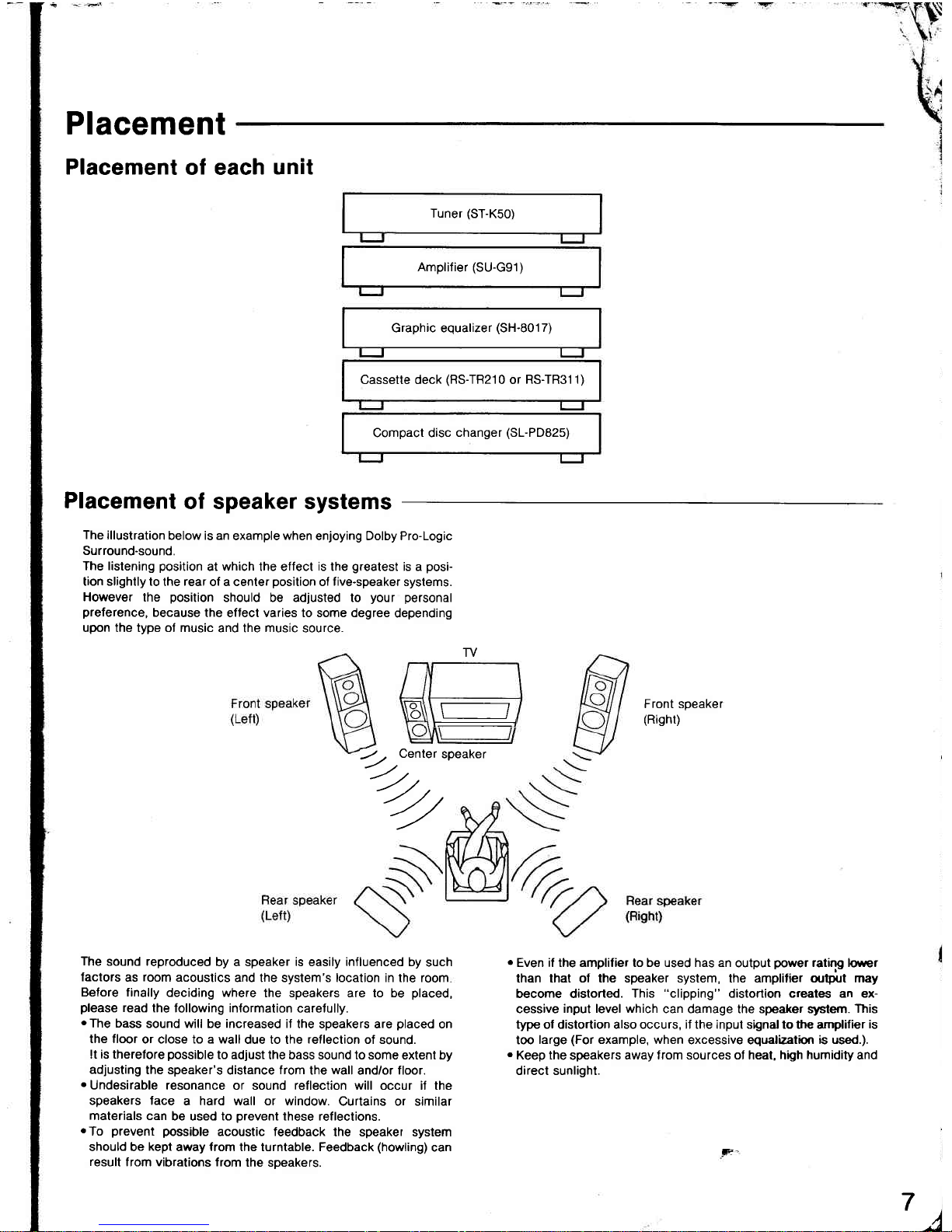
Placement
Placement
of each
unit
Tuner
(ST-K50)
Amplifier
(SU-G91)
Graphic equalizer
(SH-801
7)
Cassette deck
(RS-TR210
or
RS-TR311)
Compact disc
changer
(SL-PD825)
Placement
of speaker systems
The
illustration
below is an
example
when
enjoying Dolby Pro-Logic
Surround-sound.
The listening
position
at
which
the effect
is
the
greatest
is a
posi-
lion slightly to
the
rear
of a center
position
of
five-speaker
systems.
However
the
position
should be adlusted to
your personal
preference,
because
the eflect varies to some degree
depending
upon the type ol music
and the
music
source.
TV
o\,
o\
c
E]
i-J
Front speaker
(Risht)
--4)",speaker
7,2,,
-/
o
Even if the amplifier to be used has an
output
power
rating lo*er
than that ol the speaker syslem, the amplifier ou$rt may
become distorted.
This
"clipping"
distortion creates an ex-
cessive
input level which
can damage the speaker slts{em.
This
type ol distortion also occurs, if the input signal to the amplifier
is
too
large
(For
example, when
excessive equalizatiqr
is used.).
.
Keep the
speakers
away from sources of heat, high
humidity
and
direct sunlight.
The
sound reproduced
by a speaker is easily influenced by
such
lactors
as
room
acoustics
and the system's location in the room
Before finally
deciding where
the speakers are to be
placed,
please
read
the lollowing information
carelully.
oThe
bass
sound will be increased if
lhe speakers are
placed
on
the floor
or close to a wall
due to the
reflection
of sound.
It is therefore
possible
to adjust
the bass sound to some extent by
adjusting
the speaker's
distance
from
the
wall
and/or floor.
.
Undesirable resonance
or sound
reflection
will occur i, the
speakers face
a hard wall or window.
Curtains or similar
materials can
be used to
prevent
these reflections.
.To
prevent
possible
acoustic feedback
the speaker system
should be
kept
away
from
the turntable. Feedback
(howling)
can
result
from vibrations from
the speakers.
e=
?)
Page 8
trtr
trE
trE
NE
trtr
I
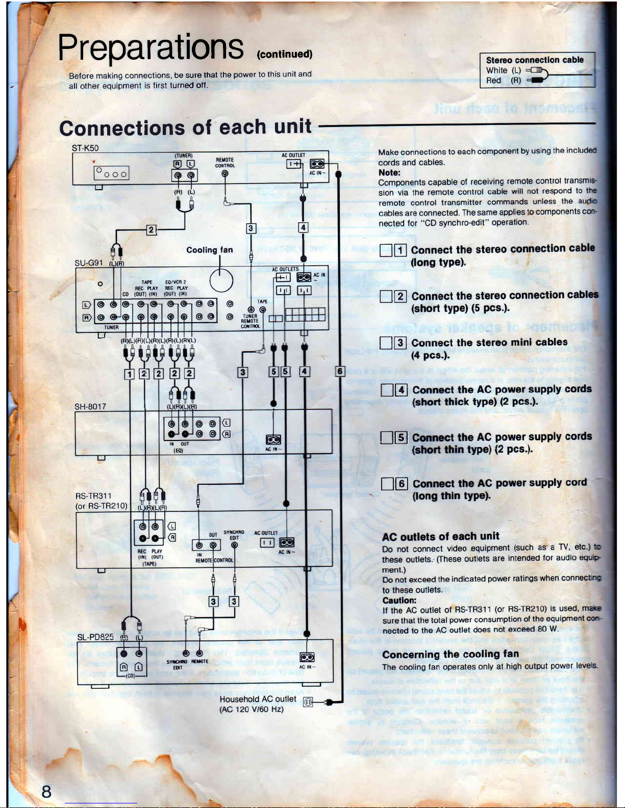
Preparations
(conrinued)
Belore
making
connections,
be sure
that
the
power
to this
unit and
all other
equipment
is first
turned off.
Gonnections
of
each
unit
3
,l
Cooling
lan
SU.G91
I
I
L^*
6o
TUIER I
RErorE I
corrmr
I
o
@
@
@@
@o
TAPI Eo/VCR
2
REC
PI.^Y
REC PIAY
fi{)
(oun
oil)
TUI{ER
J
sH-8017
LXFX
lI
I
5l
lr
G
@
J
RS.TR311
(or
RS-TR210)
I
\
(t
}H
rr
R)Y
LJ
(
lA2E rdr
iffi
e,,,q
#
JJ
sYf,rfi)
Erolt
m
,u
I
I
E
I
_)
Page 9
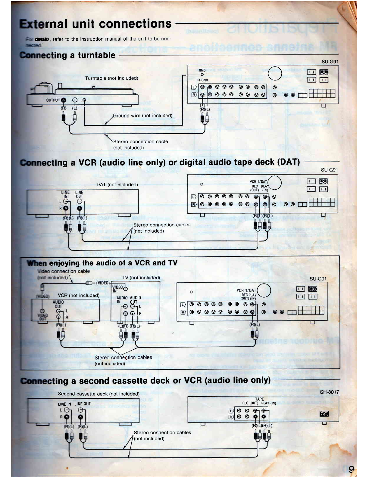
rnal unit
connections
eaails,
refer
to
the instruction
manual of
the unit to be
con-
ng a turntable
ng a
VCR
(audio
line only)
DAT
(not
included)
or digital
audio
tape deck
(DAT)
deck
or
VCR
(audio
line onlY)
ng
a second
cassette
Second
cassette deck
(not
included)
o
SU€91
Turntable
(not
included)
wire
(not
included)
o
o
@
o@@ @@
@@
o@@ o@
@@
enjoying
the
audio of a
VCR
and
TV
VCR
(not
included)
o
r@
l.
@@@@@
@@
@
@@@o@@@o
AUDIO
OUT
G1
L
ol*
SU-G91
Stereo
conneqtion
cables
(not
included)
LlilE
lN Lll'lE
oUT
Stereo
connection cables
(not
included)
Stereo connection cable
(not
inclucled)
SU-G91
ua*,roorA
Rec
puV.
)
1our1 1rn1v
3
@@
rTrffi
@@o@@ @@
@@@@@
@@
Stereo
connection cables
(not
included)
sH-8017
TAPE
REC
(OUT)
PLAY
(IN)
@@
o@
E
Page 10
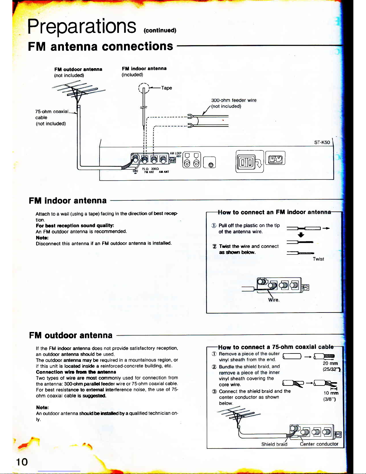
Preparations
(conrinued)
FM antenna
connections
FM outdoor
antgnna
(not
included)
FM
indoor
antenna
(included)
,t-TaPe
75-ohm
cable
(not
included)
FM indoor
antenna
Attach to a
wall
(using
a tape)
facing in the direction
of
best
receP
tion.
For best
r€captlon sound
quality
An FM outdoor
antenna
is recommended.
Note:
Disconnect this antenna
if an FM outdoor
antenna
is installed.
FM
outdoor
antenna
lf
the
FM indoor antenna does
not
provide
satislactory
reception,
an outdoor anlenna
should be used
The outdoor
antenna may be
required in a mountainous
region,
or
if this unit
is located inside a
reinforced-concrete building,
etc.
Connectlon
wlro lnor
tlrs
entenna
Two types of
wire are most commonly used
for connection
Jrom
the antenna: 300ohm
parallel
leeder wire or
75-ohm
coaxial cable.
For
best
resistance to er(emal
interference
noise, the
use ol
75-
ohm coaxial cable
is
suggested-
Note:
An
outdoor antenna shonld be
irslalled by a
qualif
ied technician
on-
ly.
Twist the wire and connect
as slrown bebrv.
'
Twist
to connect
a
75-ohm coaxial
to connect an
FM indoor
O
tull off the
plastic
on the tip
of the antenna
wire.
._l+
I
tu
z
O
f-)-*[._Hl
@
20mm
(zst32'1
vinyl sheath
covering
the
corewire.
rEp*lR:
O
Gonnect
the
shield braid
and the
-
,o [*
center conductor
as shown
(3/g,,)
below.
F
10
75
()
3000
FM ANT
AT A"I
ffie
@@
Page 11
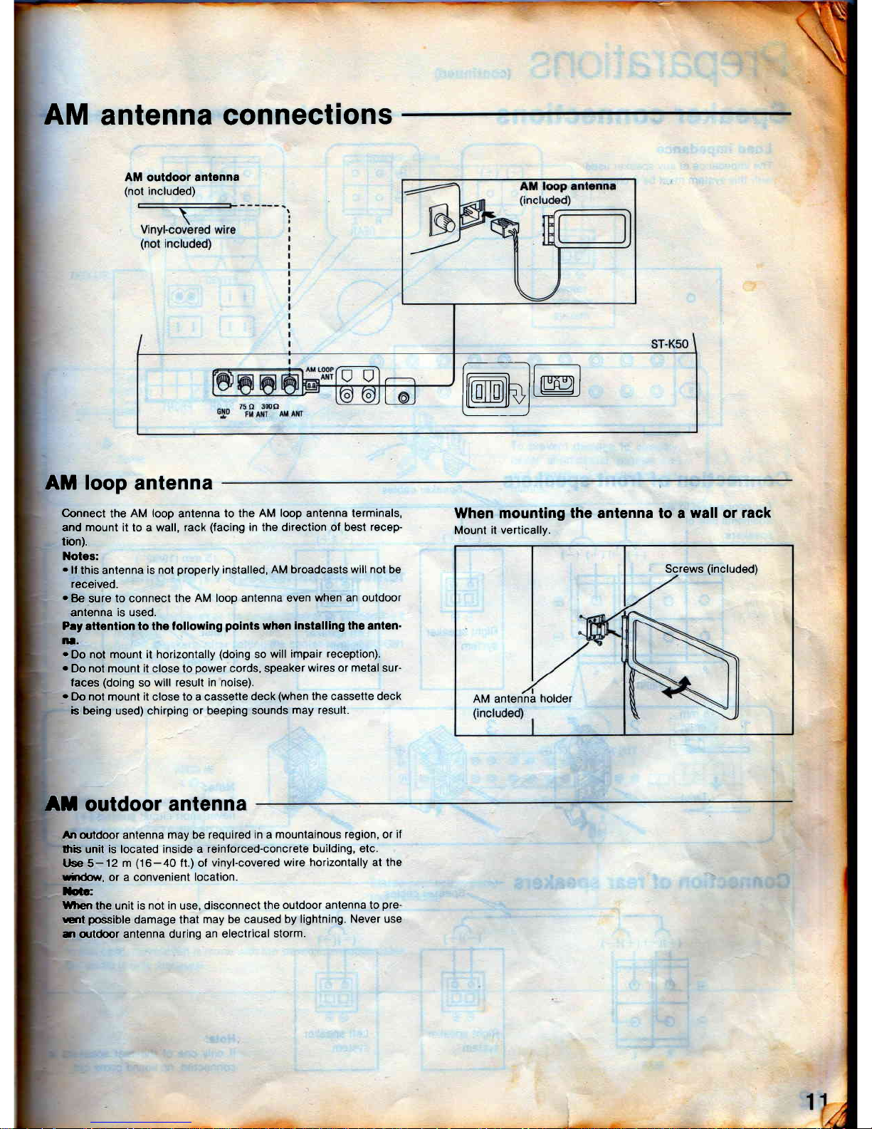
AM
antenna connections
AM outdoor antenna
(not
included)
r__-l
ItmhllL@i
t.--l
AM loop
antenna
Connect
the
AM loop
antenna
to the AM
loop
antenna terminals,
and mount it to a wall,
rack
(facing
in the direction of best
recep-
tion).
Notes:
.
ll
this antenna
is not
properly
installed,
AM broadcasts will
not
be
received.
o
Be
sure
to connect the
AM loop antenna even
when an outdoor
anlenna
is used.
P.y attention to the lollowing
points
when
installing
lhe anten-
lrl-
.
Do
not mount il horizontally
(doing
so
will impair
reception).
o
Do not mount it close to
power
cords, speaker
wires or
metal
sur-
faces
(doing
so
will result in noise).
o
Do nol mount it close to a cassette
deck
(when
the cassette
deck
b
being used) chirping or beeping sounds
may result.
When
mounting the antenna to
Mount
it vertically.
a
wall or rack
AM antenna
holder
Screws
(included)
At outdoor antenna
An
outdoor antenna
may
be
required
in
a
mountainous region, or
if
$'rs unit is located inside a
reinlorced-concrete
building, etc.
t se 5-12
m
(16-40
ft.) ol
vinyl-covered
wire horizontally at the
rirdot,Y,
or a convenient
location.
Ioic:
When
the unit
is not in
use,
disconnect the
outdoor antenna to
pre-
crt
possible
damage that
may be caused
by lightning. Never
use
il
q.rtdoor
antenna during
an electrical
slorm.
Page 12
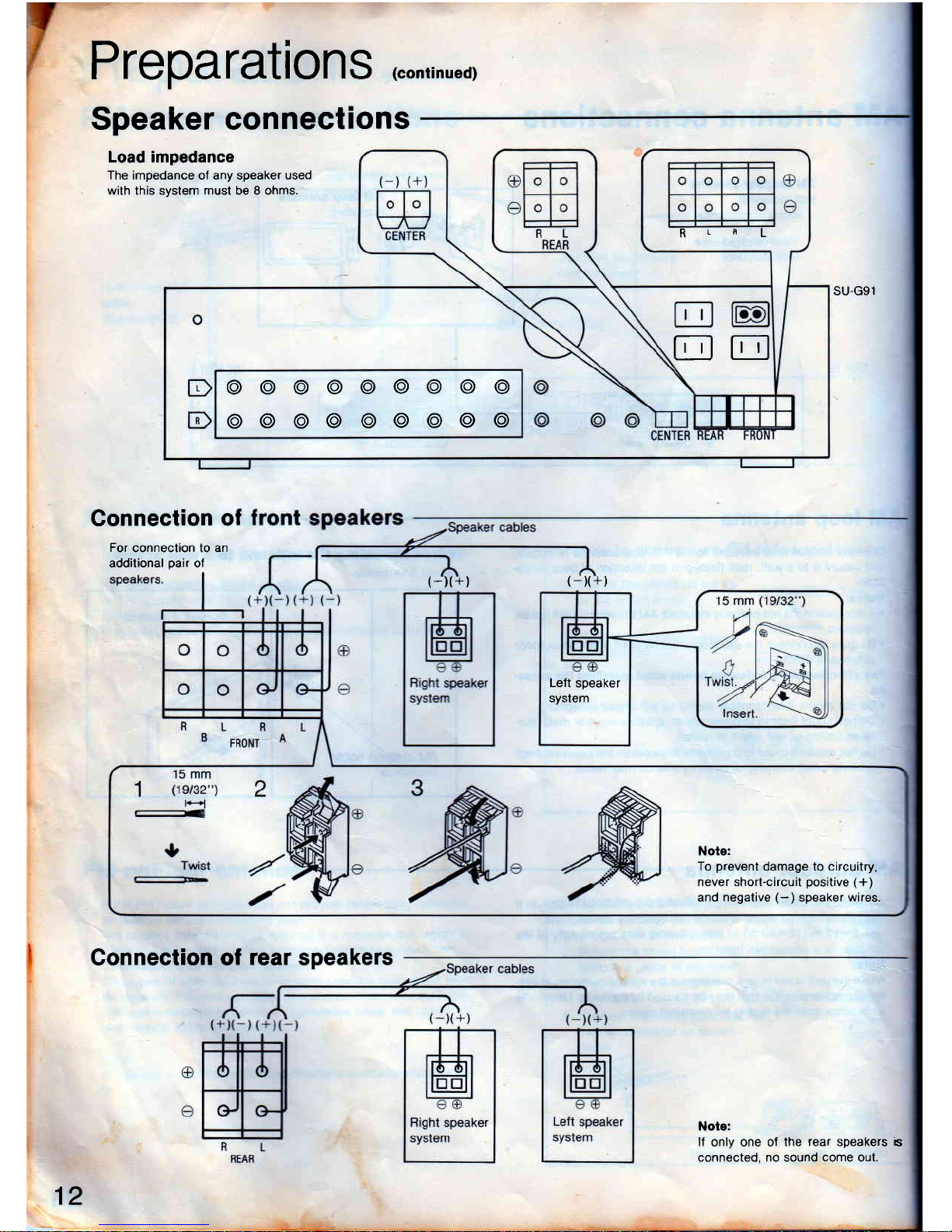
Preparations
(conrinued)
Speaker connections
Load impedance
The impedance oI any speaker used
with this system musl be 8 ohms.
Connection
of
For
connection to an
additional
pair
of
RLf,L
EE
@o@@@@@o@
@@@@@@@@@
SU-G91
(-)(+)
(-x+)
Left
speaker
system
Note:
To
prevent
damage to circuitry,
never short-circuit
positive
(+)
and
negative
(-)
speaker wires.
Connection of
rear
speakers
Note:
lf
only one of
the rear speakers
b
connected, no sound
come
out.
12
Page 13
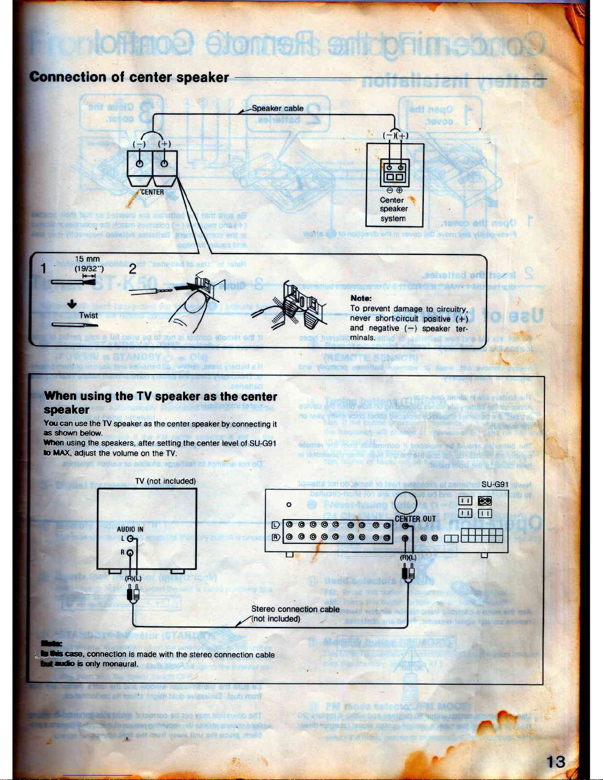
of
center
speaker
minals.
WJren
using the
TV
speaker as the
center
speaker
Yqr
can use the TV
speaker as the
center speaker by
connecting it
c sfiown below.
When
using the
speakers, after
setling the center level
ol SU-Gg1
b
MA)(,
adjust
the volume
on the TV.
TV
(not
included)
AUDIO IN
L
R
E
;.llf,rcase,
connection
is made
with the
stereo connection
cable
SU.G91
E@
oUT
EE
@@@@@
@@@o@
@
@
@@
-rro
b only monaural.
Page 14
I
Open the
I
couer.
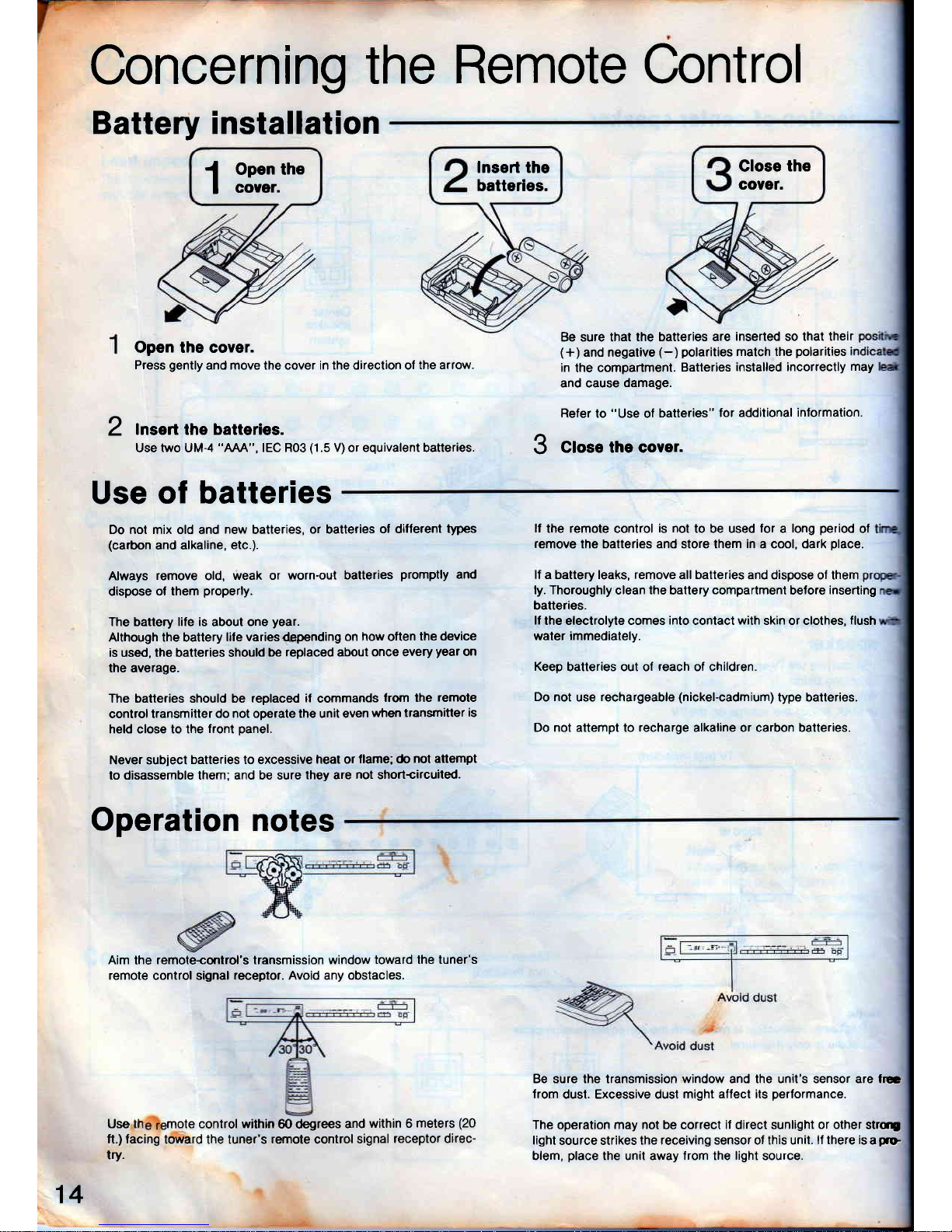
Concerning
the
Remote Control
Battery installation
Open the coYer.
Press
gently
and move the cover in the direction o,
the arrow.
lnsert the batteries.
Use
two
UM-4
"AAA",
IEC R03
(1
.5 V) or equivalent batteries.
Be sure that the batteries are
inserted so that theil
(+)
and negative
(-)
polarities
match the
polarities
in
the
compartment.
Batteries
installed incorrectly
may
and cause
damage.
Refer
to
"Use
of
batteries"
for additional
information.
J
Close the cover.
lf
the remote control
is not
to be used
lor
a
long
period
of
remove
the batteries and store them in a cool, dark
place.
lf a battery leaks, remove all batteries and
dispose ol them
ly. Thoroughly
clean
the
battery
compartmenl
before
inserting
batteries.
lf
the electrolyle comes
into
conlact
wiih
skin or clothes,
flush
water immediately.
Keep
batteries out of
reach
of children.
Do not
use
rechargeable
(nickel-cadmium)
type batteries.
Do not attempt to recharge alkaline or carbon batteries.
Be sure the iransmission window and the unit's sensor are frE
from
dust. Excessive dusl
might affect its
performance.
The operation may not be correct
il
direct sunlight
or other
strq
light
source strikes
the receiving sensor ol this unit.
lf there is
a
p.D
blem,
place
the unit away from the
light
source.
lnsert the
batteries.
Glose
the
covet.
2
Use
of batteries
Do not mix old and
new
batteries,
or batteries
of different
types
(carbon
and alkaline,
etc.).
Always
remove
old,
weak or
worn-out batteries
promptly
and
dispose
of them
properly.
The battery life is about one
year.
Although the battery
lile varies@pending
on how oflen
the device
is used, the batteries should
be
replaced
about
once every
year
on
the average.
The batteries should be replaced
if
commands
lrom the
remole
control transmitter
do not operate the unit even
when
transmitter
is
held close to the
front
panel.
Never subiect
batteries to excessive
heat or
flame; do
not attempt
to disassemble them; and be sure
they are
not
shortcilcuited.
Operation
notes
Aim
the
remote{ontrol's transmission window
toward the tuner's
remote
control signal
receptor. Avoid any obstacles.
Use th mote control within
@ degrees
and
within 6
meters
(20
ft,)
facing
toward the tuner's
remote
control
signal
]eceptor direc-
try.
14
Page 15
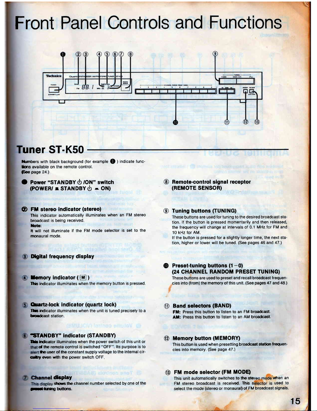
Front
Panel
Controls
and
Functions
uner
ST-K50
l
15
lfumbers
with black background
(for
example
Q
)
indicate func-
lins available on
the remote control.
Fee
page
24.)
O
Power
"STANDBY
<b
to]\l'switch
(POWER,
r
STANDBv$
-
Ottl
(D
FXI stereo
indicator
(stereo)
This
indicator automatically
illuminates
when an FM stereo
broadcast
is
being
received.
Xote:
h will
not illuminate
if the FM
mode selector
is set to
the
rnonaural mode.
IXgita! frequency display
Iemoryindicator(E)
rlfs indicator illuminates
when the
memory button is
pressed.
'Onrtz-lock
indicator
(quartz
lock)
rlB indicator illuminates when the unit
is
tuned
precisely
to
a
bErbast
station.
iSTANDBY"
indicator
(STAN
DBY)
,lE
irdicator illuminates when the
power
switch of this unit or
dthe remote control
iS
switched
"OFF". lts
purpose
is
to
te user of the constant
supply
voltage to the
internal cir
qi1l
erren
with the
power
switch OFF
dloplay
silws the
channel
number selected
by one of the
@
Remote-control signal
receptor
(REMOTE
SENSOR)
@
Tuning buttons
fiUNING)
These
buttons
are used for tuning to the desired
broadcast sta-
tion.
lf
the button
is
pressed
momentarily and then
released,
the lrequency
will change al intervals of 0.1
MHz for FM and
10 kHz
lor AM
lf the button is
pressed
for a slightly
longer time, the next sta-
tion,
higher or lower will be tuned.
(See pages
46 and
47.)
@
Preset-tuning buttons
(1-0)
(24
CHANNEL
RANDOM PRESET TUNTNG)
These buttons are used
lo
preset
and recall broadcast
frequen-
cies into
(from)
the
memory
of
this unit.
(See
pages
47 and
48.1
Band selectors
(BAND)
Fil:
Press this
button to
listen to an FM broadcast.
At:
Press this
button to
listen to an
AM
broadcast-
Memory button
(MEMORY)
This button
is
used
when
presetting
broadcast s{atim
frequen-
cies into
memory.
(See
page
47.)
o
@
@
FM mode selector
(FM
IUODB
This
unit automatically
switches
to the ste
'when
an
FM stereo
broadcast
is
received.
This s
used
to
select
the mode
(stereo
or
monaural) ol
FM broadcast
signals'
ll-fihg
hrttqrs.
L'
Page 16
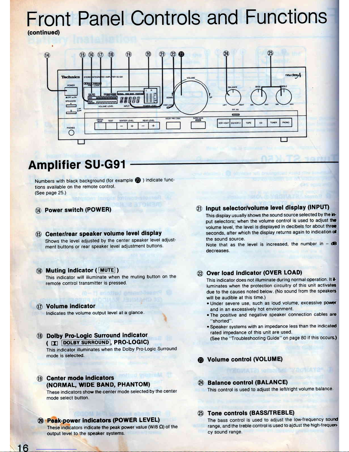
Front
Panel
Controls
and
Functions
(continued)
Amplifier
SU-G91
Numbers
with
black background
(for
example
@
)
indicate
func-
tions
available
on
the
remote
control.
(See
page
25.)
@
Power
switch
(POWER)
@
Centerlrear
speaker
volume
leve! display
Shows
the
level
adjusted
by
the center
speaker
level
adjust-
ment buttons
or
rear speaker
level ad.lustment
buttons.
@
Muting
indicator
(
lMUrEl)
This indicator
will illuminate
when the
muting
button
on the
remote
control
transmitter
is
pressed.
@
Volume
indicator
lndicates
the
volume
output
level at
a
glance
@
Dolby
Pro-Logic
Surround
indicator
1
5
loot-sY.suRRouNE,
PRO-LOGIC)
This
indicator
illuminates
when
the
Dolby
Pro-Logic
Surround
mode
is selected,
Center
mode
indicators
(NORMAL, WIDE
BAND,
PHANTOM)
These
indicators show
the center
mode
selected
by
the
center
mode
select
button.
Peak-power
indicators
(POWER
LEVEL)
These indicators indicate
the
peak
power
value
(W/8
O) ol
the
output
level
to
the
speaker
systems.
@
lnput setectorlvolume
level
disPlay
(INPUT)
This display
usually
shows
the
sound
source
selected
by the
i>
put
selectors;
when
the
volume
control
is used
to
adiust
tl:
volume
level, the
level
is
displayed
in decibels
for about
thlec
seconds,
after
which
the display
returns
again
to
indication
d
the sound
source.
Note that
as the
level
is
increased,
the
number
in
-
6
decreases.
@
Over
load indicator
(OVER
LOAD)
This
indicator does
not
illuminate during
normal operation.
lt 1
luminates
when the
protection
circuitry
of
this unit
activat6
due to
the causes
noted below
(No
sound
Jrom the
speakes
will be
audible
at this
time.)
.
Under severe
use,
such as
loud volume,
excessive
porrer
and
in an excessively
hot environment.
.
The
posilive
and
negative
speaker
connection
cables are
"shorted".
.
Speaker systems
with an
impedance
less than the
indicated
rated impedance
of
this unit
are used.
(See
the
"Troubleshooting
Guide"
on
page
80
if
lhis
occurs)
@
Volume control
(VOLUME)
@
Balance
control
(BALANCE)
This control
is used
to
adjust
the left/right
volume
balance-
@
Tone controls
(BASSTTREBLE)
The
bass
control
is used
to
adjust
the low-frequency
sound
range,
and the
treble
conlrol
is
used
to ajdust
the
high-frequeG
cy
sound
range.
@
@
16
Page 17
l-
e
G
f,
B
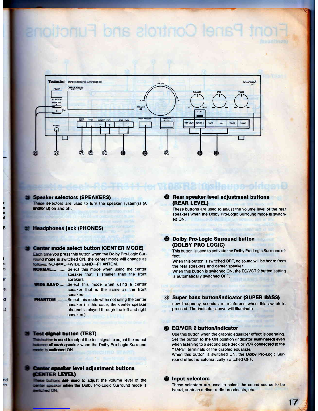
selectors
(SPEAKERS)
selectors
are used to turn the speaker system(s)
(A
rer B)
on and off.
jack
(PHONES)
mode
select
button
(CENTER
MODE)
you
press
this button when the
Dolby Pro-Logic Sur'
rrode is
switched ON,
the center
mode will change as
NORMAL-WI
DE BAND-PHANTOM.
........... Select this mode
when using the center
speaker
that is smaller than
the lront
sprakers
lAllD........Select
this
mode when using
a center
speaker
that is the same
as the front
Rear
speaker
leyel adiustment buttons
(REAR
LEVEL)
These
buttons
are used
to adiust the
volume
level of the
rear
speakers
when
the Dolby Pro-Logic Surround mode
is
switch-
ed ON.
Dolby Pro-Logic Surround
button
(DOLBY
PRO LOG|C)
This button
is used to activate
the Dolby Pro-Logic
Surround ef-
lect.
When this button
is switched OFF,
no
sound
will be
heard from
the rear speakers
and center speaker.
When
this
button
is
switched
ON, the EOI/CR
2 button setting
is automatically
switched OFF.
Super bass buttonlindicator
(SUPER
BASS)
Low frequency
sounds are
reinforced
when this sitch b
pressed.
The
indicator
above will illuminate.
EOruCR
2
button/indicator
Use this button
when
the
graphic
equalizer effect b
operating.
Set the button
to the ON
position
(indicator
ilhrminated)
eireri
when
listening to a
second
tape deck or VCB curEcted to
the
"TAPE"
terminals of the
graphic
equalizer.
When this button is switched ON, the DoDy
Pro-Logic Sur-
round
eflect
is automatically switched OFF-
!nput
selectors
These
selectors
are used to select
the
sound
source
to be
heard, such as
a disc, radio broadcasts,
etc.
o
@
o
,
ffi'.'
l.
s
ts
speakers
---.....Select
this
mode when
not
using
the center
@
speaker
(ln
this
case, the
center speaker
channel
is
played
through
the lelt and right
speakers).
.tn
l
button
(IEST)
B
used to output the test signal to adjust the output
ddr speaker
when the Dolby Pro-Logic Surround
rt
pd
ON.
S*.r
level adjustment buttons
I-EYEL)
G used to adjust
the volume
level
of the
-Er
tte
Dolby Pro-Logic Surround
mode is
o-oo
@
17
Page 18
F
Front
Panel
Controls
and
Functions
(continued)
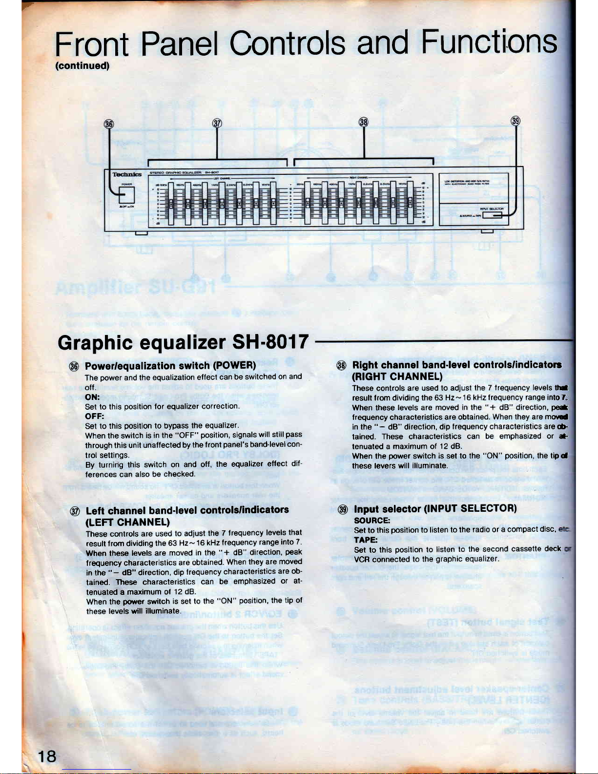
Graphic
equalizer
SH-801
7
@
Powerlequalization
switch
(POWER)
The
power
and the
equalization
effect
can be
switched
on and
olf.
ON:
Set
to this
position
for equalizer
correction.
OFF:
Set to
this
position
to bypass
the equalizer.
When the switch
is in the
"OFF"
position,
signals
will still
pass
through
this unit
unalfected by
the
front
panel's
band-level
con-
trol settings.
By
turnirig this
switch on
and otf,
the equalizer
effect
dif-
ferences
can
also be
checked.
@
Left channel
band-level
controlslindicators
(LEFT
CHANNEL)
These
conlrols
are used
to adiust
lhe
7 frequency
levels
that
resull from dividing
the
63 Hz-16
kHz
frequency
range
into 7.
When
these
levels are
moved
in the
"+
dB"
direction,
peak
frequency
characteristics
are obtained.
When
they are
moved
in the
"
-
dB" direction,
dip
lrequency
characteristics
are ob-
tained.
These characterislics
can
be
emphasized
or al-
tenuated
a maximum
of
12 dB.
When the
pofler
switch
is
set
to lhe
"ON"
position,
the
tip of
these
levels will
illuminate.
@
Right
channel
band-level
controlslindicators
(RTGHT
CHANNEL)
These conlrols are
used to adjust
the 7 trequency
levels
tE
result lrom dividing
the 63
Hz- 16 kHz lrequency
range intoT-
When these
levels are moved
in
the
"+
dB" direction,
peat
frequency characteristics
are obtained.
When they are
mod
in the
"
-
dB" direction,
dip
frequency characteristics
are
G
tained,
These charactelistics
can
be emphasized or *
tenuated a
maximum of
12
dB.
When the
power
switch
is set to the
"ON" position,
the tipd
these levers
will illuminate.
@
lnput selector
(INPUT
SELECTOR)
SOURCE:
Set to this
position
to listen
to the
radio or
a compact
disc,
TAPE:
Set to
this
position
to
listen
to the second
cassetle
deck
VCR connected
to the
graphic
equalizer.
18
Page 19
CO
STEREO
Iru
ASTE
4CK
GTR3II
?
C
a
ffi
a
RS.TR311
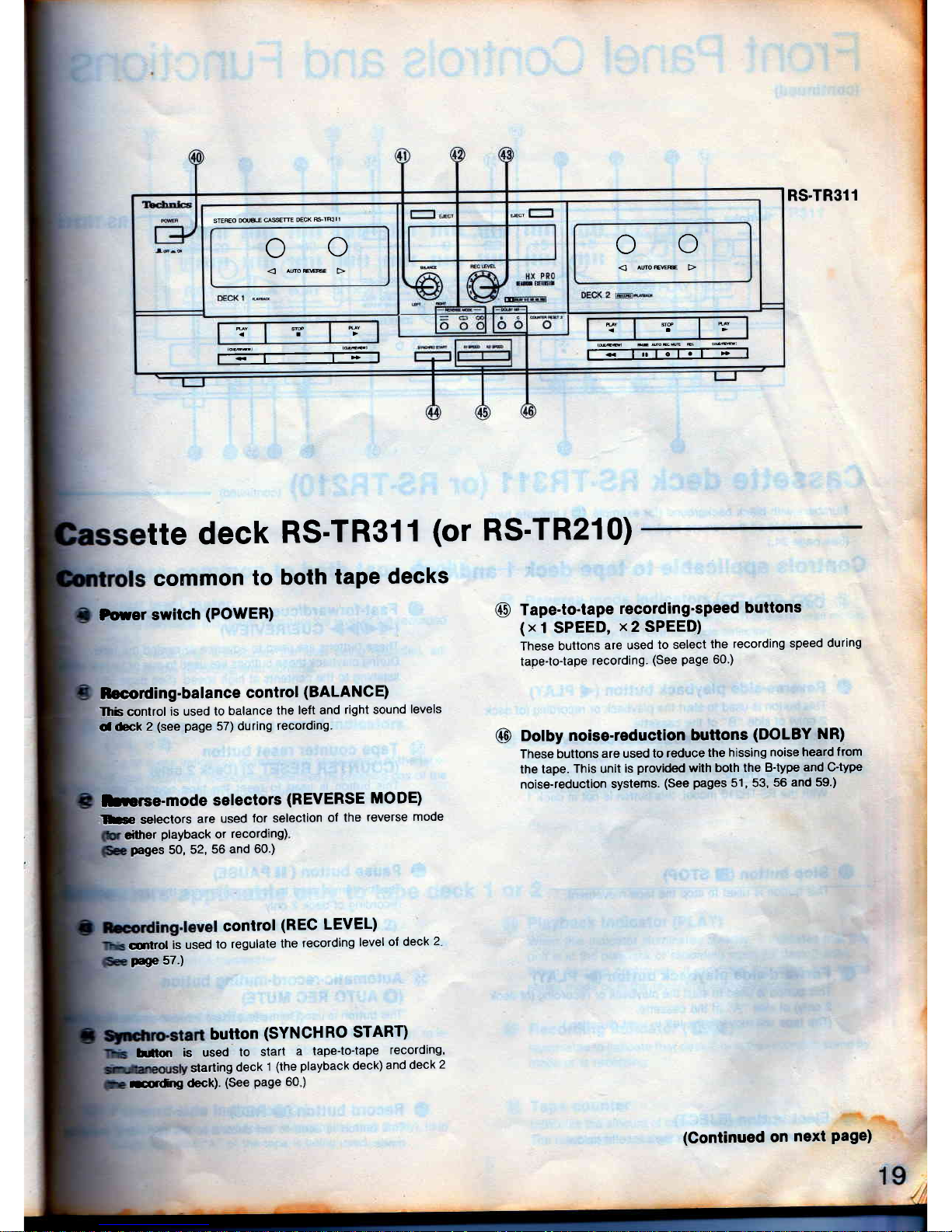
@
Tape-to-tape
recording'speed
buttons
(xl
SPEED,
x2
SPEED)
These
buttons
are used
to select
the
recording
speed
during
tape-to{ape
recording.
(See
page
60')
@
Dolby noiss-reduction
buttons
(DOLBY
NR)
These
buttons
are used to
reduce
the
hissing
noise heard
from
the tape.
This unit
is
provided
with both the
B'type
and C-type
noise-reduction
systems.
(See
pages
51, 53,
56 and
59.)
tte
deck
RS-TR3l
1
(or
RS'TR210)
coinmon
to
both
tape
decks
Douer
switch
(POWER)
trecoding-balance
control
(BALANC
E)
Thb control
is used
to
balance
the
left and
right sound
levels
d
&ck
2
(see
page
57) during
recording.
Drerce-mode
selectors
(REVERSE MODE)
Lte
selectors
are
used
for selection
of the
reverse
mode
dther
playback
or
recording)
pages
50,
52,
56 and
60.)
control
(REC
LEVEL)
qilrol
is used
to
regulate
the
recording
level
ol deck
2
Hp
57.)
button
(SYNCHRO START)
hnon is
used
to
start
a tape{o-tape
recording,
starting
deck
1
(the
playback
deck)
and deck
2
sttg
<teck).
(See
Page
60
)
(Continued on
next
Page)
Page 20
Front
Panel
Controls
and
Functions
(continued)
I
STEFEO
UALE
CA$ETE
l---:-l
.Eci
ucr
r
I
?^"
**?
q
@s'
C
C
_l
DECK
OECK
=-@
ooooo
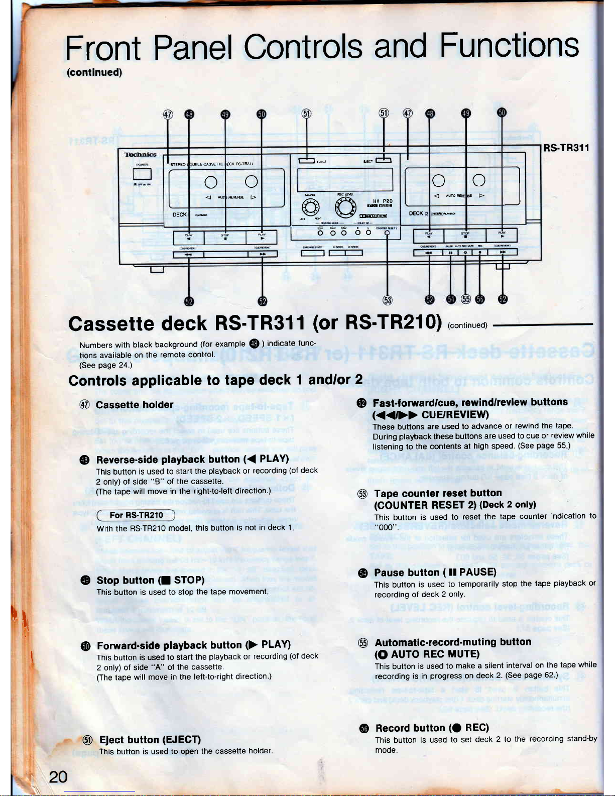
Cassette
deck
RS'TR31
1
(or
RS'TR2l0)
r"ontin,"or
Numbers
with
black
background
(for
example
@
)
indicate
tunc-
tions
available
on
the
remole control.
(See page
24.)
Controls
applicable
to
tape deck
1
andlor
2
@
Cassette
holder
@
@
Reverse-side
playback
button
({
PUVI
This button
is used to start
the
playback
or
recording
(of
deck
2 only) ol side
'18"
ol
the cassette.
(The
tape
will move
in the right-to-lelt
direction.)
@
For RS.TR210
With the RS-TR210
model, this
button
is not in deck
1
@
Stop
button
(I
STOP)
This
button
is
used
to stop the tape
movement
@
Fomard-side
playback
button
(>
PLAY)
This
button
is used to start
the
playback
or
recording
(of
deck
2 only) of
side
"A"
of the
cassette.
(The
tape
will move
in the
left{o-right
direction.)
@
Eject button
(EJECT)
This button is used
to open
the cassette
holder.
Fast-forwardlcue,
rewindlreview
buttons
(<<D>
CUE'REVIEW)
These buttons
are
used to
advance
or rewind
the tape.
During
playback
these
buttons
are used
to cue
or
review while
listening to
the contents
at
high
speed.
(See
page
55
)
Tape counter
reset
button
(COUNTER
RESET
2)
(Deck
2 onlY)
This button
is used
to
reset the
tape
counter
indication
to
"000".
@
Pause button
(
ll PAUSE)
This button
is
used
to
temporarily
stop
the
tape
playback
or
recording of
deck
2 onlY.
@
Automatic-record-muting
button
(O
AUTO
REC
MUTE)
This button
is used
to
make a silent
interval on
the tape
while
recording
is in
progress
on
deck
2.
(See
page
62.)
@
Record button
(O
REC)
This button
is used
to set
deck
2 to
the
recording
stand-by
mode.
RS.TR311
rf'
t
20
Page 21
llt!!
-t5
t!lll
lltIl
I!!ilr llllll
illlt llilr l llllt
llil!
ltIlil lillll
o ool+5
llllt
illrr
llllll
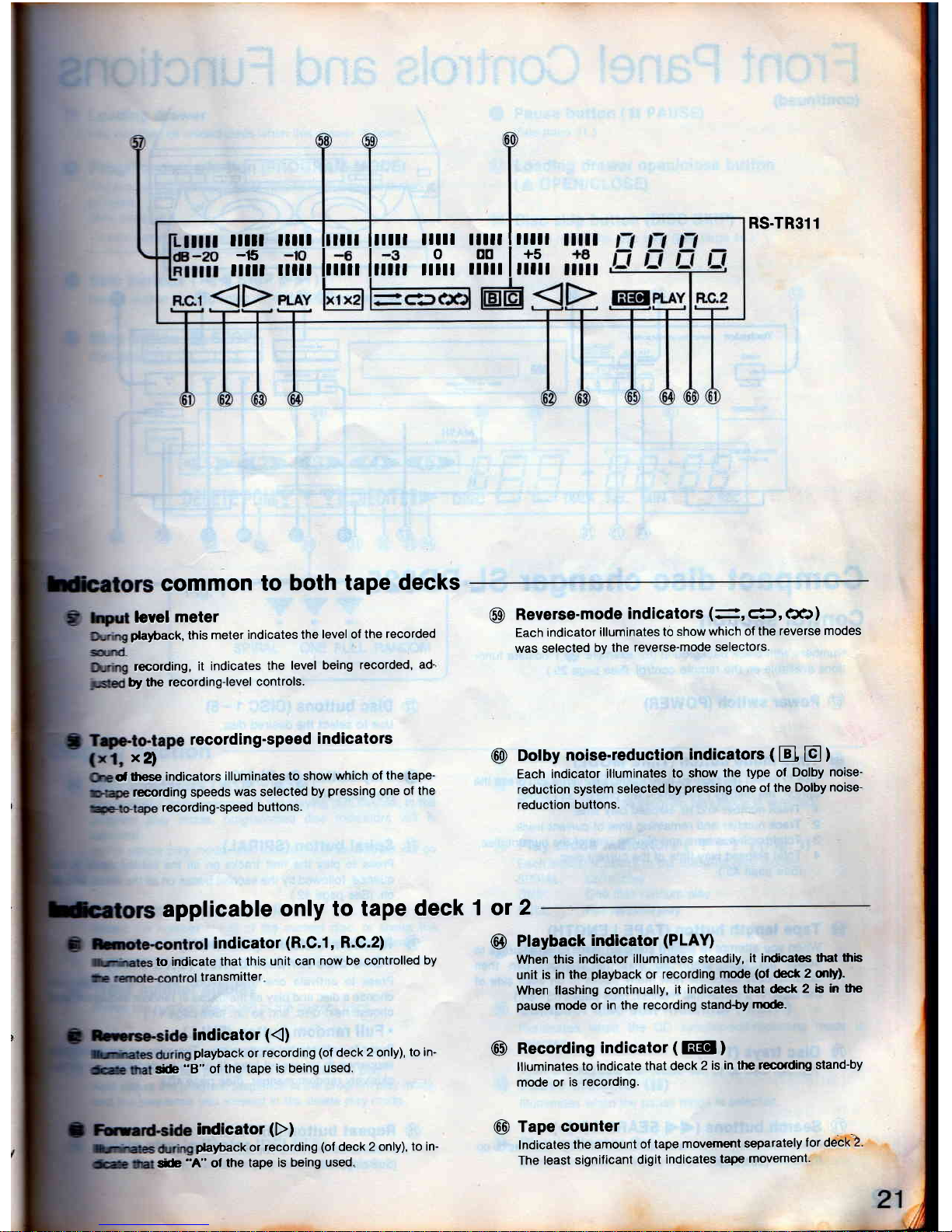
common
to
both tape
decks
level
meter
playtack,
this
meter
indicates the
level of the
recorded
recording,
it indicates
the
level being
recorded,
ad'
by the
recording-level
controls.
recording-speed
indicators
x!
d
tlese
indicators
illuminates to show
which
of the tape-
recording speeds
was
selected
by
pressing
one
of the
recording-speed
buttons.
RS.TR311
Reverse-mode
indicators
(-,
df
,
c:CJ
)
Each
indicator
illuminates to
show
which of the
reverse
modes
was selecled
by the
reverse-mode
selectors.
@
Dolby
noise-reduction
indicators
(
EI E )
Each
indicator
illuminates
to show
the
type ol
Dolby noise-
reduction
system
selected
by
pressing
one
ol lhe
Dolby noise-
reduction
buttons.
@
Ptayback
indicator
(PLAU
When this
indicator
illuminates steadily,
it indicates tlar
$b
unit
is in the
playback
or recording
mode
(of
deck
2 mly).
When
llashing
continually,
it indicates
that deck
2 b
in the
pause
mode or
in
the
recording stand'by
mode.
Recording
indicator
(
EEo
)
llluminates
to indicate
that deck
2 is
in
the
recording
stand-by
mode or
is
recording.
Tape
counter
lndicates
the amount
of tape
movement
separately
for deck
2.
The least
signiricant
digit
indicates
tape
movement.
@
applicable
only
to tape
deck
1 or
2
indicator
(R.C.l,
R.C.2)
to indicate
that this
unit can
now be controlled
by
transmitter
indicator
({)
playback
or
recording
(of
deck
2
only),
to in-
@
@
t*re
"8"
ol
the tape
is being
used.
indicator
(D)
p*ayback
or
recording
(of
deck
2 only),
to in-
tib
"A"
ol
the tape
is being used.
Page 22
Front Panel Controls
and
Functions
(continued)
ll
i
t
I
i
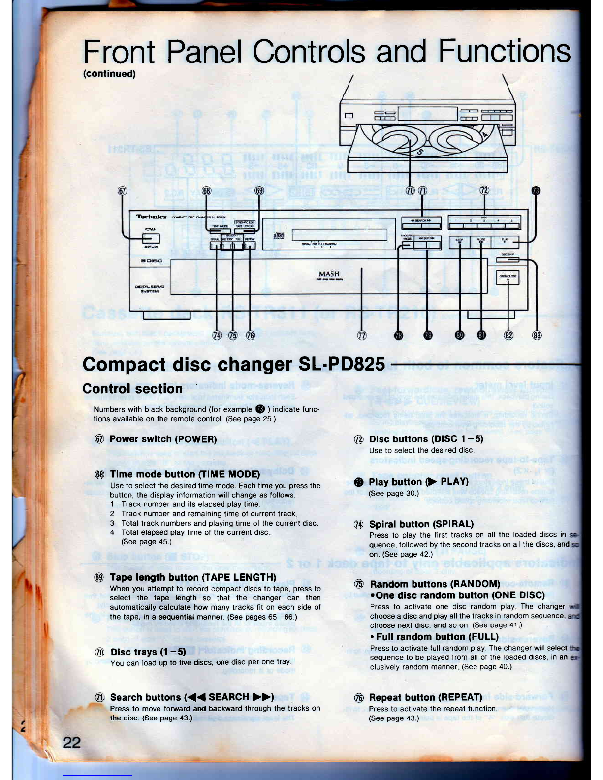
Compact
disc
changer
SL-PD825
Control section
Numbers with black background
(for
example
@
)
indicate
tunc-
tions available on
the remote
control.
(See
page
25.)
@
Power
switch
(POWER)
@
Time mode button
(IIME
MODE)
Use
to
select
the
desired time mode. Each time
you
press
the
button, the display information will
change
as follows.
1 Track number
and
its
elapsed
play
time.
2 frack number and remaining
time of
current
track
3
Total
track
numbers
and
playing
time of the current disc.
4 Total
elapsed
play
time of the current disc
(See
page
45.)
@
Disc buttons
(DISC
1-5)
Use to select
the desired
disc.
Tape
length button
(IAPE
LENGTH)
When
you
attempt to record compact
discs
to tape,
press
to
select the tape length
so that
the changer can then
automatically calculate how many
tracks
fit on each side of
the tape, in
a sequential
manner.
(See
pages
65-66.)
Disc trays
(1-5)
You
can
load up
to
five discs,
one disc
per
one
tray
Search buttons
(<<
SEARCH
>>)
Press to move forward and backward
through
the tracks on
the disc.
(See
page
43.)
Play button
()
PL1Y)
(See
page
30.)
Spiral button
(SPIRAL)
Press to
play
the
first tracks on
all the
loaded discs
in
quence,
followed by the second
tracks on
all the discs,
and
on.
(See
page
42.1
Random buttons
(RANDOM)
.One
disc
random button
(ONE
DISC)
Press to activate one
disc random
play
The changer
choose a
disc
and
play
all the tracks in
random
sequence,
choose
next disc, and so on.
(See
page
41
)
.
Full random
button
(FULL)
Press to activate
lull random
play.
The
changer
will
select
sequence to be
played
from all of the
loaded discs, in an
clusively
random manner
(See
page
40.)
Repeat
button
(REPEAT)
Press to activate
the repeat
function.
(See page
43.)
(D
@
6E
@
@
@
o
Tbchola
*rc,m
Page 23
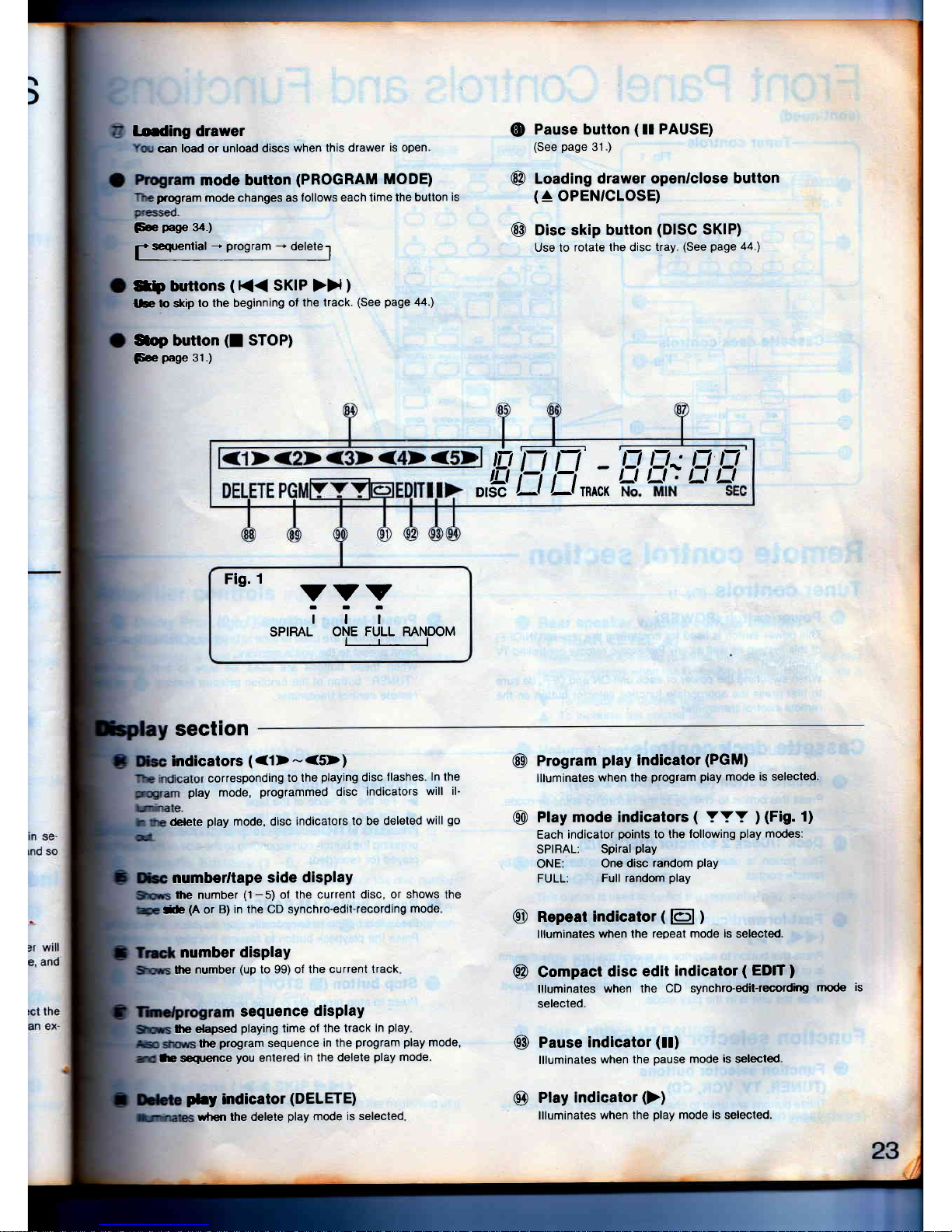
Loding drawer
can
load
or
unload discs
when lhis
drawer
is
open
mode button
(PROGRAM
MODE)
program
mode changes as
follows each time
the button
is
Fee
pagp
34.)
f
seqrential
-*
program
-t
deletel
Stp
bnrtlons
(
(<
SKIP
>>
)
lbto
skip
to the beginning
of
the track.
(See
page
44')
$op butlon
(I
STOP)
Fce
page
31.)
Pause button
(
ll
PAUSE)
(See
page
31
)
Loading
drawer openrclose
button
(
^
OPEN'CLOSE)
Disc skip button
(DISC
SKIP)
Use to
rotate the disc
tray.
(See
page
44.)
q)
@
@
IEi
EE
-
DISC
,-l
/-l glgX
EH;EE
Fio. 1
-
vvv
iTi
SPIRAL
ONE FULL RANDOM
lrl
section
Sndicators
(<1>-<5>)
corresponding
to the
playing
disc
flashes.
ln the
play
mode,
programmed
disc
indicators
will il-
(blete
play
mode, disc
indicators
to be deleted
will
go
@
numberltape
side display
the number
(1
-5)
ol the current
disc, or shows
Se
(A
or
B) in the CD synchro-edit-recording
mode
lhe
program
sequence
in the
program
play
mode,
@
@
@
@
number
display
lhe
number
(up
to 99) of
the current track
sequence
display
fie elapsed
playing
time
of the track
in
play
le sequence
you
entered
in
the
delete
play
mocle.
plry
indicator
(DELETE)
@
Program
play
indicator
(PGM)
llluminates
when the
program
play
mode is selected.
Play
mode indicators
(
YYY
)
(Fig.
1)
Each indicator
points
to the
following
play
modes:
SPIRAL:
Spiral
play
ONE:
One disc
random
play
FULL:
Full random
play
Repeat indicator
(
El
)
llluminates
when the
repeat mode is
selected.
Compact
disc edit
indicator
(
EDIT
)
llluminates
when the
CD synchro-edit-recordhg
mode
is
selected.
Pause
indicator
(!!)
llluminates
when the
pause
mode
is
selected.
Play
indicator
())
llluminates
when the
play
mode is
selected.
wtlen the delele
play
mode
is selected
Page 24
Front
Panel
Controls
and Functions
(continued)
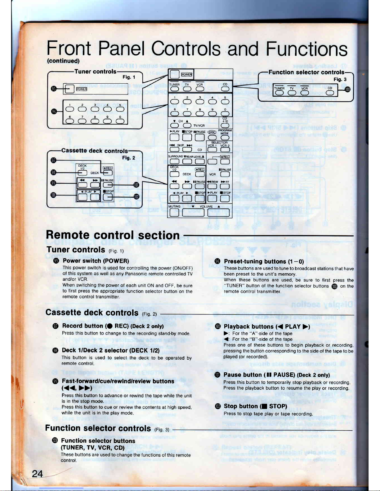
Remote
control
section
I
I
t.
L
t_
f
[;
Tuner
controls
rrig
rl
@
Power
switch
(POWER)
This
power
switch is
used ,or
controlling
the
power
(ON/OFF)
of
this system as
well as any
Panasonic remote
controlled
W
and/or VCR
When
switching
the
power
of each
unit ON and
OFF, be sure
to first
press
the appropriate
function
selector button on
the
remote
control transmitter
Cassette
deck
controls
rrig.
zl
@
Record
button
(O
ReCl
(Deck
2
only)
Press
this button
to change
to the recording
stand-by mode
@
Deck l/Deck
2
selector
(DECK
1/2)
This
button is used
to select the
deck to be
operated by
remote
control
@
Fast-forward/cue/rewind/review
buttons
(<<,
>>)
Press this
button to advance
or
rewind
the tape while
the unit
rl
is in
the stop mode.
F
Press this button
to cue or review
the contents at high speed,
while the
unit
is in
the
play
mode
Function
selector
controls
rrig
st
@
Function
setector
buttons
(TUNER,
TV, VCR,
CD)
These
buttons
are used
to change
the functions
of this
remote
control.
24_
-/
@
Preset-tuning
buttons
(1-0)
These
buttons are used
to tune to broadcast
stations that have
been
preset
to
the unit's memory.
When
these buttons are used,
be sure to first
press
the
"TUNER"
button of the
function
selector buttons
@
on
the
remote
control
transmitler.
@
Ptayback
buttons
(<
PLAY
>)
):
For the
"A"-side
of the tape
{:
For
the
"B"-side
of the tape
Press
one
of
these
buttons to begin
playback
or recording,
pressing
the button corresponding
to the
side of the tape to be
played
(or
recorded).
@
Pause
button
(
tt PAUSE)
(Deck
2 only)
Press
this button
to temporarily stop
playback
or
recording
Press
the
playback
button to resume
the
play
or
recording
@
Stop
button
(I
STOP)
Press to
stop tape
play
or tape recording.
Tuner controls
Fig.
1
[--lm
Function
selector controls-
Fis' 3
l'55
5 5p
,_4
n
frfJre|
TUNER TV VCR
-)
a-) al
CD
ffi
IOOOOOI
12345
OOOOO
67890
YcHA liio
(-J (_)
wrvce
l-
)
deck eanlro!
>PLAY
ISTOP
ttPAUsE
DDD
K<
SKIP >}I
;URROUNO
VREAR LEVELA
n-r-_)
---l-FEet
OO
1t2
l.REc
n
oecr
[--
I]C]C
DDI
!I
PAUSE
vcn
(---l
8fr
>PLAY
ISIOP
DD
15
V VOLUME A
Page 25
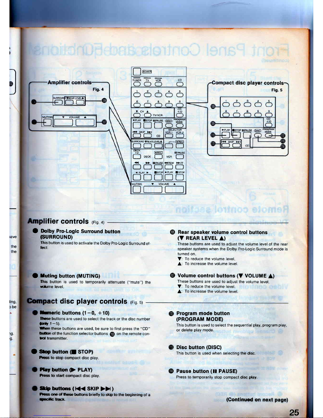
Iier
controls
rrig
ar
25
O
OolUy
Pro.Logic
Surround
button
(suRRouND)
This
butlon
is
used to activate
the Dolby
pro-Logic
Surround
ef-
lect.
O
luting
button
(MUTING)
Ihb
button is
used
to temporarily
attenuate
("mute")
the
Ellme level
@
Rear
speaker volume
control buttons
(V
REAR
LEVEL
A)
These buttons are used
to adjust the volume level
of the
rear
speaker
systems
when
the Dolby Pro-Logic
Surround mode is
turned
on
V:
To reduce
the volume level
A:
To increase
the volume level.
@
Volume
control buttons
(V
VOLUME
A)
These
buttons are used
to adjust
the volume
level
V:
To reduce
the volume level.
A:
To increase
the volume
level.
ling,
obe
19.
rg.
disc
player
Gontrols
reig
sl
hneric
buttons
(1-0,
+10)
rlge
buttons
are used to select
the track or the disc number
E,
1-5).
rmen
these
buttons are used, be
sure to
f irst
press
the
"CD"
lrr0on of
the function selector
buttons
@
on the remote con-
ffi transmitter.
O
*e bumon
(I
sroP)
kss to
slop compact
disc
play
Plry
button
(>
PLAI
Fess
to
start cornpact disc
play.
S
buttons
(
K<
SKIP
>>
)
hcss
qe
of lfe
buttons
briefly to skip to
the beginning
of a
T-cif
rElr
@
Program mode
button
(PROGRAM
MODE)
This button
is
used to select the sequential
play, program play,
or
delete
play
mode.
@
Disc
button
(DISC)
This
button
is
used when selecting the
disc.
@
Pause
button
(ll
PAUSE)
Press
to temporarily
stop compact disc
play.
!re
ct disc
player
controls
Fig.
5
TUNER
TV VCR
OOC] O
12345
OOOOO
67890
VCHA
l-ro
(l (l
wrvca
I(-
]<K
SK|P
)}r
CD
H
lglrlBu1E
@'T8J,
LJIJLJOO
;URFOUND
VBEAR
LEVEL'
ODC
r--l-FEar
OO
1t2
l.RECl
[---l
oecrl
[-)
OC-]O
<
PLAY
>
ISTOF
DDD
VCR
II PAUSE
O
<<BEW )}FF
OO
f]D
V VOLUME
A
(Gontinued
on
next
page)
Page 26
Front
Panel
Controls
and
Functions
(continued)
Remotg
control
sectioh
(continueo)
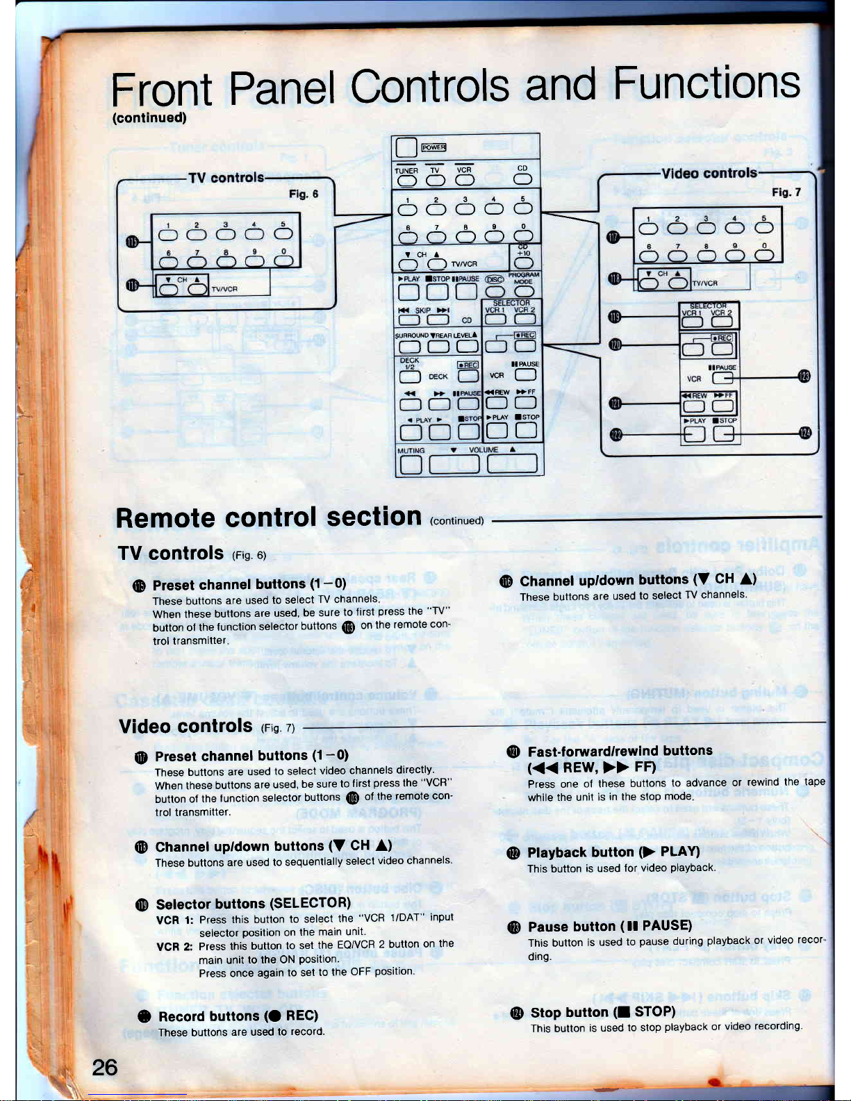
TV controls
rrig
ol
(D
Preset
channel
buttons
(1-0)
These
buttons
are used
to
select
TV channels
When
these
buttons
are used,
be sure
to first
press
the
"TV"
button
ol the
lunction
selector
buttons
@
on
the remote
con'
trol
transmitter
@
Channel
upldown
buttons
(V
CH
A)
These buttons
are
used
to selecl
TV channels'
!re
rUNEB
TV
VCR
OOO
CD
O
12345
CfOOOO
87890
+10
tcHl
(1
C-)
wrvcn
)uFRouND TREAR
tEvELA
ODC
OO
>PLAY
ISTOP
DD
II
PAUSE
vcn
(--l
Video
controls
rrig.
zl
@
Preset
channel
buttons
(1-0)
These
buttons
are
used
to select
video
channels
directly'
When
these
buttons
are used,
be sure
to
f irst
press
the
"VCR"
button
of
the
lunction
selector
buttons
(@ of
the
remote
con-
trol transmitter.
(D
Channel
upldown
buttons
(V
CH
A)
These
buttons
are used
to sequentially
select
video channels'
@
Selector
buttons
(SELECTOR)
VCR
1:
Press
this button
to select
the
"VCR
1/DAT"
input
seleclor
position
on
the
main
unit.
VCR
2:
Press
this
button
to set
the
EQ/VCR
2 button
on
the
main
unit
to the ON
Position.
Press
once
again
to set
to
the
OFF
position'
e
Record
buttons
(O
REC)
These buttons
are used
to
record.
@
Fast-forwardlrewind
buttons
(<<
REW,
>>
FF)
Press
one
of these
buttons
to advance
or
rewind the
tape
while
the unit
is
in the stop
mode
@
Playback
button
(>
PLAD
This button
is used
lor video
playback.
Pause
button
(
t!
PAUSE)
This button
is
used
to
pause
during
playback
or
video
recor'
ding.
Stop
button
(I
STOP)
This button
is used
to stop
playback
or
video
recording'
@
26
@
Page 27

fl spe.meRs
z
,-t-,
&\
-=-T-
*-fa
I
ir5666-o-'l
fr-T--El
r--r------------
:-E EEEET:I
I*-reEEre
---
I
_EE
T-r-T-rl'l'l
r
Mutual
Operations
Start the
sound
source.
SL-PD825
the
main
unit
1 Set
the
power
switch
of
each
unit
to ON.
The
power
lor the entire
syslem
can
therealter
be switched
(Xrl
and OFF
by using
the
power
switch
of the
tuner.
fforided
that the
power
cords
are connected
as on
page
8)
1t takes about
4 seconds
for the
initial
set up of
the compact
dsc
changer.
Please
wait
lor this
period
belore
proceeding
to
tte
next operation.
Select
the
"A"
andlor
"8"
speaker
system(s)
!o be
used.
When only one speaker
system
is connected,
no sound
will be
heard if both speaker
selectors
are
pressed
Set
the input selector
of the
graphic
equalizer
b
the
"SOURCE"
position.
4
Setect
the sound
source.
VCR
IIDAT: Press
this button
to listen to the
equipment
con'
nected
to the
"VCR
l/DAT" terminals.
TAPE:
Press
this button
to
listen to tapes.
CD:
Press
this
button to
listen to compact
discs-
TUNER:
Press
this button
to listen to
radio broadcasts-
PHONO:
Press this
button to
listen to
phono
discs.
C Start
the
sound
source.
O
Adiust
the
volume
level.
After
listening
is finished
Be sure
to
reduce
the volume
level, and switclt
OFF
the
power
from the
power
switch
of
the tuner.
Note:
The
input selection,
super
bass
setting'
muting settings
and
the Dolby
Pro-Logic
Surround
mode
will be
retained
(as
they
were
at the
time
when the
power
was switched
OFD
by
the
memory
back-up
Iunction.
(Continued
on
next
page)
Page 28

M
utual Ope
rations
(conrinued)
Headphones
(not
included)
Plug type:
'1l4
inch
phone plug
stereo type
From
the
main
unit
(continued)
,g^-,,9,o,.
Adjust the balance control.
To
adjust the tone
quality
To
adjust
the
leftlright sound
balance
BALANCE
.,,Q,o,,
To
emphasize
low
frequency sound
Press the super bass
button to boost
the super-low
frequency
range.
(fhe
indicator
will illuminate.)
Adjust the
low-frequency sound to
the
desired
tone
quality.
Adjust the
high-lrcquency sound
to
the desired
tone
quallty.
This will not adjust
the
speakers.
lefUright
volume balance
of the
rear
When listening through
headphones
Reduce
the
volume level, and connect the
headphones to
the head-
phones
jack.
ll
sound
from the speakers
is not wanted, set
the speaker selectors
("SPEAKERS")
to the
"OFF" position.
Set
the Dolby Pro-Logic
Surround
button to OFF.
Avoid listening lor
prolonged
periods
of time to
prevent
hearing
damage.
BALANCE
qlFr
E
+'-
-
-r
jffi6Ed
'=-
| l-l( )
-O-
O. O-
28
Page 29

65665
MUTING
D
From
the
remote
eontrol
To switch
each
componcnt'9
power
OFFION
Have
you
set
the
powor
srltdr-olrcfi
unlt
to
ON
?
1
Pr"""
the
"TUNER'button
2
Press
the
Power
switch.
(The
power
of each
unit
will be
switched
OFF')
in"
';srRNogY" indicator
("STANDBY")
on
the
tuner
will
il-
luminate,
and
the
indicators
ol all
other
units
will
switch
OFF'
To
restore
power
to
all components'
press
this switch
again'
To attenuate
the
volume
bvel
Press
the
muting
button.
MUTING
R
The volume
level
is attenuated
by
approx
20
dB
(1n0)
(Ihe
muting
indicator
on
the
amplifier
win
illmanate')
Press
once
again
to
resume
to
the
pIeuixls nolume
level'
Ohe
muting
indicator
on
the
amplifier
will
not
illuminate')
When
canceling
muting
at
the
main
unit,
tum
the
volume
on
the
amplifier
to
"-
-d8".
To adiust
the
volume
level
Use the
Yolume
control
buttons-
Page 30

Listening
to
Compact
Discs
-l
eress
the input
!
selector
on
the
amplifier
marked
,,cD,,.
$
r-oaa
the
disc(s)
on
the
disc
tray(s).
t.
il
T
i
I
l
I
30
\
Sequential
play
Sequential play
involves
playing
all
the five
discs on
the five-disc
tray
in
sequence
beginning
with
the first
track
on
the disc
al the
playing
position.
Have
you
perlormed
the
steps
1
-
3
(on gage
2Tl
ol
"Mutual
Operations"
?
Press
the
input
selector
on the
amplifier
mark.
ed
t'CD".
(Ihe
input
selector/volume
level
display
on the
amplifier
shows
"CD".)
This
step is
not necessary
when
using
the remote
conlrol.
Press
the loading
drawer
openlclose
button
to
open
the loading
drawer.
Load
the
disc(s)
on the
disc
trays(s).
Do
not load
3"
(8
cm)
and
5"
(12
cm)
discs
on the
same
disc
tray.
The
number (1
-
5)
on the
disc
tray
indicates
the
disc number.
Label
must f
upward
Press
the loading
drawer
open/close
button
again
to
close
the loading
drawer.
You
can
skip this
step by
pressing
the
play
button.
The
loading
drawer
will
be
closed
automatically
then
play
will
start.
Do not
attempt
to close
the
drawer
by hand.
Be
sure
to
press
this
button.
Press
the
disc
skip
button
to
select
the
desired
disc.
Press
the
ptay
button.
(Also
available
from
the remote
colrtrol.)
The
play
indicator
will illuminate
and
sequential
play
will
start.
The
disc indicator
corresponding
to
the
disc being
played
Ilashes.
number
in
play
Play
indicator Elapsed
The
changer
plays
all the
tracks
on
all the
discs
in
order
and
stops aulomatically
when
the last
track
on the
last
disc
finishes
playing.
The first
disc
will
be at
the
playing
position.
CAUTION:
Do
not
move
this
changer
with
a compact
disc inside
the unit.
lf
a
disc
comes
off
the
disc
tray, it might
be
scralched
or the
changer
might
become
incapable
of
playing.
Refer
to
page
76
before
moving
the
unit.
4
5
6
2
3
Carousel
After
loading
discs
on
the
two
disc
trays
at the lront
position,
press
the disc
skip button
(see
step
5) to
move
the carousel.
A
different
two
disc
trays
will
be at
the front
position.
Notes:
Do
not
touch
the
carousel
nor
the loading
drawer
while it
is
movrng.
Do
not
turn
the tray
lorcibly
by hand
because
it
may fail
to
operate
normally.
Pressing
this
button
will
move
the carousel
by one
position.
Disc
number
at the
playing
position
<1><2><3><4>
't-
':t
DSC
{
Page 31

TbdDI€
E
sL.PD825
To
exchange
discs
during
PlaY
A CD
in a tray
not
playing
at
the time
can
be exchanged
even
when
another
CD
is
Playing.
1
pr"""
the
loading
drawer
openlclose
button
to open
the
loading
drawer.
2
Press
the
disc
skip
button
to
move
the disc
trays
and
then
exchange
discs.
The carousel
will move
by one
position.
Pressing
again
moves
the carousel
in the opposite
direction
by two
disc
trays'
Press
the
loading
drawer
openlclose
button
to close
the
loading
drawer.
lf
you
play
a disc
with the
loading
drawer
open,
the changer
will stop
when the
last track
on the
current
disc
linishes
play-
lng.
3
To temporarily
stoP
PlaY
(Also
available
lrom
remote
control)
Press
the
Pause
button.
I-"-r*l
Lxl
\\\
\J
This switches
the
changer
to the
pause
mode,
and the
pause
in'
dicator illuminates
The disc
rotates
while the
changer
is in the
pause
mode.
Press the
play
button
to
resume
play.
To
stop
play
(Also
available
lrom
remote
control)
Press
the
stoP
button.
fhe
disc
will stop
rotating,
and
the display
will show
only
the
disc
number
at
the
Playing Position.
Page 32

{?
Listeni
to
Compact
Discs
1
Press
the
i
selector on the\ J
amplifier
marked
"cD".
Direct access
play
(continued)
,,\
t\r
\-;
\\
t,
Have
you performed
the steps
1
-3
(on page2Tlot
"Mutual
Operations"
?
K< SKIP >)l
Tbcini.s
,**ffi
tt
-
F-fr-m-fr-il
sElaElur
atDl
:
ffi
From
the
main
unit
Direct access
play
involves
starting
play
from a specific
track
on a
specif ic disc and
playing
all discs
on the
five-disc tray
in sequence.
I
I
Press
the
input selectoron
the amplilier
mark-
ed
"CD".
(fhe
input selector/volume
level
display
on the
amplifier
shows
"CD"
)
Z Press the desired disc button
(115).
For example:
To select disc
1,
press
the
l--r
button.
The selected
disc indicator
will flash.
lf
the disc only
is
selected,
play
of
all tradks on that disc
(begin-
ning with its first track) will begin
in
about
ten
seconds.
lf
a disc
is not
on the selected disc tray, the changer
plays
the
disc at the
next number.
Press the skip button to select the track
number.
For
example:
To
select the
gth
track,
press
the
))
button I
times.
lf
you pass
the desired track,
press
the
]<<
button to
return.
Play will
start
lrom the selected track
The changer will stop automatically
when the last track on the
last
disc
linishes
playing
ll
you play
a disc
with the loading drawer
open,
the changer
will
stop
when the
last track on
the current disc
finishes
play-
tng.
3
Track
number
32
J
Page 33

From
the
remote
control
lf
you
want to start
with the
disc
at the
phying
pctitim'
proceed
to
step 3.
!
I Prese the
"CD'button.
2 Press the
disc buttm.
3
Press the numerlc-httton
(1-O
lo select
the
disc.
lf
a disc
is not
on
the
Selected dsc
lJay,
the changer
plays
the
disc at the
next number.
ll
the
disc only
is
selected,
day
of all tracks
on that
disc
(begin'
ning with its
lirst
track)
will begin
in about ten seconds.
4 Press the
numerlc button
to speclly
tttc track.
Tracksl-S
Plesstheappropriatonumericbutton
$
- $
directly.
To
eelcct
a twod[th
brr*
number oYc]
10:
Press
the
I
button
to select the
"tens"
digit,
and then one
of the
3
$
buttons
to select
the
"units"
digit.
To
ccbcl
. trlck
numDcr such ae
3ll:
Press the
I
futton
three times
and then
I
Play
will start
from the s€lected
track.
The changor
wil! stop
automatically
when
the last fiack on
the
last dlsc
lttlshes
playing.
12345
ooooo
s
*EdlElElE
Aeassg
t6
7
A I0
oooo6)
\t9
Page 34

Listening
to
Compact
Discs
(con,nued)
'l
Press
the
input
I
selector on the
amplilier
marked
ttcDtt.
6
n"p""t
steps 3,4
and 5
as desired.
-Dtsc-
4.ry-
Tbcnnie
ffsBreR$.PM
,**ffi
tt
tt
-
fi-fr-fi-fi-il
ProEram
play
You
can
program
up to 32 selections
from the
five discs in any
order as
you
desire.
Have
you
performed
the steps
1
-
3
(on
gage
271ol
"Mutual
Operations"
?
From
the
main
unit
I
I Press the input selector
on the amplilier
mark.
ed
"CD".
(fhe
input
selector/volume
level display on
the amplifier
shows
"CD".)
Z !n the stop mode,
press
the
program
mode but-
ton to select the
program play
mode
(PGM).
The
display
changes in the
lollowing
way each
time the button
is
pressed.
(OFfl-PGM-DELETE
r_l
For example:
To select
the
gth
track,
press
the
)H
button
9
times.
Specified
lrack
number
12<3>45
PGM.
.
.
a
)
D(tC
D
-J*
no.
5
Press the
program
mode button.
Program order
12<3>45
PGM. . .
a
)
rxic
qi
-,
nH No.
To
enter track
I successively
1
Press the
)}l
button.
2 Press the
K{
button.
3 Press the
program
mode button
at this time.
Repeat steps 3,
4 and 5 until
you
have com'
pleted
the desired
entry.
lf
you
enter
non-existing disc(s)
or track(s)
soon
alter the
loading drawer is closed or
when
it is
open,
the corresponding
indicator
illuminates and
the entry
is included
in
the
count.
In
the
play
mode, the
changer
will cancel
the non-existing
entry
and
play
the subsequent
programmed
disc
or track
ll
you
attempt
a 33rd
selection,
the
-f
(full)
indlcation
will
be
displayed.
Press
the
play
button
to start
play.
To enter additional
selections
during
play,
repeat
steps
3,
4
and 5.
Play the changer
with the
loading drawer
closed.
While the loading drawer
is
open,
if next
programmed
selec-
tion
is in
one
of lhe other
discs,
the changer
will stop
after the
current
track finishes
playing
3
Press
the desired
disc button
(1-5).^
For example:
To
select
the 3rd disc,
press
the
rl
button
Specified
disc
number
1 2 <3> 4 s
7Dl !
pGM.
- -
o,Sa,/
/Lr*,**o.
,
fne
r9L
indication shows that all the
tracks on the
disc are
selected. Skip steps
4 and 5
iI
you
want to enter only
the disc
number.
Press the skip
button
to select the
track
number.
6
7
4
u
Page 35

4aE83s
O
D
Ft 2 3
4
5
I
.]OOOO
vgsssS
Repeat
steps
3,
4
and
5 as
desired.
From
the
remote
control
1
Pr"""
the
"CD"
button'
6
Repeat
steps
3,
4 and
5
until
you have
com'
lf
you
attempt
a 33rd
selection,
the
-
[
(full)
indication
will
be
disPlaYed.
7
Press
the
play
button
to
start
play'
To
enter
additional
selections
during
play' repeat
steps
3'
4
and
5,
Play
the
changer
with
the
loading
drawer
closed-
wnit"
tn"
loading
drawer
is open,
il
next
prog-rarnmed
selec-
tion
is
in
one
ol
the
other
discs'
the
changel
will
stQ
after
the
current
track
finishes
PlaYing'
2
ln the
stop
mode,
press the
program
mode
but'
ton
to
select
the
program
ptay mode
(PGM) on
the
main
unit.
Skip
to
step
5
if
the
disc
number
display
shows
the
desired
disc
number.
3
Press
the
disc
button'
4
Press
the
numeric
button
6
-
6
to
specifY
the
disc.
Step
5
is
not
necessary
if selecting
the
disc
only'
5
Press
the
numeric
button
to
specify
the
track'
To
program more
than
one
track
from
the
same
disc
such
as
3,
5,
and
1
in that
order:
Pt"..tn" 3
3,ano
A
buttons'
To
program
the
same
track
more
than
one
time'
press
the
nr."ri"
button
the
number
of
times
the
track
is
to
be
pro-
gram.
io select
a
two-diglt
track
number
over
0:
pi"..
tn"
I
Outton
to select
the
"tens" digit'
and
then
one
li
tn"
S
--
$
buttons
to
select
the
"units" digit'
To selecl
a
track
number
such
as
30:
o
Press
the
I
button
three
times
and
ther o
35
Page 36

Listening
to
Compact
Discs
(conrinued)
SL.PD825
Program
play
(continued)
This
function
is also
available
from
the
remote
control'
Follow
the
procedure described
below.
To
resume
sequential
mode
during
program
play
1
Pt""t
the
stop
button.
2
Press
the
program
mode
button
twice'
3
Press
the
PlaY
button.
The changer
still
has
the
program in its
memory
36
To clear
the
entire
Program
Press
the
stoP
button.
f"-;l
LIJ
D
The
display
will
indicate
as below.
Turning
olf the
power will also
clear
all
programmed
from
memory.
Press
once
in the stop
mode
or
twice
during
play
This clears
all
programmed selections
lrom
memory'
L
TbchDb
ffsmwF$ffi
_"*r
ffiF
:E:-1
I I *[*Eu*ff
!#
[-fr-ffi-fr-il
12345
PGM.
. .
,."/
tl*-.".11
Page 37

1
Press the
input
I
selector
on
the
amplifier
marked
*cD'.
SL.PD825
Repeat
stePs
3,
4
and
5
as desired.
4r%
-Dtsc-
=
=ffic
Delete
play
Have
you performed
the steps
I
-3
(on
page
27) ol
"Mutual
Operations"
?
From the
main unit
You can select
up to 32
selections
that
you
do
not want to
hear
and
put
them
in the
changer's
memory.
Then
yol
can enjoy
sequential,
full
random, or one
disc
random
play
o,
only
your
lavorite
tracks.
Press the
input selectoron
the
amplifier
mark'
ed
"CD".
(The
input selector/volume
level display
on the
amplifier
shows
"CD".)
ln
the
stop
mode,
press
the
program
mode
but'
ton
to select
the delete
play
mode
(DELETE).
Press
the
program
mode button.
Order
you
have entered
Repeat steps
3, 4 and
5 until
you
have com'
pleted
the desired
entry.
lf
you
enter
non-existing
disc(s)
or
track(s) soon
after
the
loading drawer
is closed or
when
it is open, the
corresponding
indicator
illuminates
and
the entry
is included
in the count.
ln
the
play
mode, the
changer
will cancel
the
non-existing
entry
and
play
lhe
subsequent
disc
or track.
lf
you
attempt
a 33rd selection,
the
-f
(full)
indication
will
be displayed.
Press
to start
PlaY.
To activate
sequential
play,
press
the
play
bution.
To activate
full random
play,
press
the
full random
button.
To aclivate
one
disc
random
play, press
the one disc
random
button.
To enter
additional
selections
to be
deleted
during
play,
repeat
steps
3,
4 and 5
ll
you
play
a disc
with the
loading drawer
open, the
changer
will
stop
when the
last track on
the current
<lisc
finishes
play-
tng.
5
6
2
3
Press the
disc butlon
(1-5).
For example:
To delete
the 3rd
disc,
press
the
A
ortton.
Specified
disc
number
<1><2>
3
<4D<Ili>
Ji-i t !
DELETE
"d
l-l
L
*,,
no.
,
ne
flL
indication shows
that all
the tracks
on the disc
are
selected.
Skip steps
4 and 5
if
you
want to delete
all the tracks
on
the disc.
Press
the
skip
button
to
select
the track
number.
For example:
To
select
the 9th
track,
press
the
>>
button 9
times.
Specified
track
number
<1><2><3D<4D<5>
_-7
t-i
DELETE
-
o,5A'
-/r*r*
*o.
7
4
(Continued
on
next
Page)
37
Page 38

Listening
to
Compact
Discs
(con,,nued)
6
3;r$,.
and 5
as
desired.
4a68at
\
s
Ft 2 s 15
AOOOOO
Srlo t 6
9 o
"'sE
Dgletg
play
(continuect)
From the
remote
control
1
Pr"ra the
"CD"
button.
Z
!n the stop
mode,
press
the
program
mode but'
'
ton
to select
the
delete
play
mode
(DELEfq
on the
main unit.
Skip to step
5 if the
disc number
display
shows
the
disc
number
you
want to delete.
5
Press the
disc
button.
4
Press the
numeric
button
O
-
5
,o
specify
the
disc.
Step
5
is not
necessary
il selecting
the
disc
only.
C
Press the
numeric button
to
specify
the
track.
To delete
more than one track
from
the same
disc such
as 3,
5, and
1 in that order:
Piesstne
$
, $,ano
3
brtton..
To delete
the same
track
more than
one
time'
press
the
numeric button
the
number of times
the
track
is to be deleted.
To select
a twodlglt track
number
over
10:
Press the
I
button to select
the
"tens" digit,
and
then one
of the
|
$
buttons
to selecl
the
"units"
digit.
To solect
a track
number such
as 30:
o
Press the
I button three
times
and lhen
o
Repeat
steps
3,
4 and
5
until
you
have com'
pleted
the
desired
entry.
lf
you
enter
non-existing
disc(s)
or
track(s)
soon
after
the
loading
drawer
is closed
or
when
it is open,
the
corresponding
indicator
illuminates
and
the entry
is included
in the
count'
ln
the
play
mode,
the
changer
will cancel
the
non-existing
entry
and
play
the subsequent
disc
or
track.
lf
you
attempt
a 33rd
selection,
the
-
f
(full)
indication
will
be
displayed.
7 Press
the
play
button
to
start
ptay.
To enler
additional
selections
to be deleted
during
play'
repeat
steps
3,
4 and 5.
ll
you play
a disc
with the
loading
drawer open,
the
changer
will stop
when lhe
last track
on
the current
disc
finishes
play-
tng.
6
Page 39

To
resume
sequential,do
during
play
(Alco
erellebtr lrom
rcnroto
coolnle
.,,..',
1 Pr"""
the
stop
button.
Z Press
the
program
modo
bu[lon.
J Press
the
play
button.
The
changer
still has
the selectom
to be
deleted in
its
mqnory.
To
clear
all
the
selections to
be deleted
(Alco
evelleble lrom
rerno0r
Gofiol)
Press
the
stop
button.
The
display
will indicate
as below.
<l><ilD<3D<4><5>
t
DEIEIE ,""'
n
Us
n
u
tL,
Press
once in
the stop mode
or twice during
play.
This
clears all
the selections
to be deleted from memory.
Turning
off the
power
will
also
clear all the
selectirrs
to be deleted
lrom memory.
39
'-l
Page 40

Listening
to
Compact
Discs
(con,inued)
sL.PD825
:
Tbc.bnl6
E
@
Random
play
Have
you perlormed
the steps
1
-
3
(on
page
271ol
"Mutual
Operations"
?
Full
random
play
The changer
will automatically select
the sequence
ol
selections
to be
played
from all of the loaded discs
in an
exclusively
random
manner
Press
the
lull random button.
FULL
[_^_[
\\\
\,
The
play
mode indicator
points
to
FULL and
full random
play
will
start.
;<3><4><5>
-7
-r
n'n t
--v
to,5
i*o
L-;krJ"
<'t><2><3><4><5>
fl*il
m
The changer
will randomly choose a track within
a randomly
selected disc. Once the
player
has
played
the selected
track, it will
chOose
a disc then a track
randomly again, excluding
the tracks
already
played.
ln delete
play
mode, the changer will choose
a disc
and track ex-
cluding the selections
to be
deleted.
The changer
will stop automatica$,
riE l all the tracks
on all the
loaded discs
have been
played.
Play the
changer with the
loading drawer clced.
While the
loading drawer
is
open,
il netd
track is in one
of the other
discs, the changer
will stop
after the current
track
finishes
playing.
Press
the
fu!!
random button
agnin
to cance.l
full
random
play
mode.
The FULL
play
mode indicator will
go
otrt
The changer
will
return
to
sequential
play
mode
from the current
track on the
currenl disc
which is
playing.
Page 41

F
of,
YIt-ly
SL.PD825
One
disc
random play
The
changer
will
randomly
play
all
tho
tracls
otr
a randomly
selected
disc.
Press
the
one
dlsc
randonr
builm.
ONE
DISC
nfl
\\\
\J
Th.e
play
mode
indicator points
to
Ot{E
and
one
disc random play
will
gtart.
The.changer
wiil
stop
automaticafiy
when
ail
the
tracks
on
ail
the
loaded
discs
have
been
played.
Play
the
changer
with
the
loading
drawer
closed.
While
the
loading
drawer
is
open,
the
changer
wilt
stop
after
the
current
disc
finishes playing.
Press
the
one
disc
random
button
again
to
cancel
one
disc
random play
mode.
The
ONE
play
mode
indicator
will
go
out.
The
changer
will
return
to
sequential play
mode
from
the
current
track
on
the
current
disc
which
has
been
playing.
<i><2><s><Dlq{t
q'
t n
.Y.
>
#
lu*.
n.n
t
u.u t
l{1{
SEC
*'.LL
*
The.changer
will
randomly
choose
a
disc
and
play
all
tracks
in
a
random
order.
Then
it will
choose
a new
disc rand-omty,
excluding
the
discs
already played,
and
play
all
tracks
in
a random
order.
ln
delete
play
mode,
the
changer
will
choose
a
disc
and
track
ex_
cluding
the
selections
to
be
deleted.
41
Page 42

Listening
to Compact
Discs
(con,inued)
sL.PD825
@
.I-l
Spiral
play
The
changer
plays
the
first
tracks
on all the
loaded
discs in
se-
quence,
followed
by
the
second tracks
on all
the
discs, and
so on.
Have
you performed
the
steps
1
-
3
(on page
2ll ol
"Mutual
Operations"
?
Press
the
spiral
button.
When
the disc
with less number
of tracks fin{sfies
playing,
that
disc
will
be
skipped
and the
changer will
cqttitue
playing
with
the
other
discs having
the
tracks not
played
yet.
The
changer
will
stop
automatklally
when
all the tracks
on
all the
loaded
discs have
been
played,
Play the
changer with
the loading
dm
clced.
While the loading
drawer is
open, ftre
changer will
stop after the
current track finishes
playing.
Press
the
spiral
button
ag.in
tocancel
spiral
play
mode.
The
spiral
play
mode indicator
will
go
dn. The
changer will return
to sequential
play
mode
from
the current
track on the current
disc
which
has
been
playing.
The
play
mode indicator
points
to
with
the first
track
on the
disc
at
spiral
play
will
begin
position.
I
gML
ONE FUU BANlw
!r[<z><s><4><(5>
t
Y- >"*'
I n'n t
i u.u t
I
rMcx MtN sEc
42
Page 43

"fll"ltrlY
:
E
sre
E
Repeat
function
Search
function
You can use this
function
in all
play
modes
the
repeat
button
beloro
or
during
play-
The
repeat
indicator
will illuminate.
You
can search
rapidly
forward
or
backward
on the
disc
for
specific
sections.
ln the
play
or
pause
mode,
press
and
hold
one of
the search
but-
tons.
Release
the button
when
you
reach desired
point.
}}
l-
: You can search
foruvard.
{<
l-l
: You can
search
backward.
You can
search
slowly
at
first
and
then
rapidly
if the
button
is held
down
for more
than
about
three
seconds.
sL-PD82s
ln
sequential
play
mode:
All
tracks
of all
discs will be
played
repeatedly.
ln
program
play
mode:
The
changer
plays
only
the
programmed
selections
in the
pro-
grammed
sequence
repeatedly
ln
delete
play
mode:
The changer
plays
the Ciscs
and
tracks
excluding
the selections
to
be
deleted
repeatedly.
ln random
play
mode:
When
the changer
has
played
all
the tracks
on
all the
loaded
discs'
it will select
a
new
random sequence
and
play
repeatedly.
The se'
quence
diflers
each
time.
ln spiral
play
mode:
The
changer
plays
all tracks
of all
discs
repeatedly
in the
sequence
of spiral
play.
Press
the
repeat
button
again
to
cancel
repeat
mode.
The
repeat
indicator
will
go
out.
ln the
play
mode,
the sound
level decreases
by
12 dB
(1/4).
ln the
pause
mode, no sound
is heard.
ln sequentlal
play
mode:
You
can search
forward
over discs
and backward
within the cur-
rent disc.
ln other
play
modes:
You can
search
forward
or backward
only
within the
current
track'
Page 44

Listening
to
compact
Discs
(con,inuee
sL.PD825
ffi
fi-fi-fi--fr-i
Skip
function
To
skip
discs
You
can
use
this function
in
stop
mode,
sequential
play,
one
disc
random
play
mode
and
delete
play.
Press
the
disc
skip
button
to rotate
the
disc
tray.
ln
stop
mode:
When
the loading
drawer
is
closed,
pressang
the
disc
skip
button
changes
the
disc
tray
to the
nent
one-
When
the
loading
drawer
is
open,
pressirg
the
disc
skip
button
moves
the
carousel
by two
disc
trays.
In
play
mode:
When
the loading
drawer
is
closed,
pressirB
the
disc
skip
button
changes
the
disc
tray
to the
next
one
and
the changer
continues
to
play.
When
the loading
drawer
is
open,
pressitg
the
disc
skip biJtton
moves
the
disc
tray
to
the next
one.
pressing
again moves
lhe
carousel
in
the
opposite
direction
so that
you
can
change
all
discs
except
the
one
being
played.
To
skip
tracks
(Also
avallable
trom
remote
control)
Press
either
skip
button
until
you
reach
the
desired
track.
)l:
You
can
skip
fonrvard.
l{{: You
can
skip
backward.
ln
the
program
play
mode,
you
can
skip only
within
the
programm_
ed
tracks.
ln
the
delete
play
mode,
you
can
skip
tracks
excluding
the
tracks
to
be
deleted.
ln random play
mode:
))
: You
can
skip
to the
beginning
of
a next
track in
random
man-
ner.
l({:
You
can
skip
to the
beginning
of the
current
track.
ln
spiral
play
mode:
))
:
You
can
skip
to the
beginning
of a
track
on next
disc.
l{{:
You
can
skip
to
the beginning
of a
current
track.
You
can
also
skip
tracks
when
the changer
is
in
the
pause
mode
The
changer
skips
to the
tracks
selected
and remains
in
the
pause
mode.
ln
sequential/programldebte
play
mode:
))l
: You
can
skip
as
many
lracks
as the
number
of
times
you
press
the
button.
J{{:
You
can
skip
to
the
beginning
of
the
track
being
played.
lf
this
button
is
pressed
again
quickly,
you
can
skip
to
the
beginning
ol the
previous
track.
Remember
that
in
a
backward
skip,
lhe
current
track
is
in_
cluded
in
the
count.
4
Page 45

ffl*ElMi
.lf,l
:
fbtbnb
E
@
sL.PD825
Time mode selection
Press the
time
mode button
in the
play
or
pause
mode.
The information
will
change
(as
described
below) each
time
you
press
the button.
ln the following example,
the sth disc,
with
11
tracks,
45 min. and
56 sec.,
is
playing
at a
point
0 min. and 21
sec. after the beginning
of track 5.
v
\
I
The track
number and
its
elapsed
time of the current track
(normal
display)
<1><2><3><4><5D
f f n.1 t
t o,J
J,ro
uri tr
,'r.
<1D<2D<3><4><(5Df
f Lt.
tE
t J
:',-
.k
'-f,.
I
and
playing
<1><2><3><4><DE
I I
Li5.5E
) ot6d
I
l
nrcr
nn
- -stc
+
rema n ng time
!n all
play
modes:
When,,track
number 21 or
greater
is
playing,
display
2
shows
Display 3
changes to
display 1
while
you
are
pressing
one
of the
search
buttons.
ln
program
play
mode:
Display 4 shows
the
programmed
disc
and/or track number,
and
program
order.
While
you
are
pressing
the search
button, display
4 changes
to
display
1.
ln
delste
play
mode:
Display 4 shows
"-:-".
While
you
are
pressing
the search
button, display 4 changes to
display 1.
ln random and splral
play
mode:
Display
4 shows
"-:-".
While
you
are
pressing
the
search button,
display
4 changes
to
display
1.
ln the CD
synchrcodlt-recordlng
mode:
Display 4 shows
the
running time
of each
side of
the tape
When
you
stop
playing
and
play
again,
the display
will
return to
display
1.
2 Track number
and
ol
the
current track.
3 Total
numbers ol tracks
time
of the
current
disc
l
iril
Fk
\
+
the currenl
+
4 Total elapsed
play
time
of
45
Page 46

Listening
to Radio
Broadcasts
-l
Press
the
input
!
selector on the
amplilier
marked
'TUNER".
3
Tune
to the desired
broadcerf
lV
Dowltl
Press
to change the frequenca
dorrnward.
Fp
Al Press to
change the frequency
uprmrd.
o
Automatlc
iunlng
Press
the
button. When
the freqrenGy
indication
begins
to
change, release
the
button
(a
br@dcasting
station will
be
selected
automatically).
Repeat lhb
operation
until the
desired station
is found.
o
Manual
tunlng
Press
the
button momentarily
(frequency
will
change
edch
time the
button is
pressed),
and tune !o
the desired frequen-
cies.
Note:
lf
the
power
supply of the compact
disc changer has been left
on,
turn
off the
power
supply
of the compact disc changer.
2
f1
FM BAND AM
laT
tl
M
an Ual
tUnef
OpefatiOn
(ro
risren
ro broadcasts by
usins rhe runins butons)
Have
you perlormed
the steps I
-3
(on gage27)ot
"Mutual
Operations"
?
Press
the input
selector on
the amplifier mark.
ed
"TUNER".
(Ihe
input
selector/volume
level
display on
the amplilier
shows
"TUNER".)
Press
tho
"FM"
ot
"AM"
button.
lf
noise
is
excessive
in
Press
the
FM
mode
selector.
the FM
mode
The
sound
will then
be heard in
monaural
and the FM
stereo
in-
dicator will
noi illuminate.
lt
the broaclcast
signal is weak,
or
il
there is
a large
amount
of interference,
sounds can be heard more
clearly.
Page 47

1
Press
the input
I
selector
on the
amplifier
marked
"TUNER".
6
3,:?:"1
through
5.
4 Press
the memory
button momentarily.
([he
memory
indicator will illuminate.)
slqso qrytz
lod(
FM
EB
/
,,.P]
!-s^NB
5
Memory
indicator
To
cancel the
agarn.
memory lunction,
press
the
memory
button
Select the desired
"CHANNEL".
To
deslgnate channels
1-9:
Press the appropriate
(1
-9)
preset{uning
button.
To
designate channels 1O-24;,
O
Press the button for the
"tens"
digit
(l
or 2).
@
Press the button lor
the
"units"
digit
(1
-0)
within 2
seconds after
pressing
the
first
button.
lf the interval between
pressing
the first button and
pressing
the second button is more
than about 2 seconds, the
setting
may not
be made correctly. lf
this happens, make
the setting
once again
(following
step 4).
Repeat
steps 2
through
5 to make
additional
memory
presettings;
for later
retelence,
note
the
presettings
in the
station memory lile
on
pages
tt8
and 49.
Note:
lf
a
new
broadcast station is
preset
into
a channel, the broadcast
station
which
was
previously
entered in that
channel
will
be
automatically erased.
6
f1
FM BANo AM
zaT
tl
34567890
Memory
presettings
You can
program
24 FMIAM radio
broadcast
stations into memory,
so that any desired
station may be
selected by simply touching
one
or two buttons.
(See pages
48-49.)
Haue
you perlormed
the steps 1-3(on
page2nol
"Mutual
Operations"
?
I
! Press
the input
selector on the amplifier
mark.
Ed
"TUNER".
(Ihe
input
selector/volume level
display on
the amplifier
shows
"TUNEB".)
Z
Press
the
"FM"
or
*AM'button.
J
Tune
to the desired
broadcast.
It
powitl
Press
lo change the lrequency
downward.
IuFAI
Press to change
the
frequency
upward.
.
Automatlc
tuning
Press
the button.
When
the lrequency indication
begins
to
change, release
the
button
(a
broadcasting
station will
be
selected
automatically). Repeat
this operation
until the
desired
staiion is found.
.
ilanual
tuning
Press
the
button momentarily
(frequency
will
change each
time
the
butlon is
pressed),
and tune
to the desired
frequen-
cres.
Page 48

Listening
to
Radio
Broadcasts
(con,nued)
1
Press
the
input
I
selector
on
the
amplifier
marked
..TUNER".
sT.K50
I
I
1
t
r
dl
]
'\
.{
r
I
t
f
t
i.
-*
+
t
I
I
I
M
e m
ory
t
u n
e r
ope
rat
i
o n
(to
risten
to broadcast
stations
preset
into
memory)
H-ave
you
performed
the
steps
1
-3
(on
page2Tlot
"Mutual Operations,,and
the
steps
1-'e
1on
page
471ol
"Memory
presettings',
?
From
the
main
unit
1234567890
r-T-r-rl--l
--r--I-.rr-l
I
I
Presl
the
input
selector
on
the
amplifier
mark.
ed
"TUNER,,.
(The
input
selector/volume
level
display
on the
amptjtier
shows "TUNER,'.)
Z
Select
the
desired.,CHANNEL,.
To
designate
channels
1-9:
Press
the
appropriate
(1
-9)
preset-tuning
button
To
designate
channels
1O-21:,
!,1
Press
the
button
for
the
,,tens"
digit
(.1
or
2).
(2
Press
the
button
for
the,,units';
digit
(1
_0)
within
2
seconds
after
pressing
the Iirst
button
lf
the
interval
between
pressing
the
firsl
button
and
pressing
the
second
button
is
more
than
about
2 seconds,
the
setting
may
not
be made
correcily.
lf
this happens,
repeat
the
setting
procedure
once
again
t
r
*
e
t
l.'
I
i
I
I
i
n.
.i
il
il
il
i
it,
!t.
ai
I
.l
Station
Memory
File
(Use
this
file
to record your
memory
selections.)
lf
noise
Press
the
is
excessive
in
FM
mode
selector.
the
FM
mode
The
sound
will
then
be
heard
in
monaural
and
the
FM
stereo
in_
dicator
will
not
illuminate
lf
the
broadcast
signal
is
weak,
or if
there
is
a large
amount
of tnterference,
sounds
can
be
heard
more
clearly.
Note:
lf
the
power
supply
of
the
compact
disc
changer
has
been
left
on,
turn
off
the
power
supply
of the
compact
disc
changer.
ch.
1
ch.
2
ch.3
ch.
t0
ch.
5
ch. 6
ch.
7
ch.
8
ch. 9
ch.
10
ch.
11
ch. 12
ch.'13
ch.
la
ch.
15
ch.
16
ch.
17
ch. 18
ch.
19
ch. 20
ch.
2l
ch.
X2
ch.
23
ch. 2tl
Page 49

ffidlBlm
Ote86s
1e
r I 9
o
From
the remote control
1 Pr"""
the
"TUNER"
button. Z Select the desired
"CHANNEL".
To deslgnate channels
1-9:
Press the appropriate
(1
-9)
preset-tuning
button.
To deslgnate channels 1O-21:
Q
Press the button for the
"tens"
digit
(1
or 2).
@
Press the button
for the
"units"
digit
(1
-0)
within 2
seconds after
pressing
the lirst button.
lf the interval between
pressing
the
first
button
and
pressing
the second button
is more than about 2 seconds,
the
setting
may
not be made correctly. lf this
happens, repeat the setting
procedure
once
again.
Back-up memory
The
back-up
function
maintains the
preset
memory and the most-
recent memory
(see
below)
when
the
power
is
switched OFF,
in
the
event of a
power
lailure, or il the
power
cord
is
disconnected.
The memory will
be
maintained lor as long as approximately one
month.
Mosi-recenl memory
The most-recent memory system
"remembers"
the broadcast sta-
tion last tuned
to
when the
unit
was
switched
OFF. That station will
be
automatically
tuned
to when the
power
is switched ON.
lf frequency
prosettings
are
accldenttll, crtscd
Make the frequency
presettings (on page
47)
mce
aoain.
The
power
cord should
remain
connected
for
one
hour
or
more
lor
the
memory back-up to be effective.
49
Station
Memory File
(Use
thls
llle lo
record
your
memory
selections.)
.rL I clu 2 clt. t clu
tt
arL
5 ch. 6 ch.
7
ch.
E ch.0 ch.
10
ch. 11 ch.'12
c$. 13
ch.
la
crL
15 clL
lC
ci.
t7
ch. 18 ch. 10
ch.
2il1 cft.
21 ch. Al ch. 23 clt.21
Page 50

Listening
to
Tapes
Either normal,
CrOz or
metal
type
cassettes can be used
I
Press
the input
I
selector
on the
amplifier
marked
..TAPE'-
2
3
oo
oE( 1
I...:T-T;;-]
ffi
From
the
main
unit
(For
RS-TR2l0)
Have
you performed
the steps
1
-3
(on page2Tlol
"Mutual
Operations" ?
Press
the
input
selector on the amplilier
mark-
ed
"TAPE".
(Ihe
input
seleclor/volume
level
display on the amplifier
shows
"TAPE".)
Press
the eiect button lor deck 1 or deck
2
to
be used
for
playback,
and then
insert the
;iil:ffi
,tn'"0""*.",," where the,"r",.
H
I
exposed should face downward
)-r
Select the appropriate reverse mode.
--_
Select this mode to
playback
only one side ol a cassotte
tape.
Ohe
";- "
reverse-mode indicator will then illuminate
)
When the
playback
oI the
selected side
has finished, tape
movement will slop automatically
For
deck
1
Select thas
mode
to
playback
only one side
ol a cassotto
tape continuously.
(The
"Gf
"
reverse-mode
indicator will then illuminate.)
(After
play
completion
of side
"A",
the
tape will be
automatically rewound.)
This
playback
will conlinue eight times or until
the stop button
is
pressed
qf
For deck 2
Select
this
mode to
playDect
bdr 15et
ol a casseite
tape contlnuously.
(The
"c:>"
reverse-mode
indicator will then illuminate.)
This
playback
will continue eight tirnes or until the stop
button
is
pressed.
(One
"time"
is counted when side
"8"
of the tape
finishes
playback
lf
playback
is
started
frorn sUe
"B",
side
"A"
will
play
only seven
times.)
OCJSelect this mode to
playback
only om slde
of a cassette
tape in
deck
1
and
both sldes ol. c.scstte tape
in deck 2
continuously.
(fhis
is called
"series
playback'.)
(The
"e)c)"
reverse-mode indicator
will then illuminate.)
This mode is convenient for enjoynent ol a
long
period
of
uninterrupted background music.
Only one side of
the tape in deck
1 is
played
first, and then
both
sides
(from
side
"A"
to side
"8")
ol
the tape in deck 2.
After
play
completion of side
"A"
by deck
1,
the
tape will be
automatically rewound. This
playback
will continue eight
times or until the stop button
is
pressed.
(One
"time"
is counted when side
"B"
of
the tape
in
deck
2
finishes
playback.
lf
playback
is
started
from
deck
2, the tape
in deck 1 will
play
only seven times.
Likewise, if
playback
is started from side
"8"
ol
the tape in
deck 2, side
"A"
of the
tape in deck 2 will be
played
only
seven times
)
Note:
A tape can
be advanced, rewound,
or substituted,
from
whichever
deck is not in
operation at that
moment.
50
,d.
Page 51

4
Select
the
approprlate
nolse.reduction
system
(B
or
C).
fl
eress
il
the
tape
was recorded
by the
ty,peB
Dotby
NR
v
system.
fihe
"8"
Dolby
noise-reduction
indicator
will
then
il_
luminate.)
I
Press
if
the
tape
was
recorded
by
the
t)rpe€
Dotby
NR
I
system.
Ohe
"C"
Dolby
noise-reductim
indicator
wifl
then
il_
luminate.)
Dolby
noisereduction
indicalors
lf
neither
Dolby
noise-reduclion
system
was
used,
press
lhe
button
corresponding
to the
Dolby
noise-reduction
indicator
that is
illuminated.
(Ihe
indicator
will
then
switch
OFF.)
RS.TR2l0
C Press
the
ptayback
button.
(Ihe
playback
indicator
wiil
illuminate,
and
playback
will
begin.)
Deck
2
only
)
PLAY:
Ptays
side
"A',
(side
facing
outward)
{
PLAY:
Plays
side
"B"
Notes:
Deck
1 and
deck 2
cannot
be
used
for
playback
at
the
same
time.
Do
not
press
the
eject
button
while
the
tape
is moving;
doing
so
might
cause
a
malfunction
or
damage
the
tape.
Tape
deck 1
will
stop if
a recording
or
playback
is
started
on tape
deck
2
while
tape
deck
1 is
in
the
playback
mode.
Should
the
playback
button
of
one
of the
decks
be
pressed
white
lhe
other
deck is
in
the
play
mode,
playback
of the
first
deck
will
stop.
While
deck
2 is
being
used
to
make
a recording
(from
LINE_IN),
deck
1
can
be
used
for
fast-forwarding
or rewinding
a tape.
To resume
playback,
press
the
play
button
corresponding
to
the
sicle
of
the
tape
being
played.
To
temporarily
stop
playback
(oecr
2 onry)
Press
the
pause
button.
The
playback
indicator
will
begin
ftashing
To
stop
playback
Press
the
stop
button.
The
playback
indicator
will
switch
OFF.
51
srmru(:.ftHBlm
EI.-
*t-r
Page 52

Listening to
Tapes
(conrinued)
Either normal, CrO,
or metal
type cassettes
can be
used.
{
Press
the
input
I
selector on the
amplifier
marked
,TAPE'-
From
the
main unit
(For
RS-TR3l
1)
Have
you
perlormed
the steps
1
-
3
(on gage
271ol
"Mutual
Operations"
?
1
pr""t
the
input
selector
on
the amplifier
mark'
C) Select this
mode to
playback
both siles
of
a cassette
tape
continuously.
(The
"
G)"
reverse-mode
indicator
will
then
illuminate.)
the
amplifier
This
playback
will continue
eight
times or until
the stop
button
is
pressed.
(One
"time"
is counted
when side
"8"
ol the tape
finishes
playback.
lf
playback
is started
from
side
"8",
side
"A"
will
play
only seven
times.)
REVERSE MODE
=e.:@
o oo
SIEftO MLE C&ITE
ECK ETBI
I
?___?
I..:T-T-|
l:T;T;T;T...;-l
ed
"TAPE".
(The
input selector/volume
level display
on
shows
"TAPE".)
2 Press the
eject button
for deck
1 or deck
2 to
be used
for
playback,
and
then
insert
the
cassette
tape.
lffill
(rhe
part
ol the cassette
where the
tape
is
[:E:l
v
exposed
should
face downward.)------r
3
Select
the
appropriate
reverse
mode.
Reverse-mcde
indicator
i-
Select
this
mode
to
playback
only one
side ol a
cassette
tape.
(lhe
"
-"
reverse-mode
indicator will then
illuminate.)
When the
playback
of the selected
side
has finished,
tape
movement will stop
automatically
e)c)
Select
this
mode
to
playback
both sades ol cassotte
tapes
in
decks I and 2 contlnuously.
(Ihis
is
called
"series
playback'.)
Ohe
"e)C)"
reverse-mode indicator
will then illuminate.)
This mode is
convenient
for
enjoyment ol a long
period
of
uninterrupted
background music.
Both
sides
(from
side
"A"
to
side
"B")
ol the tape
in
deck
1
and
played
first,
and then both sides of the tape in deck 2.
This
playback
will continue eight times or until the stop button is
pressed.
(One "time"
is
counted when side
"B"
ol the tape
in
deck 2 linishes
playback.
lf
playback
is
started
from
deck 2,
the tape in
deck
1 will
play
only seven times.
Likewise, if
playback
is
started
from
side
"8"
of
the tape in
deck 1,
side
"A"
of the tape
in
deck
1 will
be
played
only
seven times.)
Note:
A
tape
can be advanced,
rewound,
or substituted,
from
whichever deck
is not
in
operation
at that
moment.
52
.,L
Page 53

4 Select
the
appropriate
nolsereduction
system
(B
or
C).
1 Press
if
the
taoe
was
recorded
by the
typeB
Dolby
NR
o
system.
dn"
"9"
Dolby
noise'reduction
indicator
will
then
.il-
luminate.)
f,
et"..
il the
tape
was
recorded
by
the
UpeC
Dolby
NR
- system.
dn"
"C"
Dolby
noise-reduction
indicator
will
then
il-
luminate.)
Dolby
noise-reduction
indicators
lf neither
Dolby
noise-reduction
system
was
used,
press
the
button
corresponding
to
the
Dolby
noise-reduction
indicator
that
is illuminated.
(l-he
indicator
will
then
switch
OFF')
V-n
RS-TR311
5
Press
the
PlaYback
button.
(The
playback indicator
will
illuminate,
and
playback will
begin.)
)
PLAY:
Plays
side
"A" (side
facing
outward)
{
PLAY:
PlaYs
side
"8"
Notes:
Deck
1 and deck
2 cannot
be used
lor
playback
at
the same
time'
Do
not
press
the
eject
button
while
the
tape
is moving;
doing
so
might
cause
a
malfunction
or damage
the
tape'
Tape
deck
I will
stop
il
a recording
or
playback
is started
on tape
deck
2
while
tape
deck
1 is
in the
playback
mode'
Should
the
playback button
of one
of
the
decks
be
pressed
while
lhe
other
deck
is
in the
play
mode,
playback
of
the
first
deck
will
stop.
While
deck
2
is being
used
to
make
a
recording
(from
LINE-IN)'
deck
I can
be used
lor
lastJorwarding
or
rewinding
a
tape'
To resume
playback,
press
the
play
button
corresponding
to
the
side of
the
tape being
Played.
To temporarily
stop
playback
(aecr
2 onrv)
Press
the
pause
button.
The
playback
indicator
will
begin
llashing
r-*
*E
To stop
playback
Press
the
stoP
button.
The
playback indicator
lvill
switch
OFF
Page 54

Listening
to
Tapes
(con*nued)
From
the
remote
control
2
Soloct the deck to be
played
back
(deck
1 or
21.
The remote-control indicator ol the cassette deck
is changed
over each time the butlon is
pressed.
When there is no tape inserted, the indication
does noi
switch.
Press
the
playback
button.
(Playback
will begin.)
)
PLAY:
Plays
side
"A"
(side
lacing outward)
{
PLRY:
Plays
side
"8"
(deck
2
only for RS-TR2l0)
To
temporarily
stop
playback
ro""r2onty)
Press
the
pause
button.
The
playback
indicator will
begin flashing.
To resume
playback, press
the
play
button corresponding
to the
side of the tape being
played.
To
stop
playback
Press
the stop button.
The
playback
indicator
will
switch
OFF.
Page 55

Deck
I
(qffil
(ffi)
llll:-T--__1
fbdrb
-
l-r
*, *
t-t
sCI
HX PPO
ffi
RS.TR3l1
To
locate
and
play
a certain tune
This function
is
also available lrom
the
remote
control. Follow
the
procedure
described below.
To
cue or review
This
function
is
convenient
to locate
the beginning
of a tune
while
listening
to the
contents
at
high
speed_
Press
and hold
the
rewind/review,
or fast-forward/cue
button
(deck
1
or 2) during
playback.
Normal
playtack
wil! resume
from
the
point
where
the button
is released.
(l'he
playback
indicator
will
begin
quick
llashing.)
During
playback
of
side
"A'(foruard)
(}):
DeCk 1
((ffi)
(@)
Press
to review
(rewind)
(fast-lorward)
Deck
2
During
playback
ol side
"B',
(reverse)
({:
Deck
1
(oH:r
RS.TR311)
(@l
t(]ffi)
rcIDE.E
t
Deck 2
Press
to
cue
(fast-forward)
(offi)
Press
to review
(rewind)
Press
to
review
(rewind)
To
fast-forward
or
rewind
the
tape
While in
the stop mode,
press
the
appropriate builon
according
to
the figures
above.
(fasl-foruard)
(rewind)
Note:
The
cue/review function
causes
sounds lo become
high
pitched.
During
this lunction,
be
sure to
decrease
the amplifier's
volume
to
prevent
damage to the
speaker
system's
tweeters.
Cassette
tapes
in deck I
and
deck 2 can be
advanced
or
rewound
at the
same time.
Automatic-tape-select
f
unction
This
unit is equipped
with the
automatic{ape-selecl feature;
it
automatically
detects the type
of tape being used, and
then makes
the suitable
adjustments
of the bias and equalization
accordingly.
55
Page 56

Making
a
Recording
(deck2on,y)
Either normal,
CrO2 or
metal type cassettes can be used.
1
Select the input
source
on the
amplifier.
$rr,"
sound
source
should
be
played
before
recording.
Recording
from
the radio
or external source
From
the main
unit
Have
you performed
the
steps
1
-3
(on page2Tlol
"Mutual
Operations"
?
1
Select the
input
source on the amplifier.
2
Press the
eject button,
and then
insert the
cassette
to be used for recording.
(The part
of the cassette where the
tape
is
exposed
should lace downward.)
J
Press the
button corresponding
to the
Dolby
noise-reduction
system
(B
or C) to be used.
flhe
Dolby noise-reduction
("8"
or
"C")
indicator will il-
luminate
l
lf neither
Dolby noise-reduction
system is to be used,
press
the button corresponding
to the Dolby noise-reduction in-
dicator that is illuminated.
(Ihe
indicator
will then switch
oFF
)
?___?
-
@#
4
Select the appropriate reverse mode.
[The
reverse-mode indicator
(":"
or
"Cf")
will il-
luminate
l
;-Select this
mode
to
reclrd
on one side only.
The recording will
stop
at the
end ol
one
side
of the tape
depending
which
side
was
selected.
G:Select
this mode to record on both sides.
The recording will
be
made
on side
"8"
after recording
on side
"A".
The tape will stop at the end of side
"8".
The
sound source to be
recorded
should be
played
before the
recording is
started
in
order
to adjust the recording level.
Press the record button.
(Ihe
recording indicator will illuminate and the
playback
in-
dicator
will llash
continuously.
The unit will be
in
the
recording
stand-by mode
)
Switch OFF
(by
pressing
the corresponding tape-to-tape
recor-
ding-speed button) whichever tape-to-tape
recording-speed in-
dicator that is illuminated
5
6
56
Page 57

RS.TR311
9
t,o,
playback
of
the
source.
7
Adjust
the recording
levet.
While
watching
the
level
on the
meters,
adjust
the
,,rec
level,,
control
so that
the
peak
irdication
is
as high
as
possible,
without
exceeding
the indication
noted
in
the
chart
below
10
Strrt
recording,
then
start
playing
the
source
to
be recorded
from
the
beginning.
The
playback
indicator
will illuminate
steadily,
and
the recor
ding
will
begin.
lf
only
one
side
of
the
lape
(reverse
mode
position:-)
is
to
be recorded, press
the
playback
button
that
corresponds
to that
side.
To
record
on
both
sides
of the
tape (reverse
mode
position:
QJ),
press
the
"A"
side
playback
button
()).
Normal,
CrO.
tape
E
(+3)
Metal
tape
+5
B Adjust
the
tefUright
rccording
batance.
9
Stop
playback
oI
the
source.
To
temporarily
stop
recording
Press
the
pause
button
of the
cassette
Oecf.
ffi
The
playback
indicator
will
begin
flashing.
\
To resume
recording, press
the
playback
button
corresponding
to
the
side
of the
tape
being
recorded
upon.
ffi@B%RBRII
l-r
*
*
t-r
To
stop
recording
Press
the
stop
button
of the
cassette
deck.
Page 58

Making
a
Recording
(conrinued)
Frem
the
remote
control
Belore
recording,
ptepare
the
cassette
deck
for
recording
(recor-
ding
level
adjustment,
etc.).
1
select
deck
2.
(fhe
remote'control
indicator
lor
deck
2
will
illuminate')
2
Press
the
record
button.
fl-he
recording
indicator
on
the
main
unit
will
illuminate
and
ihe
ptayOacX indicator
on
the
main
unit
will
flash
continuously'
The cassette
deck
will
be
in the
recording
stand-by
mode')
A
3
Start
recording,
then
stail
playing the
souree
to be
recorded
from
the
beginning'
The
playback indicator
on
the
main
unit
will
illuminate
steadi-
ly, and
the
recording
will
begtn.
li only
one
side
of
the
tape
(reverse mode
position:
=:
)
is to
be
recorded,
press
the
playback buttm
that
corresponds
to
that
side.
To
record
on
both
sides
of the
tape
(rovelse mode
position:
C>),.press
the
"A"
side
playback button
())'
To
temporarily
stoP
recording
Press
the
Pause
button.
The
playback indicator
will
begin
llashing
To
resume
recording,
press
the
playback button
corresponding
to
the side
ol
the
tape
being
recorded
upon.
To stop
recording
Press
the
stoP
button.
58
t
.*--.-./Bd!.
--6.,,-.lL-
Page 59

About
the
Dolby noise-reduction system
The Dolby noise-reduction syslem is a system designed to effectively
reduce
the annoying
high{requency
"hissing"
noise typically
heard from tapes if this syslern
is not used. During recording, the
system
functions
to
increase the level of the
high{requency
part
of
the sound, and then, during
playoack,
that same
portion
is weaken-
ed and returned to the
previous
level.
This
unit
includes
two
types ol Dolby
noise-reduction
systems,
the
Dolby B NB-type
and C
NB-type,
Dolby B-type noise-reduction
Dolby
C-type
noise-reduction
Noise is reduced to about one-third.
Use this system when
playing
back
tapes
recorded
by the
Dolby-B
noise-reduction
system,
such as
prerecorded
music tapes, etc.
Noise is reduced
to about onelenth,
Use this system for the
recording
and
playtack
of
sound sources
that have a wide dynamic
range
and
good
tone
quality,
such
as FM
broadcasts
of
live
performances,
etc., and
lor
playing
back such
tapes.
Dolby HX-Pro headroom
extension system
(Only
for
RS-TR311)
By functioning to improve the
maximum
ouFut
level
of the tape's
high{requency range,
this system
permits
recordings
without a
drop of the level of the sound source's
high-frequency
range.
ln ad-
dition, by using the system
in
parallel
with this unit's
noise-reduc-
tion
system,
recording and
playback
with a
greatly
exlended
dynamic range is
possible.
Dolby noise reduction manufactured under
license lrom Dolby
Laboratories
Licensing Corporation.
"DOLBY"
and the double-D symbol lE
are trademarks of
Laboratories Licensing Corporation.
TO
eraSe feGOrded SOundS
(deck
2 onry)
When new recordings are made on
a
pre-recorded
tape, all sounds
recorded
on that
portion
of the tape are
automatically
erased. To
erase a tape without
making a
new recording,
follow the steps
below.
1 tnsert
the
recorded cassette
into
the cassette
holder
ol deck
2.
Z
Set the
recording-level
controls
to
"0".
3 Set the
reyerse-mode selector
to either
side only
(:
)
or
both sides
(c:).
Dolby noise
reduclion and HX Pro headroom extension
manufactured
under license
f rom
Dolby
Laboratories Licensing
Corporation.
HX Pro originated by Bang & Olufsen.
"DOLBY",
the
double-D
symbol
f[
and
"HX
PRO" are
trademarks
of Dolby Laboratories
Licensing Corporation.
4
Set the
Dolby noise-reduction button
to OFF.
(The
Dolby noise-reduction
indicators will then switch
OFF.)
5
Press the
record button.
6
Press
the
playback
button corresponding
to
the side to be erased.
Page 60

Making
a
Recording
(continued)
Either
normal,
CrO,
or
metal
type
cassettes
can
be
used
Changes
can
be
made
while
recording
from
one
tape
to another'
Tape-to-tape
recording
Have
you
performed the
steps
1
-
3
(on
page 271ol
"Mutual
Operations"
?
1
pt"".
and
insert
the
cassette
for recording
in'
lor
+
'Z
Select
the
appropriate
reverse
mode.
flhe
reverse-mode
indicator
("-"
or
"c=") will
il-
luminate.l
:=
Select
thls
mode
to
record
on ono
side
only'
The
recording
will stop
at
the end
of
one
side
of
the
tape
depending
which
side
was
selected
C.lSelect
this
mode
to
record
on
both
sides'
The
recording
will
be
made
on side
"B"
after
recording
on
side
"A".
The
tape
will stop
at
the
end
of side
"B"
4
Press
the
synchro'start
button-
(The
recording
will
begin.)
ln order
to avoid
mis-operations
later, be
sure
to
switch
OFF
the
tapeto{ape
recording-speed
button
(the
tapetotape
recording-
speed
indicator
illumination
stops)
after
the
tapetctape
recording
has
linished
Tape{o-tape
recordings
cannot
be
made
frorn
deck
2
to
qeck
1
Recording
level
as
well as
equalizer
effects
and
Dolby
noise-reduc-
tion
elfects
are
recorded
on to
the
tape
in
deck
2 exactly
as
they
were originally
recorded
on
the tape
in cleck
1-
Because
noise-reduction
eflects
cannot
be
heard
in the
playback
sound,
when
listening
to
a tape
recorded
by
employing
noise-reduc-
tion
use
the treble
tone
control
on the
amplifier
to
reduce
the
treble
range
While an
tape-to{ape
recording
is in
progress'
you
can
enioy
some
other
source.
Select
the
desired
sound
source
by
using
the
input
selectors
on the
amplifier,
and
start
the
performance'
Switch
off
your
television
set
or
video
equipment
when
perlorming
tape{otape
recording
at
high speed
(x2). The
reason
for this
is
that
noise
is
sometimes
picked
up
and
recorded.
For
RS-TR2l0
(When
the
playback
in the
"A"
side
by
tape
deck
t has
finished,
tape
movement
in tape
deck
1 will
stop
and
tape
deck
2
will change
lo
the
recording
stand-by
mode')
3
Select
the
speed
at
which
the
recording
will
be
made.
[The
tapeto{ape
recording-speed
indicator
("
x
1" or
" x
2")
will
illuminate.l
x
1:
For operation
at the
normal
tape
speed
x2l.
For operation
at the
high tape
speed
SIEEO
M
qSM
tril
EIF31I
?___?
l-ll-l
X1 SPEED
X2 SPEED
60
Page 61

To
temporarily
stop tape-to-tape
recording
(oe"r
2
onry)
Press
the
pause
button.
The
playback
indicator will
@h
flashing, and
playback
will
con-
tinue
on deck 1.
To
resume recording,
press
the
dayback
bution corresponding
to
the
side of the
tape being recorded
upon.
To
stop
an
tape-to.tape
recording
Press
the
stop
button
of dec{r 2.
1.
To
omit
unwanted
materia!
during
tape.to.tape recording
Press
the
pause
button.
Deck 2
will change to
the
recording
stanGby
mode,
and
playback
will continue
on deck
'l
.
Press the
playback
button corresponding
tothe side of the
tape be-
ing recorded
when
the tape in
dec*
1 reaches
the
point
where
you
want
to resume recording.
To locate
a
certain
tune
while
1
Pr"""
the
stop
button
on decl 1.
A
silent interval
of about 4
seconds will
then be made
on
the
tape in deck
2, and
then deck 2 witl
change to
the recording
stand-by mode.
Z Press
the
playback
button ol
deck
1.
J
Press
the fast.forwardlcue,
rswindlreview
but.
ton
of
deck 1._and locate
the deslred
tune.
\
in
the tape-to-tape recording
mode
4
Press
the stop
button
of deck
5
To
resume recording,
press
the
synchro.start
button.
Page 62

Convenient
Features
for
Recording
R$TR311
While
recording,
press
the automatlc.record-
muting
bution one
time.
To
resume
rrcording,
press
tho
pleytack
button corocgonding
to the
slde bchg
rccorded-
FM
broadcasts
Becord
mode
nJ)
Hffi"i:n:*...r..1n
t'fi
.E
.t)
nbnnn
This
unit will record a
silent
interval
(4
secords long)
between
tunes, and then will change
to the
recording
stand-by mode
t-t
*", *..
t-l
9^^*?
ooooo
To
make
a
4
seconds
silent interval
on the tape
By
simply
pressing
the automatic-recording-muting
button, while a
recording
is
being made, a
silent
interval
(which
is necessary tor
locating
the beginning of a
tune during
playback)
can be
made.
This
feature is
also convenient for
omitting
unwanted
material
such as
commercial messages,
etc. during recording.
Press
the automatic.record.
muting
button while
a
recording
is
being made.
To make
a
silent interual
of
more
than
Press
and hold
the
automatic.record.muting
but.
ton for
the
necessary
number
of seconds.
The
unit will
change to the recording
stand-by mode
when the but-
ton
is
released.
Page 63

-t
CD Synch
ro-Edit-Recordi
ng
Noted below are
two methods
lor recording so that the tracks
are
divided
between Side A and
B according to
the length of the lape,
and the
track is not cut off
in the middle by
the end ol the tape.
Select the desired
method and
record.
About seq uential-ed
it-record
i ng
A method
recording sequentially beginning
with
the
lirst track by
selecting
the disc
(1
disc)
you
want to record
from the discs set in
the changer.
When the
length ol the tape
for
recording
is
designated,
the
microcomputer
in the changer
autornatically
calculates
which
tracks
will be entered onto sides
A and
B, and displays
this in the
display.
When recording ol side
A finishes,
the reverse
function of
the
cassette deck operates
and
recording on side
B begins.
Then,
after
the last track to
be entered onto
side B
finishes
playing,
the
changer stops
and the cassette
deck
returns to a
paused
condi-
tion.
(See page
65.)
+
About
program-edit-recording
A method lor
programming
and
recording the
tracks
you
desire
lrom among
the discs set
in the changer
(maximum
of
5 discs).
When recording
ol side
A finishes, the
reverse
function of the
cassette
deck operates
and side
B automatically
begins
recording
Then,
when the next track
to be
recorded
will not
lit in
the
time
re'
maining,
the changer stops
and the
cassette deck
returns to a
paused
condition.
(See
page
66.)
silent
sp
t
ac
Side
A
(30
min.)
silent
space
Side
B
(30
min.)
silent space
Side A
(30
min.)
DISC
3
TRACK 9
DISC 2
rRACK
3
DISC 4
TRACK 1
DISC
1
TRACK 1
Side B
(30
min.)
DISC 5
TRACK
3
DISC 3
TRACK 7
DISC 2
TRACK 6
DISC 4
TRACK 2
silent
Page 64

CD
Synch
ro-Edit-Recording
(con,nued)
Start
playing
the
compact
disc.
R$TR311
Stop
playback
of
the CD.
Preparations
for
the cassette
deck
The
following
procedure
is
necessary
in
order to set-up
the
cassette
deck for
"CD
synchro-edit-recording"
Have
you
pressed
the input
selector
on the
amplifier
marked
"CD"
')
Press
the eject
button,
and then insert
cassette
to be
used for recording.
(The part
of the
cassette where
the
tape is
exposed
should
face
downward.)
Be sure the
tape is rewound.
Press
the
button
corresponding
to
the Dolby
noise-reduction
system
(B
or C) to
be used.
[The
Dolby
noise-reduction ("B"
or
"C")
indicator
will il-
luminate
l
lf
neither
Dolby
noise-reduction
system
is to
be used,
press
the
button
corresponding
to the Dolby
noise-reduction
in-
dicator
that is illuminated
(The
indicator
will
then
switch
oFF.)
Select the
(
c:
)
reverse
mode.
(The
reverse-mode
indicator
("Cf")
will iltuminate
)
Be
sure
that
the fonrvard.side
indicator
(D)
is
illuminated.
5 Start
playing
the
compact disc
to be record.
ed.
For
sequential-edit-recording,
see
page
30.
For
program-edit-recording,
see
page
34.
lf
the
program
editing
is to be made,
enter
the desired track
numbers
as
described below
For
example:
When
using a 46-minute
tape,
you
should calculate
the total
programming
time to be recorded
(including
the total
playing
time
and
3 seconds
silent spaces) for
each side A/B
(23
minutes)
and
program
the
tracks accordingly.
More
than
32 entries
cannot be
edited
Press
the record
button.
(The
recording
indicator
will illuminate
and
the
playback
in-
dicator
will flash
continuously
The unit will
be
in
the recording
stand-by
mode.)
Adjust
the recording
leve!.
While
watching
the level
on the meters,
adjust
the
"rec
level"
control
so that
the
peak
indication
is as
high as
possible,
without
exceeding
the indication
noted in
the chart
below
Normal, CrO2 tape
g
1+3)
Metal
tape
+5
Adjust
the left/right
recording
balance.
Stop
playback
of the
CD.
the
6
7
2
B
I
3
4
6;4
Be
sure
that the
forward.side
indicator (D)
is
illuminated.
SEEO
MUBLE CASIE
ECK ETF3II
oo
<
^Eoe*
>
Page 65

@
Seq
ue
nt ia I-ed
it-record i
ng
Have
you perlormed
the stepc
I
-9
(on
page
64) of
"Preparations
for the cascette deck'
?
1
pr"r,
the edit tape
lengffi t rit-
to
setect
the
tape !ength.
Each
time
you press
the button, the display
showing the tape
length
changes as
follows.
Choce the
lerigth of the tape
you
will use.
Compact disc
edit indicator
The maximum allowable
playing
time
for
editing
is 99 minutes.
To
ontor desired
recording
tirnc o,Urer
than 46, 60 or 90
mlnutes:
1
Select C--.
2 Enter the total recording time
in minutes
(1-99)
using the
numeric
buttons
on the
remote
control.
For example:
To use s2-minute tape,
press
5 then
2.
You can also
slrecify
the tape bngrth
pressing
the skip button.
Press
either
Dl
or
l(
lrom
each step G46, C-60, C-90
or
G-.
For
example:
To
use s2-minutes
tape, select C-46 and
press
and hold
)H
until the
display shows
5i
.
2
The display
shows the data of
the tracks
to be recorded
as
follows:
ln this example,
disc 5
can be
recorded
with tracks
1-5 on
side
A and
tracks
6-9 on
side
B of the
cassette
tape.
Press the
play
button.
Recording
will begin from side A.
During recording,
the changer aulomatically
makes approx-
imately 3-second silent
gaps
at the beginning
ol every track
(auto
space
lunction).
Depending on the disc,
a little sound of
the beginning of the
next
track
may be
recorded onto the end of
the track.
Remaining time on
side
A
Number
of tracks Tracks
to be
to be recorded recorded
Remaining time on. side
B
To
stop
recording
Press
the stop button and
then
press
the stop button on the cassette
deck.
Page 66

CD
Synch
ro-Edit-Recording
(con,inued)
P rog ra m
-ed
it- reco rd
i ng
Note
that
you
cannot
get
the information
regarding
the number
of
tracks that
will be recorded
and the remaining
time on
side
A
and B
as in
the
"Sequential-edit-recording".
Have
you
performed
the
steps
1
-9
(on page
64) ol
"Preparations
for the
cassette deck" ?
1
pr"".
the
edit tape length
button
to select the
tape length.
(See
step
1
on
page
65.)
For
example, il
you
use a 46-minute
tape:
sL.PD825
Z Press
the
play
button.
Recording
will
begin from
side
A.
Depending
on the
disc, a little
sound of the beginning of the
next
track
may
be
recorded
onto
the
end of the track.
I GYr\cHBo EDrrl
I
;pE LEr'rGrH-
ffi
The
disc number
oroorammed
firsl
r(4D<5D
_-r n
n.n n
EDlIll
olJ
J'*,*
hlJ
L' Lslc
<1><2>
PGM .
The maximum
allowable
playing
time for
editing
is
99 minutes
To
stop recording
Press
the stop
button
and then
press
the
stop
button
on the
cassette deck.
66
-
Page 67

Using
the
Dolby
Pro-Logic
The Dolby Pro-Logic Surround
System
recreates, in
your
home, the
powerful
and dynamic sound space
ol a
movie
theater,
when used
with Dolby Pro-Logic
encoded source
materials
Manufactured under license f rom Dolby Laboratories Licensing
Corporation.
Additionally
licenced under one or
more of the
following
patents:
U.S. numbers 3,632,886, 3,746,792
and
3,959,590; Canada
numbers 1,004,603 and 1,037,877
"Dolby"
and the double-D symbol are trademarks
of Dolby
Laboratories Licensing Corporation.
CENTER LEVEL BEAH
LEVEL
+ +
Adiusting the output
level
of each speaker
Have
you performed
the steps
1
-3
(on gage27l
ol
"Mutua!
Operations"
?
1 trm
on the
Dolby Pro-Logic Surround mode.
(Also
available lrom the remote control.)
The Dolby Pro-Logic Surround
indicator, center mode in-
dicator and center/rear speaker
volume
display
will illuminate
when lhis mode is selected.
Select one of the center
modes.
Each
time
the button is
pressed,
the
center mode indicators
will change
as follows
--
NORMAL
-*
WIDE BANDr
lt
Lpsnrutou
Dolby Pro-Logic Surround
indicator
Center/rear
speaker
volume display
3
4
NORM4L.......... Select this
mode when using the center
speaker that
is
smaller
than the front
sprakers
WIDE BAND........Select this
mode
when
using a center
speaker that
is
the same
as the
front
speakers
PHANTOM. Select this
mode when not using the center
speaker
(ln
this case,
the center speaker
channel is
played
through
the left and right
front
speakers)
Press the
test signal
button.
Test signal sounds
sequentially as
follows:
Front speaker
(left)
-
Center
speaker
tl
Rear speakers
(left,
right) - Front speaker
(right)
Adjust the output level balance.
While standing
in
the
listening
area, adiust the output
level
of
each speaker until they are all
identical
!:
Decrease the
output
level
l:
lncrease the output level
(Bear
level
adjustment
is
available
lrom the remote con-
trol.)
Stop lhe
test signal.
5
2
Page 68

Y
Pro-Logic
(conrnueo
3
t
"n
the
Dotby
ProLogic
encoded source.
\
Listening
to
Dolby
Pro-Logic
Have
you performed
the
steps 1-5
(on
page
67)
ol"Adjusting
the output level
of
each speaker"
?
1 trrn
on the
Dotby
PreLogic
Surround mode.
(Also
avallablo trom thc remoto
control.)
The
Dolby Pro-Logic Surround indicator,
center mode in-
dicator and center/rear
speaker volume
display will illuminate
when this mode is
selected.
Dolby Pro-Logic Surround indicator
Surround sound
J
Start the Dolby
Pro.Logic
encoded s.ource.
l{ote:
The
Dolby Pro-Logic
Surroumd mode wi[
b€ automatically
switched
OFF
when
the
"ECWCB
2" butbn is
pressed
to
operate
the
graphic
equalizer effect.
2
68
Tbcbde
E
4
LF
:==:o
i==lor
mffiffitrf,m
wwmrum
Select the
desired sound
source.
Page 69

Using the
Graphic Equalizer
1
Start the
desired sound
source.
To
adjust
the tone
quality
Have
you performed
the steps
I
-
3
(on page
271ol
"Mutual
Operations"
?
Step 2
cdn be operated using the
"VCR
2" selector
button of the
remote
control.
1
St"rt
the desired sound source.
2 Press
the EQ/VCR 2
button on the amplifier.
(The
indicator
will illuminate.)
To
bypass
the equalizer
Press
the EQIVCR 2 button on the amplifier or
switch OFF
the
power
ol the
graphic
equalizer.
3
Adjust
the
left
and/or right channeltone
quali-
ty as desired.
(See
page
70
)
Caution:
As with any equalizer, it is nol recommended
to
raise
adjacent
equalizer
level
controls by a large amount. This may cause
amplifier clipping, distortion, or damage to the speakers. lt is
more effective to raise
one equalizer level control and lower
the ones on either side, especially
if
you
want to emphasize a
particular
sound like a drum.
To
use the second cassette
deck or
VCR
connected to
the
graphic
equaltzer
Set the input
selector of the
graphic
equalizer to
the
"TAPE"
position
and then start the tape
playback.
Note:
Be
sure to set this
selector to the
"SOURCE" position
to listen to
other sources.
E
LEFT cHANNEL RIGHT
cHANNEL
,HHHHHHHHHHHHHH
E
Page 70

Using the
Graphic
Equalizer
(con,inued)
Characteristics of each
frequency
range
The following
are examples
of typical applications
with
regards to
the equalizer band settings
These
statements
are used
in
a
general
manner
of speaking
and
may not hold true in all cases
Es-Ha
Deep bass range
The
sounds of the bass,
drums, etc. are dramatically
strengthened
lieox4
Bass range
This range
provides
the sounds of the saxophone,
trombone,
etc
sounds can be clarified,
if indistinct, by
reducing this setting.
I400
HA
Mid-bass range
(the
fundamental
range
lor
music)
This control can be used to
reinforce the sounds of
male vocals,
etc.
F
kHn
Mid-range
This control can
be used to add clear
presence
and
realism to
female vocals, etc
Examples
of applications
By using the seven band-level controls, various corrections
of the
sound
field and tone
quality
are
possible.
For
creation
of a sound field in the listening
foom.
Correcting
room acoustics
Each
room has its
own
particular
effects on
frequency
characteristics.
These effects are determined by a
number
of conditions, such as
room
size,
furnishings, etc.
The 7 separate divisions of the band
level
control
on thls unit
make it
possible
to selectively correct only
the frequency
ranges necessary to suit the conditions of each
listening
room
An example ol
room
acoustics correction
ln
order
to correct the
peaks
and dips
in
bass sounds
caus-
ed by
reflection, reduce the 160 Hz level 4-6 dB and then,
raise
the level of sounds below 63 Hz
and above 6.3 kHz
vicinity slightly.
dBezl I r@H2l I@Hrl I lkHzl I2skHzl 16
9
3
3
6
9
e
Es
kH,
Mid.high range
This
range
provides
clarity
and color variations
to stringed
in-
struments, etc
FskHz]
Treble range
This control can be used to brighten the sounds
ol the llute and
similar
instruments. lt
sounds seem
too
jarring,
a softness
can be
applied
by
reducing
the setting.
F6
kHa
Super-treble range
This
control can be used
provide
an extra
measure
of delicate
vibration
to the sounds of the cymbals, triangle, etc.
lf tape
"hiss"
noises are annoying, this control's setting can be
reduced
to alleviate
such
noises.
For
editing
"live"
recordings made on tape,
etc.
Cutting the
noise
from
live
recording tapes
Live tapes recorded outdoors
generally
contain
popping
noises
caused by wind and various other
noises
from the sur-
rounding
area. ln order to effectively eliminate wind noise,
cut bass
sounds below 63
Hz and raise the level
of sounds
in
the 400 Hz range Then
control sounds
made by birds, etc.,
with a 6 3 kHz adjustment.
For
creation ol unique,
individually
per-
sonalized
sounds.
Producing
clear vocals
For female
vocals, raise the level
of
the I kHz-2
5 kHz
range
by 2-4
dB
To rectify
omission, raise the level of the
6.3 kHz vicinity
slightly.
Male vocals
can be improved by raising the level of the 400
Hz-2.5
kHz range
Below is
an example of a lemale vocai
correction.
70
Page 71

Operating the VCR
or
TV
Using
the
Remote
Control
This remote-control
transmitter can control
any Panasonic televi-
sion
or
VCR which is
equipped
with remote-control
functions that
hrve
been
introduced
since
19E{.
When
operating the
TV
and VCR, face the remote-control
transmit-
ter toward
the
remote-control
signal
receptor
of each
unit.
For detailed information
concerning W or VCR
operation,
please
read the
operating
instructions
for each unit carelully
Mffi]M
36868
67890
OOOOO
n*\
.,
TV.
oSieration
To
switch ON the
power
1
Pr"r"
the
"TV"
function
selector but-
ton.
To
select the desired channel
w
2 Press the
power
button.
Follow the same steps to switch
it OFF
Press
the
"TV"
function
selector button
and then
follow
the
procedures
below.
When
uslng the
pleset
channel bultons:
Pre$s
two numeric
buttons consecutively
to
tune to the desired TV
broadcasts
directly.
Note:
When
selecting single
digit channels
1
-9,
if
a
"0"
is
pressed
before
pressing
buttons
1
-9
as
in
"01
",
"O2"...,
channels
will
quickly
be accessed.
uslng tlle channol upldown buttons:
"V
CH" or
"CH
A"
to select the desired channel
12345
OOOOO
67890
C]OOOO
To
adjust the
Yolume level
lf a VCR and TV are connected on
page
9,
you
can enjoy
picture
of
TV with Hi-Fi
sound
by lollowing the steps
below.
When
operating,
face the
remole control
toward
lhe
tuner.
1
pr"r"
the
*VCR
1" input setector
button.
2
Adiust
the
volume
!eve! by
controls.
using the
volume
Y VOLUME
a
E
TV
a
D
When
Press
Page 72

Operating
the
VCR
or
TV
Using
the
Remote
Control
(continueo)
VCR
operation
To
switch ON the
power
1 Pr""" the
"VCR"
function
selector
button.
2 Press
the
power
button.
Follow
lhe same
steps
to
switch
it
OFF.
To
select
the desired channel
Press
the
"VCR"
lunction
selector button
then follow
the
procedure
below.
When
uslng the
preset
channe! buttons:
Press
two numeric buttons
consecutively to tune to the desired
TV
broadcasts.
Note:
When
selecting single digit channels 1
-9,
if a
"0"
is
pressed
before
pressing
butlons 1-g as in
"01
",
"02"...,
channels
will
quickly
be accessed.
When
using the channel upldown
buttons:
Press
"V
CH" or
"CH
A"
to select the desired W broadcast.
12345
OOOOO
67890
OOOOO
A
\\\
N'I
\_-/
12345
OOOOO
6769o
OOOOO
Sts
\\
\,
<<REW
)}FF
[]^cl
D
72
Page 73

To
start
the tape
playback
Prcss
the
play
button.
(Playback
will
begin.)
To fast-fomrard
or
rewind
the vldeo
tape
Press
one ol the fast-forward, rewind
buttons while in the stop
mo(te.
'
(
REW:
Press to
rewind.
))FF:
Press to fast{oruard.
<I{HEW
)}FF
[-t^f]
\
To
start the
recording
Press the
fucoru builons slmultaneously.
(Recording
will begin.)
fo
stop
playback
or
recording
temporarily
Press
the
pause
button.
Press again to resume
playback.
'
To
stop
playback
or
recording
Press
th'e slop button.
To
adjust
the Yolume
leyel
lf a
VCR and
W are connected
on
page
9,
you
can enjoy the
audio
of VCR with
Hi-Fi
sound by
following
the
steps below.
When
operating, lace
the rernote control toward
the tuner.
1
pr"",
thc ryCR 1" input
selector
button.
Z Adjust
the
uolume lcvel by using the
volume
controls.
V VOLUME
A
Page 74

Concerning Compact
Discs
Only
compact discs havins this mark
can be used
with this unit.
df$6
Handling
precautions
Hold compact discs by the edges
so the surtace
is not soilecl
with
Always move
the cloth directly outwardflom
the center of
the disc,
fingerprints. Fingerprints,
dirt and scratches can
cause skipping
not in a circular motion as
with
standard
phonograph
records.
and
distortion.
l,
the disc is
brought
from a cold to
a warm environment
moisture
Do nol
use
record
Cleaning sprays, benzine, lhinner, static
electrici-
may lorm
on the disc. Wipe
this off
with a soft, dry,
lint-f
ree cloth
ty
prevention
liquids
or any other solvenl.
before
using the disc.
lf the
surlace
is
soiled, wipe
gently
with
a soft, damp
(water
only)
cloth.
Do
not write
on the label side
with a ball-point
pen
or
other
writing
utensil.
Storage
precautions
Be
sure to store
discs in their cases to
protect
them
from
dust,
scratches and
warping.
Do not
place
or store
discs in the lollowing
places:
1) Locations exposed to direct sunlighl.
2) Humid or dusty
locations.
3)
Locations directly exposed
to a heat outlet or
heating ap-
pliance.
4) ln the
glove
comparlment or
rear ledge
of
an automobile.
74
o
(
I
Page 75

Concern
ing Cassette
Tapes
Selection of cassette
tapes
Do
not
use the lollowing types of tapes
in this unit.
Cassette
tapes exceeding
90 minutes
These tapes are handy
for
their
long
playback
and recording time
but be careful about
repeatedly stopping
and starting,
rewinding
and fast forwarding these
tapes
in
short
intervals as they
are thin,
tend to stretch
and may become
entangled
in the machine
Fo-Cr
tapes
(rYPE
III)
The
high frequency range will
be
emphasized and it
will not
be
possible
to obtain a
llat frequency response.
Metal
tape
without
detection
holes in the cassette
Recordings
will
be
very
distorted
fihere
is no
playback
problem,
however.)
Metal
tape
Detection
holes
Erasure
prevention
Remove the erase-prevention
tabs
(thus
preventing
recording).
Use
a
screwdriver
:f-
Tab lor side
"A"
or similar object to
Tab lor
side
,,B,'
break out the tab.
To re-record
on a
protected
cassette
Cover
the slot
with adhesive tape
pe
+
Tape
slack
Tape
slack may cause the tape to break
Use
a
pencil
or similar
object to take up
the
slack.
Tape
storage
Tapes can be damaged
if
stored
in
places
such
as those described
below.
Where the lemperature
is high
(95'F/35'C
or
higher) or where
the
humidity is high
(8O%
or
higher).
Where there
is a
strong
magnetic field
(near
a
speaker,
on top
of a
W,
etc.).
Recording
may become erased.
ln
direct
sunlight.
Page 76

Before
Moving the Unit
CAUTION:
Before moving this changer to another localion, be sure thal
no
discs were left in the changer and that the changer
was not
switch-
ed off
while in the
play
mode.
Failure
to do so will expose the compact discs and the changer to
the risk of
severe
damage.
Press
the
power
switch to switch
off the
power.
2 Press the
power
switch to switch
on the
power.
3
Press
the
loading
drawer openlclose
button
to open the
loading
drawer.
4 Press
the disc
skip button to rotate the disc
trays
and
remoye
the
discs
from
all disc trays.
Maintenance
Head
Gare
(onty
for Rs.rR2lo
or
RS-rR311)
To assure sound
quality
for recording and
playback,
be sure to
clean the heads after approximately
every
10 hours of use.
1) Press the
power
switch
to
switch off the electrical
power
supply
of this unit.
2) Press the eject button to open the cassette holder.
3) Clean the heads,
pinch
roller and the capstan
shaft
with a cot-
ton
swab
(or
with a
soft,
lint{ree cloth)
slightly
moistened with
isopropyl
alcohol.
Do not use any solution other than alcohol
lor head cleaning.
ln
order to
maintain
good
sound
quality
during
recording and
playback,
it is recommended
that the head assembly
be
demagnetized when distortion or
poor
sound
quality persist
after
cleaning the heads.
lf the head assembly becomes magnetized. it could create
noise in
the
recordings, loss
of high-frequency response or erasure of
valuable recordings.
(For
compact
disc changer SL-PD825)
I
5
6
Press
the loading drawer
openlclose
to close the
loading drawer.
Press
the
power
switch to switch
power.
button
ofl the
lf
you
have
pressed
a wrong button
by mistake, return to step
1
Pinch roller
Hgad
demagnetization
(onry
for
Rs.rR2lo
or
RS.rR311)
Maintenance
of external surfaces
To clean
this unit, use a
soft, dry cloth.
lf
the surfaces are extremely
dirty, use a soft cloth, dipped
into
a
soap-and-waler solution or a weak
detergent solution.
Wring
the cloth well before wiping
the unit.
Several types of
head
demagnetizers
are available
and may be
pur-
chased separately
at local electronics
supply stores.
Follow the instructions that
are supplied
with the device.
Do not bring any type of
metal obiects or
tools such
as magnetic
screwdrivers
in contact with the
head assembly.
Wipe
once again
with
a soft, dry
cloth.
Never use alcohol,
paint
thinner, benzine,
nor a chemically treated
cloth to clean this unit.
Such chemicals
may
damage
the finish of
your
unit.
Page 77

I
Notes:
'1
Specifications
are
subject
to
change
without
notice
Weight
and
dimentions
are
approximate'
I
FM
TUNER
SECTION
Frequency
range
Sensitivity
Stereo
seParation
1 kHz
10
kHz
Carrier
leak
19
kHz
38
kHz
40 dB
30
dB
-35
dB
-50
dB
T
GENERAL
Output
Yoltage
Power
consumPtion
Power
suPPlY
Dimensions(\i/xHxD)
Weight
TUNER,
CD,
TAPE,
EO'VCR
2'
VCR
I'DAT
10
Hz-7O
kHz,
(+0,
-3
dB)
Frequency
response
PHONO
Tone
controls
BASS
TREBLE
Muting
RIAA standard
curve
+0
8 dB
50
Hz,
+10
dB-
-10
dB
20kHz,
+10
dB--10
dB
-20
dB
80
Hz,
+6 dB/oct
150
mV
355
W,
485
VA
AC 60
Hz,
'120
V
430
x
130.5
x
310
mm
(1
6-1
5/1 6"
x
5-1/8"
x
12-7132")
8.s
ks
(1s.6
lb.)
I
CENTER'REAR
AMPL!FIER
SECTION
Power
output
(Center)
15
W
(B
O
1 kHz'
T
H
D' 0'8%)
eower
output
1nea4
10
W
(8
O+B
O
1 kHz'
T
H D'
0'8%)
SUPER
BASS
Output
Yoltage
TAPE,
VCR
1/DAT
(REC) OUT
I
GENERAL
Power
consumPtion
Power
supPlY
Dimensions(WxHxD)
Weight
Band
tevel
controls
+12-
-12
dB
(7
continuously
variable
elements
per
channel)
Center
frequencies
63
Hz,
160
Hz,
I
GENERAL
Power
consumPtion
Power
suPPlY
Dimensions(WxHxD)
Weight
400
Hz,
1k1l,2.5
kHz,6.3
kHz,
16
kHz
7W
AC 60
Hz,
120
V
430
x
75
x
192.5
mm
(1
6-1 5/1
6"
x
2-31
132"
x
7
-19132")
1.8
kg
(a'0 lb
)
Technical
Specifications..HF'78)
Tuner
ST-K50
Antenna
terminals
300
O
(balanced)
75 O
(unbalanced)
87.9-
107.9
MHz
(0.1
MHz-stePs)
1O 8 dBf
(0.95
gV/75
O,
IHF
'58)
Amplifier
SU'G91
IAMPLIFIER
SECTION
Rated
minimum
sine
wave
RMS
Power
outPut
2O
Hz
2O
kHz
both
channels
driven
O.O7%
total
harmonic
distortion
130
W
Per
channel
(8
O)
1 kHz
continuous
Power
output
both
char
nels
driven
0.07%
toia!
harm
nic
dlstortion
13
i W
per
channel
(8
O)
Total
harmonlc
distortion
hall
power
at
1
kHz
-.
0'03%
(8
O)
lntermodulation
distortion
(50
Hz:71112=1:
I' SMPTE)
rated
power
0
05%
(8
O)
Dampini
factor
30
(8
o)
Oynamic
headroom
1'1 dB
(8
O)
Load
impedance
AorB
8()
AandB
8C)
tnput
sensitiYltYllmPedance
PHONO
O'4
mV
(2'5
mV'
IHF
'66Y47
kO
TUNER,
CD,
TAPE,
EO'VCR
2, VCR
I'DAT
15
mV
(1
50
mV,
IHF'66Y47
kO
Phono
maximum
input
Yoltage
(1
kHz'
RMS)
128
mV
(135
mV,
IHF'66)
S'N
PHONO
71
dB
(73
dB'
IHF
'66)
TUNER,
CD,
TAPE,
EO'VCR
2,
VCR
I'DAT
s dB
(94
dB,
IHF
',66)
5
Hz-100
kHz,
-3
dB
6
V
(1
kHz,
THD
0.01
%)
1V
0.005%
(20
Hz-ZO
k{z\
0.003%
(1
kHz)
1V
110
dB
(lHF
'A)
6
V
(1
kHz)
33
ko
0t1
dB
2 Total
harmonic
distortion
is measured
by
the
digital
spectrum
analyzer.
06V
9W
AC
60
Hz,
120
V
439
x
64
x
290
mm
(16-15/16"
x2-17132"
x
11-13/32")
2.3
ks
(s.1 lb
)
Graphic
equ
alizer
SH'8017
I
EOUALIZER
SECTTON
Frequency
losponse
(center
Position)
Maximum
outPut
voltage
Rated
or'tput
rcltagP
Rated
total
harmonb
distortion
Input
sensitivitY
S'N
Maximum
inni
Yolt{B
lnput
impedatE
Gain
Page 78

Techn
ical
Specifications
Note:
Specifications
are
subject to change
without
notice.
Weight and
dimentions
are approximate.
Gassette
deck RS-TR2l0
I
CASSETTE
DECK
SECTION
Deck
system
Stereo cassette
deck
Track
system
4-track,2-channel
Recordlng
sfstem
AC bias
Blas
trequency
80 kHz
Eraslng
system
AC erase
Heads
DECK
I
Ptayback head
(Permailoy)
x
i
DECK
2
Recording/Plafback
head
(Permalloy) x
1
Erasing
head
(Double-gap
ferrite)
x
1
Motors
DECK
1
Capstan/Reel
table drive
(DC
servo moto0
x
1
DECK
2
Capstan/Reel
table drive
(DC
servo motoo
x
1
Tape
speed
4
8 cm/sec.
(1-718
ips)
Wow
and tlutter
0.1%
(WRMS)
Fast
torard
and rewlnd
tlmes
Approx.
1 10
seconds
with
C-60 cassette
lape
Frequency
responae
(D,olby
NR offl
NORMAL
40 Hz- 15 kHz, t3
dB
20 Hz-17 kHz
40 Hz-15 kHz, +3
dB
20 Hz-17 kHz
40 Hz- 16 kHz,
+3
dB
20 Hz-18 kHz
(lHF'78)
(contlnued)
SIN
(signal
level
=
max recording
level,
CrO, type
tape)
NR
olf
Dolby
B NB
on
Dolby
G NR on
lnput
sensitaylty
and impedance
REC
(N)
Output
voltage
and lmpedance
PLAY
(OUT)
56
dB
(A
weishted)
66
dB
(rcrR)
74
dB
(CC|R)
60
mV/47
kO
400 mV/800 O
17W
AC
60 Hz, 120 V
430x128x290
mm
(16-1
5/16" x 5-1/16"
x
1 1-1
3/32")
4.7
kg
(10.4
tb.)
I
GENERAL
Power
consumption
Power
supply
Dlmenslons(WxHxD)
Welghl
Cr().
TETAL
Cassette
deck
RS.TR3l
1
CrO.
METAL
ICASSETTE
DECK
SECTTON
Deck
system
Stereo cassette
deck
Track
system
4-track,2-channel
Recordlng
systom
AC bias
Blas
lrequency
80 kHz
Eraslng
system
AC
erase
Heads
DECK
1
Ptayback
head
(permaltoy) x
1
DECK
2
Recording/Playback
head
(permalloy)x
t
Erasing
head
(Double-gap
ferrite)
x
1
Motors
DECK
1
Capstan/Reel
table drive
(DC
servo motor)x
1
DECK
2
Capstan/Reet
table
drive
(DC
servo motor)
x
1
Tape
spoed
4.8
cm/sec.
(1-7lB
ips)
Wow
and tluttor
O.j%
(WRMS)
Fast
lorward
and rewind
times
Approx.
110
seconds with
C-60
cassette tape
Freguency rasponso
(Dolby
NR
ol0
NORMAL
40
Hz-15 kHz,
+3
dB
20 Hz-17 kHz
40
Hz-15 kHz,
t3
dB
20 Hz-17 kHz
40 Hz-16 kHz, t3
dB
20 Hz-18 kHz
SIN
(signal
level
=
max recording level,
CrO2 type
tape)
NR
ott
Dolby
B NR
on
Dolby
C NR on
lnput
sensltlvlty
and
impedance
REC
(rN)
Output
voltage
and impedance
PLAY
(OUT)
IGENERAL
Power
consumption
Power
supply
Dimenslons(lYxHxD)
Itelght
56 dB
(A
weighted)
66 dB
(CCrR)
74 dB
(CC|B)
60
mV/47 kO
400 mV/800 O
17W
AC
60 Hz, 120
V
430x
128x290
mm
(16-15/16" x5-'l/16"
x
11-13/32")
4.7
ks
(10.4
tb.)
Page 79

ry
I
t
D
D
I
I
2
(left
and
right,
stereo)
2-20,oOO
Hz,
a1
dB
2V(at0dB)
92
dB
100 dB
0.009%
(1
kHz,0 dB)
Below
measurable
limit
MASH
(1
bit)
Approx.l
kO
More than
10 k()
I
PICKUP
Wavelength
I
GENERAL
Power
consumption
Power supply
Dimentions(WxHxD)
Weight
@
Type
Speakers
Wooler
Midrange
Tweeter
Sp
Type
Speakers
Wooler
tidrange
Tweeter
lmpodance
lnpul
lercl f,usic
3
way 4 speaker
bass-rellex
25
cm
(10")
cone
tYPex2
10 cm
(4")
cone
tYPe
2.5 cm
(1
")
dome
tYPe
3
way 4 speaker
bass-reflex
30 cm
(1
2") cone
type
x
2
10 cm
(4")
cone
tYPe
2.5 cm
(1")
dome
tyPe
Output
sound
Pressure
level
Frequency
range
Dimensions(WxHxD)
SB.
D
D
D
I
t
Output
sound
Pressure
level
Frequency
range
Dimensions(WxHxD)
85
Hz-20
kHz
(-
16 dB)
110 Hz-2O
kHz
(-
10 dB)
160x205x115
mm
(6-5/1
6"
x
B-1/16"
x
4'17132"1
1 2 kg
(2.6
lb.)
Compact
disc
changer
SL'PD825
I
AUTXO
No. of clnrurls
Frcqrrrcy
r€sponse
OutFtt
Uolt
ge
Dynamic
range
S'N
Total
harmonic
distortion
Wou and
llutter
DA conuerter
Output
impedance
Load
impedance
lmpedance
8 O Weighl
tnput
tevel
Music
260 W
780 nm
13W
AC 60
Hz.
120 V
430x130x401
mm
(1
6-1
5/16"
x
5-1 /8"
x
15-25132")
5.0
ks
(11
0
lb.)
87 dB/W
(1
0
m)
30
Hz-25
kHz
(-
16 dB)
40
Hz-22
kHz
(-10
dB)
320
x
900
x
263
mm
(12-19132"
x
35-7/16"
x
10-1
1/32")
13.5 kg
(29.8
lb.)
Q
ohug
,
,
I
)
)
(only
for
SD-S3
I
O
tfleight
260
W
Sp*rS8.516A
(onlY
for
SD'S3300)
Tylc
Spo*
Fftr
ItnpG
tngrrHbb
OrE-lnsuo
leve!
Fullrange
1 speaker
closed
10 cm
(4")
cone
tYPe
8()
30w
86
dB/w
(1.0
m)
Frequency
range
Dimenslons(WxHxD)
Weight
88
dB/W
(1
0 m)
28 Hz-25
kHz
(-
16
dB)
38
Hz-22
kHz
(-10
dB)
390x1000x341
mm
(15-1
1 t32"
x
39-3/8"
x
1 3-711
6")
18.2
ks
(40
1 lb
)
79
Page 80

Troubleshooting
Guide
Before
requesting service
for this unit, check
the chart
below
for a
possible
cause ol the
problem you
are experiencing.
Some
simple
checks or a
minor adjustment
on
your
part
may eliminate
the
pro-
blem
and
restore
proper
operation.
lI
you
are in doubt
about some
of the
check
points,
or
if the
remedies indicated
in
the
chart do
not
solve
the
problem,
refer to
the directory ol authorized service
centers
(enclosed
with this unit)
to
locate a convenient service
center, or
consult
your
Technics
dealer for
instructions.
(ln
U.S.A consult
MSC Authorized Servicenters
for detailed
instruc-
tions.)
Problems
noted at all
times
No sound
is
heard when
the
power
is switched
ON.
The
power
cord
plug
is not
completely
inserted
.
Confirm
that
the
power
cord
plug
is connected
completely.
Connections
are
incomplete
or
Incorrect
to the
speaker
systems,
etc.
o
Check
to
be sure
that
all connection
wires
are
correctly
connected.
The incorrect
input selector
of the
amplifier
has
been
pressed.
.
Check
to
be sure
that the
correct
selector
is
pressed.
The speaker
selector
is set
incorrectly.
.
Set
it to the
correct
position.
When
listenlng to
stereo
sound,
the
sound
lacks
depth
(1.e.
thin
bass, tinny
sound).
One
of the speakers
is connected
out
ol
phase
[(+)-(-),
(-)-(+)].
.
Reconnecl
the speakers
maintaining
proper
Polarity [i.e.,
(+)*(+),
(-)-(-)].
When
listening
to stereo
sound,
the
lelt and
rlght
sounds
are
reversed,
The lelt
and right
speaker
connections,
source
connections,
or
graphic
equalizer
connections
are reversed.
.
Check
all conneclions
and
correct
them
il
necessary
A
low-pitched
noise
("hum"
ot
"butz')
is heard.
The
power
cord
or
a
fluorescent
light, etc.'
is
near the
connection
wires.
.
Try separating
this
unit as
far
as
possible
f rom lhe
electric
appliance.
Sound
is not heard
from
one
ol the speaker
systems.
The speaker
wires
are
disconnected.
o
Check
and
correct
the connections
of
the speaker
wtres.
The balance
control
is set
too
far to one
side.
.
Set so
that
sounds
are
heard
at the
center,
between
the
speaker
systems.
Sound stops
during
a
perlormance,
or
no sound
is heard
when the
power
is
switched
ON.
(Over
load
indacator
ls
illumlnated.)
The volume
level
is excessively
increased.
.
Decrease
the
volume
level.
The
protection
circuitry
has lunctioned
because
the
positive
and
negative
speaker
connection
wires are
"shorted"
or
speaker
systems
with an
impedance
less
than
the indicated
rated
impedance
ol the
amplitier
are used.
o
Switch
OFF
the
power,
and,
after
determining
and
correcting
the
cause,
switch
ON
the
power
once
agarn.
o
Use
a speaker
system
of
the
proper
impedance
rating.
While
listening to
radio broadcasts
A slrange
hissing
nolse is
produced
contlnuously
or
intermlttently.
Caused
by the
"discharge phenomenon"
and
the
"oscillation
phenomenon"
of
electric
appliances
(such
as
fluorescent
lights,
TV,
small seriestype
motors,
rectification
equipment,
etc.).
.
Try
placing
this
unit
larther away
f
rom
such
equipment.
.lnstall
noise-prevenlion
equipment
on this
unit or
on
the electric
appliance.
While listeninq to
AM
broadcasts
An
unusual
"beat"
sound
ls
heard.
Unit is being used
at the same
time as the
television set.
o
Switch
OFF the
television set,
or use
this unit
farther
away
lrom it.
A low.pltched
"hum"
sound
ls heard
when the
broadcast ls tuned.
The AM loop anlenna connection
wires
are loo
close to the
power
cord.
.
Place the antenna
connection
wires and the
power
cord farther
apart.
The
power
supply
frequency
from the
power
cord
is modulated and
heard from the speakers.
.
lnslall a special
outdoor
anlenna
A strange
hlsslng noise
is
produced
conlinuously
or
intormitiently.
Caused by the
"discharge
phenomenon"
and the
"oscillation phenomenon"
of electric
appliances
(such
as fluorescent
lights, W, small series{ype
motors, rectification
equipment, etc.)
.
Try
placing
this unit
larther
away
lrom such
equipment.
o
lnstall
noise-prevention
equipment on
this unit
or
on
the electric
aooliance.
Page 81

Prcbfcnr
Probable cause(s)
remedy
Whib listenins
to
FM broadcasts
An urnl
hbslng
nolse is
herrd rl:n
llstenlng to
the
Uodcaat
ln atoreo,
but
not
hetrd drn
llstening
monrurally.
Due to the
dilferences
between
a monaural and
a
stereo
signal,
a higher
level ol signal
strength
is
required
lor
proper
slereo
reception.
lf the signal
level
is low, a
hissing noise
may be
produced
on
the stereo channel
oTry
reducing
the treble sound
by using
the
treble
control
of the
amplifier.
.
ln this case, set
lor
monaural
reception to
reduce
the
hiss. Note,
however,
that the broadcast
will
not
be
heard as stereo.
o
Try changing
the
location,
height
and/or direction
of the
antenna
o
lf an
indoor antenna
is being
used,
change to
an
outdoor
antenna
.
Try using
an anlenna
wilh
more elements
Nolso
is excessive
in both
steroo and
monaural
broadcasts.
Poor location
and/or direction
of the
antenna.
Transmitting
station
is too
lar away
The FM stereo
lndlcator or
the
quartz
lock indlcator
llickers, wlthout completely
illuminating.
Poor
location
and/or direction
of the antenna.
.Try
changing
the
location,
height
and/or direction
of the
antenna
.
lf an
indoor antenna
is
being
used,
change
to an
outdoor
antenna
o
Try
using an
antenna
with more elements.
Transmitting
station
is too far away
Excesslve
dlslortion
in the
sound
ol storoo
broadcasts.
Nearby
building
or
mountain.
[Multipath
distortion
is
being
caused by
the mutual
interference
of
broadcast signals
received
directly
from the transmitting
station
(direcl
waves)
and signals
being
reflected
from nearby
buildings
or
mountains
(reflected
waves).1
Sound
ls distorted,
"popplng"
nolse
is heard,
andlor the volume
level
becomes low.
Broadcast signals
are
being disturbed
by nearby
aulomobile
traffic or airplanes.
o
Relocate
the antenna
and the
connection
wires to
a
place
larther away
f rom where
automobiles
pass.
While
listeninq to
compact
discs
When the
power
is
switched
ON, no
iurther
operation
is
possible.
The
disc(s)
or other foreign object(s) has
fallen
inside
of lhe
changer
.
Open
the loading drawer,
then
remove the
object.
Playback of disc
is not
possible.
Moisture
has
condensed
in
the
unil
o
Switch
ON the
unit and
wait about one
hour
before
using
the unil
The specilied disc
does not
The disc
is upside down
.
Be sure
the
label is
facing upward.
play.
The disc
is
dirty
.
Wipe
it with a soft
cloth,
The disc
is
scratched
.
Replace it
with a new disc.
The disc
is warped
The disc
is not within specilied standards
.
Exchange
the disc
for another
one.
A c.rt
lt IUSIC PASSAGE
can't bo
pleyed
correctly.
The disc
is dirty
.
Wipe it with
a solt cloth
The disc
is scratched
.
Replace
it with a
new disc
Page 82

Troubleshooting
Guide
(continued)
While
usinq
the
taoe
deck
Tape
moves
but no
sound is
heard.
The
volume control oJ the amplifier
is
set to
its
minimum
position.
.
Adjust
the volume control to the
desired
level
The input
selector ol the amplifier is
not set to
the
"TAPE" position.
.
Set to
the
"TAPE"
position
Distorted
sound The recording
level is
too
high.
.
Select the appropriate recording level
Prevlously
recorded
sound
has not
been erased.
Erase head is
dirty
.
Clean the head
Sound
oulput is hoarse
or
unsteady.
Heads are
dirty
.
Clean
the
heads
Tape is
damaged
.
Try
operation
with
a new cassette;
if
there is no
problem
with
the
new
cassette, discard the
damaged
cassette
Poor
sound
quality
(especially
in
the high
treble
and low
bass
ranges)
The
correct Dolby noise-reduction
button is nol
set
.
Set it to the
correct
position
Sound is low,
poor
tone,
intermittent
sound, noise.
Heads, capstan
and/or
pinch
roller
are dtrty or
tape is
damaged.
.
Clean the heads,
capstan
and/or
pinch
roller,
or try
a new
cassetle
Recording
is not
possible.
The recording
level control is at
the
"0" position
.
Select the appropriate recording level
One ol the
tape-to-tape
recording-speed
indicators is illuminated
.
Switch
OFF
(by pressing
the corresponding
tape-to-
tape recording-speed
button) whichever
lape-to-tape
recording-speed
indicator
that
is illuminated
Recorded
sound is TV
nolse.
This Lnit is
placed
near
a TV.
.
Try
placing
this unit
father
away f
rom
a TV
Problem
Probable
cause(s)
Product
Service
Do not
attempt to remove
the cover(s) or repair the unit
yourself
Refer
servicing to
qualified
personnel
only
Product
information
For
product
service,
product
informalion
or assistance in
product
operation
refer
to the
servicenter
directory
,l
While
using the
graphic
equalizer
Equalized
sound can't
be
heard.
The
indicator of the
"EQ/VCB
2" button of
the amplifier is
not illuminated
.
Press lhe switch so that the indicator illuminaled
The
power/equalization
switch is switched
"OFF"
.
Switch the
power/equalization
switch
"ON"
I
While
usinq the remote.control
transmitter
Remote-control
transmilter
does not lunction.
BatterieS
are incorrectly
installed
o
lnsert
the batteries so that the
positive
(+)
and
negative
(-) polarities
are correct
The remote-control
transmitter batteries are
drained.
o
Replace them wilh new balteries
There is
an obstruction between the remote-
control
transmitter and the tuner, TV
or
VCR
o
Remove
the obstruction
The remole-control
transmitter is not correctly
facing the
tuner,
TV
or VCR
.
Face the remote-control
transmitler
correctly
toward the
signal
receptor oi each unit
Page 83

Orr-r
node indicators
G
r- wlDE BAND, PHANTOiT). . . .16,
67
t€rer
rrcde
select button
(CENTER
MODE) . 17,
67
Cer&rrar
speaker
volume level
display
. .
16,
67
Cerer
speaker
level
adjustment buttons
(GEXTER
LEVEL)
17,67
Cfa-net
drsplay.
15
Clranelqddownbuttons(VCHA) ..
......26,71
Compact
disc edit indicator
(EDIT)
23
Deck 1/Deck
2 selector
(DECK
1r2).
.... .
.. ..24,54
Delete
play.
37-39
Delete
play
indicator
(DELETQ.
. . .
Digital frequencydisplay.
.......15
Direct access
play...
..
...32-33
Discbutton(DIsc). ....25,33
button
ET'TE
EUGEI
IBAL.ANCE)
-<T.s
(B
ND)
Grerpter
Disc buttons
(DISC
1-q.
Disc indicators
(<
1
>-<
5
>l
Disc nun$er/tape
sife cfspfay
Disc
skp tunon
(EC
S(lPl
Disc trays
(1
-O
-
..
Dolby
noise'reductsi
butrus
(DIAY
XS
Dolby noise-reductrq'!
ndca:ors
(
a, E
)
Qolby
Pro-Logic
Surrqrr6 U,Ir@
(DOLBY
PRO
LOGIC)
Dolby Pro-Logic
Surrotir(
l.;tton
(SURROUND)
Dolby Pro-Logic
Surround
rndicator
(
DC
ELBY
srrRnoup, PRGLOGIC,
Eject button
(EJECT)
EO/VCR 2
button/indicator
tusib
playback
button
()
PLAY)
..
ffi
-bctor
buttons
FUNER,
TV,
VCR, CD)
ll-e
iack
(pHoNEs).
Imn
15. 47
(|l
15
. .25,29
...
..16
Over load indicator
(OVER
LOAD)
...
.16
Pause button
(!I
PAUSE) ..20, 23, 24,
25, 26,31, 51, 53, 54,
73
Pause
indicator(ll).. ..23
Peak-power indicators
(POWER
LEVEL)
.
. 16
Play
button
(>
PLAY)
. . . .22,25,30
Play
indicator())
........23,30
Playback button
()
PLAY) .26,73
Playback buttons
(<
PLAY
>)
........24,54
Playbackindicator(PLA[
....
..21
Play mode indicators
(
YYY )
. 23, 40
Power
switch
(POWER)
Power/equalization switch
(POWER)
.
Power
"STANDBY
<b
/ON"
switch
(POWER
I STANDBY cb
-
ON).
Preset channel buttons
(1
-0).
.
26,71
24, 49Preset-tuning buttons
(1
-0)
Preset-tuning buttons
(1
-0)
(24
CHANNEL
RANDOM
Program
mode button
PRESET TUNTNG). .15, 47
(PROGRAM
MODE).. 23,25,34,35
Program
play....
....34-36
Programplayindicator(PGM) ....
....23,34
Clua(z-lock
indicator
(quartz
lock) .
Random butlons
(RANDOM)
. ..= .
Randomplay.. 4o-41
Rear
speaker
level adjustment
buttons
(REAR
LEVEL)
. .. 17,6
Rear
speaker
volume
control buttons
(V
REAR LEVEL
A)
. . .25
Record
button
(!
REC). . . . .20,24,56
Record buttons
(O
neCl .......26,73
Recording indicator(FEO) .......21
Recording-balance control
(BALANCE)
19,
57
Recording-level control
(REC
LEVEL)
Remote-control indicator
(R.C.1,
R.C.2)
Remote-control
signal
receptor
(REMOTE
SENSOR)
14, 15
Repeat button
(REPEAT)
22,43
Repeat function
..... 43
Repeatindicator(lcr).. .......
.23,43
Reverse-mode
indicators
(-,C),CJCJ)
.....
.
....21, 50, 52
Reverse-mode selectors
(REVERSE
MODE)
.19,50, s2
Reverse-side indicator(<)....
21
Reverse-side
playback
button
({
PLAD
. 20, 51, 53
Right channel band-level controls/indicators
(RTGHT
CHANNEL)
18, 6e
Search buttons
(<<
SEARCH
>>)..
22,43
Search
function.
.43
Selector buttons
(SELECTOR)
26,71
Sequential
play...
30-31
Skip
buttons
(
K<
SKIP
>)
).
.
23,25, 44
Skipfunction
... .44
Speaker selectors
(SPEAKERS)
. . .17,27
Spiral button
(SPIRAL)
.....22,42
Spiral
play
.....42
"STANDBY"
indicator(STANDBI .......15
Stop button
(l
STOP)
. . . 20, 23, 24, 25,26,
31
,
51, 53, 54, 73
Super bass button/indicator
(SUPER
BASS). . . . .17,28
Synchro-start button(SYNCHRO START).
...... 19, 60
20,62
16,28
15,46
.20
.16,19,22,24,27
. .....18
:15
.
22,32
23,
30
,,......23
.
...23,30
. .22,30
...19,51,53
21,51,53
.
....17,67
. .. 16, 67
20,50,52
. 17,69
21
---fs-tot*ardlcue,
rewind/review buttons
t{<D>cuErREvlEw)...
.20, s5
h-forward/cue/rewindireview buttons
(<<
>>).
. . ..24
FiE{orward/rewind
buttons
(<<
REIY,
>>
FR . 26,73
fl !tE&
selector
(FM
MODE)
FI
!-rE
irdicator
(stereo)
...15,46
15
20, 51, 53
24
. ..
17,28
hr-Eger..
.....21
IrPUr
SELECTOR) ..... ..18, 6e
. .17,27
level
display
(INPUT).
16
E-{eel
controls/indicators
18,69
23, 30
23, 30
i'l
t.
lEl
Page 84

r'*
i
r']":}
I
t
.t
a
t,l
:
-
"i.
. !. ;.
9' .
-:
{
,'
,:.1,
-#'
.*
t
i,t
 Loading...