

Page 1
I
I
I
Technics
Fdf
C/?
/
/t/
d
f~-
I
TAPE DECK
I
RS-MB5MK2
I
I
I
I
I
I
I
I
I
OPERATING INSTRUCTIONS
I
I
I
I
I
Before
operating this
set, please read t
hese
instructions
comp
letely
,
Page 2
We
want
to
thank
you
for
selecting
the
model
RS-M85
M"
Technics
cassette
tape
deck
for
your
recording
and
play-
back
enjoyment.
To
obtain
the
maximum
benefit
of
the
many
features
of
this
deck,
please
carefully
read
these
operation
instructions
.
FEATURES
•
Metal
Tape
Recording
•
The
First
Vertical
Hold
Front-Loading
Cassette
Tape
Deck
using
Direct-Drive
Motor
•
Quartz-Locked
Servo
Control
System
•
Two-Motor
System-Separate
Coreless
Motor
for
Reel
Drive
• Full IC
Logic
Control
•
High
Quality
Amplifier
Designed
for
Low
Noise
and
High
Linea
rity
•
Bar
Graph
Fluorescent
Level
Meter
•
Tape
Selector
Plus
Fine
Bias
Control
•
Recently
Developed
Laminated
SX
Head
•
Record
Muting
•
Dolby
Noise-Reduction
System
• Full
Auto-Stop
•
Timer
Standby
•
Remaining
Tape
Check
Lamp
•
Memory
Rewind
•
Level
Meter
Brightness
Selector
The
serial
number
of
this
product
may
be
found
on
the
back
cover
or
the
unit
.
You
should
note
the
serial
number
of
this
unit
in
the
space
provided
and
retain
this
book
as a permanent
record
of
your
purchase
to
aid
identification
in
the
event
of
theft
.
Model
no.
Serial
no.
*'Dolby
'an
d the
double-D
symbol
are
trademarks
of
Dolby
Laboratories.
WARNING
:
TO
PREVENT
FIRE OR
SHOCK
HAZARD,
DO
NOT
EXPOSE
THIS
APPLIANCE
TO
RAIN
OR
MOISTURE.
OPERATION
NOTES
1.
Horizontal
placement
For
best
performance, place
this
unit
in a
horizontal
position.
2.
Location
Performan
ce
may
be
adversely
affected
by
extremely
hot
[above
100°F.
(35'C)1
or
extremely
cold
[below
40·
F.
(5'C.)110cations, direct
sunshine,
or excessive
vibration.
3.
Power
source
This
unit
features a Direct-Drive
DC
Operated
Capstan
Motor
which
makes
it
possible
to
operate
on 50 Hz
or
60
Hz AC
line
voltage
without
any
conversion.
The
voltage
source
should
be
within ±5% or
the
unit's
rated
voltage.
Variations
in
excess
of
±10% of
rated
voltage
may
cause
uneven
performance,
or
possible
damage
to
the
unit.
4.
Crean
the
head
assembly
One
of
the
most
important
factors
in
the
determination
of
good
tape
recorder
perf
ormance
is
regular
cleaning
of
the
Head
Assembly.
5. A
"click"
noise
may
be
heard
when
the
Power
Switch
is
turned
on
or
off. To
avoid
this, be
sure
to
set
the
volume
con
trol
of
the
ampl
ifier
to the
minimum
position.
CONTENTS
CONTROLS
....
...
2
CONNECTIONS
.
..
....
3
ABOUT
CASSETTE
TAPE
...............
4
METAL
TAPE
........
5
TAPE
SELECTOR
.....
. . . . . . . .
...
6
HOW TO USE THE
BIAS-ADJUSTMENT
CONTROL
......
6
PLAYBACK
......
7
RECORDING
.....
...
7
FLUORESCENT
LEVEL METER
.....................
8
TIMER
RECORDING
AND
PLAYBACK
..
........
.....
9
RECORDING
MUTING
..
10
ERASING
..
.10
MAINTENANCE
........
... . ..
.... . .... . .. . ..
.
.
11
SPECIFICA TIONS
12
Page 3
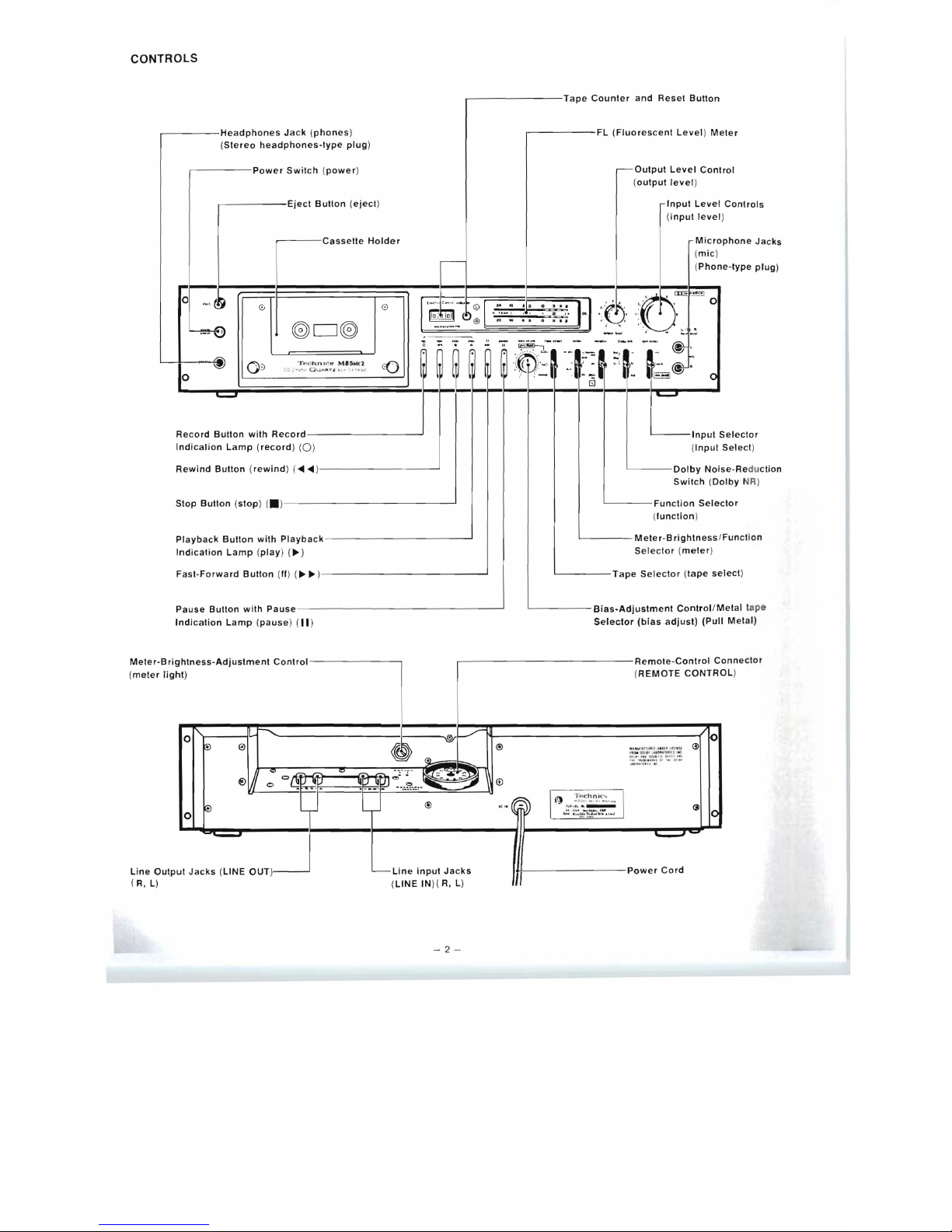
CONTROLS
~-----Fl
(Fluorescent
level) Meter
.---Output
level
Control
(
output
level
)
Input
level
Controls
(i
nput
level
)
Microphone
Jacks
(
mic
)
-
(
Phone-type
plug)
Record
Bullon
with
Record----
-
------'
L----Input
Selector
Indicalion
lamp
(record)
(0)
(lnpul
Select
)
Rewind
Button
(rewind
) (
<III
<111
)--
- -
---
-----'
L-
- - -
Dolby
Noise
-Re du
ction
Switch (Dolby NR)
Stop
Button (stop
) (. )-
--
- -
----------'
L---
-
Function
Selector
(
function
)
L-----M
eter-B
rightness IFunction
Indication
lamp (play
)
(~)
Playback
Bullon
with
Playback------------.J
.-
- -
--
---Tape
Counter
and
Reset
Button
..-----Headphones
Jack
(phones)
(Stereo
headphones-type
plug)
,-
----Power
Switch (power
)
.------Eject
Button (eject
)
.--
--
Casselle
Holder
0
.,"
~~
0
~
0 D
C®
~
0
:::>
(0
T"
('
hnl(~ ~
M'5t.A
1C
1
~
:i
.•
". .
OUAaT~ ""
" "
11"
c::»
o
Selector (meter
)
Fast-Forward
Button (II
)
(
~~
) _ _ _
__________
.J
L---
--
Tape
Selector (tape
select
)
Pause
Button
with
Pause---
- - -
------
- - -
---'
'-------Blas-Adlustment
Contro I Metal tap
e
Indication
lamp
(pause
) (
II
)
Selector
(bias
adjust)
(Pull
Metal)
ghtness-Adjustment
Control
ht
)
0"
:---....
~
e
'"
®0
0
o{1i
~
~~
-
-.
~
\@r
~
®
""
~
~?__U~I
~;:.~~"
,
_~~
~
®
Remote-Control
C
(
REMOTE
CONTR
.l
p
"f.Un tu..
tb
.,.. ~.
ut
...
SI
<J>
~::~!~~~I~
l l ~~:t
:
~
®
",,(@)
~~
G
Ill)
:r~~I.~ n.~c_~.
...
I
'-
:;W , ~~~
..
0
t ... . 1 •
••
~:7~~~,,·.
"
..
J
1
0
-
ut
Jacks (LINE
OUT
)
L--
Line
input
Jacks
LINE
IN
R
)(
l
, )
~-
I
Power
Cord
onnector
(
meter
lig
Meter-Bri
Ol
)
Line
Outp
(R,
l)
-2
-
Page 4

'
CONNECTION
Wireless
Remote
Control
,
Remote-Control
/
Unit
(RP-OlO,
optional) ' ""
Connector
.
~
LINE INPUT
Stereo
Connection
r-=~-=~~---
~~~--------
~
phones
mic
n
LINE
OUTPUT
Cords
'----
---y]
~
(RP-023P)
Headphones
(80)
Microphones
PLAYBACK
'"
(
RI
Stereo
Amplifier
I
ILl
REC OUT
Speaker
(L)
Speaker
(Rl
'---TU_NER-----j
fo:
1
i
~
\
3j
(e-
CD
c:::J
, '.' ; ' . ' : ' .. '
r·.
'. ','
, : I
_
)J
-
..
Turntable
Stereo
Tuner
Connection Note
Connections
should
be
made
in
accordance
with
the
connection
diagram
and
the
following
instructions.
When 2 microphones
are
used
in
order
to
record
in
:1
~~ n~'¥¥fB
~
n
-:
_. , -: ~"I· ,'
.:
r:",'.,
-,-,,"'.
Tape
Deck
I
stereophonic
sound,
be
sure
both
of
them
have
the
,
...
"
~
- - -,
-:
.
..-
.'
same
specification
standards
.
Location of this unit and
stereo
amplifier
If
this
unit
is
placed
on
top
of
the
st
ereo
amplifier
or
next
to
it, a
"hum" noise
may
be
heard
during
tape
playback.
Refer
to
the
information
below
in
order
to
avoid
this
.
(1) If
the
stereo
amplifier
and
this
unit
are
placed
one
above
the
other,
leave
as
much
space
as
possible
between
them,
and
place
them
where
there
is
the
least
amount
of
hum
.
(2)
If
the
ste
reo
amplifier
and
this unit
are
placed
one
be-
side
the
other,
try
reversing
their
positions,
and
place
them
where
there
is
the
least
amount
of
hum
.
.........
Stereo
Amplifier
Tape
Deck
Stereo
Amplifier
Tape
Deck
-::\
-
Page 5
I
I
I
I
II
I
I
I
I
I
I
I
I
I
I
I
ABOUT CASSETTE TAPE
The
cassette
tape
used
in
this
unit
is
the
universal
type
used
throughout
the
world.
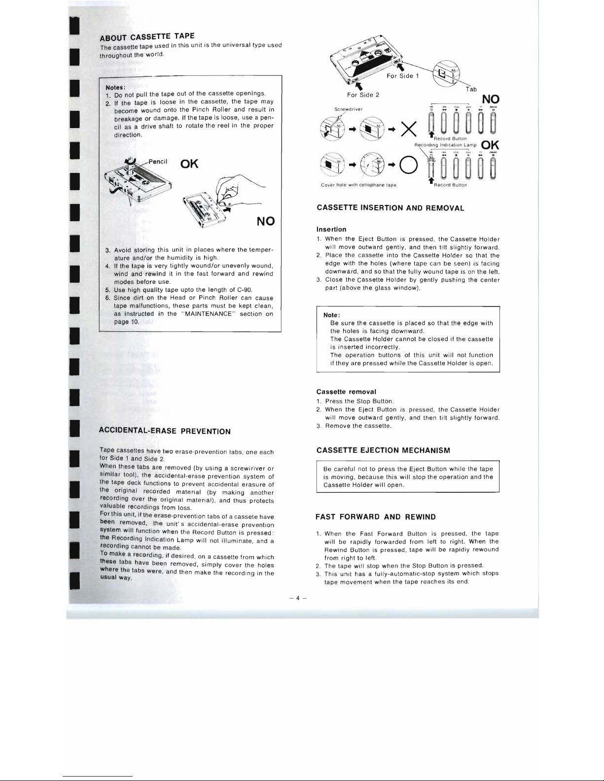
Notes
:
1.
Do
not
pull
the
tape
out
of
the
cassette
openings.
2.
If the
tape
is
loose
in
the
cassette,
the
tape
may
become
wound
onto
the
Pinch
Roller
and
result
in
breakage
or
damage
. If
the
tape
is
loose,
use a pen-
cil
as a
drive
shaft
to
rotate
the
reel
in
the
proper
direction
.
OK
NO
3.
Avoid
storing
this
unit
in
places
where
the
temper-
ature
and/or
the
humidity
is
high.
4.
If
the
tape
is
very
tightly
wound/or
unevenly
wound,
wind
and
rewind
it in
the
fast
forward
and
rewind
modes
before
use.
5. Use
high
quality
tape
upto
the
length
of C-90.
6.
Since
dirt
on
the
Head
or
Pinch
Roller
can
cause
tape
malfunctions,
these
parts
must
be
kept
clean,
as
instructed
in
the " MAINTENANCE"
section
on
page
10.
ACCIDENTAL-ERASE PREVENTION
Tape
cassettes
have
two
erase-prevention
tabs,
one
each
for
Side
1 and
Side
2.
When
these
tabs
are
removed
(by
using a screwiriver
or
similar
tool),
the
accidental-erase
prevention
system
of
the tape
deck
functions
to
prevent
accidental
erasure
of
the
original
recorded
material
(by
making
another
recording
over
the
original
material), and
thus
protects
valuable
recordings
from
loss
.
For
this
unit,
if
the
erase-prevention
tabs of a
cassete
have
been
removed,
the
unit's
accidental-erase
prevention
system
will
function
when
the
Record
Button
is
pressed:
the
Recording
Indication
Lamp
will
not
illuminate,
and a
recording
cannot
be
made.
~o
make a recording,
if
desired,
on a
cassette
from
which
hese
tabs have
been
removed, simply
cover
the
holes
where
the tabs
were,
and then
make
the
rec
ording
in
the
Usual
way
.
-4-
NO
..
x
Caver
hole
with cell
ophane
lap
e.
CASSETTE INSERTION AND REMOVAL
Insertion
1.
When
the
Eject
Button
is
pressed,
the
Cassette
Holder
will
move
outward
gently,
and
then
tilt
slightly
forward.
2.
Place
the
cassette
into
the
Cassette
Holder
so
that
the
edge
with
the
holes
(where
tape
can
be
seen)
is
facing
downward,
and
so
that
the
fully
wound
tape
is on
the
left.
3.
Close
the
Cassette
Holder
by
gently
pushing
the
center
part
(above
the
glass
window)
.
Note:
Be
sure
the
cassette
is
placed
so
that
the
edge
with
the
holes
is
facing
downward.
The
Cassette
Holder
cannot
be
closed
if
the
cassette
is
inserted
incorrectly
.
The
operation
buttons
of
this
unit
will
not
function
if
they
are
pressed
while
the
Cassette
Holder
is
open
.
Cassette
removal
1.
Press
the
Stop
Button
.
2. When
the
Eject
Button
is
pressed,
the
Cassette
Holder
will
move
outward
gently, and
then
tilt
slightly
forward
.
3.
Remove
the
cassette.
CASSETTE EJECTION MECHANISM
Be
careful
not
to
press
the
Eject
Button
while
the
tape
is
moving,
because
this
will
stop
the
operation
and
the
Cassette
Holder
will
open
.
FAST FORWARD AND REWIND
1.
When
the
Fast
Forward
Button
is
pressed,
the
tape
will
be
rapidly
forwarded
from
left
to right. When the
Rewind
Button
is
pressed, tape
will
be
rapidly
rewound
from
right
to
left.
2.
The
tape
will
stop
when
the
Stop
Button
is
pressed
.
3.
This
unit
has a fully-automatic-stop
system
which
stops
tape
movement
when
the
tape
reaches
its
end.
Page 6

METAL
TAPE
A
word
about
"Metal
tape"
Conventional cassette
tape
s can
be broadly
classified
into
2
categories according
to
the
magnetic
material
coated
on
the
tape surface : the
ferric-oxide
(r-Fe
20 3)
type
including
ordinary
LH
tape,
etc
.;
and
the chrome-dioxide
(Cr0
2)
type.
Continued
technologi
cal
advances
have
been
made
in
an
attempt
to
develop
these
tapes
to a high
level
of
perform
-
ance,
but
recently
there
has
been a recognized need
for
the
development
of a
new
material
to
improve
performance
much
further.
In
response
to
this
need,
"Metal
tape" has
been
developed
as a new
kind
of
tape, employing a magnetic alloy
of
pure
iron
(Fe)
as
the
main
component
in
the
magnetic
substance.
In
comparison
with
conventional
cassette
tape
, "
Metal
tape
"
can
record a far
greater
amount
of
information
at a
high
density. As a result,
the max
imum
output
level
(MOL)
has
been
improved
throughout
the
entire
range,
and
, in
partic
-
ular, the
frequency
response
characteristics
at
high
levels
and
the
dynamic
range
in
the
high
range
have
been
greatly
improved
.
This
means, therefore, that a remarkable
improvement
of
sound
quality
has
been
made
possible
.
(It
should
be
noted
that
the
tape
base
and
parts
of
the
tape
other
than
the
magnetic
substance
are
composed
of
the
same
material
as
previously used.)
Advantages
and
magnetic
characteristics
of
"Metal
tape"
1.
Maximum
output
level
(MOL)
is
greater
at
all
frequen-
cie
s.
2. Ex
cellent
frequency
response
characteristics
at
high
input
level.
3.
Wide
dynamic range
at
high
frequencies
.
4.
Excellent
signal-to-noise
ratio
at
high
frequencies
.
5.
Low
distortion
.
Residual
! o· _
magnelr
~
/ 1
-!
"Melallaoe"
"Metal
tape
"
magnetic
characteristics
Coe
rcive
f()fce
"Metal
tape "
frequency
response
example
0 118 1
60n
W b
rn
_
!.C.......
...... _ ftWL-
. _ _ ,
__
4-
...
..
......
rm
l!:t
i~rJJm
··-i
J4
#.'"f
fj±!f
~I
'
E:EEEii
~ ~Met;t IB~
;-
T
cr + "11
, 0
..JIDIl-*R
I
The"
Metal
tape" selector
"
Metal
tapes" significantly
improve
the
performance
of
the
tape deck, but,
becau
se
there
is a
difference
of
bias
char-
acteristics
and
the
erase
characteristics
between
conven-
I
tional
and
"Metal
tapes
" , it
is
now nec
essary
to
have a spe-
cial
tape
selector
position
for " Melal
tape".
Our
tape
recor-
ders will
bear
the"
Metal" designation
for
this
position
of
the
tape selector.
I
I
The
"Metal"
position
using
I
1.
Playback
time-constant
...
70J.lS
(same
as
at
the " Cr0
2"
position)
2.
Bias
current
.about
150%
Higher
(compard
to
"
CrOz" position)
3.
Erase
current
.. .
about
150%
Higher
(compared
to
"CrO
z"
position)
4.
Recording
equalization ...
Special
equalization
I
Technological
developments
to
accomodate
"Metal
tape"
I
"Metal
tape"
is a
totally
new
kind
01
high
performance
tape,
and
conventional
cassette
tape
decks
cannot
suffi-
ciently
bring
out
its
performance
potential.
Our
company has
succeeded
in
developing
the
following
I
technology
to
exploit
the
advantages
of
"Metal
tape
" to
its
fullest
extent.
1.
Development
01
SX
Head
with
minimal
distortion
accom-
panying
high
input
signal
levels
The
SX (s
endust)
Head has a
high
level
of
saturation
mag-
netic
flux
density
and
it
is i
deal
for
"Metal
tape" which
feature a high
MOL
(maximum
output
level)
.
We
have
further
improved
the
conventional
SX
Head
.
I
2.
High
efficiency
Erase
Head
Conventional
Erase
Head
does not
adequately
erase
"
Metal
tapes."
I
Our
company
has
developed a new
Erase
Head
with
a
S
endust
tip
.
I
3.
Increased
power
in
the
bias
oscillation
circuitry
"
Metal
tape" require
s an
erase
current
and a bias current
I
that
are
both
1.5
times
greater
than
those
of
chrome-
dioxide
tape
.
We
have
increased
the
power
in
order
to
provide
this
current
and
maintain a low
distortion
ratio.
I
I
-5-
Page 7

TAPE SELECTOR
HOW TO USE THE BIAS-ADJUSTMENT
I
I
I
I
I
I
I
I
I
I
I
I
I
In
order
to
get
the
best
performance
from
tape , and
to
record
CONTROL
and
playback
with
little
distortion, the
Tape
Selector
should
This
unit
includes a system
for
minor
adjustments
of
the
be
set
as
shown
below.
recording
bias. The
system
is
designed
so
that
optimum
Tape
Selector
Setting
Brand
Tape
Type
AMPEX
GRAND
MASTER
I
C-60, C-90
BASF
PROFESSIONAL
I
C-60, C-90
FUJI
FX
I
C-60, C-90
normal
MAXElL
UD
C-60, C-90
MAX
ELL
UDXL I
C-60, C-90
SONY
UHF
C-60, C-90
TDK
AD
C-60, C-90
Fe-Cr
BASF
PROFESSIONAL
ill
SONY
Fe-Cr
SCOTCH
MASTERm
C-60
C-60
C-60
AMPEX
GRAND
MASTER
IT
C-60
BASF
PROFESSIONAL
IT C-60
Cr0
2
FUJI
FX
IT
MAXELL
UDXLll
C-60
C-60
SCOTCH
MASTER
II
C-60
TDK
SA C-46, C-60
Metal
peformance
can
be
obtained
when
the
Bias-Adjustment
Control
is
set
to its
center
"click-stop" position,
and,
there-
fore,
it
should
be
set
to
this
position
for
best
recording
results
under
ordinary
conditions.
A
great
many
types
of
"low-noise,
high-output" tapes
have
appeared
recently,
however,
and
the
optimum
bias
value
which
will
result
in
the
flattest
frequency
response
charac-
teristic
is, to be
most
precise,
slightly
different
for
each
of
them
.
As a
result,
in
order
to
obtain
the
finest
possible
perform-
ance
from
each
of
these
types
of "
low-noise, high-output
"
tapes
, a
flatter
frequency
response
characteristic
can
be
obtained
by
making
minor
adjustment
of
the
bias
while
referring
to
figure
below.
Although
the
Bias-Adjustment
Control
will
function
when
the
Tape
Selector
is
set
to
either
the
"Cr02"
position
the
"Fe-Cr"
position
or
"Metal"
position,
it
is
suggested
that
this
control
be
set
to
the
center
"click-stop"
position
when
Cr0 2 or
Fe-
Cr
tape
is
used,
because
there
are
not a great
many
types
of
these
tapes,
and
there
is
not
much
difference
in
the
optimum
bias
setting
for
each
type
.
For
brands
of
tape
other
than
those
shown
in
figure
below,
the
optimum
bias
value
can
be
determined
by
recording
(at a recording
level
of
about
-20
dB)
the
characteristic
noise
heard
between
FM
broadcast
stations. When
this
recorded
noise
is
played
back.
It
should
have
the
same
noise
as
the
original
noise
heard
from
the
tuner.
If
not, readjust
the
Bias
and
repeat
the
test
procedure, until
the
recorded
noise
is
the
same
as
the
original
noise
heard
from
the
tuner.
This
setting
of
the
Bias-Adjustment
Control,
Note
that
there
may
be a difference
in
sensitivity
of 2 or 3 dB,
then,
is
the
best
position
for
use
with
such
tape
.
depending
on
the
type
of
tape.
AMPEX
GRAND
MASTER
I
~
"Metal
Tape"
SETTING
When
using " Metal
tape"
pull
the
Bias
Adjust
Controll
"Metal
tape" Selector
forward
to
its
click-stop
position,
also
TDK
AD
the
Tape
Selector
must
be
set
to
the
"Cr0
2"
position
.
((a·'.
~.
".
2
BASF
PROFESSIONAL
I
MAX
ELL UD
MAX
ELL
UDXLl
'----
P_H_IL_I_PS_~\.--/
'
FUJI FX I
r I
t'l
J.r
SONY UHF
*
The
examples
in
figu
re
above
are
based
upon
the
Tape
Selector
set
to
the
"normal"
position.
*There
may
be a
slight
difference
even
for
tapes
of
the
same
brand.
*
The
BiaS-Adjustment
Control
has
no
elfect
during
playback.
*
The
Bias
cannot
be
finely
adjusted
will " Metal
tape".
FREQUENCY
RESPONSE
VS.
BIAS
LEVEL
I
~
".~
.....
,"",.'
so
..
__
AMS
'
,-:, ,~_
.
20
" I
~
:..:,
' "
,, ~-
" """
.'
-
=:'
•••
I
-6-
Page 8

I
PLAYBACK
Note:
•
Note
that
the
operation
buttons
will
not
function
alter
the
power
is
turned
on
until
approximately 5 second
s
have
passed.
This
muting
circuitry
is
used
in
order
to
eliminate
annoying
click
noise.
1.
Press
the
Power
Switch
to
the
"on"
position
.
2.
Alter
pressing
the
Eject
Button,
place
the
cassette
in
the
cassette
hofder,
and
then
close
it.
3.
For
ordinary
tape
playba
ck,
set
the
Dolby
Noise-
Reduction
Swi
tch
to
the
"out" position.
For
playback
of
a
tape
recorded
by
the
Dolby
system. set
the
switch
to
the
"in" position
.
4. Set
the
Tape
Selector
to
the " normal."
"Cr0
2
" "
Fe-Cr"
or " Metal"
position, depending
upon
the
type
of
tape
to
be
used.
(Refer
to
the
section " Tape
Selector"
on
page
6.)
5.
Press
the
Reset
Button
to
reset
the
numbers
to
"
000"
.
6.
When
the
Play
Button
is
pressed,
the
Playback
Indication
Lamp
will
illuminate
and
playback
will
begin.
7. Set
the
Output-Level
Control
to
its
maximum
position
.
•
This
unit
is
designed
so
that
the
rated
output
of
the
Line-Output
Terminals
("LINE
OUT " )
is
700
mV
when
the
Output-Level
Control
is
set
to
its
maximu
m
position
("10")
and
the
" 0
dB"
indication
of
the
Fluo-
rescent
Level
Meter
is
illuminated.
8.
Adjust
the
volume
level
and
tone
quality
by
using
the
volume
control
and
tone
controls
of
the
stereo
amplifier
to
which
this
unit
is
connected.
•
When
listening
through
headphones,
adjust
the
volume
level
by
using
the
Output-Level
Control
of
this
unit.
9.
Press
the
Stop
Button
to
stop
tape
playback. Note
that
the
tape
movement
will
be
automatically
stopped
by
the
Automatic-Stop
system
when
the
tape
reaches
its
end
.
•
When a record
player,
tuner
or
other
equipment
is
connected
to
the
stereo
amplifier
to
which
this
unit
is
connected,
it
is
suggested
(for
convenience
when
using
the
input
selector
of
the
setereo
amplifier)
that
the
output
level
of
this
unit
and
of
other
con-
nected
equipment
be
set
to
the
same
level.
-7-
RECORDING
1.
Press the Power
Switch
to
the
"on " position
.
2. A
fter
pressing
the
Eject
Button, place
the
cassette
in
the
I
Cassette
Holder, and
then
close
it.
3.
If
the
recording
is
to
be
made
by
using
the
Dolby
Noise-
Redu
cti
on
system. set
the
Dolby
Noise-Reduction
Switch
to
the " in"
position.
For
an
ordinary
recording , set
it
I
to
the
"out" position
.
4.
Set
the
Tape
Selector
to
the
"normal,"
"Cr0
2
" ,
"Fe-
Cr"
or " Metal" position, depending
upon
the
type
of
tape
to
be
used.
I
(Refer
to
the
section
"Tape
Selector" on
page
6.)
5. If
minor
adjustment
of
the
bias
is
necessary,
use
the
Bias-Adjustment
Control.
(Refer
to
the
section " HOW
TO
USE THE
BIAS-ADJUST-
I
MENT
CONTROL"
on
Page
6.)
6.
If
the
recording
is
to
be
made
from a sound
source
connected
to
the
Line
Input
Jacks,
set
the
Input
Selector
to
the
"line
in"
position;
and,
if
the
recording
is
to
be
made
through
microphones, set
it
to
the
"mic" position
.
7.
When
the
Record
Button
is
pressed,
the
Recording
Indication
Lamp
will
illuminate, and
the
unit
will
be
in
the
recording
stand-by
condition.
The
recording
level
can
be
adjusted
at
this
time.
When
adjusting
the
recording
level,
use
the
Input
Level
Controls
to
adjust
50
that
the
"0
dB"
indication
is
not
exceeded
even
when
the
signal
is
at a
high
level
.
I
(Refer
to
the
section " Adjustment
of
the
recording
level."
on
page
8,
for
further
details.)
8.
Press
the
Reset
Button
to
reset
the
numbers
to
"000
."
I
9.
When
the
Playback
Button
is
pressed , the
Playback
Indication
Lamp
will
illuminate,
and
the
recording
will
begin
.
10.
To
temporarily
stop
tape
movement
while
recording.
I
press
the
Pause
Button. The
tape
movement
will
then
stop, and
the
Pause
Indication
Lamp
will
illuminate,
but
the
unit
will
remain
in
the
recording
mode.
To
resume
recording,
press
the
Playback
Button
to
start
tape
movement.
11 . Pres5
the
Stop
Button
to
stop
the
recording. Note
that
the
tape
movement
will
be
automatically
stopped
by
the
Automatic-Stop
system
when
the
tape
reaches
its
end.
Notes:
1.
After
making a valuable
recording,
it is
suggested
that
the
accidental-erase
prevention
tabs
be
re-
moved,
using a screwdriver
or
similar
tool , in
order
to
prevent
accidental
erasing
of
the
recording
by
I
later
re-recording
over
it.
2 .
For
recording, therefore,
be
sure
that
the
cassette
has
the
tabs
intact, or
that
the
holes
(where
the
tabs
were)
are
covered
by
cellophane
tape.
I
3.
Note
that
no
sound
will
be
recorded
on
the
tape
if
the
Input
Selector
is in
the " rec
mute"
position
.
even
though
monitor
sound
can
be
heard
and
the
Fluorescent
Level
Meter
continues
to
function.
I
4.
For
recording, the
Record
Button
must
be
pressed
fir
st,
then
the
Playback
Button
.
*
For
information
concerning
record
muting,
refer
to
page
10.
I
I
Page 9

FLUORESCENT LEVEL METER
The
FL
Level
Meter
of
this
unit
is a new
type
meter,
and
is
completely
different
in
principle
than
conventional
level
meters
which
have
indication
needles.
It
can,
however,
be
used
the
same
way
for
adjustment
of
the
recording
level.
During
playback
it
indicates
the
playback
level,
and
during
recording
it
indicates
the
recording
level.
In
addition,
because
the
meter
of
this
unit
can
be
used
for
both
peak
and
VU
indication,
it
is
possible
to
make
record-
ings
with a good
signal-to-noise
ratio,
with
little
distortion,
and
with
the
tape
recorded
to
its
very
limit
of
saturation
.
When
the
Meter-Brightness/Function
Selector
is
set
to
the
I
"PEAK"
position,
the
word
"PEAK"
will
illuminate
on
the
surface
of
the
meter
.
The
FL
Level
Meter
scales
are desi
gned
to
indicate
in
2
colors
to
make
instant
recognition
easy:
yellow
below
"0
I
dB
" ,
and
orange
above
" 0
dB."
I
1.
Adjustment
of
the
recording
level
"VU"
position:
Adjust
so
that
the
illumination
of
the
meter
does
not
exceed
the
"0
dB"
indication
at
the
greatest
signal
level.
I
VU
position
11111111111111111111111111111111111111111111111111+1
3 5
8
(L)
CD
(R)
3 5 B
111111111111111111111111111111111111111111111111111+1
I
"
PEAK"
position:
Adjust
so
that
the
illumination
is
up
to
the
"+5
dB"
p
os
ition.
I
In
the
same way
as
for
the
"VU"
indication,
adju
st
so
that
the
il
luminat
ion
does
not exceed
the
" 0
dB
"
indicati
on.
Then
set
the
Meter-Brightness/Function
Selector
to
the "PEAK"
position, and,
if
the
illumination
moves
as
hi
gh
as
the " +8
dB"
position, use
the
Input
I
Level
Controls
to
reduce
the
level
so
that
the
meter
illu
min
ate
up
to
the "+5 dB" p
osition when
the
Meter-
Brightne
ss/Func
tion
Selector
is
set
to
the "PEAK
"
position.
PEAK
position
11111111111111111111111111111111111111111111111111111111111111111111111+1
I
(L)
E
1
-
1+
(R)
-
1
111111111111111111111111111111111111111111111111111111111111111111111~
I
I
I
I
2.
Difference
in
illumination
at
the
"PEAK"
and
"VU"
positions
:
Unlike
ordinary
level
meters,
the
EL
Level
Meter
of
this
unit
has a fast
indication
response,
responding
with
perfect correspondence
to
input
signals
. It
can,
therefore
be
used
for
very
precise
indication
of
peak
signals.
s
ignals
.
The
illuminated
indications
differ,
as
shown
below,
depending
upon
whether
the
setting
is
to
the " PEAK
"
position
or
to
the " VU"
position
.
VU
position
111111111+1
u
(L)
-+-
(R)
I"''''''~
e 3
r)
:3
al
3
S
IS
e
'
..
"
PEAK
position
111111111111111111111111+1
Momentary
sound
(L)
(R)
".
I
0
0
!XI
3
15
&
+
B
111111111111111111111111+1
(R)
(L)
~
Continuous
sound
(L)
(R)
VU
position
1111111111111111111111111111111111+1
:)
5 8
!XI
1
'3
15
11111111111111111111111111111111111+1
PEAK
position
1IIIIIIIIIIIIIIItlltllllllllllllllllll+l
:3
5
/1
F',
III
...
,
3 0
3
~
1
1111111111111111111111111111111111111+1
3.
Selection
of
brightness
of
FL
Level
Meter:
The
Meter-Brightness /Function
Selector
can
be
used
to
select
either
of two
degrees
of
brightnes
s o f the
FL
Level
Mete
r.
When
it
is
set
to
the
"dim"
position,
the
brightness
is
less
than
at
the
"bright" position,
and, when
it
is
set
to
the
"bright"
position,
the
Meter-Brightness-Adjustment
Control
on
the rear
panel
can
be
used
for
further
adjust-
ment
to
any
desired
degr
ee ·
of
bright
ness
between
the
"dim " and " bright"
illumination
.
MONITORING
To
listen
to
the
recording
as
it
is
being
made,
sim
ply
con-
nect stereo
headph
ones
(80)
to
the
Headph
ones
Jack
,
You
may
also
listen
to
the
program
as
it
is
being
recorded
if
your
rece
iver
or
amplifier
is
equipped
with a tape-moni-
tor
switch.
-8-
Page 10

TIMER RECORDING AND
PLAYBACK
This
unit
is
designed
so
that
timer
recordings and
playback
are possib
le simply
by
setting
the Function
Selector.
Re
cord
ing
or
playback
will
automatically
begin,
if
the
Function
Selector
is
set
to
the
"timer
rec"
posi
tion,
when
the
power
is
turned
on
by
the
timer.
If
the
rec
ord
ing-prevention
tabs
of
the
cassette
are
inta
cl,
a
timer
recording
will
then
be
made.
If
th
ey
are
not
intact.
timer
playback
will
begin
automatically.
When
not
using
the
unit
for a timer
recording
or
timer
playback,
therefore
,
be
sure
to
set
the
Function Selector
to
the
"of
I"
position
.
Recording
with a Timer
(Timer
recording
of
FM
broadcasts)
1.
Make
connections
to
the
power
source
as shown
in
the
figure
below.
2.
Insert a tape
upon
which
no
recording
has
been
made
or
one
which
has
been
erased,
and
which
has
its
accidental-
erase-prevention
tabs
intact
(or
has
the tab
holes
convered
by
cellophane
tape
),
and
turn
on
the
power.
If
a
new
recording
is
to
be
made
of
an
already-rec-
orded
tape,
erase
the
fir
st
part
of
the
recording
be-
forehand
(in
order
to
assure
that
none
of
the
previ-
ous
sound
appears
it
the
new
recording).
and
then
prepare
the
tape
so
that
the
new
recording
will
begin
from a part
of
the
tape
that
has
been
completely
erased
.
3.
Turn
to
the
FM
broadcast
station , press
only the
Record
Button,
and
then
adjust
the
recording
level.
4.
Set
the
timer
to
the
time
the
recording
should
begin.
(
Depending
upon
the
type
of
timer,
the
power
might
be
turned
off
at
this
time.)
5.
Set
the
Function
Selector
to
the '·timer
rec " position
.
This
completes
the
preparations
for
making a timer
recording.
When
the
power
is
turned
on
(by
the
timer).
the
FM
broadcast
will
be reco
rded
automatically
.
Power
Source
Stereo
Cassette
Deck
RS-M85MK'
1.
co
c:::::J
I
,~. ~
.
'"
0.'"
" .'.;-"-.';,.,;.
I
Stereo
Tuner
\-
~
> - - - -
AC
OUTL~
j
s:.:.:,::,:".,
..
! ~~~:f~R
~~-
1
..
'
AC
soc
ket
Timer
Timer
playback
1. In s
ert a recorded
cassette
from
which
the
record-
prevention
tabs have
been
removed,
and
make
con-
nections
in
the
same
way
as
for
Timer reco
rd .
2.
Set
the
Output-level
control
to
its
max
im
um
position
.
3.
Playback
the
tape
in
order
to
make
adjustments
(at
the
stereo
amplifier)
to
the volume
level
and
tone
quality
desired
when
the
timer
playback
begins.
4.
Rewind
the
tape
to
the
position
where
timer
playback
is
to
begin,
and
set
the
timer
to
the
desired
time.
(Depending
upon
the
type
of
timer,
the
power
might
be
turned
off
at
this
time.)
5.
Set
the
Function
Selector
to
the
"timer
rec'"
position
This
completes
the
preparations
for
timer
playback.
AI
the
desired
time,
the
power
will
be
turned
on
and
the
timer
playback
will
begin.
Notes:
•
When
preparing
for
timer
playback,
first
play
the
tape
in
order
to
adjust
(by
using
the
controls
on
the
stereo
amplifier)
the volume
and
tone
as
desired.
When
these
adjustments
are
finished,
rewind
the
tape
to
the
position
from
Which
the
timer
playback
is
to
begin
.
•
Before
using
the
timer,
refer
to
its
operating
instruc-
tions.
•
For
timer
recording
and
playback,
the
muting
circuitry
will
operate
when
the
power
is
turned
on,
delaying
the
start
of
operation
for
about 5 seconds.
----------------~
MEMORY
REWIND
The " Memory Rew
ind"
system
can
be
used
to
conveniently
return
the
tape
automatically. during
rewind
, toany
desired
position
.
Convenient
uses
of
the
Memory
Rewind
system
1.
To
return
to
the
beginning
of a recording
and
play
it
back
immediately
after
making
the
recording
.
2.
To
repeatedly
begin
playback
many
times
from
the
same
position.
How
to
use
the
Memory
Rewind
system
1.
When,
during
recording
or
playback,
the
tape
reaches
the poi
nt
to
which
it
should
later
be
returned,
push
the
Reset
Button
to
reset
it
to
"
000."
2.
At
the
same
time,
set
the
Function
Selector
to
the
"memory
rew"
position.
3.
When
the
recording
or
playback
is
finished,
stop
the
tape mov
ement
by
pressing
the
Stop
Button,
4.
Then,
by
simply
pressing
the
Rewind
Button,
the
tape
will
be
rewound
to a position
slightly
prior
to
the
"000"
reading
of
the
Tape
Counter,
where
the
tape
will
auto-
matically
stop.
5.
After
the
tape
has
been
rewound
and
stopped
at
the
pre-set
position
in
this
way,
tape
rewind
can
be
continued,
if
desired,
by
pressing
the
Rewind
Button
once
again.
-9-
I
I
I
I
I
I
I
I
I
I
I
I
I
I
Page 11

I
RECORDING MUTING
I
The
record-muting
feature
is
convenient
to
prevent
record-
ing
such
unwanted
material
as
commercial
messages
when
recording
FM
radio
broadcasts,
or
the "click"
noise
heard
when
the
slylus
descend
s to
the
disc
surface
.
I
Becau
se
Ihis
unit
is
designed
so
that
switching
can
be
made
by
using
the
Input
Seleclor
, u
se
this
feature
when
recording
from a source
connected
10
the
Line
Input
Jacks.
Use
of
the
record-muting
function
I
When
the
Input
Selector
is
set
to
the
"rec
mute"
position,
I
the
sound
source
can
still
be
heard
and
the
Fluorescent
Level
Meter
will
not
continue
to
show
indications,
and
no
sound
will
be
recorded
on
the
tape
.
1. When
recording
an
FM
radio
broadcast
To
avoid
recording
unwanled
material
such
as
com-
mercial messages
listen
to
the
monitor
sound
and,
when
a
tune
reaches
its
end,
set
Ihe
Input
Selector
to
the
"
rec
mute"
position.
Next,
push
the
Pause
Button
after
lelting
the
tape
continue
to
move
for
about 5 seco
nds,
and
then
return
the
Input
Selector
to
the " line
in"
position. Then,
while
listening
to
the
monitor
sound,
once
again
press
the
Playback
Bulton
just
before
the
next
tune
begins.
2.
When
recording
from a phono
disc
To
avoid recordi
ng
the
"click"
noise
which
occurs
when
the
stylus
descends
to
the
record
surface,
first
press
the
Record
Bulton
and
the
Pause
Bulton,
and
then
begin
the
disc
play
and
adjust
the
recording
level.
Next, lift
the
styl
us up
from
the
disc,
and set
the
Input
Selector
to
the
" rec
mute"
position.
Then
press
the
I
Playback
Button
to
begin
the
tape
moving
in
the
recording
mode. and.
after
lowering
the
stylus
to
the
I
disc
surface,
set
the
Input
Selector
to
the
"line
In
position.
By
following
th
ese
steps. the
"click"
noise
will
not
be
recorded
.
3.
Other
uses
The
tape
can
be
erased
by
setting
the
Input
Selector
I
to
the " rec
mute"
position
and
moving
the
tape
in
the
recording
mode.
without
setting
the
Input
Level
Controls
to
the
minimum
position
.
I
Note:
Before
beginning a recording,
always
first
check
to
I
be
sure
that
the
Input
Selector
is
not
set
to
the " rec
mute"
position.
If it
remains
in
that
position,
monitor
sound
will
still
be
heard
and
the
FL
Level
Meter
will
not
function,
and
no
sound
will
be
recorded
on
the
tape.
I
AUTOMATIC-STOP SYSTEM (
Full-Auto-Stop
I
System)
Th
is
unit
has a full
automatic-stop
system.
When
the
tape
comes
to
its
end
during
recording,
playback,
fast
forward
or
rewind,
the
tape-transport
mechanism
automatically
releases
and
places
the
unit
into
the
stop
mode
.
I
*
Because
the
mechani
sm
automatically
stops
when
the
tape
comes
to its
end, both
the
operating
parts
and
the
tape
itself
are
protected.
This
unit
is
free
from
problems
I
such
as Pinc h Ro
ller
deformation
resulting
from
leaving
the
unit
in
the
stop
condition
(without
pushing
the
Stop
Button)
for
a lo
ng
period
of
time
.
-10-
DOLBY RECORDING
This
unit
includes
the
Dolby
noise-reduction
system,
which
red
uces
tape
noise
to a rema
rkable
deg
ree.
Briefly,
the
system
works
as
follows : At
low
sound
levels
(whe
re
tape
noise
is
most
noticeable), the
high-frequency
portion
of the sound
is
recorded
at a
higher
level. Tape
noise
is no t
amplified
.
During
playback,
the
level
of on
ly
that
portion
of
the
signal
which
was
increased
at
the
time
of
the
rec o
rding
, as
well
as
tape
noise,
is
reduced
by a like
amount.
Thi s causes
the
signal
to
be
heard
at a
normal
level, and
the
tape
noise
to
be
reduced
significantly.
MULTIPLEX FILTER
FM
stereo
broadca
st
signals
consist
of a 19
kHz
pilot
signal
and
a 38
kHz
sub-carrier. When a Dolby
recording
is
made
of
an
FM
stereo
broadcast,
the
Dolby
circuitry
will
not
function
correctly
because
it
detects
signals
leaking
from
the
FM
tuner.
For
this
reas
on,
the
broadcast
signals
pass
through a multiplex
filter
system
to
remove
the
unwanted
signals,
thus
assuring
that
Dolby
recordings can
be
correctly
made.
Except
when
recording
FM
stereo broadcast.
set
the
Dolby
Noise-Reduction
Switch
to
the "filter
out"
position
.
REMOTE-CONTROL
OPERATION
Because this
unit
employs
an
electronically-controlled
system
for
operation, using
IC
logic
circuitry,
the
operations
of
the
unit
can
be
controlled
from a distance
by
using
the
RP-070
Wireless
Remote-Control
Unit
or
the
RP-9690
Re-
mote-Control
Unit
(both
available
optionally
as a separate
purchase)
,
ERASING
When a new
recording
is
made, any
previously
recorded
material
on
the
tape
is
automatically
erased,
and
only
th e
new
recording
remain
s.
To
completely
era
se a recorded
tape,
set
the
Input
Selector
to
the
"rec
mute"
position
or
set
the
Input
Level
Controls
to
their
minimum
("0")
position.
Then
set
the
Tape
Selector
to
the
"CrO,'
position,
set
the
Bias-Adjustment
Control
to
its
center "click"
position,
and
then
operate
the
unit
in
the
recording
mode.
To
erase
"Metal
tape",
set
the
"Metal
tape"
Selector
to
the
"Metal"
position
and
then
allow
the
tape
to
run
as
instructed
under
the
procedure
for
recording.
By
following
this
procedure
in
both
directions, all
recorded
material
on
the
tape
can
be
erased.
Page 12

I
RACK MOUNTING
MAINTENANCE
Because
the
Head
Assembly,
Pinch
Roller
and
the
Capstan
This
unit
is
constructed
to fit
racks
of
E,I,A,
Standard
are
in
constant
contact
with
the
moving
tape, dirt
or
residue
specifications
(19
inch
racks)
,
from
the
tape
on
these
parts
will
decrease
the
sound
quality.
I
For
rack
mounting, attach
to
the
rack
by
using
bolts
and
They
should
be
cleaned
after
every
10
hours
of
use,
as
nuts
(or
screws,
if
the
rack
holes
are
threaded)
which
fit
described
below:
the
rack
holes,
I
1,
Press
the
Eject
Button
to
open
the
Cassette
Holder.
2,
To
make
cleaning
of
the
Head
Assembly
easier,
loosen
the
screws
holding
the
glass
window
of
the
Cassette
Holder
and
remove
the
glass,
Hold
the
glass
with
one
I
hand, (when
loosening
the
screws)
so
that
you
do
not
accidently
drop
the
glass
door,
I
I
I
I
3,
Clean
the
surfaces
of
the
Heads,
the
Capstan,
the
Pinch
Roller,
etc. by
using a cotton
swab
or
other
soft
cloth,
If
these
parts
are extremely
dirty,
dip
the
cotton
swab
or
cloth
in a
little
alcohol
in
order
to
make
cleaning
easier
,
I
Tape
Guide
Erase
Head
Pinch
Roller
I
Record /Playback
Head
I
Notes:
1,
Don't
allow
magnetic
materials,
such
as a
Screw-
driver
or a magnet,
near
the
Head
Assembly
.
2.
When
cleaning,
be
careful
not
to
bend
the
Tape
I
Guides.
3, Don 't
attempt
to
clean
the
cabinet
with
alcohol,
benzine
or
thinner,
because
it
will
damage
the
finish,
If
the
cabinet
is
dirty,
clean
with a soft
cloth
I
dampened
with a soap-and-water
solution
.
4,
Handle
the
glass
window
(removed
to
facilitate
clean-
ing
of
the
heads)
with
care,
because
it
might
break
if
dropped,
I
5,
When
"Metal
tape"
is
used,
the
Head
Assembly
should
be
cleaned
after
each
10
times
of use .
I
-11
-
0)
Page 13

II
I
I
I
I
I
I
I
I
I
I
I
I
I
I
I
I
IN
CASE OF DIFFICUL TV
If
operation
of
this
unit
does
not
seem
normal,
check
the
following points
before
requesting
service
. If
the
trouble
cannot
in this
way
be
determined
and
corrected,
contact
the
dealer
from
whom
the
unit
was
purchased.
1.
After
the
tape
cassette
is
inserted,
the
tape
does
not
move
when
the
Play
Button
is
pushed.
• Is
the
Power
Cord
correctly
connected?
• Is the
Power
Switch
pushed
it
to
the
"on"
position?
2.
Although
the
tape
moves,
no
sound
is
heard.
•
Is
the
tape
blank?
•
Are
the
connections
of
amplifier
and
speakers
correct?
•
Are
connection
cords
from
this
unit
to
correctly
connected
?
•
Is
the vo
lume
control
01
the
connected
to the
correct
position?
• Is the
monitor
switch
of
the
connected
to the
correct
position?
3.
Sound
is
distorted.
• Is the
recording
level
too
high?
•
Is
the
pla
yba ck
output level too
high?
the
amplifier
a
mplifier
set
amplifier
sel
•
Is
the
input
impedance
01
the
connected
amplifier
ap-
propriate?
4. The
Record-Indication
Lamp
does
not
illuminate
when
the
Record
Bulton
is
pressed.
•
Is
the t
ape
cassette
inserted
correctly?
•
Have
the
recording
-p
revention
tabs of
the
cassette
been
removed?
5.
Tape
moves,
bul
no
sound
can
be
recorded.
•
Is
the
Input
Selector
set, in
error
, to the
"rec
mute
"
position?
•
Is
the
Input
Selector
set
to
the
incorrect
position?
6.
Playback
sound
is
hoarse
or
vibrates.
Recorded
sound
is
not
clear.
•
Are
the
head
surfaces
dirty
?
• Is
foreign
material
adhered
to
the
Pinch
Roller
andl
or
the
Capstan?
Accessories
Stereo
Connection
Cords
2
Product
Service
Should your
Technics
product
require
service,
refer
to
the
Directory
of
Authorized
Servicenters,
or
to
your
franchised
Panasonic
dealer,
for
assistance.
Do
not
send
the
product
to
the
executive,
or
regional
sales
offices.
They
are
not
equipped
to
make
repairs.
If
the
unit
is
brought
into a warm
room
after
it
has
been
in a
very
cold
location
(freezing
temperature), it
may
not
operate
properly
when
first
connected.
This
is
due
to
condensation
on
internal
parts
of
the
unit.
This
effect
will
disappear, if it
allowed
to
stand
for
30
minutes
or
so
in a
warm
room
before
being
used
.
1
'1
SPECIFICATIONS
Track
System:
Tape
Speed:
Wow
and
Flutter:
Frequency
Response
:
Si
gan
I-to-Noise
Ratio:
Fast
Forward
and
Rewind
Time:
Inputs:
Outputs:
Bias
Frequency:
Motors:
Heads:
Power
Requirements:
Power
Consump-
tion:
Dimensions
(HXWXD):
Weight:
4-track
2-channel
stereo
recording
and
playback
4.8
cm/s(1-7/8
ips)
0.
035%
(WRMS)
Metal
tape;
20-20,000
Hz
30-17,000
Hz
±3dB
CrO
2/Fe-Cr
tape;
20-18,000
Hz
30-16,000
Hz
±3dB
Normal
tape;
20-16,000
Hz
30-14,000
Hz
±3dB
Dolby
NR
in;
69
dB
(above
5 kHz)
Dolby
NR
out;
59
dB
(signal
level
=max.
recording
level,
Fe-Cr/CrO 2 type
tape)
Approx.
80
seconds
with
C-60
cassette
tape
MIC ; sensitivity 0.25
mV,
applicable
microphone
impedance
400
0-
10
kO
LINE;
sensitivity
60 mV,
input
impedance
68
kO
LINE;
output
level
700 mV,
load
impedance
22
kO
over
HEADPHONE;
output
level
140 mV,
load
impedance
80
85
kHz
2-motor
system
Capstan;
1-quartz
control
phase-
locked
DC
brush
less
direct-drive
motor
Reel
table
; 1-DC
core
less
motor
2-head
system
l-SX
(Sendust
Extra)
head
for
recl
playback
l-sendustlferrite
double-gap
head
for
erasure
AC;
120
V,
50-60 Hz
40
W
9.7
cm
x48.3
cm
X40.3
cm
3-7/8"
x
19"
x 15-718"
10.5 kg (23
Ibs 1 oz)
Specifications
are
subject
to
change
without
notice.
*
Noise
reduction system
manufactured
under lice
nse
from
Dolby
Laboratories.
Page 14

I
CAUTION
I
This
equipment
generates and uses radio frequency
energy and
if
not
installed
and used properly, that is, in
strict
accordance
with
the
manufacturer's
instructions,
may cause
interference
to
radio and television reception . It has been
I
type tested and found to
comply
with
the
limits
for
a Class B
computing
device in
accordance
with
the
specifications
in
Subpart
J
of
Part 15
of
FCC Rules, which are designed
to
pro-
vide reasonable
protection
against
such
interference
in a
I
residential
installation.
However, there is no
guarantee
that
interference will
not
occur
in a
particular
installation
. If
this
I
equipment does cause
interference
to radio or television
reception, which can be determined by
turning
the equip-
I
ment
off
and on ,
the
user is encouraged
to
try
to
correct the
interference by one
or
more
of
the
following
measures:
Reorient the receiving antenna .
Relocate the
computer
with
respect
to
the receiver.
Move the
computer
away from the receiver
I
Plug the
computer
into a different
outlet
so
that
computer
and receiver are on
different
branch
circuits.
If necessary,
the
user should
consult
the dealer or an ex-
perienced radio/television
technician
for
additional
sugges-
I
tions. The user
may
find the
following
booklet prepared by
the Federal
Communications
Commission
helpful:
" How to
Identify
and Resolve Radio-TV Interference Pro-
I
blems".
This booklet
is
available from the U.S.
Printing Office, Washington,
DC
20402,
Stock
No
. 004-000-00345-4.
Government
I
I
I
I
I
Panasonic Company
Panasonic Hawaii,
Inc.
Division of Matsushita
Electric
91-238 Kauhi SI. , Ewa Beach
I
Corporation of America
P.O. Box 774
One
Panasonic Way, Secaucus
Honolulu, Hawaii 96808-0774
New
Jersey 07094
Printed in
Japan
I
OOT2672
®
c:;,nh,7QN1111
 Loading...