

Page 1
Technics
TAPE
DECK
RS-M27OX
OPERATING
INSTRUCTIONS
Before
operating this
set,
please
read these instructions
completely
Page 2

We
thank
you
for
selecting
the Model RS-M270X
Technics
Cassette
Tape Deck for
your
recording and
playback
enjoyment
To obtain
the maximum benefit of
the many features of this
deck,
please
read these operation
instructions completely.
WARNING:
TO PREVENT
FIRE OR
SHOCK
HAZARD,
DO
NOT
EXPOSE
THIS
APPLIANCE
TO RAIN OR
MOIS-
TURE.
The
serial
number of
this
product
may be
found on
the back
cover
of the unit.
You should
note the serial
number
of this unit
in the
space
provided
and
retain this
book as a
permanent
record ol
your
purchase
to aid identification
in
the
event
of theft.
Model no.
Serial
no.
eristics
a signal
he
"dbx
'1
3dB"at
lhat
the
FEATURES
.Output
Level Control
OPERATION
NOTES
CASSETTE
TAPE
Horizontal
Placement
For
best
performance,
place
this unit
in a horizontal
position.
Location
1.
2.
.dbx
Noise
Reduction**System
oDolby
Noise Reduction*
System
oDirect
Drive System
.2
Motor
lC Logic Control
.Full
Function
Remote Control
Capability
Performance
may be
adversely affected
by extremely
hot
[above
35'C
(100'F
)]
or extremely
cold
[below
5'C
(40'F.)]
locations,
direct sunshine,
or excessive
vibration.
3.
A
"click"
noise
may be heard
when the
power
switch
is
turned on or of
f To avoid
this, be sure
to
set
volume control
of
the amplif
ier to the
minimum
position.
4. Power
Source
This unit
features a DC operated
molor
which makes
it
possible
to operate on 50
Hz or 60
Hz AC
power
frequency
without any
conversion
The
voltage
source
should
be
within
+5%
of
the unit's
rated voltage Variations
in excess
of
+10o/.
of rated
voltage may cause uneven
performance,
or
possible
damage
to the unit.
5.
Clean
The Head
Assembly
One
of the
most important
factors in the determination
of
good
tape deck
performance
is
regular
cleaning
of the
Head
Assembly.
Refer to
"MAINTENANCE" on back cover
and
be sure
to
always
keep
the heads surfaces
clean.
ACC!DENTAL.ERASE
PREVENTION
Tape cassettes
have special
plastic
tabs, one
for
side
one and
one
for side
two, which, if
removed,
prevent
accidental erasure
of
recorded
material.
These tabs can be
pushed
out
with a
screwdriver
or similar
tool. lf they are
not in the
cassette,
the
recording
cannot be
made. lf
,
for any
reason, it is later desired
to
make a recording on
a cassette
from which the tabs
have
been
removed, it is
possible
to do so by simply covering
the
holes
where the tabs
were with cellophane
tape,
and
then
record
in the usual
way.
'F)x
.T
For
Side
1
.Peak
Hold
2-Color
FL Meters
.SX
Record/Playback
Head
."Metal
Tape" Compatibility
.Record
Muting
About Cassette
Tape
The cassette
tape used
in this unit
is the
universal
type used
throughout
the
world.
Product Service
Should
your
Technics
product
require service,
refer to the
Directory
of
Authorized Servicenters, or
to
your
lranchised
Technics
dealer,
for
assistance
Do notsend the
producttothe
executive,
or
regional sales offices
They are not equipped
to
make
repairs.
For
Side 2
Screwdriver
Tab
Cover
With
Cellophane
Tape
'dbx
in"
without
s
played
t
is
clear
re
great
n in the
is vastly
rr to that
rloise
apes
'e
be
)with
sition
J this
>cord
\ <----\
.w
Notes:
1. Do
notpull thetapeoutof
thecassetteopenings.
2.
lf the tape
is loose in the cassette,
the tape
may
become
wound
onto the
Pinch Roller and
result in
breakage
or damage
lt the tape
is loose, use a
pencil
as a
drive shaft
to rotate
the reel
in
the
proper
direction
Avoid storing
cassette
tape in
places
where the
temperature
and/or the
humidity is high.
lf the tape
is very tightly wound/or unevenly
wound,
wind and
rewind it in the
fast forward
and
rewind
modes before use
5. Use
only
high
quality
tapes up to the
length
of C-90.
Do
not use C-120 or C-180
tapes with this unit be-
cause
this tape can easily
become broken
or
stretched
if not used with extreme care and
may
get
tangled
with the
Capstan
and Pinch Roller.
6. Since
dirt on the
Heads,
Capstan
or Pinch Roller can
cause
tape malfunctions, these
parts
must be kept
clean,
as instructed
in
the
"MAINTENANCE"
on back
cover.
3
4
*'Dolby'
and
the double-D symbol
are trademarks
of Dolby Laboratories
**The
term
dbx
is a registered
trademark of
dbx
lnc.
-1-
Page 3
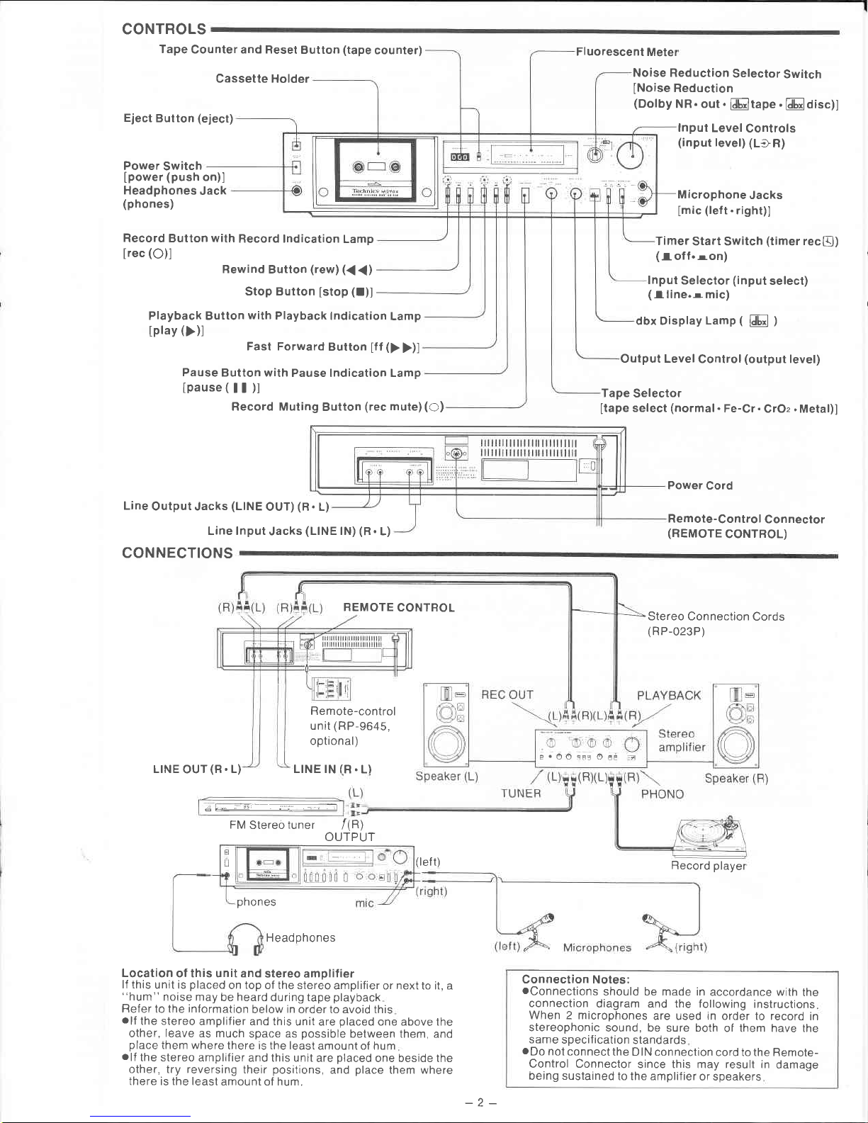
CONTROLS
Tape
Counter and Reset
Button
(tape
counter)
Cassette Holder
Eject
Button
(eject)
Power
Switch
Ipower
(push
on)]
Headphones
Jack
(phones)
Record Button with
Record lndication
Lamp
lrec
(O)l
Bewind
Button
(rew) ({
{)
Stop Button
[stop
(I)]
Fluorescent
Meter
Noise Reduction
Selector
Switch
INoise
Reduction
(Dolby
NR. out.
ldb,-ltape
.
klEloisc)l
lnput
Level
Controls
(input
level) (LlR)
Microphone
Jacks
[mic
(lef
t. right)]
Timer
Start Switch
(timer
recQ)
(Ioff.ron)
lnput
Selector
(input
select)
(lline.rmic)
dbx Display
Lamp
(
l,iL,l
)
Output Level
Control
(output
level)
Tape
Selector
[tape
select
(normal
.
Fe-Cr.
CrOz
.
Metal)]
Power
Cord
Remote-Control
Connector
(REMOTE
CONTBOL)
Button
with
Playback
lndication
Lamp
Fast Forward
Button
tff
(>
>)l
Pause
Button with
Pause lndication Lamp
lpause(ll)l
Record Muting
Button
(rec
mute)
(O)
Line
Output Jacks
(LINE
OUT)
(R.
L)
Playback
tplay
())l
Line
CONNECTIONS
lnput
Jacks
(LINE
lN)
(R.
L)
I . OO
=EE
O
EE :,
REMOTE
CONTROL
L|NE
OUT
(R.
L)
Remote-control
unit
(RP-9645,
optional)
LINE IN
(R.
L)
J!t4
FM
Stereo
tuner
(left)
phones
Headphones
Location
of this unit and
stereo amplilier
lf this
unit is
placed
on
top
of the stereo
amplifier or next to it, a
"hum"
noise may
be
heard
during tape
playback
Refer
to
the information
below
in
order to avoid this
.lf
the stereo
amplifier and this
unit are
placed
one above the
other,
leave
as much
space as
possible
between them, and
place
them where
there is the least
amount of hum
.lf
the stereo amplifier
and this unit
are
placed
one beside the
other, try reversing
their
positions,
and
place
them where
there is the least
amount of hum.
Stereo Connection
Cords
(RP-023P)
Record
player
Connection Notes:
.Connections
should be made in
accordance with
the
connection
diagram and the following
instructions
When 2 microphones
are used in order to record
in
stereophonic
sound, be sure both
of them have the
same
specif
ication
standards
.Do
not
connect
the DIN connection
cord to the Remote-
Control Connector
since this may result in
damage
being sustained
to the amplif ier
or speakers
/(R)
OUTPUT
-2-
Page 4
dbx
Noise Reduction
System
The dbx Noise Reduction
System
serves to
greatly
reduce the
noise
generated
during recording and
playback
across
the
whole audible
frequency
spectrum
(reduction
by more than
about 30 dB) and also to
improve
the linearity at high input
levels. As a result,
both
recording
and
playback
can be
performed
without impairing the wide
dynamic range of the
original sound
There are two
kinds
of dbx Noise Reduction
System:
type I and type
II. Type I is used for
open-reel
decks
and
industrial
applications
while Type
II, which is featured in
this deck, is used for cassette applications.
Features
1 Reduced
noise
over the whole audible frequency range
(more
than about
30
dB reduction).
2 The
noise is
compressed at a high recording level for
recording to enable recording with minimal
distortion and a
wide dynamic
range.
3.
The linear logarithmic
compression and expansion do not
make the
sound
quality
undergo change with level mis-
matching.
Principle of basic
operation
The dbx system works to
expand the dynamic range
by com-
pressing (encoding)
the signals
and then expanding
(decoding
them As shown in
the
figure,
the input
signal level is halved
during recording
onto the tape. During
playback
the halved
level is
doubled
to
restore the original
signal.
The figure
shows
that
high
signals are
greatly
expanded
(from
"+10d8"
to
"
+20" dB)
while low signals are
given
a
low
expansion
(
"
-40
dB"to"-80d8"
)
This results
in a
great
improvement in
the
dynamic range and
simultaneously in a
great
reduction in tape
h
iss.
lnput Encoding Decoding
Output
ttt4d44fi/u^r,1l{{
Tape hiss
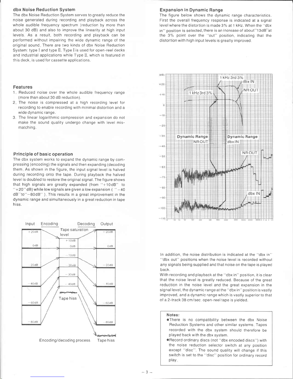
Expansion
in
Dynamic Range
The
figure
below shows the
dynamic
range
characteristics
First the overall
frequency
response is
indicated at a signal
level where
the distortion is made
3% al l
kHz.
When the
"dbx
in"
position
is selected,there
is an
increase
of about"l3dB"at
the 3%
point
over the
"out"
posrtion,
indicating
that the
distortion
with high input
levels is
greatly
improved.
ln addition, the
noise
distribution
is indicated
at the "dbx in"
"dbx
out"
positions
when the noise
level
is recorded without
any signals being supplied and that
noise
on the tape is
played
back.
With recording and
playback
at the
"dbx
in"
position,
it is
clear
that the noise level is
greatly
reduced.
Because
of the
great
reduction in
the noise level
and the
great
expansion in
the
signal
level, the
dynamic
range
at the
"dbx
in"
position
is vastly
improved,
and a dynamic
range
which is vastly
superior to that
ol a2-lrack
38 cm/sec. open-reel tape is
yielded.
Notes:
oThere
is no
compatibility between the dbx Noise
Reduction
Systems and other similar systems Tapes
recorded
with the
dbx
system should
therefore
be
played
back with
the dbx
system.
oRecord
ordinary
discs
(not "dbx
encoded
discs") with
the noise
reduction
selector
switch at
any
position
except
"disc".
The
sound
quality
will change if
this
switch is set to
the
"disc"
position
for
ordinary record
play
+2AdB
0dB
\
r
ape saru
level
alton
+zadB
0dB
rt0dB
0dB
2AdB
-z
'l0dB
2AdB
40d
B
30d
a
40d a
40d
B
60d
B
Tape
hiss
60d B
80d
B
80dB
Encoding/decoding
process
Page 5

"disc"
position
for
"dbx encoded
disc,'
play
This
unit
comes with
a
"disc"
position
on the Noise
Reduction
Selector
Switch for
playing "dbx
encoded
discs"
*.
When this
selector
switch
is
set to
the
position
given
in
the
figure
below,
"dbx
encoded
discs"
can
be
played
Noi se
Dolby
NR
Follow
the
procedure
given
below
(1)
Set
the recording
output
selector
swilch on the
stereo
amplif
ier
to the
"phono"
position
and set the input
selector
switch
or
tape
monitoring
switch
to the
"tape"
position.
(2)
Set this unit's input
selector to the
"line"
position
and set
the Noise
Beduction
Selector
Switch to the
"disc"
position.
(3)
Start operating the
turntable.
(4)
Adjust
the unit's lnput
Level
Controls
so that the
Fluores-
cent Meter
Scales def lect
to near
,,0
dB".
(5)
Adjust
the volume
using the volume
control
on the
stereo
amplifier.
Now
set the mechanism
to the
stop mode.
Some open-reel type
dbx
encoded
tapes
are now
available
f
rom music
stores These
tapes
can be
played
back
just
like
the
records
by
setting the Noise
Reduction
Selector
Switch to
the
"disc"
position
Notes:
olf
the
Noise Reduction
Selector
Switch is
set to the
"disc"
position
during
ordinary
tape
playback,
the
playback
sound
will not
be audible
olf
the
mechanism
is
operated
during
"disc"
play,
it will
work
but
the tape
playback
sound will
not
be audible.
lf the
Record
Button is
depressed
and the
deck
set to
the recording
mode,
the
decoded
sound
(the
now
restored
original
sound)will
be recorded
When
playing
back
this
sound,
set the
Noise
Reduction
Selector
Switch to
the
"out"
position
.lf
the
Record
Button is
depressed
when
you
are
listening
to records
with
the Noise
Reduction
Selector
switch
at the
"disc"
position,
the
sound
will
be cut
off
for
an instant
This
is not
a malfunction
aTo
record
"dbx
encoded records"
using
the
dbx Noise
Reduction
System, first
set the
Noise
Reduction
Selector
Switch to
the
"out"
position
and
start
recording
This
makes
it
possible
to record
in
the
encoded
state.
For
playback,
set
the
selector
switch
to
the
"tape"
position.
The
recording
level
should
be set
as
follows
First
set the
Noise
Beduction
Selector
Switch
to the
"disc"
position
and
adjust the
lnput
Level
Controls to
around
"-3dB"
so that
the Fluorescent
Meter
Scales
meter
pointers
do
not
exceed
"0dB',
at
peak
times.
Now
set the Noise
Reduction
Selector
Switch to
the
"out"
position
again
and
proceed
with
the
recording.
Sounds
monitored
while
recording
"dbx
encoded
records"
are
encoded (compressed)
sounds, not
decoded
sound
*
''dbx
encoded
discs
(records)"
dif f
er
f rom
ordinary
records
in
that
dbx noise
reduction
encoding (compression)
is
per-
formed
when
the
signals are
cut into
the records
During
play,
these
signals
pass
through
a
decoder
and the
original
sound
is restored.
This
makes for
a
virtually
noise-free
sound,
a
wide
dynamic
range
and
better music
reproduction
"Metal
tape"
magnetic
,,Metal
tape,, f
requency
response
characteristics
example
oda:
r6onwh/m
"Meta!tape"
Advantages
and magnetic
characteristics
of
,,Metal
tape"
1 .
Maximum
output level (MOL)
is
greater
at all frequencies.
2. Excellent
frequency
response
characteristics
at
high
input
level.
3
Wide
dynamic
range
at high
frequencies.
4.
Excellent
signal-to-noise
ratio
at high frequencies.
5
Low
distortion
Technological
developments
to
accommodate
"Metal
tape"
"Metal
tape" is
a totally
new
kind
of
high
performance
tape,
and conventional
cassette
tape
decks
cannot
sufficienily
bring
out
its
performance
potential.
Our company has
succeeded in
developing
the foilowing
technology
to
exploit the
advantages
of
"Metal
tape',
to its
fullest
extent.
1.
Development
of
the SX head
featuring
minimal
distortion with
high input
signal levels.
The
SX
head
employs
permalloy
and
it
features
a high
saturation
magnetic f
lux
density
and also
a superlative
wear
resistance.
lt was
developed
especially for
the new
breed
of
"Metal
tape".
2. Development
of
high-ef
f iciency
sendust
erase
head.
Sendust is
a material
with
a high
saturation
magnetic
flux
density
and it is
capable
of
extremely
eff icient
erasing
even
with
"Metal
tape"
with
a high maximum
output level
3.
The
power
in
the
bias
oscillator
circuit has
been
increased.
A word
about
"Metal tape"
Conventional
cassette
tapes
can
be broadly
classified
into
2
categories
according
to
the
magnetic
material
coated
on
the
tape
surface:
the
ferric-oxide
(
7
-FezOs)
type,
including
ordinary
LH
tape,
etc.;
and the
chrome-dioxide
(CrOz)
type,
including
XA
tape,
etc.
Continued
technological
advances
have
been
made
in
an
attempt
to
develop
these
tapes
to
a high level
of
performance,
but recently
there
has
been
a recognized
need
for
the
development
of a new
material
to improve performance
much
further
ln
response
to this
need,
',Metal
tape,'has
been
developed
as
a new
kind
of
tape,
employing
a magnetic
alloy
of
pure
iron (Fe)
as the
main
component
in
the
magnetic
substance.
ln
comparison
with
conventional
cassette
tape,
,,Metal
tape,,can
record
a
far
greater
amount
of information
at a high
density.
As
a result,
the maximum
output level (MOL)
has
been
improved
throughout
the
entire range,
and,
in
particular,
the frequency
response
characteristics
at high
levels
and the
dynamic
range
in
the
high range
have
been
greatly
improved.
This
means,
therefore,
that
a remarkable
improvement
of sound
quality
has
been
made
possible
(lt
should
be noted
that
the
tape
base
and
parts
of the
tape
other
than
the magnetic
substance
are
com_
posed
of the
same material
as
previously
used.)
-4-
Page 6

r-
CASSETTE
INSERT!ON AND REMOVA
oFollow
the numbered order
@
!iltt u
Notes:
.Be
sure
the open
part
of the cassette
f
aces
downward. lf it is
upside down, the Cassette
Holder can't be closed.
oBe
sure
to
close
the
Cassette
Holder
gently.
oBe
careful
not to
press
the Eject Button while the tape
is
moving, because
this will
stop
the operation and the Cassette
Holder
will
open
TAPE
SELECTOB
Before beginning a
recording,
check
to be sure that the Tape
Selector
is
set
to the type of tape that is
going
to be used.
Note that there
may
be a difference
in
sensitivity of 2
or 3 dB
depending on
the type of tape
To open
the
cassette
tid.
((})
lt[!t0
!
o oEl
PLAYBACK
.Follow
the numbered
order.
E
power
push
on
F
The
lndicator lights
when the
power
is
switched on. But
it has
nothing to do with the Noise
Reduction Selector Switch
E-
o
qo
iln n
o
m[0!c !
o o
Refer
to
"CASSETTE
INSERTION AND
REMOVAL" above.
Tape
Selector
Settino
B rand
Tape Type
normal
AMPEX GFAND MASTEBI
BASF PBOFESSIONAL I
FUJI
FXI
MAXELL UD
MAXELL UDXLI
SCOTCH
MASTER
I
SONY
UHF
TDK AD
c-60, c-90
c-60,
c-90
c-60, c-90
c-60, c-90
c-60, c-90
c-60,
c-90
c-60, c-90
c-60 c-90
CrO,
AMPEX
GHAND
MASTERII
BASF PBOFESSIONAL
II
FUJI FX
II
MAXELL
UDXL II
SCOTCH
MASTEF tr
TDK
SA
c-60
c-60
c-60
c-60
c-60
c-46,
C-60
Metal
FUJI
SB
MAXELL MX
SCOTCH
IVIETAFINE
SONY
METALLIC
TDK
MA
c-46,
C-60, C-90
c-46,
C-60,
C-90
c-46,
c-60, c-90
c-46,
c-60.
c-90
c-46,
C-60.
C-90
C
[[![!L]
tape
select
Fe-Cr
CrOz
normal
Metal
Refer to
"TAPE"
SELECTOR" above
Set
the Noise Reduction
Switch
to
"Dolby
NR" when
using the Dolby system and to
"dbx
tape" when using
the dbx system
Refer
to
page
3 and 4
for instructions
on
use at the "dbx
disc"
position
n
play
[[[!!! r-
o
For
private
listening
4=="-o
lrllll I
o d.gs
!
For
listen-
ing
with
speakers
':" ':l
'rf,
"!,
*
,"ri"
!!. !r!
stop
Notes:
.Note
that the
operation buttons will not fuction
until about
5
seconds
have
passed
after the
power
rs
turned
on
.Output
is
0.42 V
f rom
the Line
Output Jacks
when the Output
Level
Control on this unit is set to its maximum
position
and
the Fluorescent Meter
scales
indicate
0
dB
.No
playback
sound will be heard from
this unit if,
during
playback,
the
Output
Level
Control
is set to its minimum
position,
even though the
volume
control of
the
amplifier
to
which this
unit
is
connected
is
set
to its maximum
position
oWhen
listening through headphones, adlust the volume level
by using the
Output
Level
Control
of this unit
.Do
not
set the Timer Start Switch to
"on"
during
playback
E
Page 7

FORWARD
AND
REWI
.Follow
the numbered
order
ND
a
FAST
E
'3"
I
'ii,
"!'
Jl
-i'"
illr!
stop
'3'
l
;'
':r
'ri,
"i
:!
r[!!r
;'
'::
'ri,
!ril
stop
order.
RECORDING
E
tff:
a
Refer
to
"PLAY-
BACK"
@on
page
5 for the
selection
of Noise
Reduction
System.
Refer
to
"CASSETTE
INSERTION
AND
RE-
MOVAL
"Il,El,Et
on
page
5.
Caution:
Do not
push
the
Eject Button
during
the fast forward
or the rewind
operation
pushing
the
Stop Button.
Before
pushing
the Eject
Button,
be sure
to first
stop the tape
by
oFollow
the numbered
n-lllnlloosnlB
tape
select
Fe-Cr
Refer
to
"TAPE
normar
uru2
SELECToR"
,nlnt
I
d
oanl
B
input
select
II
line
mic
lf
the recording
is to
be made
by
microphone(s),
set
the lnput
Selector to the
"mic"
position.
lf
the
recording
is to
be made
from
equipment
connected
to the
Line
lnput
Jacks,
set the lnput
Selector
to
the
"line"
position.
lnput
Level
Controls are
each
separated into
two
parts
so that left
and right
channels
can
be
adjusted
separately.
The
outer
part
of the
controls is for
the
left
channel,
and
the inner
part
is for
the right
channel.
Irrrrrrrurrrrrrnrrrurrrrrrrrrrr
f)[ rrrrrrrrrrururrrrrrrrrr)l
$!r8r!*!t,tt8t!8,8t,!8!8&,t&t!ffi
!!!l!l!u!'l|lt!*{*}}1
20
fpr-FAFl 6
.
4
.
2
.
O
.
2OO. 6 I
.
,t!!!|lt8n,!r!!!8Bett!&er!!!,et8*&8te*tn!$|llltstrilll
n
lrrrrrrrrrrrrrrrrrrrrrrrrrrrrnrrrrO(
rrrrrrrrrrrrrrrrrrrrrrrrN
oMake
the
adjustment
so that the
Fluores-
cent Meter
scales
show
an illuminated
indication
up to "+6
dB"
when
the input
signal level
is maximum
.For
recording
of chamber music
(such
as a
string
quartet),
and
other music
in which
there is very
little
percussion
sound,
adjust
so that the level
is
slightly lower (to
an
iltuminated
indication
up to
"+3
dB")
Ittttrrrrrrrrrrrrrrr
IO
rrurrrrurrr)l
8'!r*86!!8888s'08&tXrX&88'trX&8ee<ii*i*{}t:}tt{i$t
"i
20
tm-n
6
.
4
.
2
.
o . 200,
6 8
.
o
lrrrurrrrrlrrrrrrf1|Onrrrrrrrrrrrr)l
.lf
the Fluorescent
Meter
scales
show
an
illuminated indication
of only up to
about "0
dB" when
a loud
sound is received,
the
recorded
results will
be rather noisy (with
a
poor
signal-to-noise ratio)
when recording
"dbx
encoded
records",
the
Fluorescent
Meter
Scales should
be
adjusted,
so as they
do not
exceed
the
"0
dB" level
at
peak
times.
Refer to
the
notes
on
page
4
about
Recording
of
"dbx
of
encoded
records,,
!8Xt,,r,88t8&rtrX8t8ttN&tr&t$&t8!!ffi
&t!!t!t'ttxx||&x
!rl
20
fP{Ml 6
.
4
.
Z
.
O , 200.
6 I
.
!8t$rE8{t8t,!tr8!&r*t,8rr!888&xtst,!!r!8xE!lNxl|t8t8t!
n
lrrrrrrrrrrrrrrrrrrrrrrrrrrrrrrrrrrrrrrrrllf)rrrrrrrrrrurrrrrrrrrrrrrrrrrr{l
olf,
conversely,
the
Fluorescent
Meter
scales
continuously
show
the illuminated
indication
up to
"+B
dB,"
the recorded
results
will
be rather
distorted
gEE
r-
-l-
I0
s|oe
t
lnllll
I
o
oE
TIMER
RECORDING AND PLAYBACK
.Follow
the numbered order
aConnections
to the
power
source
Stereo
tuner
AC
OUTLET
Timer
AC
socket
illltil
o orlt
B
Stereo
Amplifier
Recording
with
a
Timer
(Timer
of FM
broadcasts)
recording
la
Refer to
..CASSETTE
INSERTION
AND RE-
MOVAL.''
E, E,
Et ON
page
5
Tab
Cellophane
L---'"P",
-
w@
Refer to
..ACCIDENTALERASE PREVEN-
TION," on
page
1.
o
oE
ING
.Follow
the numbered
order.
@
Refer
to
"CASSETTE
INSERTION
AND RE-
MOVAL."
II,
EI, Et
ON
page
5.
Use the
"CrOz"
position
for
erasing
normal,
Fe-Cr
and
CrOz tapes.
Use the
"Metal"
position
to
erase
"Metal
tape".
,t
pdLse
o{Frl
[[!nrr
rec
power
push
on
E
E
+
olo
dc
It!
MAINTENANCE
.Follow
the numbered
order
Cleaning
the
head
section
Because
the Head Assembly, Pinch
Roller
and
the
Capstan are
in
constant contact
with
the
moving
tape,
parts
will decrease the sound
quality
They
should be cleaned
with a
Cotton
Swab
af ter every
10
hours
of
Removethe
cassette
lid
REC/PB Head
Capstan
Pinch
Roller
Tape
Guide
dirt or residue from
the tape on these
use. as described below:
g

sr
a
o)
@
r{
(\t
cn
(v)
(I}
FI
E
uJ
@
=
f
z
ul
o
6
=
E
z
fr
-{-3
Q
Ouiri=uu'l lr
H?euHjnsc
JtI=3EHfiH=
z
e5
FE.
gaHlsEE:5EE
T-
ll)
.s
CP
b
(u
5
e6
o9
o<
!Ar
3l
,xl
.Jl
.el
:al
d-l
dl
vl
5t
utl
;al
32
xl
ol
crl
_{t
e2
E
o
o
o
(r
-at,
o)
E
o
o
=
o
lE
c
d
,.E
o
f
,.E
E
c
i(!
)O
i9
,c
?E
!6
,f
2o)
ie.s
:
o;
,=-'
;*28
EPEE
icEo
-'-
G
=
=o-
-o>
9.6
.s
o
6fYE
oEH.9
P
g_'E
o
tr
TIJ
o
z
o
.q
E
o
E
E
E
(U
o
.u)
o
(U
c
o
l
E
o
o_
o
F
(E
o
(r,
(E
o
+
F
z
F
(r
o
(L
SEAEEF
E
BEi;E
.-E
tTEfiEHE;i;Ef;
Eis
::;EE5€gEEE:
AgE*5EE;E;i$EE
o
z
J
u.l
o
o
=
(J
z
o
o-
t
fl
\,
t
E
j
o
tr
F
o
o
.)d
FJ-.
r\
o
f
G
o
=
E,
uJ
lr,l
o
tr
UJ
o
F
o.
IJJ
O=r
oF
Ze
=
9ti;
-
F
Eg LlJ
-.:
'i
iifr;$
fi
sf
3
q
=-89*
O
3HU
F
o
f
o
(
$
$
q)
*
G
E
o
E
0)
go
G
o
l.-
o
a
!l)
o
\
q)
s
q
s
o
E
o
o
G
(4
as
-3s
e
g
9Eor
6
::€E 3
HE,E
E
B
g3
E,E :
=5
ob
S
E iue
:
@ae
I
s
(t=
f,
'b
!
E H,E E
O
*o
^
*
8E
3:_ i
> o ,.r.E
E
=O_C,r-
ESE='g
(EU)=x^
o.-c<6
d
o
=
o
o
o-
o
-c
.s
L
o
=
o
tE
:
 Loading...