

Page 1

Service Manual
TOP NEXT
AD0102028C2
Cassette Deck
l RS-DV250
AR-2 Mechanism series
Colour
(S)..........Silver Type
Area
(E)..........Europe.
© 2001 Matsushita Electric Industrial Co., Ltd. All rights reserved. Unauthorized copying and distribution is a violation of law.
@
TOP NEXT
http://servis-manual.com/
Page 2

5 Service Mode Function of Cassette
Mechanism
TOP PREVIOUS NEXT
This unit is equipped with a service mode function of cassette mechanism, so that if the unit operates
incorrectly, the fault displayed using an error code on the FL display of the Tuner/Amplifier (SAEH770). The system control IC and FLdisplay are part of the Tuner/Amplifier so make sure the
system has been connected properly before using this function. Use this function during maintenance
to check faults of items below.
5.1 Cassette tape to be prepared
5.2 Selecting service mode
5.3 Deck 1 mechanism check
5.4 Deck 2 mechanism check
5.5 Exiting service mode
@
TOP PREVIOUS NEXT
http://servis-manual.com/
Page 3

5.1 Cassette tape to be prepared
TOP PREVIOUS NEXT
l
Metal tape:
Recorded music tape with only one erasure prevention tab intact./(use middle portion of tape)
l Normal tape: /CrO2 tape:
Recorded music tape with both erasure prevention tabs intact./(use middle portion of tape)
@
TOP PREVIOUS NEXT
http://servis-manual.com/
Page 4

5.2 Selecting service mode
TOP PREVIOUS NEXT
1.Turn on the power to the unit.
2.Make sure that no tape is inserted in the cassette deck. (Service mode cannot be selected with a
tape inserted in the cassette deck.)
3.Press the DOLBY NR button for about 2 seconds, and keep pressing it, also press the STOP
button for about 2 seconds. Refer to Fig. 5-1.
Fig. 5-1.
@
TOP PREVIOUS NEXT
http://servis-manual.com/
Page 5
5.3 Deck 1 mechanism check
TOP PREVIOUS NEXT
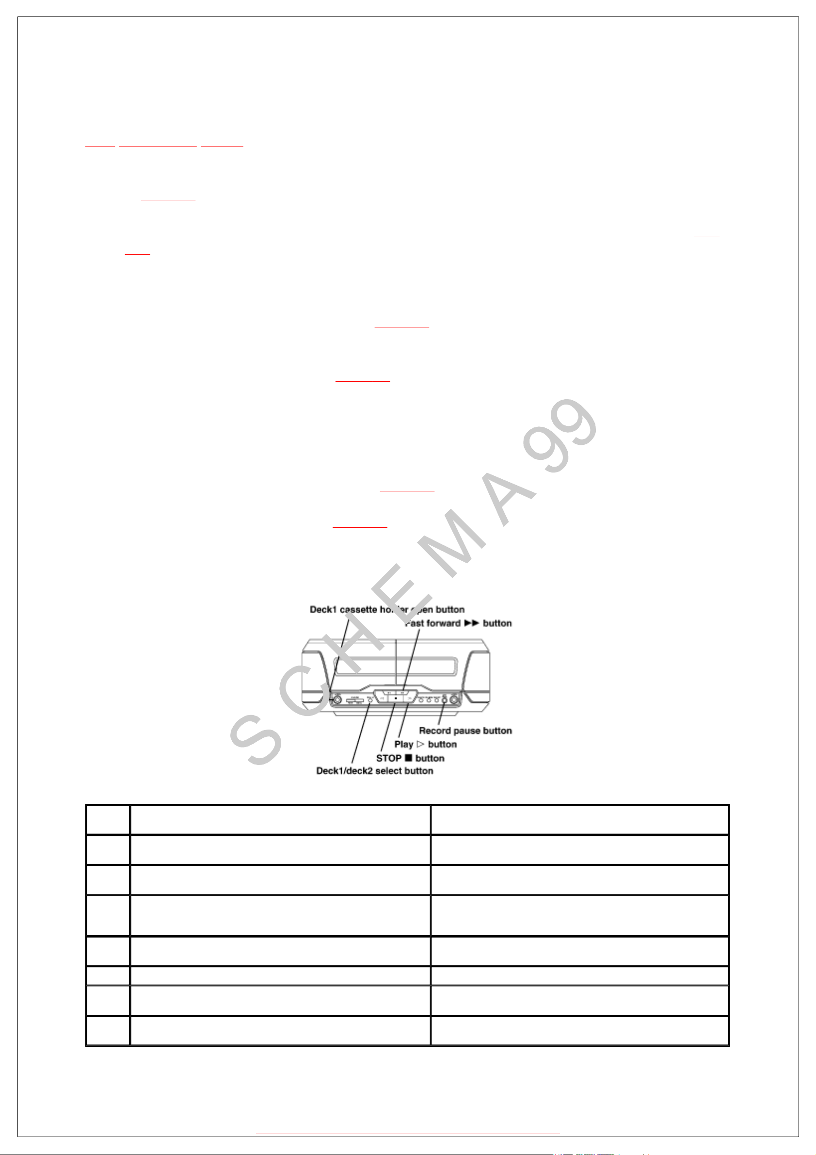
1.Press the Deck 1/deck 2 select button to change the flashing Deck 2 indicator to Deck 1. Refer
to Fig. 5-2. /(No change required if Deck 1 indicator already flashing.)
2.Press the Deck 1 cassette holder open button to open the Deck 1 cassette holder. Refer to Fig.
5-2.
3.Insert a CrO2 tape into the Deck 1 and close the cassette holder.
4.Press the Fast forward button. Refer to Fig. 5-2. /(Tape fast forwards for about 2 seconds then
stops.)
5.Press the PLAY button. Refer to Fig. 5-2. /(After TPS operation and check, the tape stops.)
6.Open the Deck 1 cassette holder and replace the tape with a normal tape.
7.Close the Deck 1 cassette holder.
8.Press the Record pause button. Refer to Fig. 5-2. /(No record operation.)
9.Press the STOP button. Refer to Fig. 5-2. A mechanism error code is displayed. Refer to Table
5-1. Each time the STOP button is pressed, the fault items are displayed in sequence.
Fig. 5-2.
Table 5-1.
FL
display
H01 Cassette deck does not operate correctly. Faulty cassette deck mechanism mode detect switch (Deck 1: S951,
H02 Unit does not record or the unit goes into recording mode even when the
erasure prevention tabs have been removed from the cassette.
H03 Tape does not play even when the tape deck play button is pressed.
The motor operates when the tape deck play button is pressed even if
cassette is loaded in the deck.
H06 Cassette deck does not detect CrO2 tape. Faulty CrO2 tape detect switch (Deck 1: S953, Deck 2: S973)./(Check
H07 Cassette deck does not detect Metal tape. Faulty Metal tape detect switch (S976). (Check and replace)
F01 When the tape play button is pressed, tape advances only slightly and
then stops.
F02 TPS (tape program search) does not work. Faulty TPS signal detection or faulty plunger control. /(Check and
Symptom Cause
Deck 2: S971), plunger and capstan motor. /(Check and replace)
Faulty erasure prevention tabs detect switch (S974, S975) or shortcircuit. (Check and replace)
Faulty tape detect switch (Deck 1: S952 Deck 2: S972) or short-circuit.
(Check and replace)
and replace)
Reel pulse error (Faulty Hall IC). (Check and replace)
replace mechanism control IC)
http://servis-manual.com/
Page 6

5.4 Deck 2 mechanism check
TOP PREVIOUS NEXT
1.Press the Deck 1/deck 2 select button to change the flashing Deck 1 indicator to Deck 2. Refer
to Fig. 5-3.
2.Press the Deck 2 cassette holder open button to open the Deck 2 cassette holder. Refer to Fig.
5-3.
3.Insert a metal tape into the Deck 2 with an intact erasure prevention tab on the right side.
4.Close the Deck 2 cassette holder.
5.Press the Fast forward button. Refer to Fig. 5-3. /(Tape fast forwards for about 2 seconds then
stops.)
6.Open the Deck 2 cassette holder and turn over the metal tape. (intact erasure prevention tab on
the left side.)
7.Close the Deck 2 cassette holder.
8.Press the Rewind button. Refer to Fig. 5-3. /(Tape rewinds for about 2 seconds then stops.)
9.Open the Deck 2 cassette holder and replace the metal tape with a CrO2 tape.
10.Close the Deck 2 cassette holder.
11.Press the PLAY button. Refer to Fig. 5-3. /(After TPS operation and check, the tape stops.)
12.Open the Deck 2 cassette holder and replace the CrO2 tape with a normal tape.
13.Close the Deck 2 cassette holder.
14.Press the Record pause button. Refer to Fig. 5-3. /(No record operation.)
15.Press the STOP button. Refer to Fig. 5-3. A mechanism error code is displayed. Refer to Table
5-1. Each time the STOP button is pressed, the fault items are displayed in sequence.
Fig. 5-3.
http://servis-manual.com/
Page 7

5.5 Exiting service mode
TOP PREVIOUS NEXT
1.Press the STOP button for more than 5 seconds (Diagnostic contents stored in memory for
both Deck 1 and 2 are erased.)
2.Remove the cassette tape from the cassette holder.
3.Turn off the unit.
@
TOP PREVIOUS NEXT
http://servis-manual.com/
Page 8

13.3 Head azimuth adjustment (Deck 1/2)
TOP PREVIOUS NEXT
1.Connect the measuring instrument as shown in Fig. 13-1.
2.Replace azimuth screws for both forward and reverse directions after removing the screwlocking bond left on the head base. (Supply part No. of azimuth screw: RHD17015 )
3.Playback the azimuth adjustment portion (8 kHz, -20 dB) of test tape (QZZCFM). Adjust the
azimuth screw until the outputs of the L/R ch are maximized. Refer to Fig. 13-2. Make sure
that thedifference in the peak level between the left and right channels does not exceed 0.5 dB.
4.Perform the same adjustment in reverse playback mode.
Check of the level difference forward and reverse directions.
5.Playback the playback gain adjustment portion (315 Hz, 0 dB) of test tape (QZZCFM). Check
if level difference between forward and reverse direction is within 1.5 dB.
6.After the adjustment, apply screw lock to the azimuth screw.
Fig. 13-1.
Fig. 13-2.
@
TOP PREVIOUS NEXT
http://servis-manual.com/
Page 9

13.4 Tape speed adjustment/(Deck 1/2)
TOP PREVIOUS NEXT
Note:
When connecting the unit to other system components for test, short the section between the test
point TP604 and TP609 and turn on the entire system. (The unit is set to the TEST mode, and either
Deck 1 or Deck 2 indicatorwill blink.)
Normal speed (Standard value: 3000 ± 45 Hz)
1.Connect the measuring instrument as shown in Fig. 13-3.
2.Playback the middle portion of test tape. (QZZCWAT)
3.Adjust VR801 (Deck 1) and VR803 (Deck 2) for output value shown below. (For adjustment
point, refer to Fig. 13-11. )
Adjustment target: 3000 ± 15 Hz (Normal speed)
Standard value: 3000 ± 45 Hz (Normal speed)
Fig. 13-3.
Note:
When the unit is finished for adjusting, disconnect the short section between TP604 and TP609 .
@
TOP PREVIOUS NEXT
http://servis-manual.com/
Page 10

14.1.1 Connection Diagram Between the Mechanism Ass’y and Power
Supply/(MOTOR and Plunger)
TOP PREVIOUS NEXT
@
TOP PREVIOUS NEXT
Fig. 14-1.
http://servis-manual.com/
Page 11

14.1.2 Detail View of EJECT Lever /(EJECT
lever fixed by rubber band, Plunger rib
operation)
TOP PREVIOUS NEXT
Fig. 14-2.
@
TOP PREVIOUS NEXT
http://servis-manual.com/
Page 12

DECK1
Lch
PLAYBACK
HEAD
Rch
DECK2
Lch
R/P HEAD
Rch
ERASE
HEAD
IC103
BA7755AF
R/P SELECT
C301
ERASE CURRENT
CHECK POINT
R107
10K
(8.9V)
0V
G
S
0V0V
Q103
Q104
0V0V
SGD
R131
330K
1 2 4
16V470
R313
1
9.6V 0V
C302
100V2.2
C303
6800P
TP302TP301
0V
(8.9V)
678
3
N
MAIN CIRCUIT
A
CP101
1
2
3
4
5
(0.7V)
D
680P
C103
Q105,106
2SD1819ARTX
MUTING
(0.7V)
10K
R108
CP102
1
2
3
4
5
R132
27K
6V
5
0V
(9.5V)
1.8K
R302
(0.7V)
R301
Q101
2SJ164RTA
HEAD SELECT
(REC:ON)
680P
C102
680P
C101
Q105
0V
R143
100
Q103,104
2SJ164QTA
HEAD SELECT
(PLAY:ON)
0V
0V
0V
D301
10K
MA111TX
Q306
DTC144EUT106
BIAS OSC CONT.
0V0V
SGD
(0.2V)
9V
330K
R105
0V
0V
Q106
R106
330K
(0.2V)
Q102
2SJ164RTA
HEAD SELECT
(REC:ON)
R144
100
C144
470P
9V
G
D
S
0V0V
C116
470P
R102
R104
L301
4
6
Q302
2SD1328STXRA
SWITCHING
(REC:ON)
R303
2.2K
C305
50V0.1
(0.6V)
C143
470P
5.6K
100K
R305
0V
18K
3
25
1
C125
3300P
R101
5.6K
C115
470P
IC101
CXA1998BQT6
R/P EQ AMP
R111
82
C111
6.3V47
R141
100
R142
100
680P
C104
C110
0.018
C112
6.3V47
82
R112
1K
R110
C124
25V4.7
C114
C113
50V2.2
50V2.2
C126
3300P
L302
100 H
C306
C304
16V100
0V
:POSITIVE VOLTAGELINE : PLAYBACK SIGNAL LINE: RECORDING SIGNAL LINE
C123
25V4.7
C119
C308
C310
50V1
10K
10K
3300P
0.01
(0.8V)
0V
AGC
GAIN
AGC
AGC
GAIN
R310
4.7K
R311
4.7K
C120
R309
C309
9.6V
40K
40K
50V1
4.7K
6.3V47
RECEQ
R158 22K
4.7K
R138
C150
100K
R103
10V100
470P
C130
C131
16V100
R113
12K
1.2V
R109
1K
2.6V
38
C109
0.018
2.6V
39
1.3V
40
0V
41
0V
42
0V
43
0V
44
1.3V
45
2.6V
46
2.6V
47
1.2V
48
27K
R114
R133 33K
R130 4.7M
C139 6.3V47
A
B
9.6V
9.5V
Q303
(0.1V)
R307
(0.1V)
2.2
9.5V
0.039
Q303,304
2SD1450RSTA
BIAS OSC
Q305
DTC144EUT106
BIAS OSC CONT.
22
R119
C117
22
R118
C129
R117
10V22
1K
RFS
210K 210K
210K
210K
1 2 3 4 5 6 7 8 9 10 11 12
(1.6V)
C307
1000P
(0.6V)
0V
0V
(0.6V)
0V
0V
Q304
15K
R304
(0.6V)
0V
330P
C140
16V10
4.5V9V9V 4.5V 4.5V 4.5V 4.5V 0V5V 0V
IREF
MUTE
5V 0V 4.5V 4.5V 4.5V 4.5V 4.5V 8.6V 5V0V
R308
C323
1000P
1K
R306
33K
C311
(0.7V)
0V
0.01
0V
0V
(0.2V)
C118
330P
R154
2.7K
Q301
2SD1819ARTX
BIAS OSC CONT.
SHIFT
REGISTERS
PBEQ
CTL
REQEQ
CTL
20K 20K
AMSRECEQ
4.7K
R127
C138
0.047
R135
6.8K
R134
3.9K
2.2K
R137
2.2K
R136
R153
2.7K
C137
50V0.1
R157
22K
252627282930313233343536
LATCHES
20K 20K
100K
R125
D102
MA111TX
D101
MA111TX
C132
A
B
C
470P
2437
23
22
21
20
19
18
17
16
15
14
13
5V
5V
(9.6V)
0.1V
(0.1V)
9.6V
(0.2V)
9.6V
(0.2V)
5V
(5V)
0.2V
R120
C135 50V1
100K
C136 50V1
Page 13

E
D
F
CNRMO
R725
2.2K
R726
2.2K
470P
C134
0.1
470P
C133
C142
10K
10K
R122
R121
Q107
DTA143EUT106
R/P SELECT
(0.2V)
9.6V
R730
A
B
9.6V
0V
(9.5V)
2.2K
9.6V
:POSITIVE VOLTAGELINE : PLAYBACK SIGNAL LINE: RECORDING SIGNAL LINE
5V
12K
R2133KR215
C221
50V0.68
C207
270P
R209
C203
1K
25V4.7
R23722R220
22
0.01
C241
5V
C204
25V4.7
R210
1K
L201
C219
16V100
IC201
CXA1552M-T4
DOLBY B NR
C208
270P
L202
R211
10K
C211
1500P
R212
10K
R218
2.2K
R217
C220
2.2K
1 2 3 4 5 8
10V470
680P
C239
4.8V 9.6V 4.7V 4.7V 4.6V 4.7V 0.4V 4.8V
ATT2
ATT2
4.8V 4.7V 1.2V 4.7V 0.4V 4.8V4.6V
C205
50V1
ON/OFF
ATT1
ATT3
ATT3
ATT1
DOLBY
ON : 0V
R/P
(0V)
R221
100
6 7
SC DET
SC DET
25V4.7
C218
50V0.1
101116
C225
C213
25V4.7
912131415
DOLBY
Lch
R2301KR223
10K
C223
C
25V4.7
BA
R216
12K
3K
R214
C222
50V0.68
B
PLAYBACK
GAIN ADJ.
(DECK1/Lch)
A
PLAYBACK
GAIN ADJ.
(DECK1/Rch)
C214
25V4.7
VR101
20K(B)
5.6K
R147
DOLBY
Rch
VR104
20K(B)
5.6K
R150
PLAYBACK
GAIN ADJ.
(DECK2/Lch)
IC102
MC14066BFEL
DECK 1/2 SELECT
VR103
20K(B)
5.6K
R149
C212
1500P
VR102
20K(B)
5.6K
R148
PLAYBACK
GAIN ADJ.
(DECK2/Rch)
680P
C240
1 2 3 4 5 6 7
9.6V 9.6V
50V1
C141
C206
(0.1V)
R219
10K
R224
B
A
0V0V0V 0V
(0.1V)
R222
1K
R231
(0V)
5V
Q202
DTA143EUT106
ENC/DEC SELECT
47K
R140
(9.6V)
0.1V
18K
50V1
100
(5V)
0V
(9.6V)
0.1V
0V0V0V 0V9.6V
C217
50V0.1
C226
25V4.7
891011121314
R139
47K
R152
100K
5V
5V5V
Q201
DTA143EUT106
DOLBY ON/OFF
0V
I
J
100K
R151
Page 14

MAIN CIRCUIT
A
Q807
2SB621ARSTA
SOLENOID DRIVE
10.3V
10.3V
0V
MECHANISM CIRCUIT (DECK1)
B
R952
820
R953
39K
IC951
0N2180RLC1
PHOTO
INTERRUPTER
3 4
1 2
D951
MA165TA
SOLENOID
S951
(MODE)
R806
10K
S953
:POSITIVE VOLTAGELINE
5V
DL EK
Q809
DTC143EUT106
SOLENOID DRIVE
R802
R823
560
560
10.2V
0V
CS951
S952
(CrO2)
(HALF)
5V
0V
1
2
3
4
5
6
7
8
9
CAPSTAN
Q810
DTC143EUT106
SOLENOID DRIVE
0V
MOTOR
(DECK1)
M
Q808
2SB621ARSTA
R812
560
R803
10K
SOLENOID DRIVE
10K
R811
10.3V
Q805
DTA143EUT106
MOTOR DRIVE CONT.
R814
470
0V
P
S
F
Q
10.3V
VR801
5K(B)
5V
0V
5V
TAPESPEED
ADJ.(DECK1)
10.3V
0V
5V
CAB
10.3V
R824
560
10.2V
0V
Q803
2SD592ARSTA
MOTOR DRIVE
9.8V
0V
CP901
1
2
3
4
5
6
7
8
9
2.2
R818
CP306
1
2
A
3
R805
B
3.9K
4
MECHANISM CIRCUIT (DECK2)
C
50K
4.7K
4.7K
S972
S974
(R.REC.INH.)
D971
MA165TA
SOLENOID
50K
(HALF)
5V
50K
R973
R972
820
Z971
1 2 3 4 5 6 7
25K
50K
50K
4.7K
4.7K
S971
S975
(MODE)
(F.REC.INH.)
IC971
0N2180RLC1
PHOTO
INTERRUPTER
12
34
25K 25K
39K
S976
H
G
B
R820
3.9K
A
5V
Q806
DTA143EUT106
MOTOR DRIVE CONT.
Q804
2SD592ARSTA
VR803
5K(B)
MOTOR DRIVE
TAPESPEED
ADJ.(DECK2)
2.2
5V
5V
470
R813
0.8V
0V 0V
10.3V
0V
1
2
3
4
5
A
6
B
7
C
8
D
9
2)
S973
(CrO
(METAL)
D
B
C
CAPSTAN
MOTOR
(DECK2)
M
A
CP902CS971
1
2
3
4
5
6
7
8
9
CP305
1
2
A
3
R810
R808
B
10K
4
Page 15

:POSITIVE VOLTAGELINE : PLAYBACK SIGNAL LINE: RECORDING SIGNAL LINE
5V
0.01
C707
D706
MA111TX
L701
10 H
C702
C706
50V3.3
Q706
DTC114EUT106
RESET SIGNAL
GENERATOR
6.3V100
0.01
C701
0V
D705
MA111TX
R711
100K
5ms. 2V/DIV.
16ms.
T
T 16ms.
R737 10K
R736 10K
5V
0.01
C705
0V
T 16ms.
R712 68K
R718 68K
R701 10K
R702 10K
4.8V
0V
4.8V
0V
3.6V
AC E
BD
0V
D701
MA111TX
5V5V0V5V1.4V
1 2 3 4 5 6 7 8 9 10 11 1213 14 15 16 17 18 19 20 21
SS
AV
VREF
KEY1 VCC
KEY2
3V
0V
PHOTO1 T
4142 222324252627282930
5V0V5V
2.9V
0V(5V)
LMT
T 16ms.
AD SW
0V
2.7V
PL1
PHOTO2 T
JEDG
R738
1K
D710
MA111TX
100
R745
D707
R710 1K
L702
2.2V
2.5V
0.5V
1.6V
1V
M1
CS
CLK
REQ
HALT
NC
LED CNT
5V
STOP : 0V
DATA IN
METAL2
4.8V
DATA OUT
0V
M2
ENC/DEC
DOLBY ON/OFF
ECS
NC
NC
31323334353637383940
0V
0V
0V
(5V) 0V
MA4051MTA
CRO2 2
PL2
0V0V0V
SS
V
A LATCH
5V
R724 1K
R723 1K
0V
5V5V2V
RESET
REV LED
FWD LED
TPS
A CLK
ADATA
5V
0V
0V
R704
4.7K
F=8MHz
XIN
HALF1
5V
R747
R727
2.3V
5V
1K
4.7K
0V
XOUT
MODE
5V
Q701,703
2SD1819ARTX
INTERFACE
1K
R744
0.1V
Q701
1.2V
P-P
R722
100
VSS
IC701
CRO2 1
M38503M2406F
SYSTEM CONTROL
R703
5.6K
1.9V
0V
R708
4.7K
13
X701
(8MHz)
F=8MHz
0V
4.7K
R729
Q703
2
2.4V
P-P
R735 4.7K
R721 4.7K
R732 100K
22K
R741
D708
MA111TX
1.8V
R743
0V
R705
47K
D709
0.2V
0.6V
0V
R728
Q702
2SD1819ARTX
INTERFACE
F
H
I
47K
MA111TX
10K
CN901
1
A
B
C
D
E
2
3
4
5
6
7
8
R232
10K
F
G
5V
10.3V
Q602
2SD2144STA
POWER SUPPLY
10.3V9.6V
10.3V
C602
16V220
CBAFIOJKLMNGH
R630
0.33
R602
0.33
330
R604
R609
C605
100
16V220
D651
MA165TA
D652
MA165TA
9.6V
Q604
2SC3940AQSTA
REGULATOR
5.7V
C603
16V47
+
10V
EDABC
A
B
C
D
E
F
PQR
S
R603
C604
D606
0.01
MA4056MTA
R606
(D.GND)
TP609
Rch
OUT
CT.GND
10
1.5K
R632
47K
Lch
OUT
TP604
RchINLch
EARTH
TERMINAL
D
A.GND
W601 E1
CN601
1
F
G
H
I
J
IN
SYNC
2
NC
3
NC
4
CS
5
+B(10V
6
D.GND
7
SCLK
8
DATA
9
DECK REQ
10
NC
11
TAPERch OUT
12
TAPELch OUT
13
RS A.GND
14
TAPERch IN
15
TAPELch IN
16
NC
17
A.GND
18
NC
19
NC
20
NC
CIRCUIT
)
To
SOUND PRCESSOR
(SH-EH770) &
CD CHANGER
(SL-EH770)
9.4V5V
Page 16

OPERATION CIRCUIT
E
:POSITIVE VOLTAGELINE
:PLAYBACKSIGNAL LINE
1
2
3
4
5
6
7
8
FW901
S912
(
DECK 1/2
S911
(
REV MODE
S910
(
S909
(
S915
(
OPEN
S914
(
COUNTER
RESET
S913
(
COUNTER
DISPLAY
S907
( )
5V
S906
( )
S905
(
DOLBY NR
S904
(
REC PAUSE
S903
(
TAPEEDIT
S901
(
OPEN
S900
(
3.3K
R906
)
2.2K
R905
)
1.8K
R904
)
1.5K
R903
1.2K
R902
R901
R900
1K
820
)
)
)
)
2.2K
R911
)
)
)
)
)
R910
R909
R908
R925
R924
1.8K
1.5K
1.2K
1K
820
Q901
DTA143EUT106
LED DRIVE
R915
680
R917
MA111TX
680
STOP : 0V
5V
5V
D904
0V
0V
0V
R916
330
5V
R914
330
Q902
DTC143EUT106
LED DRIVE
D907
SML79455C
(
)
D905
SML79455C
)
(
Q903
DTC143EUT106
LED DRIVE
0V
0V
2.6V
0V
4.2V
Q904
DTC143EUT106
LED DRIVE
0V
MAIN CIRCUIT
A
A
47K
47K
47K
C215
R233
16V10
B
C
D
E
F
G
100
R234
100
IC202
MC14066BFEL
SIGNAL CONT.
Q108
DTC143EUT106
SWITCHING
(5V) 0V
C216
16V10
8.3V(0V)
R226
R208
4.7V 8.3V
8 9 10 11 12 13
7 6 5 4 3 2 1
8.3V
(0V)
22K
R126
R225
R207
47K
9.6V
(0V)
9.6V4.7V 4.7V 4.7V
14
 Loading...