

Page 1

MULTIMEDIA
MONITOR
USER’S MANUAL
Page 2
Important Information
WARNING
To reduce the risk of fire or shock
hazard, do not expose this TV to
rain or moisture.
WARNING
RISK OF ELECTRIC
SHOCK DO NOT OPEN
This symbol indicates
"dangerous voltage" inside the
product that presents a risk of
electric shock or personal injury.
Refer to the identification/rating label located on the back panel of your product
for its proper operating voltage.
FCC Regulations state that unauthorized changes or modifications to this
equipment may void the user’s authority to operate it.
If fixed (non-moving) images are left on the screen for long periods, they may
be permanently imprinted on the screen. Such images include network logos,
phone numbers, and video games. This damage is not covered by your
warranty. Extended viewing of channels displaying these images should be
avoided.
Cable TV Installer: This reminder is provided to call your attention to Article 820-
40 of the National Electrical Code (Section 54 of the Canadian Electrical Code,
Part 1) which provides guidelines for proper grounding and, in particular,
specifies that the cable ground shall be connected to the grounding system of the
building as close to the point of cable entry as practical.
To reduce the risk of electric shock, do not remove
cover (or back). No user serviceable parts inside.
Refer servicing to qualified service personnel.
This symbol indicates
important instructions
accompanying the product.
PRODUCT REGISTRATION
Please fill out the product registration card and return it immediately.
Returning the card allows us to contact you if needed.
Keep your sales receipt to obtain warranty parts and service and for proof of
purchase. Attach it here and record the serial and model numbers in case you
need them. The numbers are located on the back of the player.
Model No.____________________________________________________
Serial No. ____________________________________________________
Purchase Date:________________________________________________
Dealer/Address/Phone: _________________________________________
_____________________________________________________________
Page 3

Table of Contents
Connections & Setup ....................................................................... 5
Connecting Components to your Monitor .................................................. 6
Antenna/Cable In............................................................................................. 6
Audio/Video/S-Video Inputs (Input1, Input2, Input3)........................................7
Audio/Component Video Inputs .......................................................................8
Selected Video Outputs....................................................................................8
Audio Output ..................................................................................................9
Optional Component Connection Examples ..................................................10
Monitor and a VCR..................................................................................10
Viewing the VCR Input Channel ................................................................... 10
Monitor, VCR and a Satellite Receiver .....................................................11
Viewing the Components ............................................................................. 11
Monitor, VCR, Satellite Receiver, and a DVD Player ................................12
Viewing the Components ............................................................................. 12
A/V Receiver & Speakers.........................................................................13
(S)VGA Video Inputs –(S)VGA1, (S)VGA2.......................................................14
(S)VGA1 Input Connection Examples ......................................................15
Viewing the (S)VGA1 Input........................................................................... 15
(S)VGA2 Input Connection Example........................................................16
Viewing the (S)VGA2 Input........................................................................... 16
Front Inputs ...................................................................................................17
USB Inputs/Output ........................................................................................17
Setting Up the Monitor.............................................................................18
First Time Setup ........................................................................................18
The Point and Select Navigation Method .......................................................19
Set the Time...................................................................................................19
Auto Channel Search.....................................................................................20
Set the VCR1 Channel (Autotuning) ..............................................................21
Set the VCR2 Channel (Autotuning) ...............................................................22
Set the DVD Channel (Autotuning) ................................................................23
Set the SAT/CABLE Channel (Autotuning).......................................................24
Label the Channels ........................................................................................25
What Now?..............................................................................................25
1
Page 4

Table of Contents
Using the Remote .......................................................................... 27
Remote Buttons........................................................................................ 28
Using the INPUT button ................................................................................29
Programming the Remote.........................................................................29
Testing the Remote ........................................................................................29
Programming the Remote ..............................................................................30
Using Automatic Code Search.................................................................30
Using Direct Entry...................................................................................30
Using the Remote to Control a Device...........................................................31
Modes of Operation.......................................................................................31
Front Panel...............................................................................................31
Remote Control Codes .............................................................................32
2
Page 5

Table of Contents
Menus and Features....................................................................... 33
Menus and Control Panels........................................................................34
Menus ...........................................................................................................34
Exiting a Menu ........................................................................................34
Control Panels ...............................................................................................35
Sliders .....................................................................................................35
Numeric Entry.........................................................................................35
Choice Lists.............................................................................................36
Audio Menu.............................................................................................36
Picture Quality Menu...............................................................................37
Screen Menu............................................................................................38
Closed-Captioning.........................................................................................38
Channel Menu ......................................................................................... 39
Time Menu............................................................................................... 40
Parental Controls and V-Chip....................................................................41
V-Chip TV Rating Limit ..................................................................................42
The Ratings Limits Screen........................................................................42
Blocking Age-based Ratings ....................................................................43
Viewing Age-based Ratings .....................................................................44
Blocking Specific Content Themes...........................................................44
Viewing Specific Content Themes............................................................ 45
V-Chip Movie Rating Limit.............................................................................46
Blocking Movie Ratings...........................................................................46
Viewing Movie Ratings............................................................................ 46
V-Chip Unrated Program Block......................................................................47
Channel Block ...............................................................................................47
Front Panel Block ...........................................................................................47
Lock/Unlock Parental Controls.......................................................................47
PIP (Picture-in-Picture) Operation ............................................................ 48
PIP Buttons ....................................................................................................48
Tips for Using the PIP Buttons........................................................................48
Channel Marker ....................................................................................... 49
3
Page 6

Table of Contents
Reference....................................................................................... 51
Troubleshooting ....................................................................................... 52
Monitor will not turn on..........................................................................52
Controls don’t work.................................................................................52
Problems with remote .............................................................................52
Blank screen ...........................................................................................52
Picture on screen is not centered while in VGA mode .............................52
Horizontal or diagonal lines or black box on screen ...............................52
Black box appears on the screen .............................................................52
No sound, picture okay...........................................................................52
Can’t select certain channel or turns off while playing.............................53
Turns off while playing............................................................................53
Noisy stereo reception ............................................................................53
No picture, no sound but TV is on...........................................................53
Sound okay, picture poor ........................................................................53
Care and Cleaning ...................................................................................53
Radio Interference....................................................................................53
PROSCAN Direct View MultiMedia Monitor Specifications...................54
PROSCAN Projection MultiMedia Monitor Specifications ..................... 55
Accessory Information.............................................................................. 56
PROSCAN MultiMedia Monitor Limited Warranty.................................55
Index ............................................................................................. 60
4
Page 7

Connections & Setup
GETTING STARTED
This manual is designed to get you started quickly. The
first two sections of the manual show you how to:
• Get your monitor set up and connected
• Set up your monitor
• Program the remote
The remaining sections discuss the menus and features,
and include a Reference section which contains
troubleshooting tips, care and cleaning instructions,
accessory ordering information and your warranty.
CONNECTIONS &
1
SETUP
USING THE REMOTE
➣
2
➣➣
MENUS AND FEATURES
3
REFERENCE
4
Check out the notes that have been
added throughout the manual in these tip
boxes. There are some important
tips that will help you get the most from
your monitor.
5
Page 8
Connections & Setup
CONNECTING COMPONENTS TO YOUR MONITOR
Your monitor has several input and output jacks that you can use with
many different types of components. This creates a great number of
connection variations. Therefore, the following section shows the
different types of jacks and examples of the types of components that can
be connected to those jacks. Before you begin, it’s a good idea to read
any connection information in other components’ user manuals as well.
Before Y ou Connect
Protect against power surges:
• Connect all components before plugging any power cords into the
wall outlet.
• Turn off the monitor and/or component before connecting or
disconnecting any cables.
• Make sure all antennas and cables are properly grounded. Refer to
the “Important Safeguards” sheet packed with your monitor.
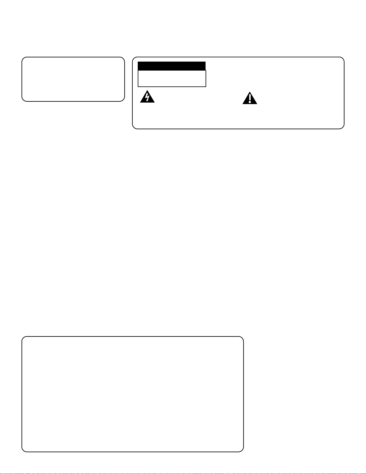
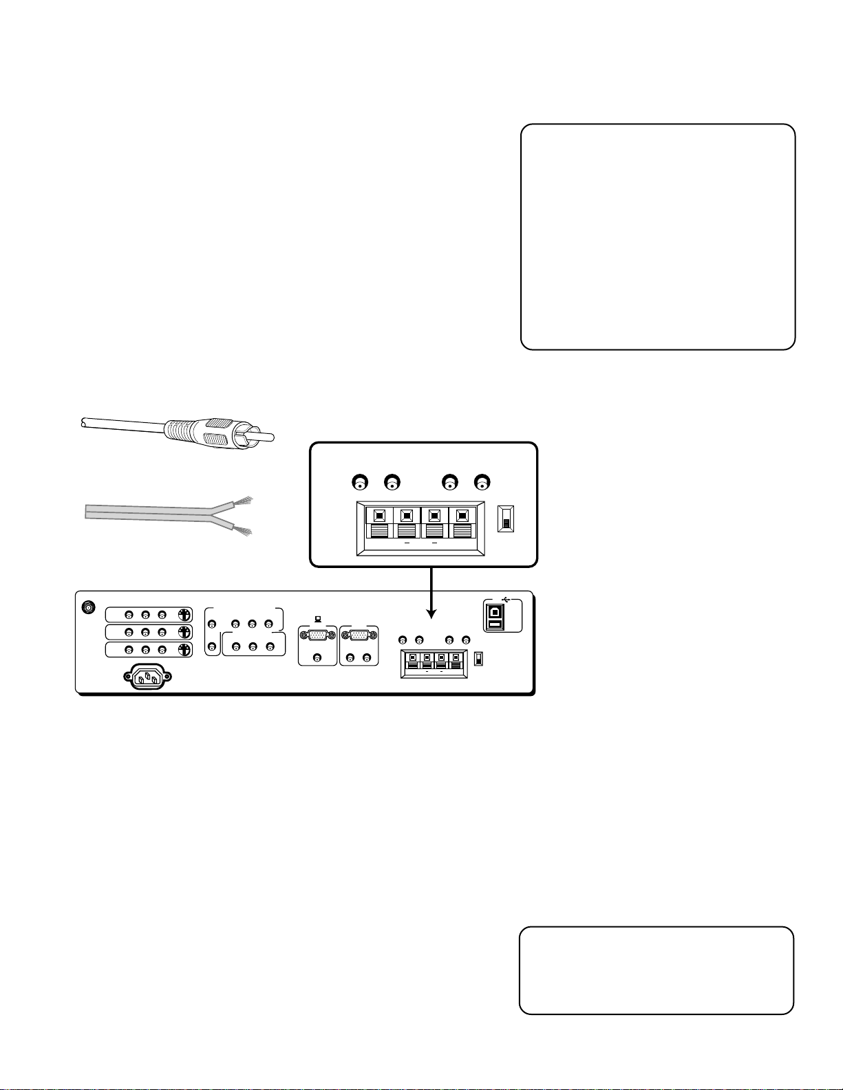
ANTENNA/CABLE IN
The ANTENNA/CABLE IN jack lets you connect a screw-on or push on
antenna or cable lead. Use this if you want the monitor to receive signals
through a coaxial cable from an antenna or other source, such as a VCR.
ANTENNA/
CABLE INPUT
Push-on coaxial cable
S-VIDEO
COMPONENT VIDEO INPUT
AUDIO
R
L
YP
SELECTED OUTPUTS
VIDEO
BPR
AUDIO
L
(S)VGA 1
R
STEREO INPUT
ANTENNA/
CABLE INPUT
INPUT1
INPUT2
INPUT3
POWER
AUDIO
VIDEO
L
R
You can use coaxial cables to connect devices such as:
• Antenna or cable leads
• Cable boxes
Screw-on coaxial cable
DIGITAL TV
INPUT
(S)VGA 2
AUDIO INPUTS
L
R
AUDIO OUTPUTS
FIXED
LR L
EXT SPEAKERS
R
VARIABLE
L
USB
PC/
HUB
DEVICE/
HUB
R
EXT
INT
++
• VCRs
• Satellite receivers
6
Page 9
Connections & Setup
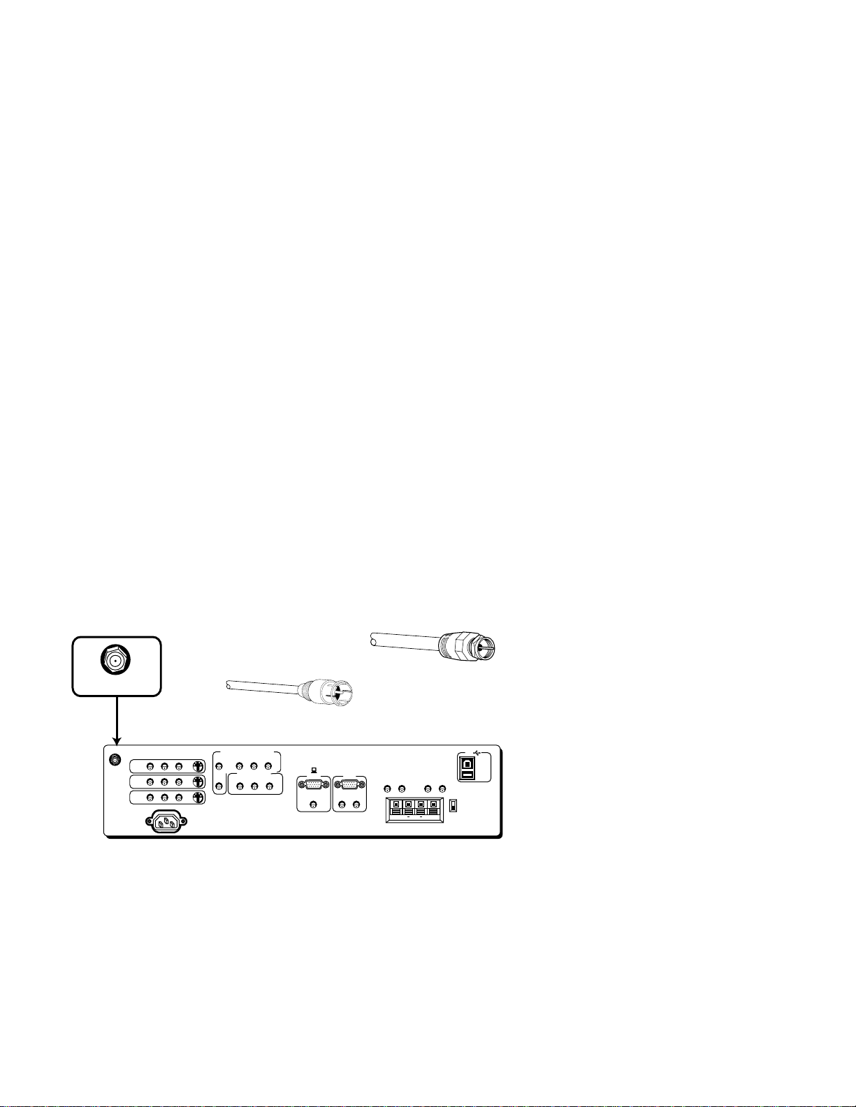
AUDIO/VIDEO/S-VIDEO INPUTS (INPUT1, INPUT2, INPUT3)
The audio jacks provide stereo sound. If your device has only one audio
output, you need to connect a “Y” adapter to your component and to both
the left and right inputs on the monitor.
The video jack provides better picture quality than coaxial cable, because
it carries only video signals.
If your device has S-Video output, use an S-Video cable to connect the
video jacks. This method separates the video signals into two separate
signals: one for color, the other for brightness. This helps prevent the signal
from degrading and results in a sharper image.
POWER
AUDIO
L
R
S-VIDEO
RCA cable
S-Video cable
(ENLARGED VIEW)
AUDIO
VIDEO
L
R
S-VIDEO
COMPONENT VIDEO INPUT
AUDIO
BPR
YP
R
L
SELECTED OUTPUTS
VIDEO
AUDIO
R
L
(S)VGA 1
STEREO INPUT
DIGITAL TV
INPUT
(S)VGA 2
AUDIO INPUTS
L
R
AUDIO OUTPUTS
FIXED
LR L
EXT SPEAKERS
L
R
VARIABLE
++
R
USB
PC/
HUB
DEVICE/
HUB
EXT
INT
INPUT1
INPUT2
INPUT3
ANTENNA/
CABLE INPUT
VIDEO
INPUT1
INPUT2
INPUT 3
You can use Audio/Video and S-Video jacks to connect devices such as:
• VCRs
• Satellite receivers
• DVD players
• Laserdisc players
Remember that if you are using S-Video
cables, you must also use RCA cables.
• Camcorders
• Internet devices
To View the Video Inputs...
First, press the TV button on the remote to
make sure that the remote is in TV mode;
then press the INPUT button to scroll
through the video inputs.
7
Page 10
Connections & Setup
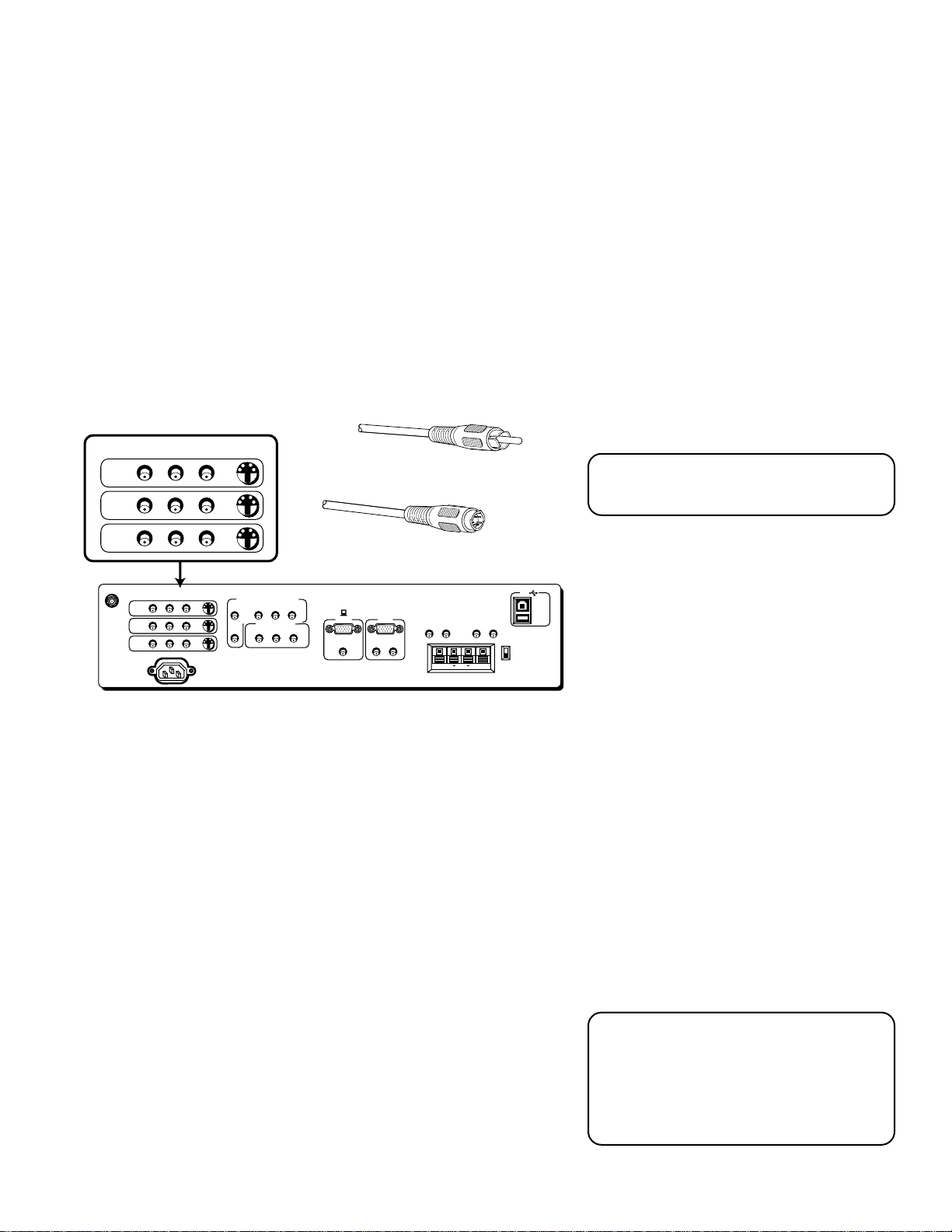
SELECTED AUDIO/VIDEO OUTPUTS
Provides audio and video output from your last selected source (except
component and SVGA jacks).
VIDEO provides video output. It gives better picture quality than just a
coaxial cable because it carries only video signals.
AUDIO L and R provide stereo sound. It gives better audio quality than
just an RF coaxial cable because it carries only audio signals.
SELECTED OUTPUTS
VIDEO
AUDIO
VIDEO
L
R
S-VIDEO
ANTENNA/
CABLE INPUT
INPUT1
INPUT2
INPUT3
POWER
AUDIO
R
L
You can use Audio/Video jacks to connect devices such as:
L
COMPONENT VIDEO INPUT
YP
SELECTED OUTPUTS
VIDEO
BPR
AUDIO
L
AUDIO
R
R
(ENLARGED VIEW)
(S)VGA 1
STEREO INPUT
DIGITAL TV
INPUT
(S)VGA 2
AUDIO INPUTS
L
R
Audio/Video cable
AUDIO OUTPUTS
FIXED
VARIABLE
LR L
EXT SPEAKERS
R
R
++
L
USB
PC/
HUB
DEVICE/
HUB
EXT
INT
In PC Mode...
In PC mode, the last selected source (for
the selected output) appears. The source
is what you were watching on INPUT 1,
2, 3, FRONT, or the tuner channel.
• compatible A/V receivers
• compatible recording equipment
• PCs with a compatible graphics card
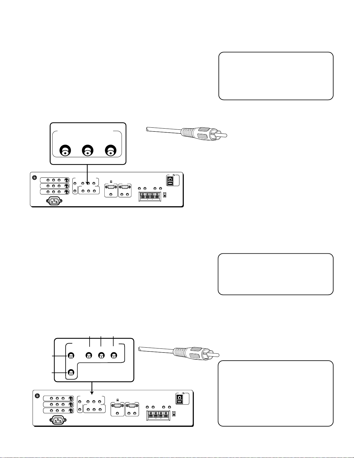
AUDIO/COMPONENT VIDEO INPUTS
These jacks let you connect a compatible component video source,
such as a DVD player or digital TV converter box. Unlike a single
video input, component video maintains the video signal as three
separate signals. The component video connection provides optimum
quality. The audio jacks provide stereo sound. It is essential to match
the color coded connectors between a compatible device and the
monitor.
Red
White
VIDEO
INPUT1
ANTENNA/
CABLE INPUT
INPUT2
INPUT3
POWER
AUDIO
L
R
Green Blue
COMPONENT VIDEO INPUT
AUDIO
R
L
S-VIDEO
COMPONENT VIDEO INPUT
AUDIO
R
L
VIDEO
YP
YP
SELECTED OUTPUTS
BPR
AUDIO
L
B
R
Red
P
R
(ENLARGED VIEW)
(S)VGA 1
STEREO INPUT
DIGITAL TV
INPUT
(S)VGA 2
AUDIO INPUTS
L
R
AUDIO OUTPUTS
FIXED
VARIABLE
LR L
EXT SPEAKERS
L
R
RCA cable
USB
R
EXT
INT
++
PC/
HUB
DEVICE/
HUB
Component Video Tip
To ensure maximum picture quality, use
three video-grade cables for the Y, PB, and
PR connections.
To View the Component Video
Input...
First, press the TV button on the remote to
make sure that the remote is in TV mode;
then press the INPUT button to scroll
through the video inputs until you get to
the COMP input.
8
Page 11
Connections & Setup
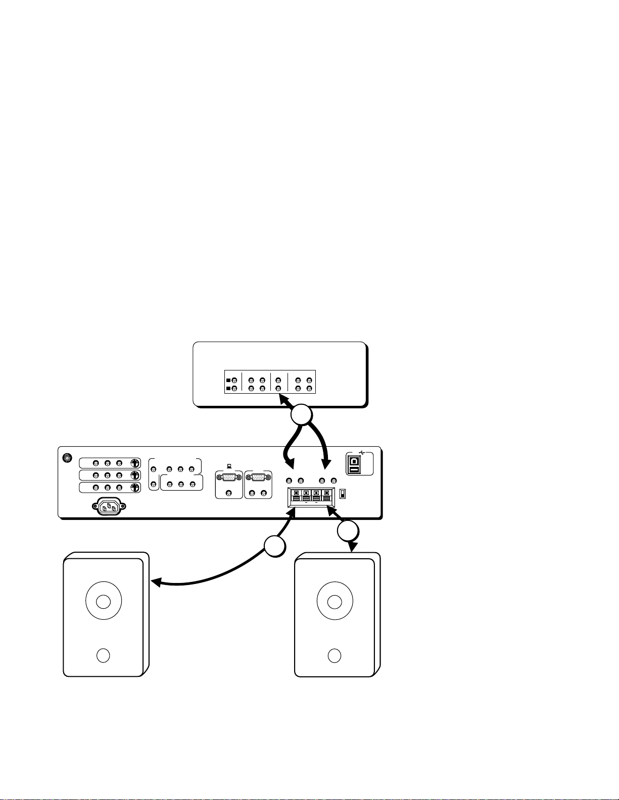
AUDIO OUTPUT
FIXED provides fixed-level audio output from the monitor. This audio
output is ideal for connecting to an A/V receiver when you want to
control the volume through the A/V receiver.
VARIABLE provides variable-level audio output. Volume levels are
controlled by the volume controls on the monitor and monitor remote
control.
EXT SPEAKERS lets you connect external left and right speakers to the
monitor. The EXT/INT switch beside the jacks let you turn the monitor’s
internal speakers on or off. EXT sends audio to external speakers. INT
sends audio only to the monitor’s internal speakers.
RCA cable
AUDIO OUTPUTS
FIXED
LR L
EXT SPEAKERS
VARIABLE
R
Audio Output Tips
• You may want to adjust the monitor’s
tone control and audio processor
settings to enhance the audio output
when connecting an A/V receiver to the
Variable output jacks.
• You can turn off the monitor’s internal
speakers by using the “Speakers”
control in the Audio menu. (See the
“Audio Menu” section for more
information.)
EXT
Speaker wire
R
AUDIO
VIDEO
L
R
S-VIDEO
COMPONENT VIDEO INPUT
ANTENNA/
CABLE INPUT
INPUT 1
INPUT 2
INPUT 3
POWER
AUDIO
R
L
YP
SELECTED OUTPUTS
VIDEO
BPR
AUDIO
L
DIGITAL TV
INPUT
(S)VGA 1
R
STEREO INPUT
(S)VGA 2
AUDIO INPUTS
L
R
FIXED
LR L
You can use audio output jacks to connect devices such an:
• Audio/Video receiver
• Audio amplifier
• Optional external speakers
AUDIO OUTPUTS
EXT SPEAKERS
R
L
VARIABLE
L
++
R
++
INT
(ENLARGED VIEW)
USB
PC/
HUB
DEVICE/
HUB
EXT
INT
External Speaker Rating
The external speaker rating is 8 ohms with
10 watts power handling capabilities.
9
Page 12
Connections & Setup
OPTIONAL COMPONENT CONNECTION EXAMPLES
The following examples feature some of the optional components you
can connect to your monitor. Refer to the preceding pages for the types
of cables used for each connection.
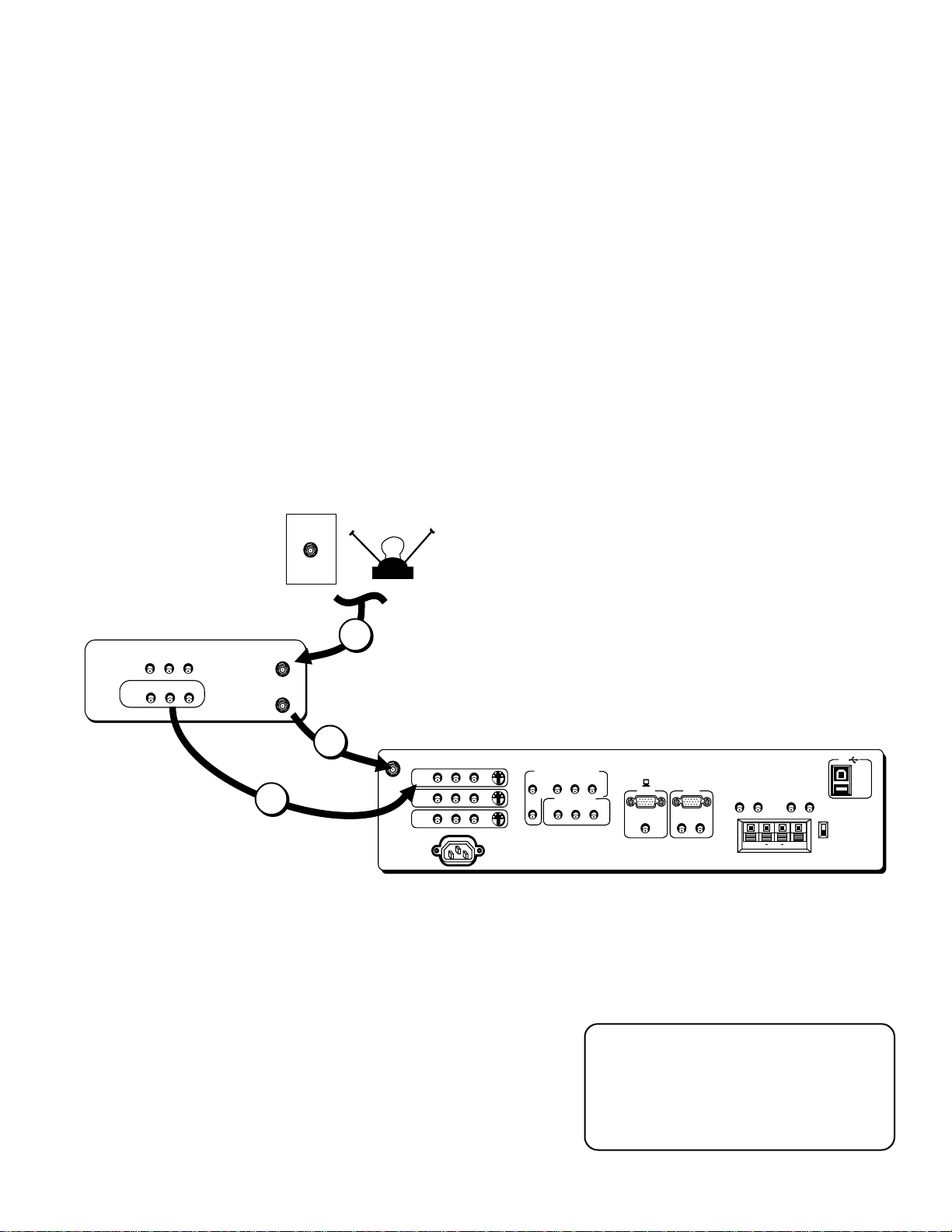
Monitor and a VCR
1. Connect the coaxial cable carrying your television signal (off air or
cable) to the antenna input on the VCR.
2. Connect a coaxial cable to the VCR’s antenna output and to the
ANTENNA/CABLE INPUT jack on the monitor.
3. Use RCA cables to connect the VCR’s Audio/Video output to
INPUT1 on the monitor.
VCR
CABLE
AUDIO
VIDEO
L
IN
OUT
R
AUDIO
VIDEO
L
R
ANTENNA IN
ANTENNA OUT
OFF-AIR ANTENNA
1
2
CABLE INPUT
3
Viewing the VCR Input Channel
1. Turn on the monitor and the VCR.
2. Press the TV button on the remote control.
ANTENNA/
INPUT1
INPUT2
INPUT3
POWER
VIDEO
AUDIO
L
R
S-VIDEO
COMPONENT VIDEO INPUT
AUDIO
R
L
VIDEO
BPR
YP
SELECTED OUTPUTS
AUDIO
L
DIGITAL TV
INPUT
(S)VGA 1
R
STEREO INPUT
(S)VGA 2
AUDIO INPUTS
L
R
AUDIO OUTPUTS
FIXED
LR L
EXT SPEAKERS
R
VARIABLE
L
USB
PC/
HUB
DEVICE/
HUB
R
EXT
INT
++
3. Press INPUT on the remote to scroll through the video inputs.
10
Direct Channel Tuning
You can set up the monitor to
automatically tune to the VCR input. This
is called auto tuning. (See “Setup” for
more information.)
Page 13
Connections & Setup
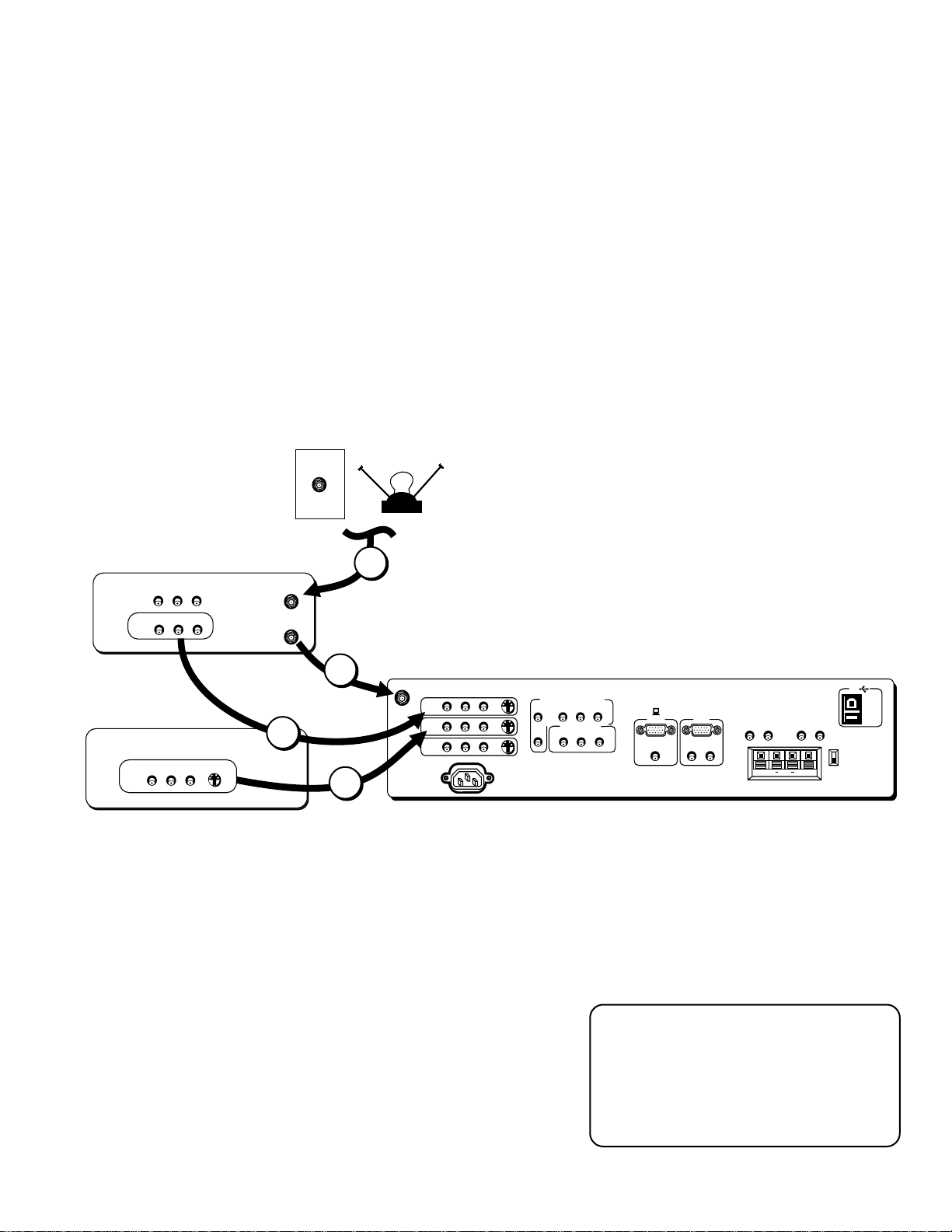
Monitor, VCR, and a Satellite Receiver
1. Connect the coaxial cable carrying your television signal (off air or
cable) to the antenna input on the VCR.
2. Connect a coaxial cable to the VCR’s antenna output and to the
ANTENNA/CABLE INPUT jack on the monitor.
3. Use RCA cables to connect the VCR’s Audio/Video output INPUT1
on the monitor.
4. Use RCA cables to connect the satellite receiver’s audio/video
output to INPUT2 on the monitor. If your satellite receiver has an
S-Video output, you can make the video connection by using the
S-Video jacks instead.
CABLE
OFF-AIR ANTENNA
1
VCR
AUDIO
VIDEO
L
IN
OUT
R
AUDIO
VIDEO
L
R
ANTENNA IN
ANTENNA OUT
2
AUDIO
VIDEO
L
R
INPUT1
ANTENNA/
CABLE INPUT
SATELLITE
RECEIVER
3
S-VIDEO
AUDIO
VIDEO
L
OUT
R
4
INPUT2
INPUT3
POWER
Viewing the Components
1. Turn on the monitor and the component(s) you want to view.
2. Press the TV button on the remote control.
S-VIDEO
COMPONENT VIDEO INPUT
AUDIO
R
L
VIDEO
BPR
YP
SELECTED OUTPUTS
AUDIO
L
USB
PC/
R
HUB
DEVICE/
HUB
EXT
INT
DIGITAL TV
INPUT
(S)VGA 1
R
STEREO INPUT
(S)VGA 2
AUDIO INPUTS
L
R
AUDIO OUTPUTS
FIXED
LR L
EXT SPEAKERS
R
VARIABLE
L
++
3. Press the INPUT button on the remote control to scroll through the
video inputs.
• The VCR can be viewed on the VID 1 input channel.
• The satellite receiver can be viewed on the VID 2 input
channel.
Direct Channel Tuning
You can set up the monitor to
automatically tune to the correct input
for channel. This is called auto tuning.
(See “Setup” for more information.)
11
Page 14
Connections & Setup
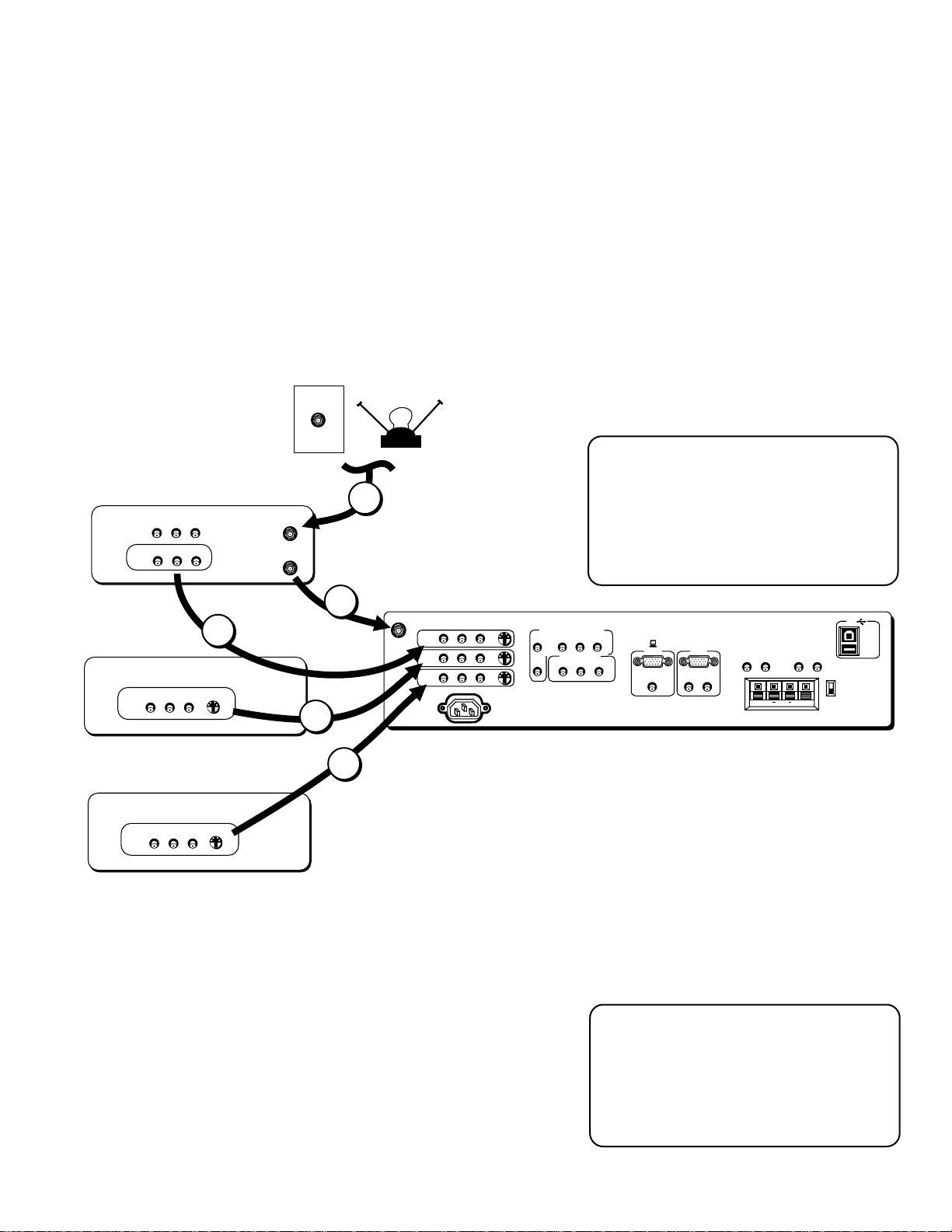
Monitor, VCR, Satellite Receiver, and a DVD Player
1. Connect the coaxial cable carrying your television signal (off air or cable) to the antenna input on the VCR.
2. Connect a coaxial cable to the VCR’s antenna output and to the ANTENNA/CABLE INPUT jack on the monitor.
3. Use RCA cables to connect the VCR’s Audio/Video output to INPUT1 on the monitor.
4. Use RCA cables to connect the satellite receiver’s Audio/Video output to INPUT2 on the monitor. If your satellite
receiver has an S-Video output, you can make the video connection by using the S-Video jacks instead.
5. Use RCA cables to connect the DVD player’s Audio/Video output to INPUT3 on the monitor. If your DVD player has
an S-Video output, you can make the video connection by using the S-Video jacks instead.
VCR
SATELLITE
RECEIVER
DVD PLAYER
CABLE
AUDIO
VIDEO
L
IN
OUT
R
AUDIO
VIDEO
L
R
ANTENNA IN
ANTENNA OUT
OFF-AIR ANTENNA
1
Component Video
If your DVD player has a component
video output, we recommend you use the
component video input on the monitor
instead of the standard video or s-video
connection.
2
AUDIO
VIDEO
L
R
3
S-VIDEO
AUDIO
VIDEO
L
OUT
R
ANTENNA/
CABLE INPUT
INPUT1
INPUT2
INPUT3
POWER
S-VIDEO
4
COMPONENT VIDEO INPUT
AUDIO
R
L
YP
SELECTED OUTPUTS
VIDEO
BPR
AUDIO
L
DIGITAL TV
INPUT
(S)VGA 1
R
STEREO INPUT
(S)VGA 2
AUDIO INPUTS
L
R
AUDIO OUTPUTS
FIXED
LR L
EXT SPEAKERS
R
VARIABLE
L
USB
PC/
HUB
DEVICE/
HUB
R
EXT
INT
++
5
S-VIDEO
AUDIO
VIDEO
L
R
Viewing the Components
1. Turn on the monitor and the component(s) you want to view.
2. Press the TV button on the remote control.
3. Press the INPUT button on the remote control to scroll through the
video inputs.
• The VCR can be viewed on the VID 1 input channel.
• The satellite receiver can be viewed on the VID 2 input
channel.
• The DVD player can be viewed on the VID 3 input channel.
12
Direct Channel Tuning
You can set up the monitor to
automatically tune to the correct input
for channel. This is called auto tuning.
(See “Setup” for more information.)
Page 15
Connections & Setup
A/V Receiver & Speakers
1. Use RCA cables to connect either the FIXED or VARIABLE A UDIO
OUTPUT from the monitor to an A/V receiver.
• FIXED provides fixed-level audio output from the monitor.
This audio output is ideal for connecting to an A/V receiver
that has its own volume control.
• VARIABLE provides variable-level audio output. Volume
levels are controlled by the volume controls on the monitor
and monitor remote control.
2. Use speaker wire to connect the monitor to external speakers.
• The EXT/INT switch beside the jacks let you turn the monitor’s
internal speakers on or off. EXT sends audio to external and
internal speakers. INT sends audio only to the monitor’s
internal speakers.
ANTENNA/
CABLE INPUT
INPUT 1
INPUT 2
INPUT 3
POWER
A/V RECEIVER
TAPE
CD
IN
L
R
TV
IN OUT IN
IN
VCR
OUT
1
Connect to either FIXED or VARIABLE Output
AUDIO
VIDEO
L
R
S-VIDEO
COMPONENT VIDEO INPUT
AUDIO
R
L
YP
SELECTED OUTPUTS
VIDEO
BPR
AUDIO
L
DIGITAL TV
INPUT
(S)VGA 1
R
STEREO INPUT
(S)VGA 2
AUDIO INPUTS
L
R
AUDIO OUTPUTS
FIXED
LR L
EXT SPEAKERS
R
VARIABLE
L
USB
PC/
HUB
DEVICE/
HUB
R
EXT
INT
++
2
2
Right Speaker
Left Speaker
13
Page 16
Connections & Setup
PICTURE MODE
1 Computer/Text
2 Video
TV
ON OFF
AUX
DVD
FETCH
GO BACK
SKIPMUTE
INFO
MENU
OK
CLEAR
GUIDE
VCR1
VCR2
DIRECTV
C
H
+
C
H
-
V
O
L
V
O
L
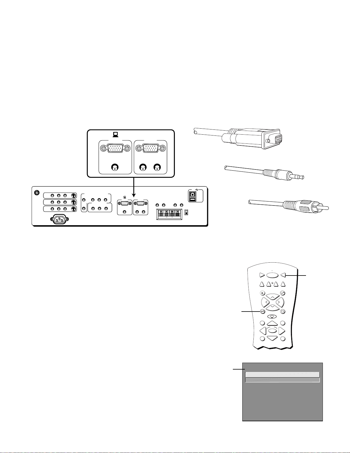
(S)VGA VIDEO INPUTS –(S)VGA1, (S)VGA2
The (S)VGA (Super Video Graphics Adapter) inputs let you connect
your monitor to a personal computer and internet devices. These inputs
can provide up to 800 pixel x 600 pixel resolution. How images are
displayed, however, depends on other factors such as the type of
device connected to the monitor, the media being transmitted,
graphics cards and memory allotments.
DIGITAL TV
(S)VGA 1
INPUT
(S)VGA 2
AUDIO INPUTS
L
DIGITAL TV
INPUT
(S)VGA 2
AUDIO INPUTS
L
R
R
(ENLARGED VIEW)
AUDIO OUTPUTS
FIXED
LR L
EXT SPEAKERS
R
VARIABLE
L
USB
PC/
HUB
DEVICE/
HUB
R
EXT
INT
++
ANTENNA/
CABLE INPUT
INPUT1
INPUT2
INPUT3
POWER
STEREO INPUT
AUDIO
VIDEO
L
R
S-VIDEO
COMPONENT VIDEO INPUT
AUDIO
R
L
YP
SELECTED OUTPUTS
VIDEO
BPR
AUDIO
L
(S)VGA 1
R
STEREO INPUT
Scan Rates
The computer scan rates supported are:
• VGA 640x480, 60Hz progressive
for Projection—screens over 36”
640x480, 60/72Hz progressive
for Direct View—screens 5-36”
• (S)VGA 800x600, 60Hz progressive
• XGA 1024x768, 43Hz interlaced (available only for
Direct View—screens 5-36”)
Make sure that you appropriately adjust the display properties for your
computer.
(S)VGA cable
Stereo mini-jack cable
RCA cable
TV button
Fetch button
You can change the picture mode settings for the (S)VGA inputs by
using the Picture Mode menu. To access the Picture Mode menu, press
the TV button and then the FETCH button on the remote.
14
Computer/Text is the default setting for the (S)VGA 1 input. This
input and setting is recommended for most PC connections when
viewing text and graphics. Text may appear crisper in Text mode.
Video is the default setting for the (S)VGA 2 input. This input and
setting is recommended for high definition television (HDTV)
converter connections. Also, computer games may appear better in
Video mode. The appearance of text in Video mode may be
improved by turning down the picture’s sharpness and contrast
(see the section “Menus and Features” for details).
Picture
Mode
menu
Page 17
Connections & Setup
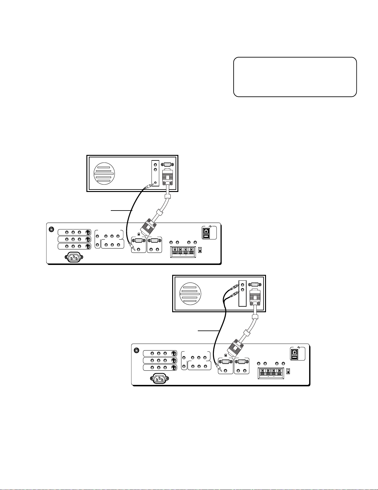
(S)VGA 1 Input Connection Examples
1. Connect the supplied (S)VGA cable to your computer and to the
monitor.
2. Connect the audio:
• Connect the stereo mini-jack cable to the computer and to the
STEREO INPUT jack on the monitor.
OR
• Connect the RCA-type connectors of a “Y” adapter to the
audio outputs on the computer, and connect the stereo minijack connector to the STEREO INPUT jack on the monitor.
BACK OF COMPUTER
The (S)VGA 1 input supports DDC2B and
VESA DPMS when using an appropriate
cable. We recommend using the VGA
cable supplied with this monitor.
Stereo mini-jack cable
VIDEO
INPUT1
ANTENNA/
CABLE INPUT
INPUT2
INPUT3
POWER
AUDIO
L
R
S-VIDEO
COMPONENT VIDEO INPUT
AUDIO
BPR
YP
R
SELECTED OUTPUTS
AUDIO
L
R
L
VIDEO
(S)VGA 1
STEREO INPUT
DIGITAL TV
INPUT
(S)VGA 2
AUDIO INPUTS
L
R
AUDIO OUTPUTS
FIXED
LR L
EXT SPEAKERS
R
VARIABLE
L
USB
PC/
HUB
DEVICE/
HUB
R
EXT
INT
++
BACK OF COMPUTER
“Y” Adapter
ANTENNA/
CABLE INPUT
INPUT1
INPUT2
INPUT3
POWER
AUDIO
VIDEO
L
R
S-VIDEO
COMPONENT VIDEO INPUT
AUDIO
BPR
YP
R
SELECTED OUTPUTS
AUDIO
L
R
L
VIDEO
(S)VGA 1
STEREO INPUT
DIGITAL TV
INPUT
(S)VGA 2
AUDIO INPUTS
L
R
AUDIO OUTPUTS
FIXED
LR L
EXT SPEAKERS
R
VARIABLE
L
USB
PC/
HUB
DEVICE/
HUB
R
EXT
INT
++
Viewing the (S)VGA 1 Input
1. Turn on the monitor and the computer.
2. Press the TV button on the remote control.
3. Press the INPUT button on the remote control to scroll through the video inputs until
you get to the VGA 1 input.
(If you have difficulty getting your screen to appear on the monitor, see the Troubleshooting
section of this manual for possible solutions.)
15
Page 18
Connections & Setup
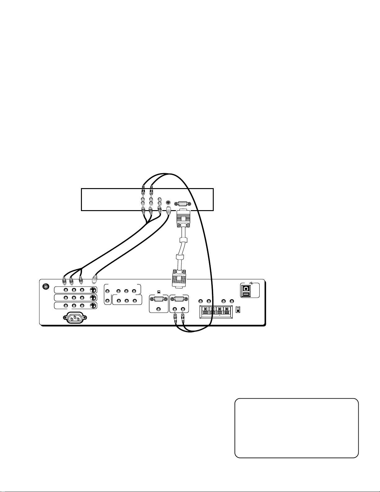
(S)VGA 2 Input
The (S)VGA 2 input can be used to connect an HD receiver so you can receive high
definition signals.
1. Connect the supplied (S)VGA cable to your HD receiver and to the monitor. Due to
copyright restrictions, you may not be able to view some high definition programs in high
definition format using this product. To view material in standard definition instead, you
must connect the Audio/Video jacks to the monitor.
2. Connect an RCA-type cable from the HD receiver’s AUDIO Right, Left, and VIDEO jacks to
the AUDIO IN Right, Left, and VIDEO jacks on the monitor.
3. Connect an Audio cable from the HD receiver’s AUDIO Right and Left jacks to the
monitor’s VGA Left and Right Audio inputs.
4. Connect an optional S-Video cable from the HD receiver’s S-VIDEO jack to the monitor’s SVIDEO jack.
HD RECEIVER
RRL
AUDIO
L
-OR-
ANTENNA/
CABLE INPUT
INPUT 1
INPUT 2
INPUT 3
POWER
AUDIO
VIDEO
L
R
S-VIDEO
COMPONENT VIDEO INPUT
AUDIO
R
L
YP
SELECTED OUTPUTS
VIDEO
BPR
AUDIO
L
R
Viewing the (S)VGA 2 Input
1. Turn on the monitor and the HD receiver.
2. Press the TV button on the remote control.
VIDEO
(S)VGA 1
STEREO INPUT
DIGITAL TV
INPUT
(S)VGA 2
AUDIO INPUTS
L
R
AUDIO OUTPUTS
FIXED
LR L
EXT SPEAKERS
R
VARIABLE
L
USB
PC/
HUB
DEVICE/
R
++
HUB
EXT
INT
3. Press the INPUT button on the remote control to scroll through the
video inputs until you get to the VGA 2 input.
If your RCA or PROSCAN HD receiver switches from a high definition
output to a standard definition output, the monitor will automatically
switch from the high definition (S)VGA2 input channel to the standard
definition INPUT2 (VID2) channel in order for you to view the signal.
There are two situations in which this would occur:
• When recording from the HD receiver;
• When a high definition output signal is not allowed by the program
provider and/or movie studio for that particular program.
16
Direct Channel Tuning
You can set up the monitor to
automatically tune to the (S)VGA 2 input
when you press the DIRECTV button on
the remote. This is called auto tuning.
(See “Setup” for more information.)
Page 19
Connections & Setup
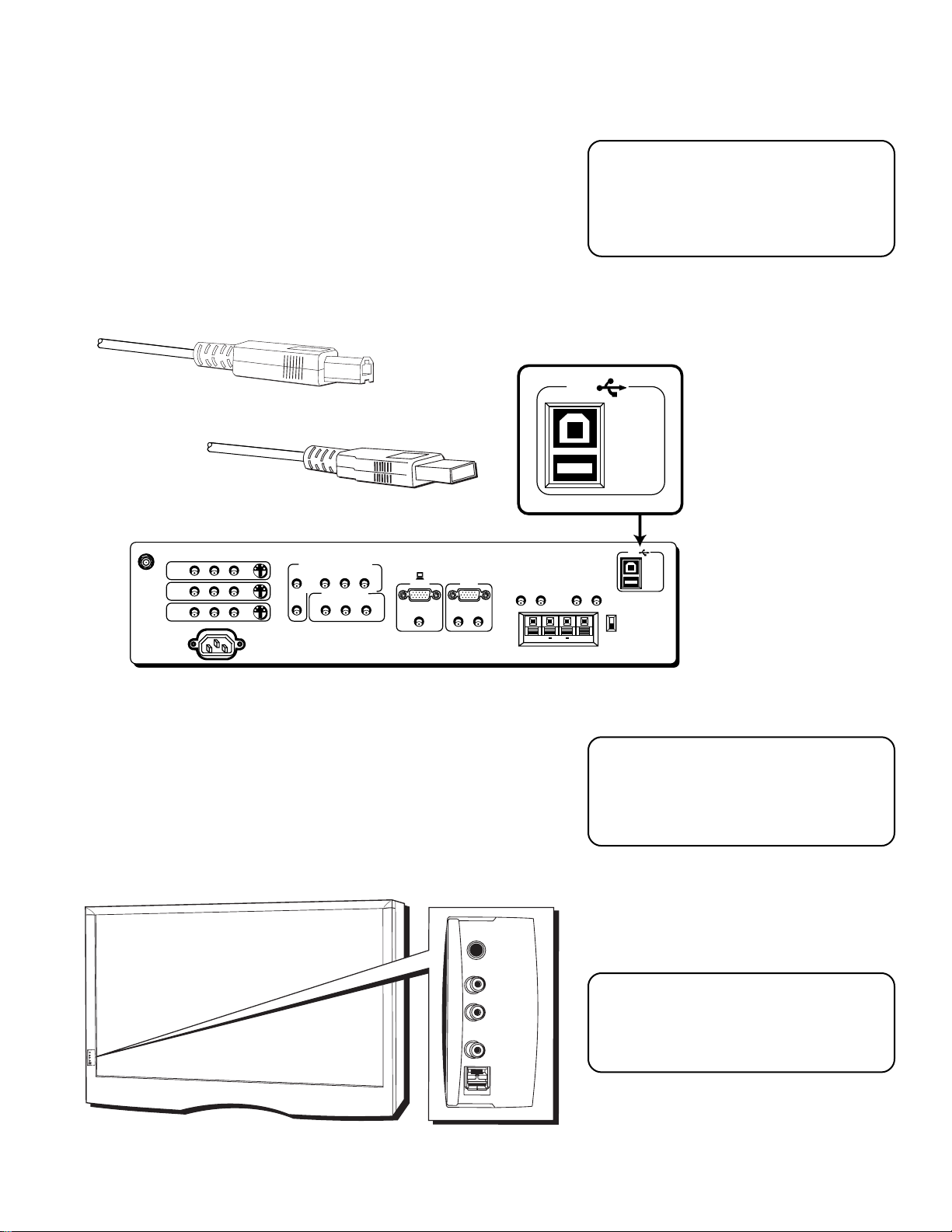
USB INPUTS/OUTPUT
USB (Universal Serial Bus) inputs let you connect PC-type peripheral
devices to the monitor. This includes devices such as joysticks,
keyboards, and pointing devices (mouse, trackball). There are three
USB inputs and one USB output that connects to a PC. The monitor
acts as a hub to the PC.
NOTE
The USB port will function even when
the monitor is in standby mode (off but
plugged in).
USB cable (type A)
USB cable (type B)
AUDIO
VIDEO
L
R
ANTENNA/
CABLE INPUT
INPUT1
S-VIDEO
INPUT2
INPUT3
POWER
COMPONENT VIDEO INPUT
AUDIO
R
L
YP
SELECTED OUTPUTS
L
VIDEO
BPR
AUDIO
R
(S)VGA 1
STEREO INPUT
DIGITAL TV
INPUT
(S)VGA 2
AUDIO INPUTS
L
R
FIXED
LR L
FRONT INPUTS
The monitor has front inputs for convenience; one set of audio/video
inputs, a headphone jack and two client USB ports. Look for a hinged
door and gently lift the cover open. Please note that the TV below
shows a typical front input layout on a Direct View TV. The exact look
of the jacks or the TV pictured here may be different from yours.
USB
(ENLARGED VIEW)
AUDIO OUTPUTS
VARIABLE
EXT SPEAKERS
++
L
R
PC/
HUB
DEVICE/
HUB
USB
PC/
HUB
DEVICE/
R
HUB
EXT
INT
NOTE
When you plug in headphones, the
monitor’s internal and external speakers
are turned off.
PHONES
VIDEO IN
When connecting devices that use a
L (MONO)
AUDIO IN
PHONES
VIDEO IN
L (MONO)
AUDIO IN
R
USB
USB
monaural cable, such as some
camcorders, use the left input jack to get
sound from both speakers.
17
Page 20
Connections & Setup
TV
ON OFF
AUX
DVD
FETCH
GO BACK
SKIPMUTE
INFO
MENU
OK
CLEAR
GUIDE
VCR1
VCR2
DIRECTV
C
H
+
C
H
-
V
O
L
V
O
L
SETTING UP THE MONITOR
Follow these steps when setting up the monitor for the first time.
STEP 1: PLUG IN THE MONITOR
Plug the end of the power cord into an appropriate wall outlet. Be sure
to insert the plug completely.
STEP 2: PLACE BATTERIES IN REMOTE
• Remove the battery compartment cover from the back of the
remote by pushing down on and sliding off the cover.
• Insert fresh batteries. Make sure that the polarities (+ and -) are
aligned correctly.
• Replace the cover.
STEP 3: TURN ON THE MONITOR
Press TV on the remote, or press POWER on the monitor’s front panel.
Pressing the TV button not only turns on the monitor, but puts the
remote into TV mode, so that the buttons on the remote will control
monitor functions.
STEP 4: SET UP THE MONITOR
The information that follows gives you step by step instructions for the
first time set up of your monitor. Take time now to read the next
section, “Setting Up Your Monitor,” and complete the set up routine.
FIRST-TIME SETUP
The first-time setup of your monitor includes: setting the time, auto
channel search, setting up the auto tuning feature, and labeling the
channels and inputs. Refer to this section if you ever need to reset any
of these initial settings.
TV
button
18
Page 21

Connections & Setup
MENU
OK
CLEAR
THE POINT AND SELECT NAVIGATION METHOD
You can “get around” in the menu system by using just a few buttons
on the remote control. We call this the “Point and Select” method of
navigation, and it has two steps.
1. Point to a menu item using the arrows on the remote.
To point up or down, press the up or down arrows. To point left or
right, press the left or right arrows.
2. Select a menu item by pressing MENU or OK.
Selecting an item tells the monitor’s menu system to go ahead and
make the change or go to a place you have indicated.
Point and Select
buttons
SET THE TIME
The first step in the setup is to set the time.
1. Press MENU on the remote control to bring up the Main menu.
MAIN MENU
1 Audio
2 Picture Quality
3 Screen
4 Channel
5 Time
6 Parental Controls
0 Go Back
2. Point to T ime, and press OK to select it.
SET TIME
: AM
Enter
01 to 12
Press OK to exit.
for the hour.
Alternate Navigation Method
In addition to using Point & Select, you
can also select a menu item by entering
the item number with the number
buttons on the remote.
Press CLEAR at any time to remove all
displays from the screen and return to
normal viewing.
Many VCR user manuals refer to a
PROGRAM button. The MENU button on
this remote works as a PROGRAM button
in VCR mode. Other manuals may refer
to a SELECT button. The OK button on
this remote works as a SELECT button.
3. Use the left and right arrows to point to the hour and minutes
spaces. Use the up and down arrows to scroll through the numbers
(or use the digit keys on the remote) and change from AM to PM.
Press OK to exit.
19
Page 22

Connections & Setup
AUTO CHANNEL SEARCH
The next step of the setup routine “autoprograms” channels into the
channel list.
1. Press MENU bring up the Main menu and then select Channel.
MAIN MENU
1 Audio
2 Picture Quality
3 Screen
4 Channel
5 Time
6 Parental Controls
0 Go Back
2. From the Channel menu (shown below), select Auto Channel
Search.
CHANNEL
1 Signal Type
Auto Channel Search
2
3 List and Labels
4 Autotuning
0 Exit
The monitor will begin searching for channels and give you a
progress report. When the channel search is complete, press OK on
the remote to go back to the Channel menu.
20
Page 23

Connections & Setup
SET THE VCR1 CHANNEL (AUTOTUNING)
The next step lets you set the VCR1 channel. When you set the VCR1
channel, the monitor automatically tunes to the correct input channel
when press the VCR1 button on the remote. This is called “Autotuning.”
If you don’t have a VCR1 component connected to the monitor, skip
this step.
1. From the Channel menu (shown below), select Autotuning.
CHANNEL
1 Signal Type
Auto Channel Search
2
3 List and Labels
4 Autotuning
0 Go Back
2. From the Autotuning menu (shown below), select Set V CR1
Channel.
AUTOTUNING
1 Set VCR1 Channel...
2 Set VCR2 Channel...
3 Set DVD Channel...
4 Set SAT/CABLE Channel...
0 Go Back
3. From the Set VCR1 Channel menu (shown below), point to the
choice that matches the way you have your VCR connected to the
monitor.
SET VCR1 CHANNEL
1 Not connected
2 Channel 3
3 Channel 4
4 Video 1 Input
5 Video 2 Input
6 Video 3 Input
4. Press OK to select it.
21
Page 24

Connections & Setup
SET THE VCR2 CHANNEL (AUTOTUNING)
You can set the VCR2 button on the remote to automatically tune to an
input channel as well. If you don’t have a VCR2 component connected
to the monitor, skip this step.
1. From the Channel menu (shown below), select Autotuning.
CHANNEL
1 Signal Type
Auto Channel Search
2
3 List and Labels
4 Autotuning
0 Go Back
2. From the A utotuning menu (shown below), select Set VCR2
Channel.
AUTOTUNING
1 Set VCR1 Channel...
2 Set VCR2 Channel...
3 Set DVD Channel...
4 Set SAT/CABLE Channel...
0 Go Back
3. From the Set VCR2 Channel menu (shown below), point to the
choice that matches the way you have your VCR connected to the
monitor.
SET VCR2 CHANNEL
1 Not connected
2 Channel 3
3 Channel 4
4 Video 1 Input
5 Video 2 Input
6 Video 3 Input
4. Press OK to select it.
22
Page 25

Connections & Setup
SET THE DVD CHANNEL (AUTOTUNING)
The next step lets you set the DVD channel. When you set the DVD
channel, you’re telling the monitor what channel to tune to when you
press the DVD button on the remote.
Indicate which input you used to connect an DVD player. If you don’t
have a DVD player connected to the monitor, skip this step.
1. From the Channel menu (shown below), select Autotuning.
CHANNEL
1 Signal Type
Auto Channel Search
2
3 List and Labels
4 Autotuning
0 Go Back
2. From the A utotuning menu (shown below), select Set DVD
Channel.
AUTOTUNING
1 Set VCR1 Channel...
2 Set VCR2 Channel...
3 Set DVD Channel...
4 Set SAT/CABLE Channel...
0 Go Back
3. From the Set DVD Channel menu (shown below), point to the
choice that matches the way you have your DVD connected to the
monitor.
SET DVD CHANNEL
1 Not connected
2 Channel 3
3 Channel 4
4 Video 1 Input
5 Video 2 Input
6 Video 3 Input
7 Component Input
4. Press OK to select it.
23
Page 26

Connections & Setup
SET THE SAT/CABLE CHANNEL (AUTOTUNING)
The next step lets you set the SAT/CABLE channel. When you set the
SAT/CABLE channel, you’re telling the monitor what channel to tune
to when you press the DIRECTV button on the remote.
Indicate which input you used to connect a satellite receiver, a cable
box or an HD receiver. If you don’t have one of these components
connected to the monitor, skip this step.
1. From the Channel menu (shown below), select Autotuning.
CHANNEL
1 Signal Type
Auto Channel Search
2
3 List and Labels
4 Autotuning
0 Go Back
2. From the Autotuning menu (shown below), select Set SAT/CABLE
Channel.
AUTOTUNING
1 Set VCR1 Channel...
2 Set VCR2 Channel...
3 Set DVD Channel...
4 Set SAT/CABLE Channel...
0 Go Back
3. From the Set SAT/CABLE Channel menu (shown below), point to
the choice that matches the way you have your satellite receiver,
cable box, or HD receiver connected to the monitor.
SET SAT/CABLE CHANNEL
1 Not connected
2 Channel 2
3 Channel 3
4 Channel 4
5 Video 1 Input
6 Video 2 Input
7 Video 3 Input
8 (S)VGA 2 Input
Note that the (S)VGA2 input can be used
to connect an HD receiver so you can
receive high definition signals.
4. Press OK to select it.
24
Page 27

Connections & Setup
LABEL THE CHANNELS
This last step in the setup routine lets you create your channel list and
label your channels.
1. From the Channel menu (shown below), select Lists and Labels.
CHANNEL
1 Signal Type
Auto Channel Search
2
3 List and Labels
4 Autotuning
0 Go Back
The Lists and Labels menu appears (shown below).
LIST AND LABELS
Channel Channel Channel
Number List Label
59 Yes FOX---
Use ^ or v, keypad, or CH ^/v
to set channel, MENU to exit.
Use the CH ^ (channel up) or CH v
(channel down) buttons to change
channels in the Channel Number field.
This works even if you’re not in the
Channel Number field. Or, enter the
channel number directly using the
number buttons on the universal remote.
To enter a number greater than 99, press
and hold “1” to enter the hundreds digit,
then press the two remaining numbers.
The list and labels feature can also be
accessed from the Channel menu.
Because this procedure can be time
consuming, feel free to skip this step and
come back to it later.
2. Use the left and right arrows to point to the three different areas of
the control panel (called “fields”).
3. Use the up and down arrows to scroll through the numbers (or use
the digit keys on the remote) and letters and select Yes or No in the
Channel List field. You may wish to refer to the call letters listed in
your newspaper’s TV section for ideas on labelling the channels.
4. Repeat this process for each of your channels. Then press MENU
or OK to continue. The monitor can store in memory as many
as 45 labels.
WHAT NOW?
Now that you’ve finished the setup, you can sit back, relax, and enjoy
the monitor, or you can take a few minutes to program the remote to
control your VCR, DVD player, satellite receiver, or other components.
To find out how to program the remote, go to the next section.
25
Page 28

Connections & Setup
26
Page 29

Using the Remote
HOW TO USE YOUR UNIVERSAL REMOTE
This section defines the buttons of the remote and
how to program it to control other components.
The universal remote can be programmed to
control most brands of remote controllable VCRs,
satellite receivers, and cable boxes. If you have an
RCA, GE, or PROSCAN component, you
probably don’t need to program it at all.
1
2
3
4
CONNECTIONS &
SETUP
USING THE REMOTE
➣
➣➣
MENUS AND FEATURES
REFERENCE
Modes of Operation
Because this universal remote can
control several different components
(DVD player, VCR, Cable Box, etc.) it
uses operational modes triggered by the
component buttons. For example if you
want the remote to control the TV, you
would press the TV button to put the
remote into TV mode before you could
control the TV.
27
Page 30

Using the Remote
REMOTE BUTTONS
ON•OFF When in TV mode, turns the monitor on and off. If in
another device mode (VCR, DVD, Satellite (DIRECTV), etc.) and
programmed, will turn the device on and off. Press twice within two
seconds to turn off most ProScan, RCA and GE products at once.
VCR1 Puts the remote in VCR mode and if auto tuning is enabled, it
will turn on the monitor and tune to the correct channel.
TV Turns on the monitor and puts the remote in TV mode. Also
displays channel information.
DVD Puts the remote in DVD mode and if auto tuning is enabled, it
will turn on the monitor and tune to the correct channel.
LED
VCR1
DVD
ON OFF
VCR2
H
C
L
O
V
C
H
+
AUX
-
TV
DIRECTV
SKIPMUTE
V
O
L
VCR2 Puts the remote in VCR2 mode and if auto tuning is enabled, it
will turn on the monitor and tune to the correct channel.
LED The LED light indicates programming mode when programming
the remote to control components.
AUX Puts the remote in AUX mode. Also, turns on the monitor.
DIRECTV Puts the remote in satellite mode and if auto tuning is
enabled, it will turn on the monitor and tune to the correct channel.
MUTE Reduces the monitor’s volume to its minimum level. Press
again to restore the volume.
SKIP Press once before changing channels and the monitor will wait
30 seconds before returning you to the original channel. Press
repeatedly to add more time.
CH ^ or CH v Scans up or down through the current channel list.
Press once to change the channel up or down; press and hold to
continue changing channels.
VOL – or VOL + Decreases or increases the monitor’s volume.
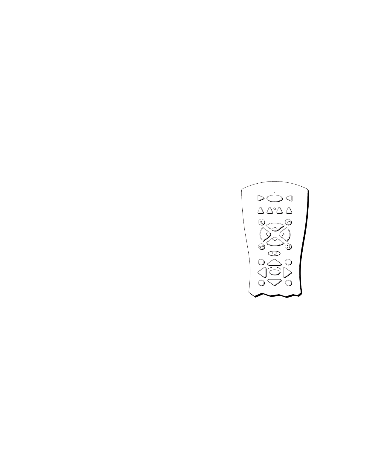
FETCH Brings up Picture Mode choice list (Computer/text or Video)
when tuned to VGA1 or VGA2. Some PROSCAN, RCA and GE
devices use FETCH as a shortcut to menu items.
1
4
7
FETCH
GUIDE
MENU
INPUT
RECORD
PIP
OK
2
5
8
0
PLAY FORWARDREVERSE
STOP PAUSE
SWAP
GO BACK
INFO
CLEAR
3
6
9
ANTENNA
WHOCH CTRL
Light Icon Press to illuminate the remote control’s buttons.
GO BACK Returns you to the previous channel or previous screen in
the menu system.
GUIDE In satellite (DIRECTV) mode, brings up available on-screen
guides.
INFO Brings up channel information; press again to clear the screen.
Move (Arrows) Used to point to different items in the menu system
and adjust the menu controls. Also moves the PIP window when no
menus are on the screen.
OK When in the menu system, selects highlighted items or returns
you to the previous menu.
28
NOTE
The VCR1, DVD, VCR2, and DIRECTV
buttons also turn on most RCA, GE and
PROSCAN products.
Page 31

Using the Remote
MENU Brings up the Main menu and selects highlighted items. When
in VCR mode, it functions as a PROGRAM button.
CLEAR Removes any menu or display from the screen and returns
you to normal viewing.
(0-9) Number Buttons Enters channel numbers and time settings
directly though the remote control. To enter a two-digit channel, press
the two digits. To enter a three-digit channel, press and hold the first
digit until the number and two dashes “– –” appear, then add the
second two. Example: to tune to channel 123, press and hold 1 until
“1– –” appears, release the 1 button and then press 2, and 3.
INPUT In TV mode, press to toggle through the available input
sources (VID1, VID2, VID3, FRONT, last channel, VGA1, VGA2,
component input).
ANTENNA Functions as TV/VCR button in VCR mode and TV/
receiver button in satellite (DIRECTV) mode.
REVERSE, PLAY, FORWARD, RECORD, STOP, PAUSE If programmed,
provides transport control for some remote-controllable VCRs, DVD
players, laserdisc players, tape decks, and CD players.
PIP Brings up the small picture-in-picture window. Press again to
remove the PIP window. (See “PIP Feature” later in this manual for
more information about using PIP.)
SWAP Swaps the main picture with the PIP window.
CH CTRL Selects the picture window, (that is, the main or PIP
window) to be changed by the CH ^ (channel up) or CH v (channel
down) buttons.
WHO Some RCA, PROSCAN and GE components use the WHO
button to toggle through available channel lists and user profiles.
USING THE INPUT BUTTON
Use the INPUT button to scroll through the available input channels
and view components you have connected to the monitor.
1. Press TV to place the remote in TV mode. Make sure that the
component you want to view is turned ON.
2. Press INPUT to tune to an available input channel.
3. Continue to press the INPUT button to scroll through the channels.
PROGRAMMING THE REMOTE
The universal remote can be programmed to control most brands of
remote controllable VCRs, satellite receivers and cable boxes. The
remote is already programmed to control most ProScan, RCA and
GE TVs, VCRs, DVD players, laserdisc players and satellite receivers.
Modes of Operation
Because this universal remote can
control several different components
(DVD player, VCR, Cable Box, etc.) it
uses operational modes triggered by the
component buttons. For example if you
want the remote to control the TV, you
would press the TV button to put the
remote into TV mode before you could
control the TV.
29
Page 32

Using the Remote
TESTING THE REMOTE
To determine whether the universal remote needs to be programmed,
turn a device ON, such as a VCR, point the remote at the VCR, and press
the VCR1 button. Then press POWER or CH ^ (channel up) or CH v
(channel down) to see if the VCR responds to the remote commands. If
not, the remote needs to be programmed.
PROGRAMMING THE REMOTE
Using Automatic Code Search
The following instructions can be used to program the remote to control
each of the devices connected to your monitor. If you want to exit the
automatic code search without programming any of your devices, press
and hold CLEAR until the LED turns off.
1. Turn on the device you want to control (VCR, digital satellite
receiver, etc.).
2. Press and hold the button you want to program, such as VCR1,
DIRECTV, etc. (Note that the AUX button cannot be automatically
programmed. Use the direct entry method instead.) While holding
the device button, press and hold ON•OFF until the red light on the
remote turns on, then release both buttons.
3. Point the remote at the device, press and release PLAY, then wait 5
seconds or until the LED stops flashing.
At this point the remote is searching for the correct code to program.
If, after 5 seconds or until the LED stops flashing, the device you
want to control does not turn off, press PLAY again to tell the remote
to search the next set of codes.
Continue pressing PLAY until the device turns off or you have
searched through all of the codes. There are 20 total sets of codes. If
the device does not turn off after pressing PLAY 20 times, then the
remote cannot control that particular device.
If the device you want to control does turn off:
1. Press and release REVERSE, then wait 2 seconds. Repeat this
step until the device turns back ON.
2. Press and hold STOP until the red light on the remote turns off.
Using Direct Entry
1. Turn on the component to be programmed.
2. Look up the brand and code number(s) for the component on the
code list on the last page of this section.
3. Press and hold the button on the remote you want to program.
4. Enter the code from the code list.
5. Release button, and then press ON•OFF to see if the component
responds to the remote commands. If it doesn’t, try pressing the
component button and then ON•OFF again.
ON • OFF
LED
VCR1
DVD
REVERSE
VCR2
PLAY
STOP
TV
DIRECTV
AUX
You’ll use these buttons when you
program the remote.
The remote may not operate all models
of all brands.
6. If you get no response, repeat these steps using the next code listed
for your brand, until the component responds to remote commands.
30
Page 33

Using the Remote
USING THE REMOTE TO CONTROL A DEVICE
Once the remote has been programmed successfully, you are ready to
use it to control your devices. To operate the device:
1. Press the device button (TV, VCR1, VCR2, DVD, AUX, or
DIRECTV) to set the remote to control the device.
2. Press ON•OFF to turn the device ON or OFF.
3. Use the remote buttons that apply to that device.
MODES OF OPERATION
Because this universal remote can control several different components
(DVD player, VCR, Cable Box, etc.) it uses operational modes triggered
by the component buttons. For example if you want the remote to
control the monitor, you would press the TV button to put the remote
into TV mode before you could control the monitor.
FRONT PANEL
If you cannot locate your remote you can use the front panel of your
monitor to operate many of the monitor’s features.
MENU/OK Brings up the Main menu. When in the menu system, it
selects highlighted items. Also returns you to the previous menu.
CH v Scans down through the current channel list. In the menu
system, it points down to items and adjusts menu controls.
CH ^ Scans up through the channel list. In the menu system, it points
up to items and adjusts menu controls.
VOL < Decreases the volume. When in the menu system, VOL < is
used to point left to items and adjust menu controls.
VOL > Increases the volume. When in the menu system, VOL > is
used to point right to items and adjust menu controls.
POWER Turns the monitor on and off.
CH
VOL
VOL
POWER
MENU/OK
CH
The front panel illustration below shows a
typical button layout. The exact look of
the buttons or the monitor itself may be
different from those of your monitor.
If you use the Channel Block feature, the
front panel no longer provides access to
the menus. The Front Panel Block feature
disables all front panel buttons. For more
information, see “Parental Controls,” in
the Menus and Features section.
CH
MENU/OK
VOL
VOL
POWER
CH
31
Page 34

Using the Remote
VCR
Admiral ......................................................................... 2131
Adventura..................................................................... 2026
Aiko ...............................................................................2027
Aiwa.................................................................... 2002, 2026
Akai....2003, 2004, 2005, 2007, 2008, 2111,2112, 2113
American High ............................................................ 2021
Asha ...............................................................................2013
Audio Dynamics .............................................. 2009, 2010
Audiovox...................................................................... 2014
Bell & Howell............................................................... 2011
Beaumark ..................................................................... 2013
Broksonic ..........................................................2012, 2025
Calix .............................................................................. 2014
Candle .........2013, 2014, 2015, 2016, 2017, 2018, 2019
Canon...................................................... 2021, 2022, 2114
Capehart............................................................ 2020, 2110
Carver ...........................................................................2062
CCE ....................................................................2027, 2061
Citizen2013, 2014, 2015, 2016, 2017, 2018,2019,2027
Colortyme ................................................................... 2009
Colt................................................................................ 2061
Craig .............................................2013, 2014, 2023, 2061
Curtis-Mathes ........................... 2000, 2002, 2009, 2013,
................................. 2016, 2018, 2021, 2022, 2024, 2115
Cybernex...................................................................... 2013
Daewoo ...... 2015, 2017, 2019,2025, 2026, 2027, 2028,
Daytron......................................................................... 2110
Dbx .....................................................................2009, 2010
Dimensia....................................................................... 2000
Dynatech ...........................................................2002, 2026
Electrohome .....................................................2014, 2029
Electrophonic ..............................................................2014
Emerson ................................................. 2002, 2012,2014,
............ 2015, 2021, 2024, 2025,2026,2029, 2030, 2032,
2033, 2034, 2035, 2036, 2037, 2038, 2039, 2040, 2041,
2042, 2044, 2045, 2047, 2065, 2105, 2113, 2116, 2117,
Fisher. 2011, 2023, 2048, 2049, 2050, 2051, 2052,2118
Fuji ...................................................................... 2021, 2119
Funai ...................................................................2002, 2026
Garrard .........................................................................2026
GE ..... 2000, 2001, 2013, 2021, 2022, 2053, 2115, 2120
Goldstar............................ 2009, 2014, 2018, 2054, 2121
Gradiente ..................................................................... 2026
Harley Davidson .........................................................2026
Harman Kardon ..........................................................2009
Harwood ......................................................................2061
Headquarter ................................................................ 2011
Hitachi2002, 2055, 2056, 2057, 2107, 2111, 2120, 2122
HI-Q ..............................................................................2023
Instant Replay ..............................................................2021
JCL ................................................................................. 2021
JC Penney ............. 2009, 2010, 2011, 2013, 2014, 2021,
.......... 2022, 2055, 2056, 2058, 2059, 2060, 2107, 2118
Jensen ......................................................2055, 2056, 2111
JVC............... 2009, 2010, 2011, 2018, 2058, 2111, 2123
Kenwood.............. 2009, 2010, 2011, 2016, 2018, 2058,
KLH ............................................................................... 2061
Kodak ................................................................. 2014, 2021
Lloyd ...................................................................2002, 2026
Logik .............................................................................. 2061
LXI ................................................................................. 2014
Magnavox.... 2021, 2022, 2062, 2063, 2104, 2108, 2124
Magnin ........................................................................... 2013
Marantz ..................................................2009, 2010, 2011,
..................................2016, 2018, 2021, 2058, 2062,2064
Marta ............................................................................. 2014
Masushita...................................................................... 2021
MEI................................................................................. 2021
Memorex.......................................................... 2002, 2011,
..................... 2013, 2014, 2021, 2023, 2026, 2104, 2131
MGA ........................................................ 2029, 2065, 2113
MGN T echnology ........................................................ 2013
Midland ......................................................................... 2053
Minolta .................................................... 2055, 2056, 2107
Mitsubishi .. 2029, 2055, 2056, 2065, 2066, 2067, 2069,
.......... 2070, 2071, 2072, 2073, 2074, 2106, 2113, 2123
2110
2130
2111,2123
Montgomery Ward............................................ 2075, 2131
Motorola.............................................................. 2021,2131
MTC .......................................................... 2002, 2013, 2026
Multitech ................. 2002, 2013, 2016, 2026, 2053, 2061
NEC .................................... 2009, 2010, 2011, 2016, 2018,
....................... 2058, 2064, 2076, 2078, 2079, 2111, 2123
Nikko............................................................................... 2014
Noblex ............................................................................ 2013
Olympus ......................................................................... 2021
Optimus............................................................... 2014, 2131
Optonica......................................................................... 2096
Orion .............................................................................. 2035
Panasonic................. 2021, 2022, 2109, 2125, 2126, 2127
Pentax ................................. 2016, 2055, 2056, 2107, 2120
Pentex Research ........................................................... 2018
Philco.............................................. 2021, 2022, 2062, 2063
Philips ............................................. 2021, 2062, 2096, 2124
Pilot ................................................................................. 2014
Pioneer................................ 2010, 2055, 2080, 2081, 2123
Portland ......................................... 2016, 2017, 2019, 2110
Proscan ................................................................ 2000, 2001
Protec.............................................................................. 2061
Pulsar............................................................................... 2104
Quarter .......................................................................... 2011
Quartz............................................................................. 2011
Quasar ...................................................... 2021, 2022, 2125
RCA .................................... 2000, 2001, 2003, 2013, 2021,
.............. 2055, 2056, 2082, 2083, 2084,2085, 2086,2087,
..............2088, 2089, 2090, 2091, 2107, 2115, 2120, 2125
Radioshack/Realistic .................... 2002, 2011, 2013, 2014
. 2021, 2022, 2023, 2026, 2029, 2049, 2050, 2096, 2131
Radix................................................................................ 2014
Randex ............................................................................ 2014
Ricoh ............................................................................... 2128
Runco .............................................................................. 2104
Samsung ................... 2005, 2013, 2015, 2033, 2053, 2112
Sanky .................................................................... 2132, 2104
Sansui ............................................. 2010, 2092, 2111, 2123
Sanyo ......................................................... 2011, 2013, 2023
Scott ... 2012, 2015, 2025, 2032, 2035, 2038, 2065, 2093,
Sears .................................... 2011, 2014, 2021, 2023, 2048,
.........................2049, 2050, 2051, 2055, 2056, 2107, 2118
Sharp .............. 2002, 2017, 2029, 2094, 2095, 2096, 2131
Shintom.......................................... 2004, 2056, 2061, 2098
Shogun ............................................................................ 2013
Signature............................................................. 2002, 2131
Singer......................................................... 2021, 2061, 2128
Sony .......................... 2002, 2004, 2098, 2099, 2119, 2128
STS ........................................................................ 2021, 2107
Sylvania 2002, 2021, 2022, 2026, 2062, 2063, 2065, 2124
Symphonic ........................................................... 2002, 2026
T andy .................................................................... 2002, 2011
T ashiko............................................................................ 2014
T atung................................................................... 2058, 2111
TEAC................................... 2002, 2026, 2058, 2085, 2111
T echnics ............................................................... 2021, 2109
T eknika..................... 2002, 2014, 2021, 2026, 2100, 2129
Tmk ........................................................... 2013, 2024, 2047
T oshiba........... 2015, 2049, 2051, 2055, 2065, 2093, 2116
T oteVision ........................................................... 2013, 2014
Unitech ........................................................................... 2013
V ector Research .......................... 2009, 2010, 2015, 2016
Victor .............................................................................. 2010
Video Concepts ................ 2009, 2010, 2015, 2016, 2113
Videosonic ..................................................................... 2013
Wards.......... , 2002, 2013, 2014, 2015, 2021, 2023, 2026,
.. 2029, 2055, 2056, 2061, 2096, 2101, 2102, 2103, 2107,
XR-1000 ................................................... 2021, 2026, 2061
Y amaha..................... 2009, 2010, 2011, 2018, 2058, 2111
Zenith.................................. 2004, 2098, 2104, 2119, 2128
2116
2116, 2131
Audio
(For RCA and Dimensia brands only)
AM/FM ............................................................................ 4003
Aux .................................................................................. 4004
Phono .............................................................................. 4005
CD ................................................................................... 4007
Tape ................................................................................. 4006
Cable Boxes
ABC ...................... 5002, 5003, 5004, 5005, 5006, 5007, 5053
Antronix ..................................................................... 5008, 5009
Archer................................................... 5008, 5009, 5010, 5011
Cabletenna ............................................................................ 5008
Cableview.............................................................................. 5008
Century ................................................................................. 5011
Citizen.................................................................................... 5011
Colour V oice .............................................................. 5012, 5013
Comtronics ................................................................5014, 5015
Contec ................................................................................... 5016
Eastern ................................................................................... 5017
Garrard .................................................................................. 5011
GC Electronics..................................................................... 5009
Gemini ............................................................. 5018, 5019, 5049
General Instrument ............................................................ 5003
Hamlin........................................ 5020, 5021, 5022, 5035, 5045
Hitachi.................................................................................... 5003
Hytex...................................................................................... 5002
Jasco ....................................................................................... 5011
Jerrold ........ 5003, 5005, 5007,5018, 5023, 5024, 5046, 5053
Magnavox............................................................................... 5025
Memorex............................................................................... 5026
Movie Time ..................................................... 5002, 5027, 5028
NSC .................................................................. 5002, 5027, 5028
Oak .................................................................... 5002,5016, 5029
Panasonic.................................................................... 5048, 5052
Paragon .................................................................................. 5026
Philips ........ 5011, 5012, 5013, 5019, 5025, 5030, 5031, 5032
Pioneer........................................................................ 5033, 5034
Pulsar...................................................................................... 5026
RCA .................................................................. 5047, 5049, 5052
Realistic....................................................................... 5009, 5049
Regal ............................................................................ 5022, 5035
Regency ................................................................................. 5017
Rembrandt ............................................................................ 5003
Runco ..................................................................................... 5026
Samsung ...................................................................... 5014, 5034
Scientific Atlanta.................................. 5006, 5036, 5037, 5038
Signal............................................................................ 5014, 5018
Signature................................................................................ 5003
SL Marx.................................................................................. 5014
Sprucer .................................................................................. 5052
Starcom............................................................ 5007, 5018, 5053
Stargate ....................................................................... 5014, 5018
Starquest................................................................................ 5018
T andy ...................................................................................... 5040
T elevie w ................................................................................. 5014
Tocom .............................................................. 5004, 5023, 5041
T oshiba................................................................................... 5026
T usa......................................................................................... 5018
TV86 ....................................................................................... 5027
Unika ................................................................ 5008, 5009, 5011
United Artists ....................................................................... 5002
United Cable ........................................................................ 5053
Universal............................................... 5008, 5009, 5010, 5011
Videoway............................................................................... 5044
Viewstar................................................ 5015, 5025, 5027, 5040
Zenith............................................................... 5026, 5050, 5051
Satellite Receivers
Chapparal ................................................................... 5056, 5057
Drake .......................................................................... 5058, 5059
GE ................................................................................ 5000, 5001
General Instuments ....................................... 5060, 5061, 5062
Panasonic............................................................................... 5075
Primestar ............................................................................... 5076
Proscan ....................................................................... 5000, 5001
RCA ............................................................................. 5000, 5001
Realistic.................................................................................. 5063
Sony ........................................................................................ 5072
STS1........................................................................................ 5064
STS2........................................................................................ 5065
STS3........................................................................................ 5066
STS4........................................................................................ 5067
T oshiba........................................................................ 5068, 5073
Uniden.................................................................................... 5069
32
Page 35

Menus and Features
USING THE MONITOR
This section explores the features and menus of your
monitor beginning with some information on using
menus and control panels.
Each menu is then outlined and special features are
detailed in order to help you get the most from your
monitor .
1
2
3
4
CONNECTIONS &
SETUP
USING THE REMOTE
➣
➣➣
MENUS AND FEATURES
REFERENCE
33
Page 36

Menus and Features
MENUS AND CONTROL PANELS
Using the buttons on both the remote and front panel enable you to
access and make changes to the Menus and Control Panels.
Menus use the point and select rule to navigate, but control panels use
a variety of methods to adjust features on your monitor. The following
pages detail how to use these controls in order to customize the
functions of your monitor.
MENUS
The first menu is called the Main menu. Press MENU on the remote or
on the front panel to bring up the Main menu:
MAIN MENU
1 Audio
2 Picture Quality
3 Screen
4 Channel
5 Time
6 Parental Controls
0 Go Back
Menus take you to another menu or a control panel. There are two
ways to select a choice in a menu:
• Point with the MOVE arrows and then select with MENU or OK.
• Press a number button on the remote. For example, in the Main
menu press 3 to go straight to the Screen menu.
Exiting a menu
There are three ways to exit a menu:
• Point to Go Back and press MENU or OK.
• Press 0 on the remote.
• Press CLEAR. The on-screen displays are cleared from the screen
and you are returned to normal viewing.
Feel free to explore the menu system. If
you’re ever unsure where you are in the
menu system, or you’re just plain tired of
exploring, press CLEAR to remove the
menus from the screen and start over
again.
34
Page 37

Menus and Features
CONTROL PANELS
Control Panels allow you to adjust the default settings on many features
of your monitor. You can choose a setting, enter a number, or adjust a
level such as tint or brightness. There are three types of control panels:
sliders, choice lists, and numeric entry.
Sliders
Sliders are used to make adjustments to a particular control.
To use a Slider in a menu:
1. Press the up or down arrow to select the slider control for the
feature you want to adjust.
2. Press the right or left arrow to adjust the indicator line on the
slider.
PICTURE CONTROLS
Contrast
Color
Tint
Black Level
Sharpness
Press OK to exit.
Arrows
4
7
1
VCR1
DVD
FETCH
GUIDE
MENU
INPUT
ON OFF
VCR2
C
L
O
V
C
OK
2
5
8
0
PLAY FORWARDREVERSE
TV
AUX
DIRECTV
SKIPMUTE
+
H
V
O
L
H
-
GO BACK
INFO
CLEAR
3
6
9
ANTENNA
Numeric Entry
A numeric entry control panel is used to enter numbers or letters.
A pointer appears underneath the column you are changing.
SET TIME
: AM
Enter
01 to 12
Press OK to exit.
1. Press the up arrow to enter a number in the column above the
pointer.
2. Press the right arrow to move to the next column, then press the up
or down arrow to enter a number.
3. When you have finished entering information, press MENU or OK.
for the hour.
STOP PAUSE
RECORD
PIP
SWAP
WHOCH CTRL
If the control panel is not set at the
current time, use the left arrow to go back
over the columns and the up arrow to
make changes.
You can also enter numbers directly by
using the number buttons.
35
Page 38

Menus and Features
AUDIO
1 Mute
2 Tone Controls
3 Audio Processor
4 Speakers
5 Sound Logic
0 Go Back
CHOICE LISTS
Choice lists are used to choose a particular setting from a list of
settings.
1. Point to a choice from the list and press MENU or OK to select that
choice.
Now that you know how to access the menus and adjust the control
panels the following pages provide a brief explanation of all the menu
features. The features are organized in order of their location on the
Main Menu.
AUDIO MENU
Mute Press OK to reduce the monitor’s volume to its minimum level.
Press OK again to restore the volume. From the front panel, you can
quickly press MENU•OK three times to mute the volume.
Tone Controls Displays the slider controls for adjusting the monitor’s
treble, bass and balance.
Audio Processor Displays a choice list of available audio modes,
which control the way the sound comes through your speakers.
Mono Plays the sound in mono only. Use this setting when
receiving broadcasts with weak stereo signals.
CLOSED-CAPTION MODE
1 CC1
2 CC2
3 CC3
4 CC4
5 Text1
6 Text2
7 Text3
8 Text4
Speakers Displays a choice list that lets you turn the monitor’s
internal speakers on or off.
Sound Logic Sound Logic monitors a program’s audio track and limits
the volume to a maximum volume range. Whenever you adjust the
volume on the monitor, the maximum volume range adjusts, too.
* SRS, Sound Retrieval System and the SRS logo are registered trademarks of SRS Labs, Inc.
36
Stereo Splits the incoming stereo audio signal into left and right
channels. Most TV programs and recorded materials have stereo
audio. The monitor displays the word STEREO in the channel
marker when you tune to a program that is broadcast in stereo.
*SRS Stereo (•) is an audio processing technology that adds
greater depth and stereo separation to stereo audio signals.
*SRS Stereo (•) - Focus focuses audio signals by adding treble
and making dialog more understandable.
Second Audio Program (SAP) Plays the program’s audio in a
second language, if one is available. The monitor displays the word
SAP in the channel marker when you tune to a program that is
broadcast with SAP information. SAP audio is broadcast in mono.
SAP is also used to broadcast a program’s audio with descriptions
of the video for the visually impaired.
MAIN MENU
1 Audio
2 Picture Quality
3 Screen
4 Channel
5 Time
6 Parental Controls
0 Go Back
Page 39

Menus and Features
PICTURE QUALITY MENU
Basic Picture Controls Displays the five slider controls for adjusting
the way the picture looks. You can adjust and save different settings for
each input.
Contrast Adjusts the difference between the light and dark areas
of the picture.
Color Adjusts the richness of the color.
Tint Adjusts the balance between the red and green levels.
Black Level Adjusts the brightness of the picture.
Sharpness (Not available in Text mode) Adjusts the crispness of
edges in the picture.
When exiting this menu the Save Personal Picture Preset Choice List
will appear. You can choose either Yes or No.
Picture Presets Displays a choice list that lets you select one of three
preset picture settings: Bright Lighting, Normal Lighting, Soft Lighting or
Personal Picture Presets. Choose the setting that is best for your
viewing environment and edit your Personal Picture Preset.
Auto Color Displays a choice list that lets you turn on the feature that
automatically corrects the color of the picture. (This is especially useful
for tracking realistic flesh tone colors as you switch from channel to
channel.) Choose On or Off, depending on your preference. Auto
Color is not available for VGA or component video.
MAIN MENU
1 Audio
2 Picture Quality
3 Screen
4 Channel
5 Time
6 Parental Control
0 Go Back
PICTURE QUALITY
1 Picture Controls...
2 Picture Presets...
3 Auto Color...
4 Color Warmth...
5 Frame Video Noise Reduction..
6 Picture Mode...
0 Go Back
Color Warmth Displays a choice list that lets you set one of three
automatic color adjustments: Cool for a more blue palette of picture
colors; Normal; and Warm for a more red palette of picture colors. The
warm setting corresponds to the NTSC standard of 6500ºK.
Frame Video Noise Reduction (available for Projection TVs—screens
over 36”) or Video Noise Reduction (available for Direct View TVs—
screens 5-36”) Displays a choice list that lets you adjust the feature
that automatically reduces noise from the picture. This feature is not
available in Text mode when tuned to a VGA input.
Picture Mode The picture mode control panel appears when the
monitor is tuned to a VGA input.
Computer/Text is the default setting for the (S)VGA 1 input. This
input and setting is recommended for most PC connections when
viewing text and graphics. Text may appear crisper in Text mode.
Video is the default setting for the VGA2 input. This input and
setting is recommended in such instances as HD receiver
connections. The appearance of text in Video mode may be
improved by lowering the picture’s sharpness and contrast (see
above).
Projection TV Picture Quality menu
37
Page 40

Menus and Features
SCREEN MENU
Closed-Caption Display Displays a choice list that lets you choose
the way closed captioning information is shown on the screen. Closedcaptioning is not available with the VGA inputs.
Off No captioning information displayed.
On Always Captioning information shown always, when
available.
On when sound is muted Displays captioning information, when
available, whenever the monitor’s sound is muted by pressing the
MUTE button. The captioning information is not displayed when
the sound is not muted.
Many programs are encoded with closed captioning information,
which lets you display the audio portion of a program as text on the
monitor screen. Closed captioning is not available on all channels at
all times. Only specific programs encoded with closed captioning
information are applicable. When a program is closed captioned, the
letters CC are displayed in the channel marker.
Closed-Caption Mode Displays a choice list that lets you choose
which captioning mode is used for displaying captioning information.
If you are unsure of the differences among the modes, you may prefer
to leave the closed captioned mode set to CC1, which displays
complete text of the program in the primary language in your area.
Menu Background Color This menu item lets you choose between
blue and transparent menu backgrounds.
Picture Tilt (Direct View 5”-36” screens only) Your TV has an extralarge picture tube, which makes it vulnerable to the effects of the
Earth’s magnetic field. You may need to adjust the picture tilt. Use the
left and right arrow buttons adjust the picture tilt.
MAIN MENU
1 Audio
2 Picture Quality
3 Screen
4 Channel
5 Time
6 Parental Control
0 Go Back
1 Closed-Caption Display...
2 Closed-Caption Mode...
3 Menu Background Color...
4 Adjust Projection TV...
5 Picture Position...
0 Go Back
Projection TV Screen Menu
CLOSED-CAPTION MODE
1 CC1
2 CC2
3 CC3
4 CC4
5 Text1
6 Text2
7 Text3
8 Text4
SCREEN
Adjust Projection TV (Projection TVs only) Lets you adjust the TV’s
three colors. Automatic Convergence will cause the monitor to selfcorrect color images. This process results in a temporarily blank screen,
may take several minutes, and should be completed for each mode:
NTSC, VGA, HDTV, and SVGA. Note that Automatic Convergence
covers only the mode selected at the time. To Auto Converge for
another mode, enter the mode, enter the mode and select Automatic
Convergence again. Selecting Red Convergence or Blue Convergence
lets you align the red and blue images with the green image.
*Picture Position This menu item appears when the monitor is tuned
to a VGA input. This control adjusts the horizontal position of the main
picture window for Projection TVs (screens larger than 36”). It adjusts
both the horizontal and vertical position of the main picture window
for Direct View TVs (screens from 5” to 36”). Use the arrows on the
remote control to move the window. Press OK to set the positioning.
*Picture Size (Direct View 5”-36” screens only) This menu item
appears when the monitor is tuned to a VGA input. This control adjusts
the horizontal and vertical size of the main picture window. Use the
arrows on the remote control to adjust the size, then press OK to set
the size.
*These options are not available when an HD receiver or computer of
similar frequency is connected to one of the (S)VGA inputs.
38
Your Projection TV has three color
projection tubes—one for red, one for
green, and one for blue. When the tubes’
images are precisely aligned, they create
the color images you see on the TV
screen. Over time, the picture can drift
out of alignment due to normal
component aging, bumps, and vibrations
or moving the TV. If you notice rings or
halos around objects in the picture, you
may want to adjust Projection TV.
Page 41

Menus and Features
CHANNEL MENU
Signal T ype Displays a choice list that lets you select the current
antenna type.
UHF/VHF Antenna Choose this if you are currently using an offair antenna for TV signals.
Cable TV Choose this if you are currently using cable or a cable
box for TV signals.
Auto Channel Search Tells the monitor to search automatically for all
the channels available through the antenna input. When the monitor
finds an active channel, it places it in the channel list; inactive
channels (weak stations or channels with no signal at all) will be
removed from the channel list. Video Input channels can also be added
later in the Lists and Labels control panel.
List and Labels Displays a control panel that lets you custom-build
your channel list and choose a six-character label for up to 45
channels. Follow the on-screen directions to enter your channels and
other information.
Channel Number Use the up and down arrows to scroll up and
down through the channel scan list. You can enter the channel
number directly using the number buttons.
Channel List Only the channels included in the Normal list are
available when you scan up and down using the CH buttons. Use
the up and down arrows to indicate whether the channel number
indicated is included (Yes) or is not included (No) in the Normal
channel list.
MAIN MENU
1 Audio
2 Picture Quality
3 Screen
4 Channel
5 Time
6 Parental Controls
0 Go Back
1 Signal Type
2
3 List and Labels
4 Autotuning
0 Go Back
CHANNEL
Auto Channel Search
Channel Labels Use the up and down arrows to enter a sixcharacter label for up to 45 channels. Hold the button down to
scroll quickly through the characters.
Autotuning Displays a choice list that lets you set up the monitor to
automatically tune to the correct input channel when you press a
component button (VCR1, VCR2, DVD, or DIRECTV) on the remote.
Set VCR1 Channel Displays a choice list that lets you select the
channel that the monitor tunes to when you press the VCR1 button.
Set VCR2 Channel Displays a choice list that lets you select the
channel that the monitor tunes to when you press the VCR2 button.
Set DVD Channel Displays a choice list that lets you select the
channel that the monitor tunes to when you press the DVD button.
Set SAT/CABLE Channel Displays a choice list that lets you select
the channel that the monitor tunes to when you press the DIRECTV
button.
39
Page 42

Menus and Features
CHANNEL
1 Signal Type
2
Auto Channel Search
3 List and Labels
4 Autotuning
0 Go Back
After you have selected the device button you want to auto tune,
you need to select the input you want the monitor to tune to when
you press that button. The available options include:
Not Connected Choose this if you do not have a component
connected to an antenna or video input on the back of the
monitor, or if you don’t want the monitor to tune to a channel
when the particular component button is pressed.
Channel 2 (DIRECTV only), 3 or 4 Choose this if your
component is connected to the antenna jack on the back of the
monitor, and you want the monitor to tune to channel 2
(DIRECTV/Cable only), 3 or 4 when you press the specified
component button. Reminder: Make sure the component’s Ch 2/3/
4 switch is set to the corresponding channel.
Video 1, V ideo 2 , Video 3 , or Front Input Choose this if your
component is connected to the INPUT 1, INPUT 2, INPUT 3 or
Front Input jacks of the monitor and you want the monitor to tune
to VID1, VID2, VID3 or FRNT input channel when you press the
specified component button. (If you connect S-Video cables, the
channel marker displays SVID1, SVID2 or SVID3.)
MAIN MENU
1 Audio
2 Picture Quality
3 Screen
4 Channel
5 Time
6 Parental Controls
0 Go Back
Component Video Input Choose this if your compatible video
source, such as a DVD player or digital TV converter box, is
connected to the 3 component video jacks on the back of the
monitor and you want the monitor to tune to component video
input channel when you press the specified component button.
(S)VGA 2 Input Choose this if your component is connected to
the (S)VGA 2 input on the back of the monitor and you want the
monitor to tune to the (S)VGA 2 input channel when you press the
specified component button.
TIME MENU
The Time menu lets you enter the current time. The on-screen
directions guide you through the steps needed to set the time.
MAIN MENU
1 Audio
2 Picture Quality
3 Screen
4 Channel
5 Time
6 Parental Controls
0 Go Back
40
Page 43

Menus and Features
PARENTAL CONTROLS AND V-CHIP
The Parental Controls menu allows you to program your monitor so that
children cannot see certain programs, channels, or use the front panel
controls.
The first three choices in the Parental Controls menu involve software inside
your monitor (called V-Chip) which allows you to “block” TV programs and
movies based on violence, sex, or other content you may believe children
should not view. In other words, it lets you program your monitor so it will not
display certain programs. Once you block programs, you or other adults are
not limited to only parent-approved programs; you can “unblock” programs
1 Audio
2 Picture Quality
3 Screen
4 Channel
5 Time
6 Parental Controls
0 Go Back
MAIN MENU
PARENTAL CONTROLS
1 V-Chip TV Rating Limit
2 V-Chip Movie Rating Limit
3 V-Chip Unrated Program Block
4 Channel Block
5 Front Panel Block
6 Lock Parental Controls
0 Go Back
by entering a password.
The V-Chip software inside your TV comes turned “off,” so if you choose not to
implement it, you can just ignore it.
When turned “on,” the V-Chip software reads a code that most broadcasters send with programs. That code tells
the V-Chip software the program’s age-based rating (TV-MA, TV-14, etc.) and content themes (Violence (V), Adult
Language (L), etc.). If you have blocked the rating and/or content themes that the program contains, you will
receive the message, “This channel is not approved for viewing,” when you turn to that particular channel.
Broadcasters are not required to provide content themes, so programs received with no content themes will only
be blocked if you block their age-based rating. You can also block out programs that have been given a rating of
“Not Rated,” and programs that are considered “unrated” because no code has been sent by the broadcaster.
The TV age-based ratings and content themes you can block are listed in the table below.
Age-Based Description and Content Themes for Age-Based Ratings
Rating
TV-MA Mature Audience Only. Specifically designed to be viewed by adults and may be unsuitable for
children under 17. It contains one or more of the following content themes: graphic violence (V),
explicit sexual activity (S), or crude indecent language (L).
TV-14 Parents Strongly Cautioned. Contains some material that many parents would find unsuitable for
children under 14. Parents are strongly urged to exercise greater care in monitoring this program
and are cautioned against letting children under the age of 14 watch unattended. This program
contains one or more of the following content themes: intense violence (V), intense sexual
situations (S), strong coarse language (L), or intensely suggestive dialogue (D).
TV-PG Parental Guidance Suggested. Contains material that parents may find unsuitable for younger
children. Many parents may want to watch it with their younger children. The program contains
one or more of the following content themes: moderate violence (V), some sexual situations (S),
infrequent coarse language (L), or some suggestive dialogue (D).
TV-G General Audience. Most parents would find this program suitable for all ages.
TV-Y7 Directed to Children 7 years and older. Designed for children ages 7 and above. It may be more
appropriate for children who have acquired the developmental skills needed to distinguish between
make-believe and reality. Themes and elements in this program may include mild fantasy violence
(FV) or comedic violence, or may frighten children under the age of 7.
TV-Y All Children. Themes and elements in this program are designed for a young audience, including
children from ages 2-6. It is not expected to frighten younger children.
41
Page 44

Menus and Features
V-CHIP TV RATING LIMIT
The V-Chip TV Rating Limit lets you decide what TV programs can and
cannot be viewed.
To set TV programming limits:
1. Choose Parental Controls from the Main menu. If Parental Controls
have previously been locked, you must enter your password. If they
are not locked, you will get a message reminding you that your limits
will not be effective until you lock Parental Controls.
2. Press MENU to continue.
3. Highlight and select V-Chip TV Rating Limit.
4. Once you get to the V-Chip TV Rating Limit screen, use the arrows
and OK on your remote to change the status of a TV program rating
or content theme from View to Block.
The following sections give you more details about how to change the
status of TV program limits.
The Ratings Limits Screen
Below is an example of where items are located within the Rating Limits screen.
Rating Field
Lets you select from a list of age-based ratings
you can block or view.
PARENTAL CONTROLS
1 V-Chip TV Rating Limit
2 V-Chip Movie Rating Limit
3 V-Chip Unrated Program Block
4 Channel Block
V-CHIP TV RATING LIMIT
5 Front Panel Block
Rating Status
6 Lock Parental Controls
TV-MA VIEW
0 Go Back
^
Press ^/v to select rating.
Press OK to exit.
- - Content - -
DLSVFV
VVV
Rating Status Field
Lets you select whether the status of the age-based
rating limit to the left is View or Block.
V-CHIP TV RATING LIMIT
- - Content - -
Rating Status
TV-MA VIEW
^
Press ^/v to select rating.
Press OK to exit.
DLSVFV
VVV
Content Themes
Lists the content themes
you can block or view.
Content Status
Fields
Lets you select w hich
content themes to view
for the selected rating,
and whether the status
of the content theme is
currently View (V) or
Block (B).
42
Page 45

Menus and Features
Blocking Age-Based Ratings
You can automatically block all program ratings above a specified
age-based rating level. For example, if you only want your child to
watch programs that have a TV-G rating and lower (in other words,
you want the child to watch TV-G, TV-Y7, and TV-Y), then you need
to block out other programming with higher ratings.
To block programs with higher ratings:
1. First, determine the lowest level rating you do not want the
child to watch.
2. Use the left and right arrows to highlight the Rating Field.
3. Use the up and down arrows on the remote to scroll through
the age-based rating limits. Keep scrolling until the rating
corresponding with the lowest rating you do not want the child
to watch appears.
In the example discussed above, you would scroll through the
rating field until TV-PG appears, since the highest rating you
want the child to watch is TV-G.
4. Use the right arrow to move the yellow highlight to the rating
status field.
5. Press the up or down arrow to toggle between View and Block.
The status for the rating listed to the left and all higher ratings
automatically changes to Block (and B).
Rating status field
When you change the status of a rating
to Block, the system will automatically
block higher ratings and all
corresponding content themes.
Hierarchy of
Age-Based Ratings
TV -MA Mature Audience
Only
TV-14 Parents Strongly Cautioned
TV-PG Parental Guidance
Suggested
TV -G General Audience
TV-Y7 Directed to Children
7 Years and Older
TV-Y All Children
Rating
field
V-CHIP TV RATING LIMIT
Rating Status
TV-PG Block
Press ^/v to view programs with
this rating. Press OK to exit.
^
- - Content - -
DLSVFV
BBBB
Content status fields
6. Press MENU or OK on the remote to return to the menu or exit
the screen when you are finished.
7. Select Lock Parental Controls from the Parental Controls menu.
Enter a password, and if you have not already set your
password, you will be prompted to enter it again to confirm.
43
Page 46

Menus and Features
Viewing Age-Based Ratings
After you block age-based ratings, you have the option of changing
some of the ratings back to View.
1. Determine which blocked rating you want to view.
2. Use the left and right arrows to highlight the Rating Field.
3. Use the up and down arrows to select the rating whose status
is Block.
4. Press the right arrow to move the yellow highlight to the rating
status field.
5. Press the up or down arrows to toggle between View and
Block.
Note that the content status fields corresponding to the unblocked
rating become View as well. They and the age-based rating status
are the only fields that automatically change back to View when
you complete this process.
Blocking Specific Content Themes
You can block programs based on their content. (Content is
represented by the D, L, S, V, and FV on your screen. See the
beginning of this section for details.) When you block a content
theme for a particular rating, you automatically block that content
theme for higher rated programs as well.
For example, if you do not want your child to watch programs that
have adult language (L) rated TV-PG or higher, then you could
block out all programming TV-PG and above containing adult
language.
Rating status field
Rating
field
V-CHIP TV RATING LIMIT
Rating Status
TV-14 View
Press ^/v to view programs with
this rating. Press OK to exit.
^
- - Content - -
DLSVFV
VVVV
You must remember to Lock Parental
Controls for rating limits to take effect.
Content Themes
D Sexually Explicit Dialogue
L Adult Language
S Sexual Situations
V Violence
Content
status
fields
To block program content:
1. Determine the lowest level of content you do not want the
child to watch.
2. Use the left and right arrows to highlight the Rating Field.
3. Use the up and down arrows on the remote to scroll through
the age-based ratings until the rating that corresponds with the
lowest content you do not want the child to watch appears.
(In the example above, you would scroll through the ratings
until the TV-PG rating appeared.)
4. Press the right arrow to move the highlight to the field
corresponding with the content theme you wish to block out.
5. Press the up or down arrow to change content status from V to
B. All higher ratings’ content theme will automatically change
to B.
44
FV Fantasy V iolence
Page 47

Menus and Features
Rating status field
Rating
field
V-CHIP TV RATING LIMIT
Rating Status
TV-PG View
Press ^/v to view programs with
this content for this rating.
- - Content - -
DLSVFV
VBVV
^
Content themes
Content status fields
6. Press MENU or OK to return to the menu or exit the screen.
Viewing Specific Content Themes
If you block specific content themes, you have the option of going
back and changing some of the content themes back to View (V):
1. Determine the content themes you want to change to View
(V).
2. Use the left and right arrows to highlight the Rating Field.
3. Use the up and down arrows to scroll through the age-based
ratings until the rating whose content theme you want to
change to View appears.
You must remember to Lock Parental
Controls for rating limits to take effect.
4. Press the right arrow to move the yellow highlight to a
particular content theme status, such as the B under language
(L) corresponding with TV-14.
5. Press the up or down arrows to change its status back to V.
Your child would then be able to watch programs with TV-14
adult language content, but not programs with TV-PG or TVMA language content.
Rating status field
Rating
field
V-CHIP TV RATING LIMIT
Rating Status
TV-14 View
Press ^/v to view programs with
this content for this rating.
- - Content - -
DLSVFV
VVVV
^
Content themes
Content status fields
Note that only the content theme status corresponding to TV-14
language (L) changes to View (V). Higher rated content themes,
such as that for TV-MA language, do not change.
45
Page 48

Menus and Features
V-CHIP MOVIE RATING LIMIT
You set movie rating limits by blocking movies rated above a specified
level.
Blocking Movie Ratings
If you only want your child to watch movies that have a PG rating and
lower (in other words, movies rated PG and G), then you could
automatically block out all other movies with higher ratings.
To block movies:
1. Highlight the rating field and press the up and down arrows to find
the rating that is the lowest rating you do not want the child to
watch. (In the example above, you would point to the rating status
button corresponding to PG-13, since the highest rating you want the
child to watch is PG.)
2. Use the right arrow to highlight the rating status field. Press OK to
change the button from View to Block.
Rating status fieldRating field
V-CHIP MOVIE RATING LIMIT
Rating Status
PG-13 Block
Press ^/v to view programs with
this rating. Press OK to exit.
^
PARENTAL CONTROLS
1 V-Chip TV Rating Limit
2 V-Chip Movie Rating Limit
3 V-Chip Unrated Program Block
4 Channel Block
5 Front Panel Block
6 Lock Parental Controls
0 Go Back
Some movies may be given a Not Rated
(NR) rating. After blocking movie ratings,
you must set NR to view separately to
view NR movies.
3. Press MENU or OK to return to the menu or exit the screen.
4. If Parental Controls are not locked, you must lock them so the
movie rating limits will take effect. See the section Locking Parental
Controls.
Viewing Movie Ratings
After you block movie ratings, you have the option of changing some of
the rating status buttons back to View:
1. Highlight the rating field and press the up and down arrows to find
the rating you want to view.
2. Use the right arrow to highlight the rating status field. Press the up
and down arrows to change the button from Block to View.
For example, if movies with a rating of PG-13 and higher are blocked,
you can change the rating status button corresponding with NC-17. Your
child would then be able to watch all movies with a G, PG, and NC-17
rating.
3. Press the left arrow to return to the menu or exit the screen, and be
sure parental controls are locked (see the section Locking Parental
Controls).
46
You must remember to Lock Parental
Controls for ratings limits to take effect.
Rating field Rating status field
V-CHIP MOVIE RATING LIMIT
Rating Status
NC-17 View
Press ^/v to block programs with
this rating. Press OK to exit.
^
Page 49

Menus and Features
1 View
2 Block
V-CHIP UNRATED PROGRAM BLOCK
CHANNEL BLOCK
Channel # Status
59 HEADLN Block
^
Press ^ or v, keypad, or CH ^/v
to set channel, MENU to exit.
V-CHIP UNRATED PROGRAM BLOCK
Selecting this option lets you decide if programs that the V-Chip
recognizes as “unrated” can be viewed. Note that “unrated” TV
programs can include news, sports, political, religious, local, and
weather programs, emergency bulletins, public announcements, and
programs without a rating.
View All unrated programs are av ailable.
Block All unrated programs are not available.
Don’t forget to lock parental controls after you change the status of
unrated program viewing. If you do not, the limit will not take effect.
CHANNEL BLOCK
Selecting this option lets you decide what channels can be viewed.
View All channels are available.
Block The front panel CH (channel) buttons will tune only to
channels that you ha ve marked as View. The remote will still
tune to the blocked channel if you use the digits to access the
channel.
Don’t forget to lock parental controls after you change the status of
Channel Block. If you do not, the channel block will not take effect.
PARENTAL CONTROLS
1 V-Chip TV Rating Limit
2 V-Chip Movie Rating Limit
3 V-Chip Unrated Program Block
4 Channel Block
5 Front Panel Block
6 Lock Parental Controls
0 Go Back
PARENTAL CONTROLS
1 V-Chip TV Rating Limit
2 V-Chip Movie Rating Limit
3 V-Chip Unrated Program Block
4 Channel Block
5 Front Panel Block
6 Lock Parental Controls
0 Go Back
FRONT PANEL BLOCK
Selecting this option lets you block (disable) or unblock (enable) the
monitor’s front panel. The remote still tunes to any channel. Front Panel
Block can:
• Keep children from watching TV when the parent is not present.
• Keep small children from playing with the buttons.
(When using this as a Parental Control method, you should remove
access to any remote capable of controlling the monitor while you
have the Front Panel blocked.)
Don’t forget to lock parental controls after you change the status of
Front Panel Block. If you do not, the block will not take effect.
LOCK/UNLOCK PARENTAL CONTROLS
Selecting this option lets you lock and unlock parental controls settings
using a password.
If you do not lock parental controls, none of the settings for V-Chip,
Channel Block, or Front Panel Block will take effect.
If you forget your password, press and hold TV on the remote and the
MENU button on the television simultaneously for 3 seconds. Parental
controls will then unlock and you can re-enter a password via Lock
Parental Controls.
PARENTAL CONTROLS
1 V-Chip TV Rating Limit
2 V-Chip Movie Rating Limit
3 V-Chip Unrated Program Block
4 Channel Block
5 Front Panel Block
6 Lock Parental Controls
0 Go Back
PARENTAL CONTROLS
1 V-Chip TV Rating Limit
2 V-Chip Movie Rating Limit
3 V-Chip Unrated Program Block
4 Channel Block
5 Front Panel Block
6 Lock Parental Controls
0 Go Back
FRONT PANEL BLOCK
1 View
2 Block
47
Page 50

Menus and Features
PIP (PICTURE-IN-PICTURE) OPERATION
The PIP (picture-in-picture) feature lets you display a second, smaller
picture on top of the main picture. Note that PIP is not available when
you are in VGA mode.
PIP BUTTONS
There are four remote buttons that control the way the PIP window
works:
PIP Brings up the PIP window. Press PIP again to remove the window.
MOVE arrows Let you move the PIP window to different areas of the
screen.
SWAP Switches, or “swaps,” the video from the PIP window with the
main picture.
CH CTRL (Channel Control) Lets you switch channel control between
the PIP window and the main picture. To determine whether you are
controlling the PIP or the main picture, bring up the Channel Marker
(detailed on the following page). The yellow channel number is the
one you are controlling.
1
4
7
VCR1
DVD
FETCH
GUIDE
MENU
INPUT
RECORD
PIP
VCR2
L
O
V
SWAP
ON OFF
+
H
C
C
H
OK
2
5
8
0
PLAY FORWARDREVERSE
STOP PAUSE
TV
AUX
DIRECTV
SKIPMUTE
V
O
L
-
GO BACK
INFO
Move
CLEAR
3
6
9
ANTENNA
WHOCH CTRL
arrows
For instance, press PIP to bring up the PIP window. You can change
channels by entering digits or pressing the channel up or down. When
you press the CH CTRL button, the channel control switches to the
main picture. You can now change channels in the main picture by
entering digits or pressing channel up or down.
TIPS FOR USING THE PIP BUTTONS
Skip to PIP: Channel Surfing in the Main Picture
You can surf through the channels during commercial breaks using the
SKIP and CH (channel) buttons.
1. Press SKIP to set the commercial skip timer and bring up the PIP
window.
2. Press the channel up or down buttons on the remote to surf
through the channels in the main picture. When the SKIP feature
times out, the main picture will tune to the original channel
automatically.
Channel Surfing in the PIP Window
You can use the PIP window to surf through channels as well.
1. Press PIP to bring up the PIP window.
2. Press the channel up or down buttons. The TV begins displaying
each channel in the PIP window. If you see a channel that interests
you, press SWAP.
PIP buttons
A typical use of SWAP is to scan through
channels in the PIP window, and when
you find a channel you like, press SWAP
to display that channel in the main
picture, sending the current channel to
the PIP window.
48
Page 51

Menus and Features
12:01 CC VCR1 VID1
Mute SAP PIP 59
Locked
00:00
CHANNEL MARKER
There are several indicators that come up when you press the TV,
INFO, PIP or SWAP button. This display is called the Channel Marker.
12:01 Displays the current time.
CC Displayed when Closed Captioning is available on the current
channel.
VCR1 Displays the label assigned to the current channel.
VID1 Displays the current channel or input channel.
Mute (or Stereo) Mute is displayed when you mute the audio. Stereo
is displayed when the current channel is broadcasting in Stereo.
SAP Shows the availability of a second audio program.
PIP 59 (PIP Chan) Displays the current PIP channel.
Locked Displayed when parental controls are locked.
00:00 Displayed to count down time left on the commercial skip
(SKIP) timer.
Sample displays on a Channel Marker.
49
Page 52

Menus and Features
50
Page 53

Reference
GOOD INFORMATION TO KNOW
This section contains information that you don’t have
to know to use your monitor, but may want to refer to
from time to time. It includes a specification sheet, a
troubleshooting section, the limited warranty, an
accessories order form and an index.
CONNECTIONS &
1
SETUP
➣
USING THE REMOTE
2
➣➣
MENUS AND FEATURES
3
REFERENCE
4
51
Page 54

Reference
TROUBLESHOOTING
Troubles sometimes are caused by simple “faults” that you can correct without the help of a service technician. If you
experience any difficulty with your monitor, check a few basic remedies before calling your service technician.
Monitor will not turn on
• Check to make sure it is plugged in.
• Check the wall receptacle (or extension cord) to make sure it is “live” by plugging in something else.
• Maybe batteries in remote control are “dead.”
• Maybe remote control is not aimed at remote sensor.
Controls don’t work
• The front panel controls may be locked (disabled). Use the remote control to unlock the front panel controls by
selecting the Front Panel Block in the Parental Controls menu and choosing Unlock.
• If using remote control, make sure remote is in TV mode by first pressing TV button.
• The front panel MENU button may be disabled. Use the remote control to turn off channel blocking. Select
Channel Block in the Parental Controls menu and choose Off.
• Try unplugging monitor for two minutes and then plug it back in and turn it on again.
Problems with remote
• Maybe something is between the remote and the remote sensor.
• Maybe the remote is not aimed directly at the component (monitor, DVD player, VCR, etc.) you are trying to control.
• Maybe the remote is not in TV mode. Press the TV button so the remote will control the monitor.
• Maybe the batteries in the remote are weak, dead or installed incorrectly. Try replacing the batteries. (Note, if you
remove the batteries, you may have reprogram the remote to control other components.)
• Remove the batteries and hold the number 1 for at least 60 seconds to drain the microprocessor inside the remote.
Release the number 1, replace the batteries, and (if necessary) reprogram the remote.
Blank screen
• Maybe the component connected to the input jacks is not turned on.
• Try another channel.
• If you have connected a digital set top converter, you must connect to both the (S)VGA2 and INPUT2 inputs in order
to view both digital and analog signals.
• Due to copyright restrictions, you may not be able to view some high definition programs in high definition format
using this product. To view this type of programming in standard definition, you must connect the A/V cables from
the HD receiver to the monitor.
Picture on screen is not centered while in VGA mode
• Adjust picture by going to Picture Position in the Screen Menu. Use remote arrows to adjust the picture position.
• Display properties may not be set correctly. Consult your computer operating system’s owner’s manual on how to
adjust the display properties.
Horizontal or diagonal lines or black box on screen
• In some cases, the computer and monitor may not be synchronized properly. To set the correct resolution for your
monitor you should consult your operating system’s owner’s manual on how to “boot” your system up into the “safe
mode” and set monitor display for the desired mode (such as SVGA 800x600 Progressive).
• Captioning may be turned on. Check the Closed-Caption Display control panel in the Channel menu.
No sound, picture okay
• Maybe the sound is muted. Try pressing the volume up button to restore sound.
• Maybe the speakers are turned off. Check the Audio Output and Speakers control panel in the Audio menu.
• If using an S-VHS component, remember to also connect the component’s L and R AUDIO OUT jacks to the TV’s L
and R INPUT jacks. Also check the INT/EXT switch on the back of the monitor.
52
Page 55

Reference
Can’t select certain channel or turns off while playing
• Channel may be blocked or not approved in the Parental Controls menu.
• If using a VCR, check to make sure the TV/VCR switch on the VCR is in the correct position.
• Electronic protection circuit may have been activated because of a power surge. Wait 30 seconds and then turn on
again. If this happens frequently, the voltage in your house may be abnormally high or low.
Noisy stereo reception
• May be a weak station. Use Audio menu to choose Mono sound.
No picture, no sound but TV is on
• Maybe the cable/air function is set to the wrong position.
• Maybe a vacant channel is tuned.
• If watching a VCR (connected only through antenna input), make sure your TV is tuned to channel 3 or 4—the same
as the CH3/4 switch on your VCR. Also check to make sure the TV/VCR switch on your VCR is in correct position.
Sound okay, picture poor
• Check antenna connections.
• Try adjusting sharpness function to improve weak signals.
CARE AND CLEANING
CAUTION: Turn OFF your monitor before cleaning.
You can clean the monitor as required, using a soft lint-free cloth. Be sure to occasionally dust the ventilation slots in
the cabinet to help assure adequate ventilation.
The monitor’s screen may be cleaned with a soft, lint-free cloth as well. Take care not to scratch or mar the screen. If
necessary, you may use a cloth dampened with warm water.
Never use strong cleaning agents, such as ammonia-based cleaners, or abrasive powder. These types of cleaners will
damage the monitor.
While cleaning do not spray liquid directly on the screen, or allow liquid to run down the screen and inside the monitor.
Also, avoid placing drinks or vases with water on top of the monitor. This could increase the risk of fire or shock hazard or
damage to the monitor.
Caution: If fixed (non-moving) images are left on the screen for long periods, they may be permanently imprinted on the
screen. Such images include network logos, phone numbers, and video games. This damage is not covered by your
warranty. Extended viewing of channels displaying these images should be avoided.
RADIO INTERFERENCE
This equipment has been type tested and found to comply with the limits for a Class B Digital Device in accordance with
the specifications in Part 15 of FCC Rules. These rules are designed to provide reasonable protection against radio and
television interference in a residential installation.
This equipment generates, uses and can radiate radio frequency energy and, if not installed and used in accordance with
the instructions, may cause harmful interference to radio communications. However, there is no guarantee that
interference will not occur in a particular installation.
If this equipment does cause interference to radio or television reception (which you can determine by turning the
equipment off and on), try to correct the interference by one or more of the following measures:
• Reorient or relocate the receiving antenna (that is, the antenna for radio or television that is “receiving” the
interference).
• Change the position of the multimedia monitor with respect to the radio or television equipment that is receiving
interference.
• Move the multimedia monitor away from equipment receiving interference.
• Plug the multimedia monitor into a different wall outlet so the receiver and equipment receiving interference are on
different branch circuits.
If these measures do not eliminate interference, please consult your dealer or an experienced radio/television technician
for additional suggestions. Also, the Federal Communications Commission has prepared a helpful booklet, “How To
Identify and Resolve Radio/TV Interference Problems”. This booklet is available from the U.S. Government Printing
Office, Washington, D.C. 20402. Please specify stock number 004-000-00345-4 when ordering copies.
53
Page 56

Reference
PROSCAN DIRECT VIEW MULTIMEDIA MONITOR SPECIFICATIONS
PICTURE Optimum Contrast Screen ................................ Yes
Picture Power (Watts) ....................................... 45
Stripe Pitch....................................................... 0.77mm at center for 32”
........................................................................ 0.78mm at center for 36”
Dynamic Focus ................................................ Yes
Scan Velocity Modulation................................. Yes
Aperture Sharpness........................................... Yes
Comb Filter ...................................................... Digital 3 Line
Auto Color Control........................................... Color Level & Tint
Auto Color Balance .......................................... AKB Gray Scale Tracking
Black Stretch .................................................... Yes
Color Detail Enhancement ............................... Yes
Wide Band Video Amplifier .............................. Yes
Video Noise Reduction .................................... Yes
Calibrated Color Temperature........................... 6500 & 7500 kelvin
MUL TI-SYNC SCAN MODES NTSC ............................................................... 15.75Khz / 60Hz Interlaced
VGA................................................................. 640x480, 60 / 72Hz Progressive
SVGA ............................................................... 800x600, 60Hz Progressive
XGA ................................................................. 1024x768, 43Hz Interlaced
........................................................................ per computer convention
HORIZONTAL RESOLUTION Lines Per Picture Height ................................... 655 for 32” screens
........................................................................ 700 for 36” screens
Lines Per Picture Width .................................... 875 for 32” screens
........................................................................ 950 for 36” screens
SOUND Audio Power (Watts) Total................................. 20 (10 Watts/Ch)
DBX† Broadcast Stereo ..................................... Yes
Second Audio Program ..................................... Yes
SRS / Sound Retrieval System ........................... Focus
Speakers........................................................... 2 - 2.25”x 5" High Compliance
CONVENIENCE Channel T uning Capability ............................... 181
Tw o T uner Picture-In-Picture............................. Yes
PIP, Swap, and Move ........................................ Yes
Channel Labeling ............................................. Yes
Parental Control ............................................... Yes
Stereo Headphone Jack .................................... 3.5mm Stereo Mini-jack
Front A/V Input................................................. Composite, L (Mono)/ Right
Universal Remote............................................. Backlit
Plug & Play Compatibility ................................ VESA DDC2b (VGA1)
Front Universal Serial Bus................................. 2 - Hub
BACK PANEL INPUTS/OUTPUTS Universal Serial Bus ......................................... Hub & Host
A/V Inputs ....................................................... 3 - S-Video / Composite
Component Video Input ................................... Y-Pr-Pb (RCA Jacks)
Monitor Control ............................................... VESA DDC2B (VGA 1)
UHF/ VHF, Cable Input.................................... 75-ohm Terminal
VGA & SVGA Inputs ........................................ 2 -15 Pin D-SUB
Selected A / V Outputs...................................... Composite, L/R
Computer Audio Input Jack .............................. 3.5mm Stereo Mini-jack (VGA1)
Audio Output Jacks .......................................... Fixed And Variable
External Speaker Terminals ............................... Yes
*
GENERAL SPECIFICATIONS Model PS32800 PS36800
Screen Size (Measured Diagonally) 32” 36”
Dimensions (H X W X D) 25.4x35.25x24.25” 28.25x38.7x26.5”
* Specifications are subject to change.
† DBX is a registered trademark of Carillon Electronics Corporation.
54
Page 57

Reference
PROSCAN PROJECTION MULTIMEDIA MONITOR SPECIFICATIONS
PICTURE Optimum Contrast Screen ................................ Yes
Picture Power (Watts) ....................................... 44.8
Stripe Pitch....................................................... 0.52mm at center
Dynamic Focus ................................................ Yes
Scan Velocity Modulation................................. Y es
Aperture Sharpness........................................... Yes
Comb Filter ...................................................... Frame Comb
Auto Color Control........................................... Color Level & Tint
Auto Color Balance.......................................... AKB Gray Scale Tracking
Black Stretch .................................................... Yes
Color Detail Enhancement ............................... Yes
Wide Band Video Amplifier .............................. Yes
Frame Video Noise Reduction .......................... Yes
Calibrated Color Temperature ........................... 6500 & 7500 kelvin
MULTI-SYNC SCAN MODES NTSC ............................................................... 15.734Khz / 60 Hz Interlaced
VGA................................................................. 640x480, 60 Hz Progressive
SVGA............................................................... 800x600, 60Hz Progressive
SOUND Audio Power (Watts) Total................................. 20 (10 Watts/Ch)
DBX† Broadcast Stereo ..................................... Yes
Second Audio Program..................................... Yes
SRS / Sound Retrieval System ........................... Focus
Speakers........................................................... 2 - 5”x 7" High Compliance
........................................................................ plus a 2” Tweeter
CONVENIENCE Channel T uning Capability ............................... 181
T wo Tuner Picture-In-Picture............................. Y es
PIP, Swap, and Move........................................ Yes
Channel Labeling ............................................. Yes
Parental Control ............................................... Yes
Stereo Headphone Jack .................................... 3.5mm Stereo Mini-jack
Front A/V Input ................................................. Composite, L (Mono)/ Right
Universal Remote............................................. Backlit
Plug & Play Compatibility ................................ VESA DDC2b (VGA1)
Front Universal Serial Bus................................. 2 - Hub
BACK PANEL INPUTS/OUTPUTS Universal Serial Bus ......................................... Hub & Host
A/V Inputs ....................................................... 3 - S-Video / Composite
Component Video Input ................................... Y-Pr-Pb (RCA Jacks)
Monitor Control ............................................... VESA DDC2B (VGA 1)
UHF/ VHF, Cable Input.................................... 75-ohm Terminal
VGA & SVGA Inputs ........................................ 2 -15 Pin D-SUB
Selected A / V Outputs...................................... Composite, L/R
Computer Audio Input Jack .............................. 3.5mm Stereo Mini-jack (VGA1)
Audio Output Jacks .......................................... Fixed And Variable
External Speaker Terminals ............................... Yes
*
GENERAL SPECIFICATIONS Model PS52800 PS61800
Screen Size (Measured Diagonally) 52” 61”
Dimensions (H X W X D) 30 X 33.5 X 24” 30 X 33.5 X 24”
* Specifications are subject to change.
† DBX is a registered trademark of Carillon Electronics Corporation.
55
Page 58

Reference
Accessory Information
Antenna (or cable-TV) connections are made with either
coaxial antenna cable or twin-lead cable. Coaxial
cables are shielded so they are less susceptible to hum
or interference from adjacent cables.
Push-on Connector
Screw-on Coaxial
Round 75-ohm coaxial cable
Flat 300-ohm twin-lead cable
Most audio/video connections between components
can be made with shielded audio and video cables that
have RCA-type phono connectors.
Standard Audio/Video cable with RCA-type
phono plugs (such as No. VH83)
Color-Coded Jacks
The jacks on the TV’s monitor panel are color-coded for
ease of use. The video jacks are yellow, the right audio
jacks are red, and the left audio jacks are white. When
connecting components to each other, be sure that you
always connect left outputs to left inputs and right
outputs to right inputs.
To connect S-VHS (Super-VHS) components, an
S-VHS video cable is required.
Connector
The following accessories are available from most dealers
and electronics supply stores in case you want to position
your components farther apart or need additional cables.
Antenna Cables
Screw-on Cable attaches to the
round antenna connectors (called
75-ohm F-type) on the back of
your VCR or TV. The ends screw
VH81 (3-ft)
VH82 (6-ft)
VH89 (6-ft)
onto the connectors for a secure
connection.
Push-on Cable attaches to the
round antenna connectors (called
75-ohm F-type) on the back of
your VCR or TV. Ends push on for a
quick connection.
Audio/Video Cables
Monaural VCR Dubbing Cable
Double cable that lets you connect
the video and audio jacks of two
VHS VCRs to duplicate tapes. Can
also be used to connect a VCR to
your TV. Cable is color-coded and
Gold-Tipped cable
VH83 (6-ft)
shielded. Has RCA-type phono
plugs on each end.
Stereo VCR Dubbing Cable Triple
cable that lets you connect the
VIDEO and AUDIO jacks of stereo
components.
S-Video cable (such as No. VH913)
Gold-Plated Jacks and Gold-Tipped
Cables
Gold plating helps prevent oxidation of contacts which
provides much less loss than conventional contacts. A
complete line of gold-tipped cables is available to help
you obtain optimum performance from your equipment.
56
Gold-Tipped cable
AH84 (6-ft)
VH976 (6-ft)
VH913 (12-ft)
S-Video Cable has multi-pin
connectors on each end for
connecting S-Video components
to your TV.
Page 59

Reference
STOP PAUSE
TV
ON OFF
AUX
DVD
PIP
SWAP
RECORD
WHOCH CTRL
PLAY FORWARDREVERSE
FETCH
GO BACK
C
H
+
C
H
-
V
O
L
V
O
L
SKIPMUTE
INFO
MENU
OK
CLEAR
GUIDE
ANTENNA
1
2
3
4
5
6
7
8
9
0
INPUT
VCR1
VCR2
DIRECTV
CRK76TCL1
Splitter
VH47
Remote Control This is the
remote control that came
packed with your
MultiMedia Monitor.
Replacements or spares can
be ordered as needed.
2-way Signal Splitter helps
you connect to a second TV
or VCR.
Amplified VHF/UHF/FM
Antenna allows you to easily
switch from the antenna
signal to cable or satellite
easily without disconnecting
antenna.
Accessory Order Form
PricePart No.Description
Screw-on antenna cable (3-ft) VH81 $3.99
Screw-on antenna cable (6-ft) VH82 $5.45
Push-on antenna cable (6-ft) VH89 $5.95
Monaural VCR Dubbing Cable (6-ft) VH83 $5.95
Stereo VCR Dubbing Cable (6-ft) VH84 $8.95
S-Video Cable (6-ft) VH976 $7.95
S-Video Cable (12-ft) VH913 $8.95
2-way Signal Splitter VH47 $3.95
Amplified Antenna ANT200 $44.95
Remote Control (CRK76TCL1) 240895 $29.20
Audio•Video Adapter 228449 $4.45
Surge Protector SCTV160 $49.95
Qty
ANT200
Prices are subject to change without notice.
Total Merchandise............................................
Sales Tax.............................................................
$
$
We are required by law to collect the
appropriate sales tax for each individual
state, country, and locality to which the
merchandise is being sent.
SCTV 160 Surge Protector provides
eight outlets, coaxial and
telephone line protection.
reset
busy
protected
off
wiring
Audible alarm for surge
failure.
Shipping and Handling....................................
Total Amount Enclosed....................................
Use VISA, MasterCard, or Discover Card
preferably.
Money order or check must be in U.S.
currency only.
No COD or CASH.
✂
All accessories are subject to availability.
Where applicable, we will ship a superseding model.
Please complete other side also
Detach Here
$ 5.00
$
57
Page 60

Reference
Charge your order on your VISA,
MasterCard, or Discover Card by
USE YOUR CREDIT CARD
IMPORTANT: Copy complete account number
IMPORTANT: Copy complete account number
Copy Number
above your
name on
MasterCard
IMPORTANT: Copy complete account number
filling in below
from your VISA card
My card expires:
from your MasterCard
My card
expires:
from your Discover Card
Placing an Order
To place your order by phone, have your Visa, MasterCard
®
s
rr
TM
or Discover Card ready and call the toll-free number listed
below.
Use this number only to place on order for accessory
items listed on this order form.
1-800-338-0376
To place your order by mail, detach and mail the
completed order form with credit card information, money
order or check in US currency (made payable to Thomson
Consumer Electronics, Inc.) to the following address:
V ideo Accessories
PO Box 8419
Ronks, PA 17573
My card expires:
AUTHORIZED SIGNATURE
(Credit card order will not be processed without signature)
Print or type your name and
address clearly. This will be
your mailing label.
Name:
Street:
City:
State:
Daytime Phone Number:
A complete and correct
order will save you days
of waiting.
Apt:
Zip:
Please make sure that both sides of this form
have been filled out completely.
• Allow 4 weeks for delivery.
• All accessories are subject to availability.
• Prices are subject to change without notice.
58
Page 61

Reference
PROSCAN MULTIMEDIA MONITOR LIMITED WARRANTY
What your warranty covers:
• Any defect in materials or workmanship.
For how long after your purchase:
• One year for labor charges.
• One year for parts.
• Two years for the picture tube.
The warranty period for rental units begins with the first rental or 45 days from date of shipment to the rental firm,
whichever comes first.
What we will do:
• Pay any Authorized PROSCAN Digital Television Service Center the labor charges to repair your monitor.
• Pay any Authorized PROSCAN Digital Television Service Center for the new or, at our option, refurbished replacement
parts and picture tube required to repair your television.
How you get service:
• Call 1-888-912-HDTV and have your unit’s date of purchase and model number ready.
• A representative will troubleshoot your problem over the phone.
• If the representative determines that you should receive service they will provide you with name(s) of the closest
Authorized PROSCAN Digital Television Service Center(s).
• Contact the Service Center and arrange for home service.
• Show the Authorized Service Center Representative your sales receipt or other evidence of purchase date or first
rental.
What your warranty does not cover:
• Customer instruction. (Your Owner’s Manual clearly describes how to install, adjust, and operate your monitor. Any
additional information should be obtained from your dealer.)
• Installation and related adjustments.
• Signal reception problems not caused by your monitor.
• Damage from misuse or neglect.
• Batteries.
• Images burnt onto the screen.
• A monitor that has been modified or incorporated into other products or used for institutional or other commercial
purposes.
• Acts of God, such as but not limited to lightning damage.
Product Registration:
• Please complete and mail the Product Registration Card packed with your monitor. It will make it easier to contact
you should it ever be necessary. The return of the card is not required for warranty coverage.
How State Law relates to this warranty:
• This warranty gives you specific legal rights and you also may have other rights that vary from state to state.
If you purchased your television outside the United States:
• This warranty does not apply. Contact your dealer for warranty information.
59
Page 62

Reference
A
Accessories 56
Adjust Projection TV 38
ANTENNA Button 29
Antenna/Cable In Jack 6
Audio
Output 9
Processor 36
Remote Codes 32
Audio Menu 36
Audio Processor 36
Mute 36
Sound Logic Stereo 36
Speakers 36
Tone Controls 36
Mono 36
Second Audio Program 36
SRS Stereo 36
Stereo 36
Audio/Video Inputs 7
Auto
Channel Search 39
Color 37
Tuning 24, 39
Tuning the DVD Channel 22
Tuning the SAT/Cable Channel 23, 39
Tuning the VCR1 Channel 20, 39
Tuning the VCR2 Channel 21, 39
Automatic Code Search 30
AUX Button 28
AV Receiver 13
B
Back Panel
A/V Inputs 7
Background Color 38
Basic Picture Controls 37
Batteries 18, 49
Black Level 37
Blue Convergence 38
Buttons
Front Panel 31
Remote 28
C
Cable Box
Remote Codes 32
Care and Cleaning 53
CC 49
CH CTRL 29, 48
Chan
# 39
Labels 39
Channel
Block 47
DVD/VCR2 Channel 24
Marker 49
Menu 39
CLEAR Button 19, 29
Closed Caption
Display 38
Mode 38
Coaxial Cable 6
Color Warmth 37
Computer/Text Mode 14, 37
Connecting Components 6
Computer 15
HD Receiver 16
Connecting Optional Components
A/V Receiver 13
DVD Player 12
Satellite Receiver 11
Speakers 13
VCR 10
Content Themes 41
Contrast 37
Control Panels 34
Converge 38
Current Channel 49
D
DDC2B 15
Direct View TV 38
DIRECTV Button 28
DVD
Button 28
Channel 22
Player 40
E
Exiting a Menu 34
EXT/INT Switch 9
External Speakers 9
F
Fetch 14
Button 28
Fixed Images 53
Fixed Output 9, 13
Frame Video Noise Reduction 37
Front Panel
Block 47
Buttons 31
Inputs 17
G
GO BACK Button 28
Green Centering 38
GUIDE Button 28
I
INFO Button 28
Input
1-3 40
Button on remote 29
Channels 10
INT Switch 9
J
Joysticks 17
K
Keyboards 17
L
Labels 24, 39
LED Light 28
Limited Warranty 55
M
MENU Button 29
Menus 34
Choice Lists 36
Control Panels 35
Exiting 34
Numeric Entry 35
Sliders 35
Modes of Operation 31
Mono 36
Mouse 17
Mute 28, 36, 38, 49
O
OK Button 28
ON•OFF Button 28
60
Page 63

Reference
P
Parental Controls
Channel Block 47
Front Panel Block 47
Locking, Unlocking 47
Menu 41
Picture
Mode Settings 14
Position 38
Presets 37
Quality Menu 37
Black Level 37
Color 37
Contrast 37
Sharpness 37
Tint 37
Tilt 38
Size 38
PIP (Picture in Picture)
Buttons 29, 48
PIP Chan 49
Point and Select 19
POWER on Front Panel 31
PROGRAM Button 19
Programming the Remote
Automatic Code Search 30
Testing the Remote 30
Protection Against Power Surges 6
R
Radio Interference 53
Rating Limits
Movie 46
TV 42
RCA Cable 7
Red Convergence 38
Remote Control
Buttons 28
Installing the Batteries 18
Programming 29
S
S-Video 7
Cable 7
Input 7
SAT/Cable Channel 23, 39
Satellite Receiver Remote Codes 32
Scan Rates 14
Screen Menu 38
Second Audio Program (SAP) 36
Select and Point 19
Selected Video Outputs
AUDIO L and R 8
Set
DVD Channel 22
SAT/CABLE Channel 23, 39
VCR1 Channel 20, 39
VCR2 Channel 21, 39
Sharpness 37
Signal Type
Cable TV 39
UHF/VHF Antenna 39
SKIP
Button 28
Timer 49
Speakers 13
Specifications 59
SRS Stereo Focus 36
Stereo 36, 49
SVGA 14, 15, 40
SWAP Button 29, 48
T
Time
Current 49
Setting 19, 40
Tint 37
Tone Controls 36
Trackball 17
Troubleshooting 52
TV Button 28
U
UHF/VHF Antenna 39
USB Inputs/Output 17
V
V-Chip 41
Age-Based Ratings 41
Blocking Movies 46
Content Themes 41
V ariable Output 9, 13
VCR
1 Button 28
1 Channel 20, 39
2 Button 28
2 Channel 21, 39
Input Channel 10
Remote Codes 32
VESA DPMS 15
VGA 14, 37
Video
Inputs
Viewing 7, 8
Mode 14, 37
Noise Reduction 37
Viewing Video Inputs 7, 8
W
WHO Button 29
Y
Y-adapter 7, 15
61
Page 64

100%
10330 North Meridian Street
Indianapolis, IN 46290
©1999 Thomson Consumer Electronics, Inc.
Trademark(s)® Registered
Marca(s) Registrada(s)
Printed in USA
TOCOM 15492960
RECYCLED PAPER
MINIMUM 40% POST CONSUMER
 Loading...