

Page 1
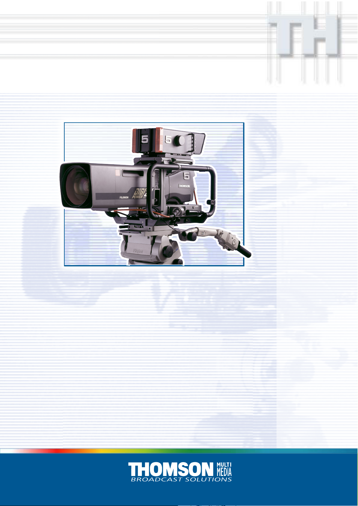
LDK 23hs mkiiLDK 23hs mkii
LDK 23hs mkii
LDK 23hs mkiiLDK 23hs mkii
High Speed Camera System
Operator’s Manual
3922 496 49011 St. 44
Page 2

Declaration of Conformity
We, Thomson Broadcast Solutions Nederland B.V., Kapittelweg 10, 4827 HG Breda, The Netherlands declare under
our sole responsibility that this product is in compliance with the following standards:
EN60065
EN55103-1
EN55103-2
following the provisions of:
a. the Safety Directives 73/23//EEC and 93/68/EEC
b. the EMC Directives 89/336/EEC and 93/68/EEC
: Safety
: EMC (Emission)
: EMC (Immunity)
FCC Class A Statement
This product generates, uses, and can radiate radio frequency energy and if not installed and used in accordance with
the instructions, may cause interference to radio communications.
It has been tested and found to comply with the limits for a class A computing device pursuant to Subpart J of part 15
of FCC rules, which are designed to provide reasonable protection against such interference when operated in a commercial environment.
Operation of this product in a residential area is likely to cause interference in which case the user at his own expense
will be required to take whatever measures may be required to correct the interference.
Copyright
Für diese Unterlage behalten wir uns
alle Rechte vor (Gemäß DIN 34).
Technische Änderungen im Zuge der
Weiterentwicklung vorbehalten.
© Thomson Multimedia Broadcast Solutions 2002
Copying of this document and giving
it to others, and the use or communication of the contents thereof,
are forbidden without express authority. Offenders are liable to the
payment of damages. All rights are
reserved in the event of the grant of
a patent or the registration of a utility
model or design. Liable to technical
alterations in the course of further
development.
Toute communication ou reproduction de ce document, toute exploitation ou communication de son
contenu sont interdites, sauf autorisation expresse. Tout manquement à cette règle est illicite et
expose son auteur au versement de
dommages et intérêts. Tous nos
droits sont réservés pour le cas de la
délivrance d'un modèle d'utilité. Sous
réserve de modification au cours de
l'évolution technique.
Page 3

LDK 23HS MkII
Portable EFP - Studio High Speed Camera system
Operator's Manual
Contents
About this Manual ................................................. ii
Introduction ...................................................... 1-1
Technology ........................................................ 1-2
Features ............................................................ 1-3
Important Precautions ........................................ 1-4
Assembling the Units....................................... 2-1
Transport Case .................................................. 2-2
Lens ................................................................... 2-3
1.5-inch Viewfinder ............................................. 2-4
Fitting accessories to the 1.5-inch viewfinder ..... 2-7
Other viewfinders ............................................... 2-8
Microphone ........................................................ 2-9
Camera Tripod ................................................. 2-10
Rain and Off-use Cover .................................... 2-11
SuperXpander .................................................. 2-12
Shoulder Pad ................................................... 2-13
Scriptboard ...................................................... 2-13
Top Light .......................................................... 2-14
Configurations ................................................. 3-1
Single camera triax mode .................................. 3-2
Multiple camera mode ........................................ 3-3
High Speed Recording ........................................ 3-4
High speed system compatibility ...................... 3-5
Required Software Configurations ...................... 3-6
Other Control Features ....................................... 3-7
Two-wire Data Control Bus ................................. 3-7
Video Routing .................................................... 3-8
Audio/Intercom Routing ...................................... 3-9
Location of Controls and Functions ............... 4-1
Power Supply ..................................................... 4-2
Video Functions ................................................. 4-3
Monitoring Functions .......................................... 4-5
Viewfinder .......................................................... 4-7
Viewfinder Indicators .......................................... 4-8
Control Functions ............................................... 4-9
Audio / Intercom .............................................. 4-10
Auxiliary Functions .......................................... 4-12
CPU output Functions ...................................... 4-13
Shooting ........................................................... 5-1
Using the Camera .............................................. 5-2
Standard settings ............................................... 5-2
Colour Bar .......................................................... 5-3
Gain selection .................................................... 5-3
Optical filter selection ........................................ 5-4
Colour temperature selection .............................. 5-4
Auto-White Balance ........................................... 5-5
Clean Scan ........................................................ 5-5
Artificial light conditions ..................................... 5-6
Operating the Menu System ............................ 6-1
Introduction ........................................................ 6-2
Systems Menu................................................... 6-3
Appendix ..........................................................A-1
Menu Structure ................................................. A-3
Operate Menu ................................................ A-3
Setup Menu ................................................... A-4
VF/Lens Menu ............................................... A-6
Install Menu................................................... A-7
Diagnostic Menu ............................................ A-8
Files Menu .................................................... A-8
List of Menu Functions...................................... A-9
02.35.1 Operator's Manual LDK 23HS mkII - HS camera System i
Page 4

About this Manual
This Operator's Manual is part of a complete
documentation set for the camera system which also
includes an Installation and Service Manual.
Purpose of this manual
The purpose of this manual is to present a detailed
description of how to operate the LDK 23HS mkII EFP
- Studio Camera. It provides the information necessary
to use the camera system in different configurations
and with various attachments. With this manual it is
possible to discover the operating features of the
camera system and so use it to its full potential. The
manual should be used together with the camera
system to explore and learn about the many
sophisticated control functions available.
Intended audience
This Operator's Manual can be used by inexperienced
camera operators who are new to Thomson Multimedia
Broadcast Solutions cameras as well as those who
have previous experience of operating cameras. The
guide is so designed that it can be used as an
introduction to those who are new to the camera
system, as a simple procedural guide to those who
wish to setup and start shooting immediately, and as
a reference work to be consulted as required during the
long life of the camera system.
Section 4: Location of Controls and Functions
This section shows the physical location of the controls
and connectors on the camera system. These are
grouped according to their function so as to provide a
quick reference guide to the operation of a particular
aspect of the camera system.
Section 5: Shooting
This section contains information on the practical use
of the camera system using the viewfinder display and
the switches at the front and front-left to control the
camera.
Section 6: Operating the Menu System
Because the LDK 23HS mkII offers such a wide range
of functions, this section describes the structure of the
control system. It contains procedures for controlling
the menu system and explains how to program the
menu system for your personal preferences. The
menu structure and the methods of function selection
are also explained.
Appendix
The appendix contains a list of the menu functions
available on the camera.
Structure of this manual
The manual is divided into six sections and an appendix:
Section 1: Introduction
This section outlines the technology used in the
LDK 23HS mkII camera system and how this translates
into a practical, useable camera system. It lists the
main features of the camera system and also the
precautions that must be taken into account when
using it.
Section 2: Assembling the Units
Section 2 provides information on the physical
assembly of the camera system and on how
accessories can be used to expand the possibilities of
the camera system. The mounting of accessories and
packing for transport is also explained.
Section 3: Configurations
The LDK 23HS mkII is a multi-functional camera
system and this section describes the various ways
that it can be used in a studio system with other
cameras. Information on the cables, control panels
and the control bus is also provided as is information
on the main video and audio signal paths through the
system.
ii Operator's Manual LDK 23HS mkII - HS Camera System 02.35.1
Page 5

Section 1
Introduction
This section outlines the technology used in the LDK 23HS mkII camera system and how this
translates into a practical, useable camera system. It lists the main features of the camera system
and also the precautions that must be taken into account when using it.
Contents
Technology ........................................................ 1-2
Features ............................................................ 1-3
Introduction Operator's Manual LDK 23HS mkII - HS Camera System 1-1
Important Precautions ........................................ 1-4
Page 6

Technology
The LDK 23HS mkII is a lightweight EFP/Studio high
speed camera system which uses 2/3" frame transfer
sensors with Dynamic Pixel Management (DPM).
Super Slow Motion
Unique live slow motion capability. The LDK 23 HS
mkII scans at three time the normal rate. Instead of
scanning at 50 Hz for PAL and 60 Hz for NTSC the LDK
23HS mkII scans at 150 Hz for PAL and 180 Hz for
NTSC.
Various preset settings for artificial light conditions
ensure a slow motion picture without pulsing light
effects.
Sensor technique
Frame Transfer Dynamic Pixel Management allows
the format of the sensors to be switched between 4:3
and 16:9 aspect ratio at the touch of a switch without
loss of horizontal resolution. The 1000 pixels per line
in both formats ensures that there is no loss in
horizontal viewing angle.
Another aspect of the 2/3" DPM sensors is that there
is no loss of vertical resolution between formats. They
have a highlight compression/dynamic range of 400%
and a high linear sensitivity over all camera lens
apertures. The frame transfer technology ensures that
there is no lag nor smear.
Advanced Triax Features
The Triax system allows remote control of camera up
to a distance of 800 meters (1000 meter with minor
performance degration). The Triax system uses YUV
transmission.
The communication facilities provide for two-wire or
four-wire high quality intercom signals.
The LDK 23 HS mkII is compatible with the existing
Thomson Multimedia Broadcast Solutions Series 9000
Universal Camera Control system. Base station outputs
include triple and normal scan serial digital video
signals.
SuperXPander
The optional LDK 4482 SuperXpander enables the
camera to be used with large lenses so extending the
camera's use in studio and EFP situations.
The Intelligent Continuous Automatics facility provides
automatic control of black levels and black shading.
Each DPM sensor has two lines of sensor elements
that are protected from incoming light and therefore
give a true indication of black. The black reference
signal that they provide is used in the camera
preprocessor circuits to monitor temperature changes
which, if not corrected, would alter the black level. In
this way continuous automatic correction is applied
without operator intervention.
Film-like characteristics
To achieve film-like quality it is necessary to emulate
the softly limiting S-shaped transfer characteristics of
film. This is done by compressing the TV camera's
near linear characteristics above a certain point, the
knee. The pivoting knee circuit of the LDK 23HS mkII
camera system adapts both the knee point and the
compression ratio according to the highlight content of
the picture. Significant highlights lower the knee point
to give more room for compression, while minor
highlights only affect the upper part of the transfer
characteristic. Signals below the knee point remain
unaffected. As a result, compression is only applied
where necessary and in proportion to the highlight, and
the pictures obtained have true film-like quality.
1-2 Operator's Manual LDK 23HS mkII - HS Camera System Introduction
Page 7

Features
• Triple speed scanning for superb slow motion replay.
• Instant replay through almost any disk based slowmotion system.
• Various preset settings for artificial light conditions
ensure a slow motion picture without pulsing light
effects.
• DPM Frame Transfer sensors with 1000 horizontal
pixels in 4:3 and 16:9 aspect ratios, and the same
number of vertical lines in both formats.
• No change in horizontal viewing angle - so no wide
angle convertors required.
• Simple no-compromise switching between 4:3 and
16:9 - future proof concept with no later upgrades
needed for either camera or lenses.
• Automatic selection of correct viewfinder mode for
4:3 and 16:9.
• Intelligent Continuous Automatic black levels, black
shading and video levels - no setup time required.
• Highlight compression with a dynamic range of up to
400%.
• International standard 2/3-inch lens interface.
• 6-position standard filter wheel cassette,
exchangeable.
• Low centre of gravity and optical path for ease of
production use.
• Short, lightweight portable camera with integrated
triax system for EFP use.
• Extensive two-wire or four-wire intercom to
international standards.
• Protected, easy-to-operate controls and switches
• Viewfinder status read-out of primary camera
functions
• Clear scan feature allows capture of computer and
other monitor pictures.
• Triax system allows for cable lengths up to 800
meters (1000 meters with minor performance
degration).
• Digital RS 232 data transmission over triax system
for robotics and other applications.
Introduction Operator's Manual LDK 23HS mkII - HS Camera System 1-3
Page 8
Important Precautions
To ensure continual high performance from the LDK
23HS mkII camera take the following precautions into
consideration:
Avoid very damp places. If the
environment is wet or damp a
raincover must be used to protect it.
Do not subject the unit to severe
shocks or vibration.
Do not expose the camera to
extremes of temperature.
Do not leave the unit in direct
sunlight or close to heating
appliances for extended periods.
Do not allow sunlight to shine into
the viewfinder.
Avoid extreme highlights as these
can cause various kinds of optical
reflections.
Warnings
If the LDK 23HS mkII is in a wet or damp environment,
a raincover must be used to protect it for personal
safety reasons (EN60065). The raincover LDK6988/
00 protects the camera according to safety specification EN60529 up to level IPX3 (spraying water).
1-4 Operator's Manual LDK 23HS mkII - HS Camera System Introduction
Page 9

Section 2
Assembling the Units
Section 2 provides information on the physical assembly of the camera system and on how
accessories can be used to expand the possibilities of the camera system. The mounting of
accessories and packing for transport is also explained.
Contents
Transport Case .................................................. 2-2
Lens ................................................................... 2-3
1.5-inch Viewfinder ............................................. 2-4
Fitting accessories to the 1.5-inch viewfinder ..... 2-7
Other viewfinders ............................................... 2-8
Microphone ........................................................ 2-9
Assembling the Units Operator's Manual LDK 23HS mkII - HS Camera System 2-1
Camera Tripod ................................................. 2-10
Rain and Off-use Cover .................................... 2-11
SuperXpander .................................................. 2-12
Shoulder Pad ................................................... 2-13
Scriptboard ...................................................... 2-13
Top Light .......................................................... 2-14
Page 10
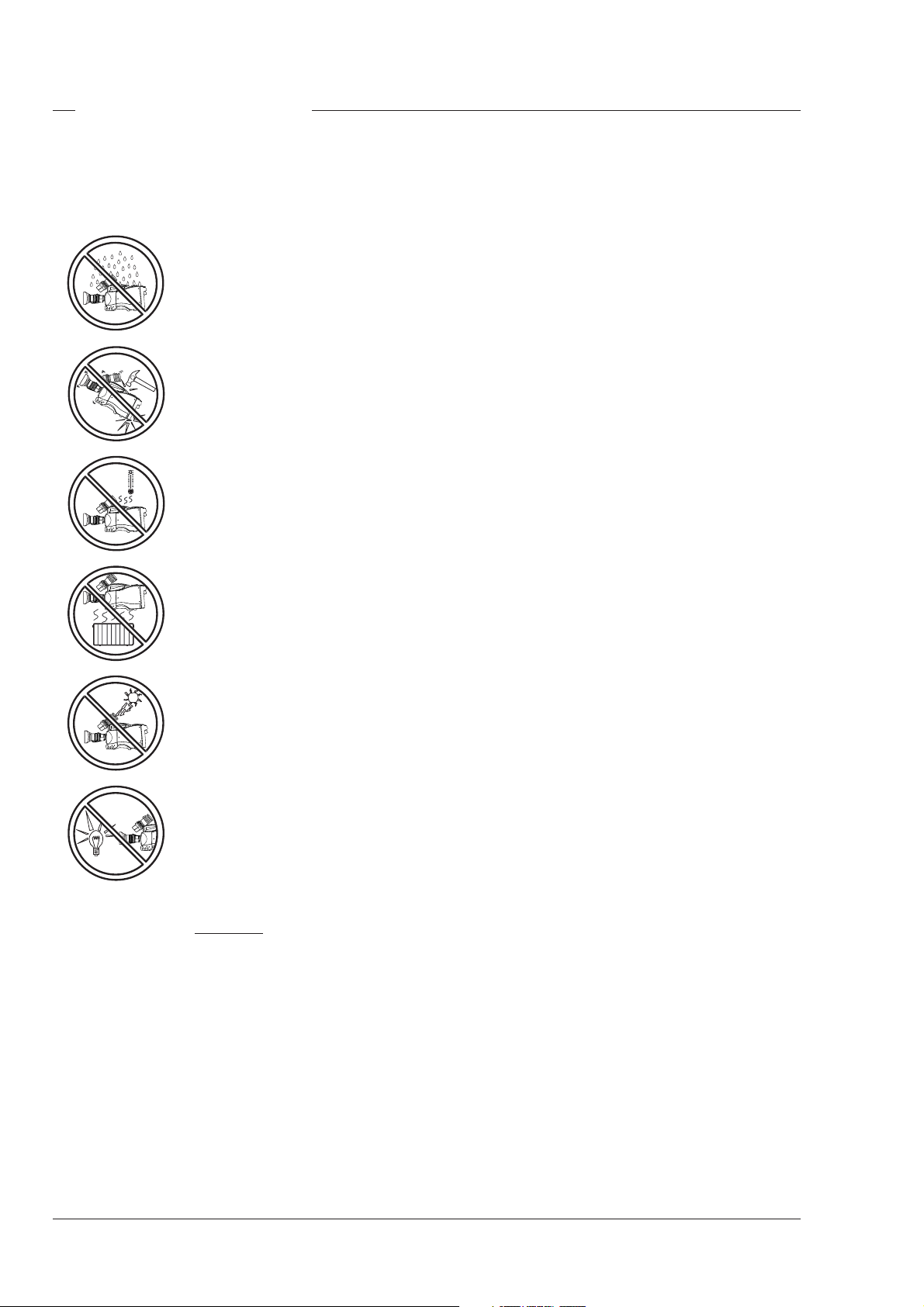
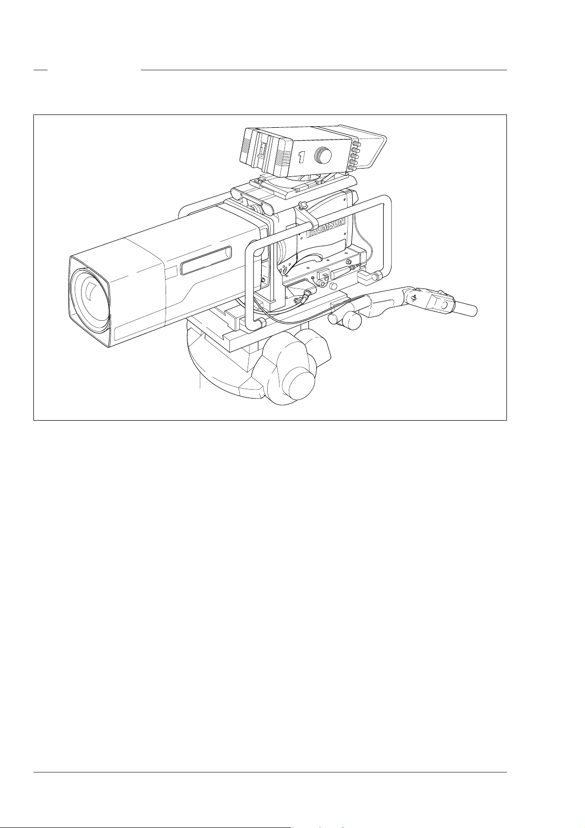
Transport Case
THS 1368
It is important to protect your camera against damage
when transporting it. To do this, a transport case is
available for the camera, lens, viewfinder and some
accessories.
The camera is packed in the transport case as shown
in the figure above. This ensures that the camera is
not damaged during transport. Do not forget to secure
the straps around the items to keep them in place.
2-2 Operator's Manual LDK 23HS mkII - HS Camera System Assembling the Units
Page 11
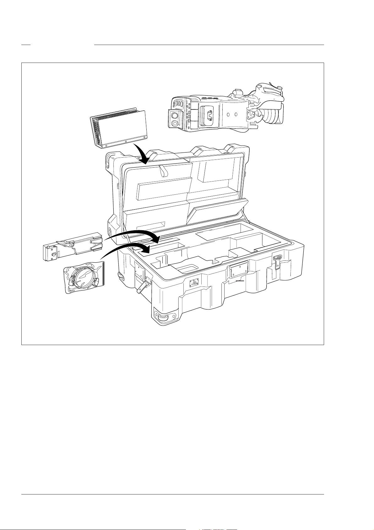
Lens
LDK23HS
1 2
HIGH SPEED
LDK23HS
mk II
SUPER SLOW MOTION
6
5
4
3
To attach a lens to the camera head proceed as
follows:
a. Ensure that the lens locking ring (1) is in the
unlocked position - turned counterclockwise.
b. Remove the dust protection cap (2).
c. Slot the lens into the lens mount (3).
d. Turn the lens locking ring (1) clockwise to lock the
lens in place.
e. Connect the lens cable to the lens connector (4) at
the right side of the camera.
f. Clip the lens cable into the clip (5) provided.
THS1370
Caution
Do not attach a lens weighting more
than 5 kg to the camera without a support.
Caution
Do not attach a lens to the Viewfinder
connector (6).
Note
Always mount the dust protection cap when the
lens is not connected to the camera.
Assembling the Units Operator's Manual LDK 23HS mkII - HS Camera System 2-3
Page 12
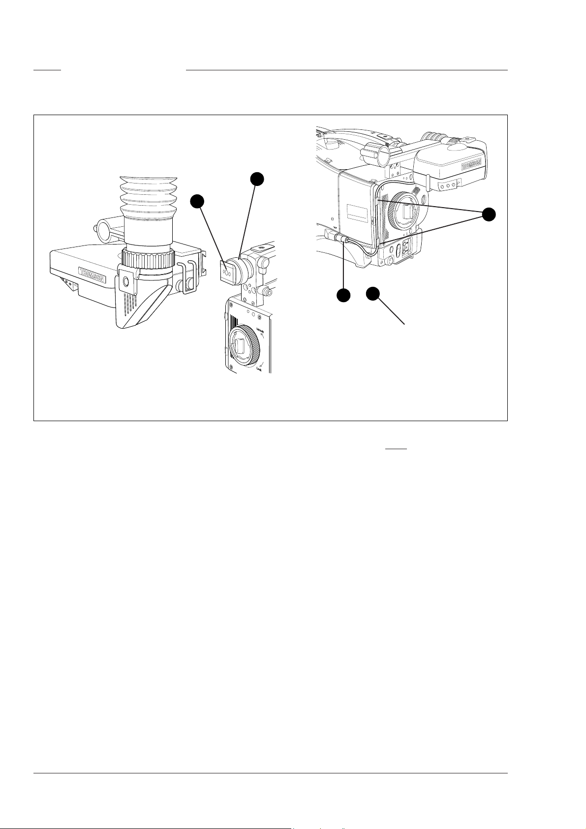
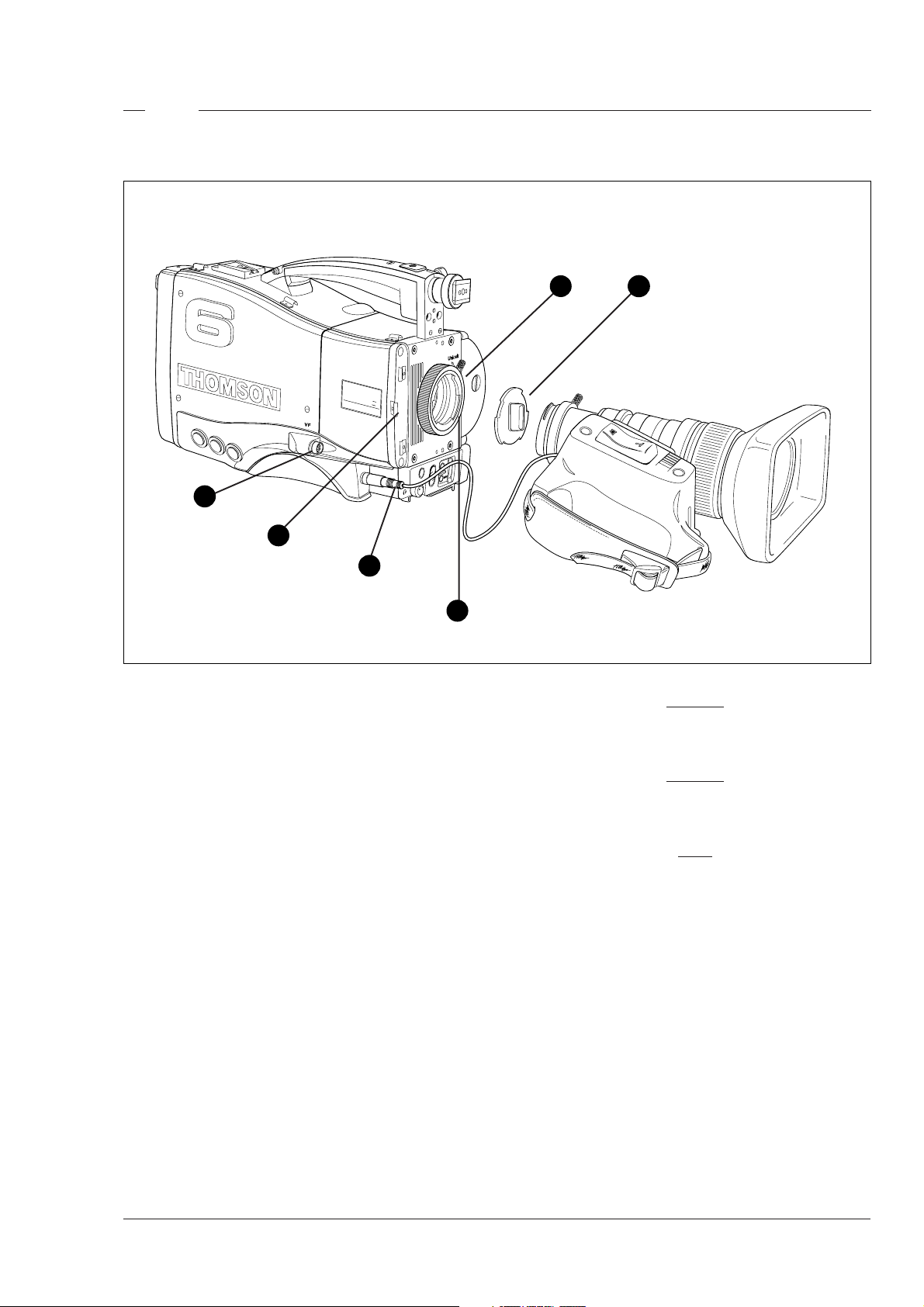
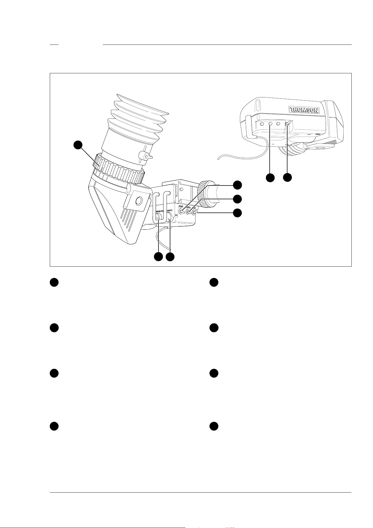
1.5-inch Viewfinder
Mounting the optional 1.5-inch viewfinder
1
2
To mount the optional 1.5-inch viewfinder proceed
as follows:
a. Loosen retaining screw (1) of viewfinder support
bracket (2) at the front of the camera handle.
b. Slide the viewfinder onto the viewfinder support
bracket.
c. Tighten the support bracket retaining screw (1)
by turning it clockwise so that the viewfinder is
mounted securely to the support.
d. Connect the viewfinder cable to the viewfinder
connector (3) at the right side of the camera.
e. Clip the viewfinder cable into the clips (4)
provided.
HIGH SPEED
LDK23HS mk II
3
SUPER SLOW MOTION
5
4
THS 1372
Note
When dismounting the viewfinder push in retaining
clip (5) on the slide to remove the viewfinder from
the support bracket (2).
2-4 Operator's Manual LDK 23HS mkII - HS Camera System Assembling the Units
Page 13
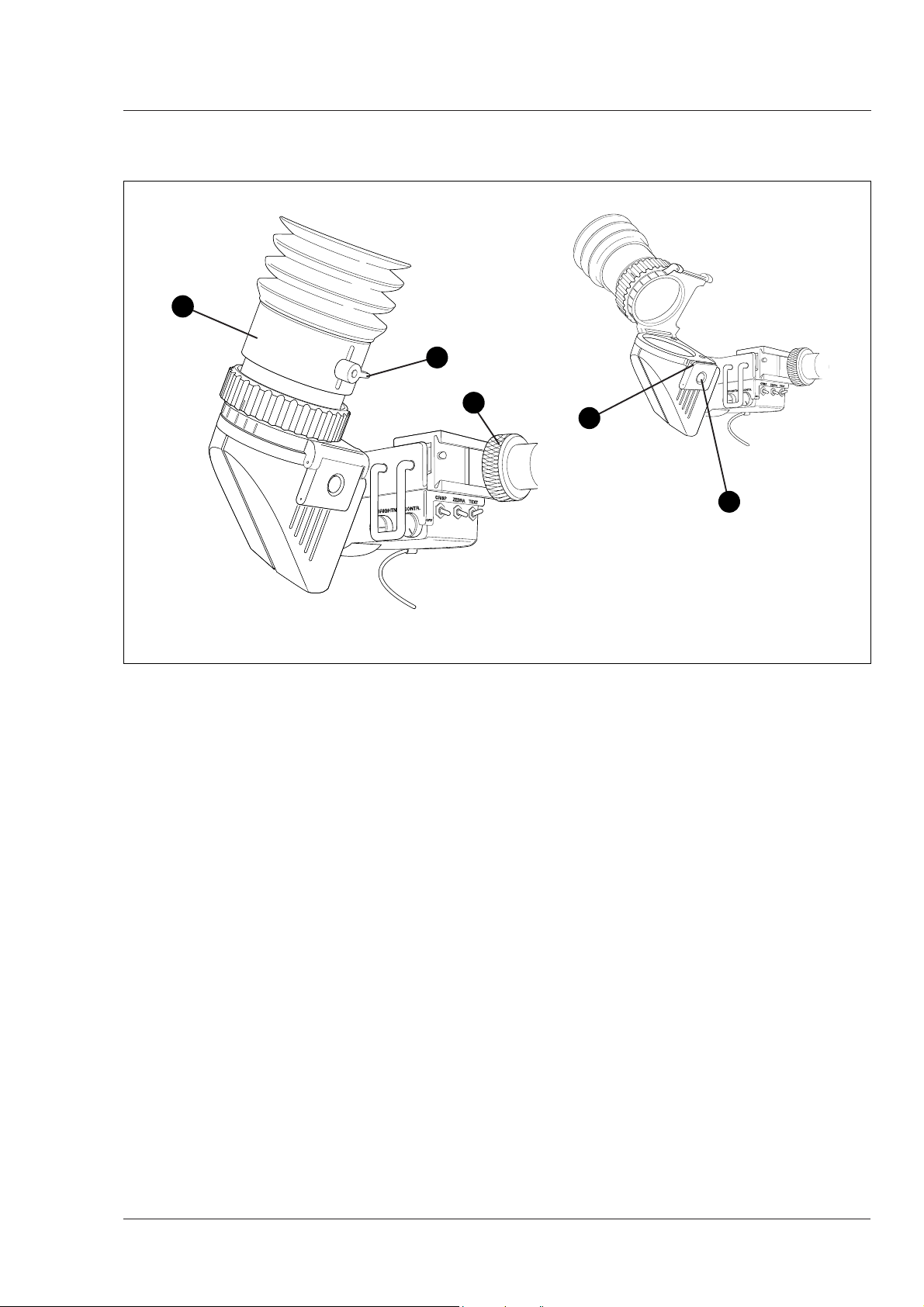
Positioning the optional 1.5-inch viewfinder
2
3
The horizontal position of the viewfinder can be
adjusted to suit your requirements:
a. Loosen the support bracket retaining screw (1).
b. Slide the viewfinder horizontally along the rail to
the desired position.
c. Tighten the support bracket retaining screw (1).
The dioptre hood and eyepiece of the viewfinder can
be rotated vertically.
1
5
THS 1374
4
The length of the eyepiece tube (2) can also be
adjusted by loosening securing lever (3) and moving
the tube back or forward.
To use the viewfinder at a distance press the button
(4) below or above the eyepiece tube and swing it free
of the associated clip (5). The display can now be
seen from further away.
Assembling the Units Operator's Manual LDK 23HS mkII - HS Camera System 2-5
Page 14
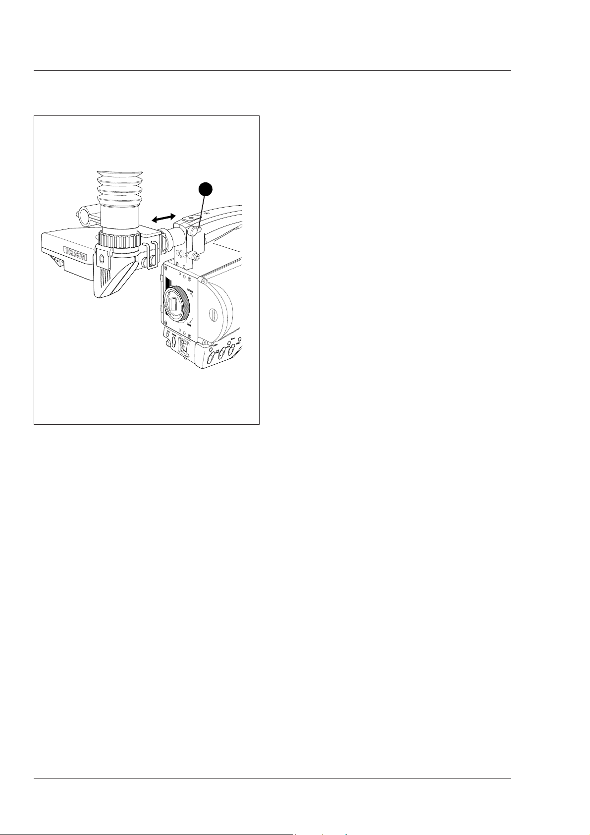
Positioning the optional 1.5-inch viewfinder
1
The front-back position of the viewfinder can be
adjusted to suit your requirements:
a. Loosen the viewfinder front-to-back positioning
lever (1).
b. Slide de viewfinder longitudinally to the most
convient position for viewing.
c. Tighten the viewfinder front-back posititioning lever
(1).
2-6 Operator's Manual LDK 23HS mkII - HS Camera System Assembling the Units
Page 15
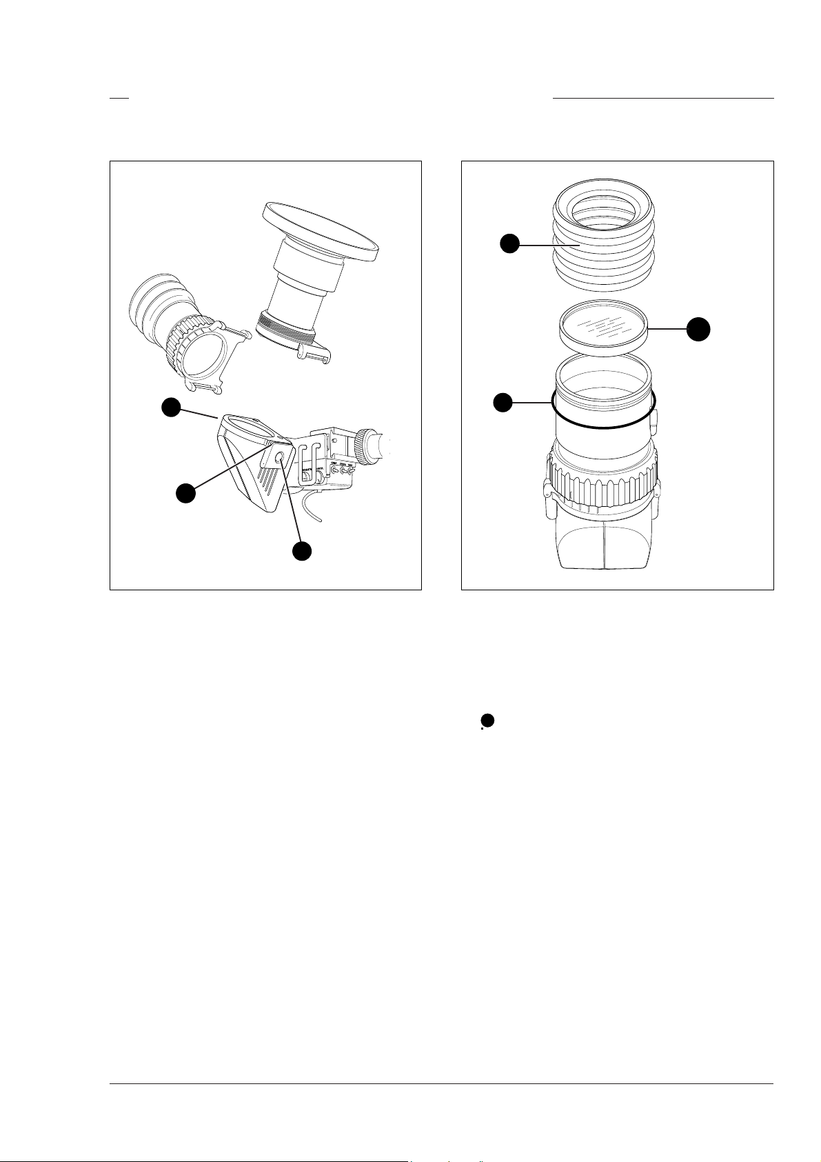
Fitting accessories to the 1.5-inch viewfinder
Wide angle ocular Anti-misting Optic
2
3
3
2
1
If you regularly use the viewfinder at a distance, for
example when you use the camera in the hand-held
position, it is recommended that you fit the Wide Angle
Ocular LDK 6108/10. To fit a wide angle eyepiece
proceed as follows:
a. Hold the eyepiece securely.
b. Press the button (1) below the eyepiece tube and
swing it free of the bottom clip (2).
c. Press the button (3) above the eyepiece tube and
remove the eyepiece.
d. Fit the wide angle eyepiece to the two clips (2)
ensuring that it clicks into place.
1
If the camera is used in damp conditions or if the
viewfinder picture is obscured by condensation on the
eyepiece, it is recommended that you fit the Antimisting Optic LDK 6108/90 in front of the eyepiece. To
fit an anti-misting optic proceed as follows:
a. Remove the rubber ring (1) securing the bellows
2
to the eyepiece.
b. Remove the bellows (2).
c. Screw the anti-misting optic (3) onto the eyepiece.
d. Secure the bellows (2) to the eyepiece using the
rubber ring (1).
Assembling the Units Operator's Manual LDK 23HS mkII - HS Camera System 2-7
Page 16
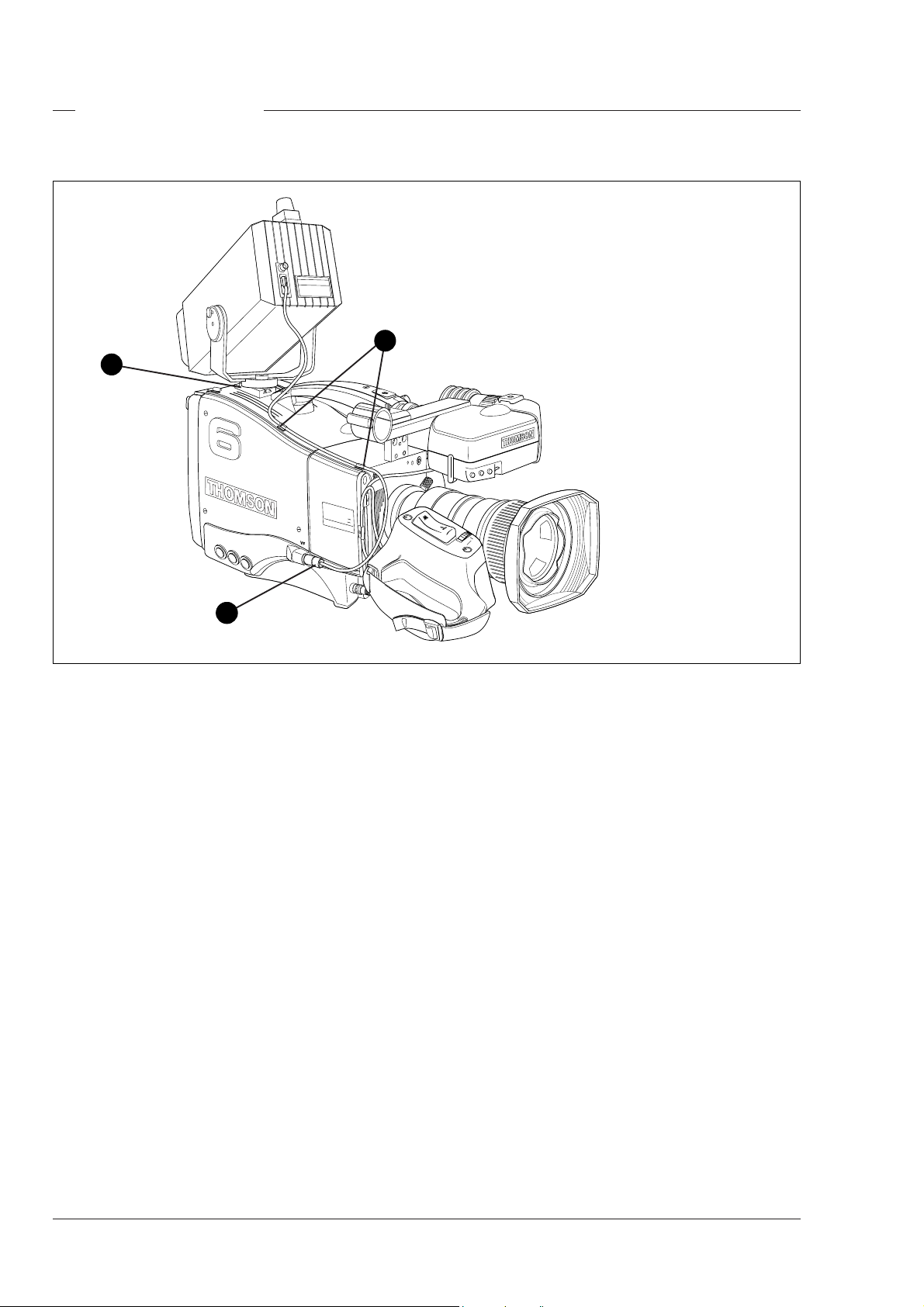
Other viewfinders
SUPER SLO
W MO
TION
HIGH SPEED
LDK23HS
mk II
5-inch viewfinder
1
HIGH SPEED
LDK23HS
mk II
SUPER SLO
W MO
TION
3
2
In many EFP and studio situations the optional 5-inch
viewfinder LDK 4309/15/16/55/56 is used instead of
the 1.5-inch viewfinder. The 5-inch viewfinder is
mounted in the slot (1) at the top-rear of the camera
head. The viewfinder cable is connected to the
viewfinder connector (2) at the right side of the camera.
The cable is placed in the clips (3).
For full information on the optional 5-inch viewfinder
refer to the User's Guide supplied with the viewfinder.
2-8 Operator's Manual LDK 23HS mkII - HS Camera System Assembling the Units
Page 17
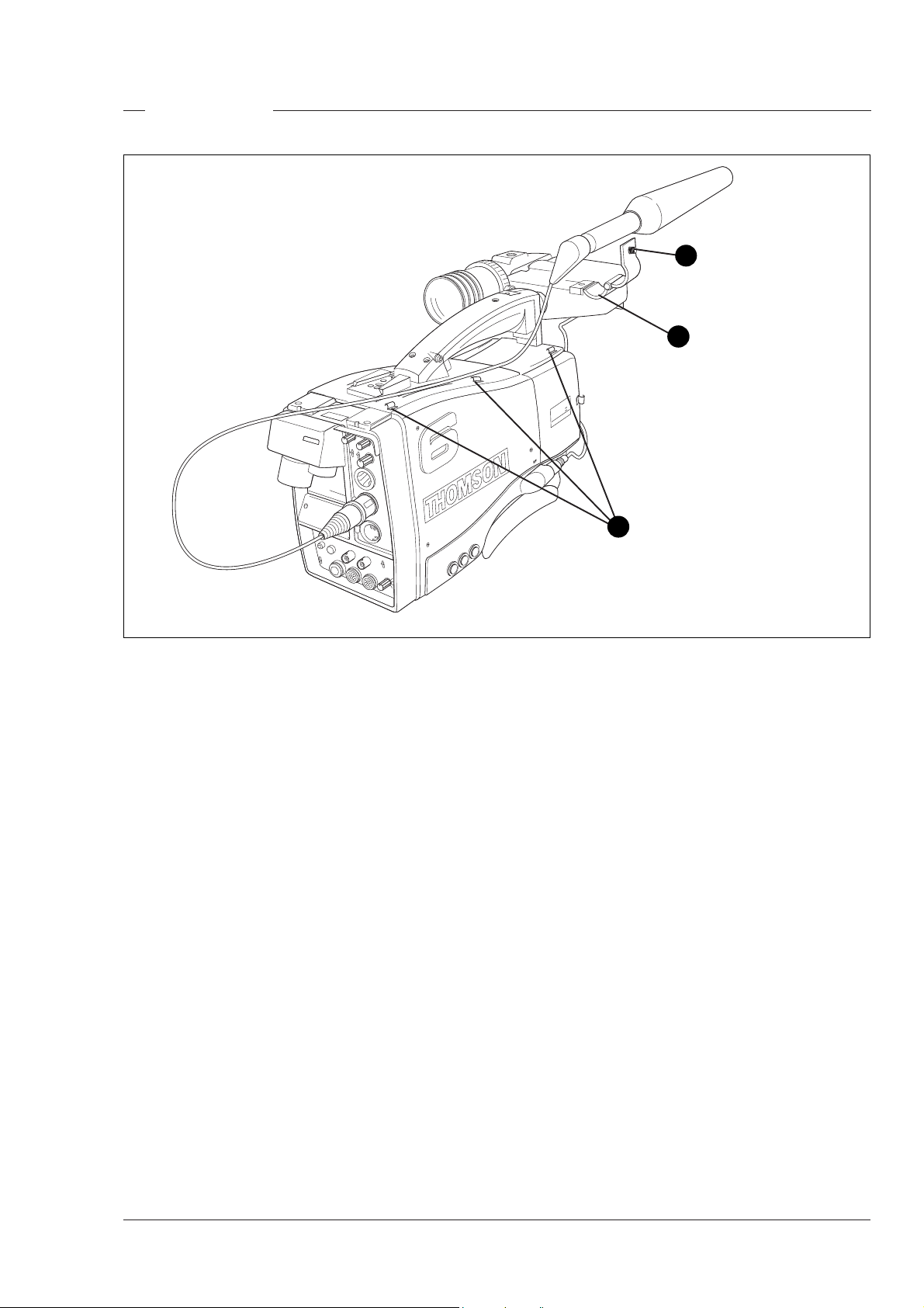
Microphone
1
2
mk II
N
HIGH SPEED
MOTIO
W
LDK23 -
PER SLO
SU
01
02
3
To attach a microphone, the LDK 8330/00 for example,
to the camera proceed as follows:
a. Loosen the retaining screw (1) of the microphone
support bracket (2) on the viewfinder and open.
b. Place the microphone into the support bracket (2).
c. Close the bracket and tighten the microphone
bracket retaining screw (1).
d. Connect the microphone cable to audio connector
1 or 2 at the rear of the camera.
e. Clip the microphone cable into the slot (3) in the
handle of the camera.
Other microphones can also be used, however, ensure
that the phantom power and the sensitivity are set
correctly for the type of microphone in use. Refer to
the installation manual for more information on
selecting the phantom power supply. The audio level
is selected using the camera control system (refer to
Section 6).
THS 1379
Assembling the Units Operator's Manual LDK 23HS mkII - HS Camera System 2-9
Page 18
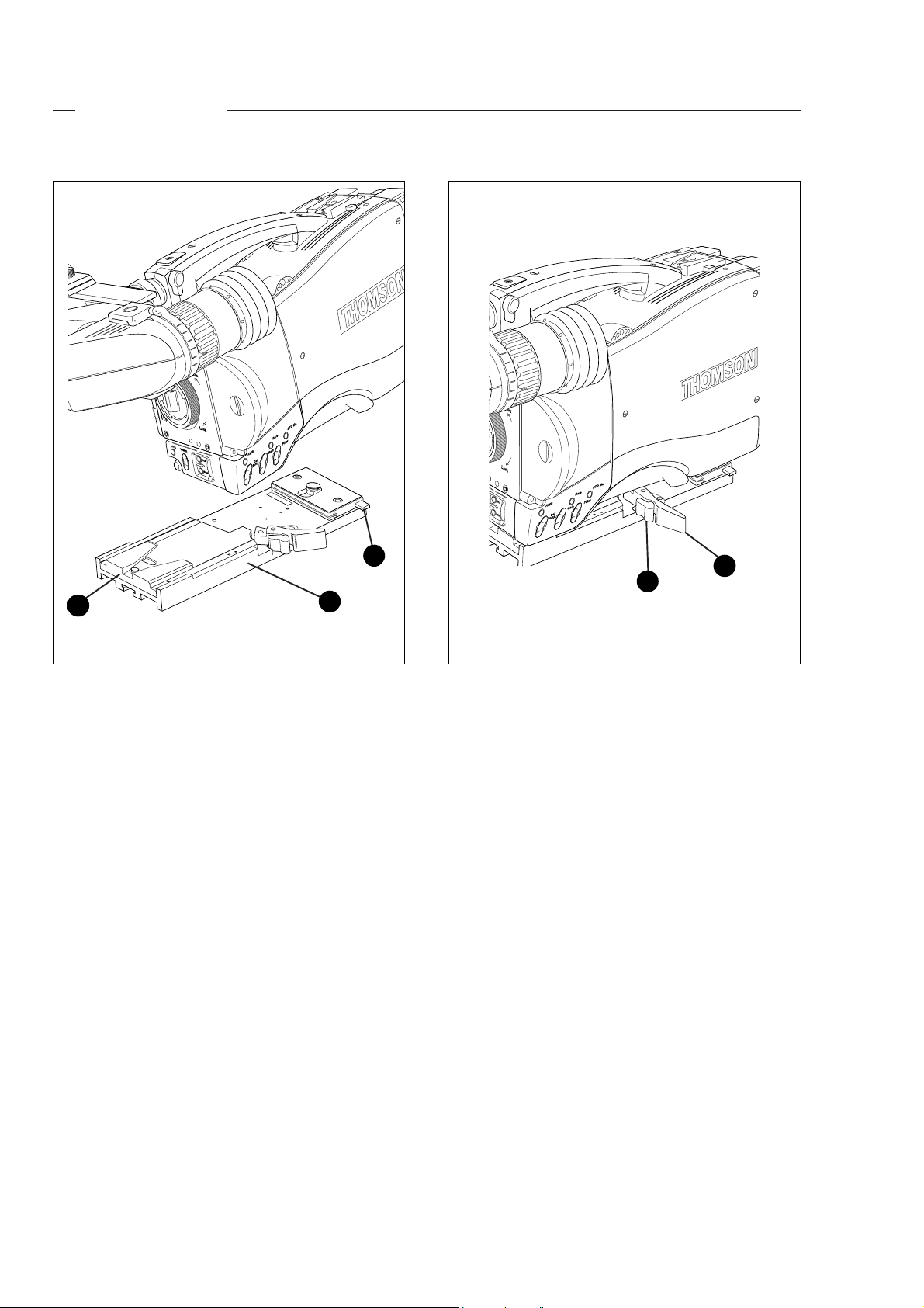
Camera Tripod
3
2
To mount the optional tripod adapter LDK 5031/00
onto the tripod and the camera onto the tripod adapter
proceed as follows:
a. Secure the tripod adapter (1) to the tripod wedge
plate using the screws supplied with the tripod.
Screws with threads of 3/8 inch, M4 or M8 can be
used with the tripod plate. Use two screws if
possible to ensure a secure mount.
b. Mount the two plates on the tripod.
c. Clip the front of the camera in under the lip (2) at
the front of the tripod plate and firmly push the
camera downwards and forwards until it clicks into
place.
d. Push lever (3) in the lock direction until the camera
is set firmly.
Caution
Failure to attach the camera to the
tripod plate in the correct manner could
result in an unsecured camera. Ensure that it
1
1
2
clicks into place.
To remove the camera from the tripod proceed as
follows:
a. Press the red locking lever (1) against release
handle (2) on the tripod adapter and hold.
b. Pull the release handle (2) forward.
c. The camera will spring free of the tripod adapter.
2-10 Operator's Manual LDK 23HS mkII - HS Camera System Assembling the Units
Page 19
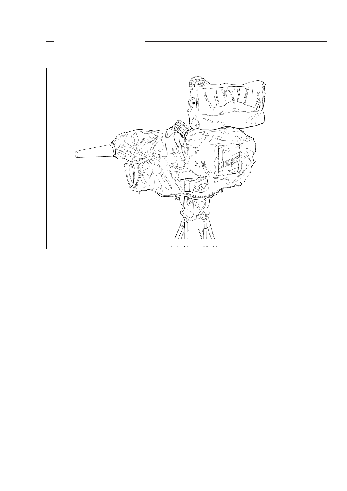
Rain and Off-use Cover
STD file
Gain
AWB
Bars
Col
temp
T
file
CLS
STD
ars
B
B
AW
Filter
ain
G
ol
C
p
tem
The rain and off-use cover LDK 6989/00 must be used
when the camera system is in a wet or damp
environment. This protection is necessary for personal
safety reasons.
The cover can also be used indoors to protect the
camera when it is used in dusty environments. It can
also be useful if the camera is being put into storage.
For more information on how to put on the cover refer
to the User's Guide which is supplied with it.
Assembling the Units Operator's Manual LDK 23HS mkII - HS Camera System 2-11
Page 20
SuperXpander
AWB
Bars
STD file
Gain
Filter
D file
T
S
ars
B
r
lte
Fi
WB
A
Gain
The SuperXpander (LDK 4482) for the LDK 23HS
mkII extends the camera's use in studio and EFP
situations. This adapter allows larger studio lenses
and a 7-inch viewfinder to be used with the camera.
Additional facilities provided include a utility power
outlet and a rear control panel.
Refer to the User's Guide of the large lens adapter for
more information on mounting the camera and other
units to the large lens adapter as well as information
on the additional functions of the adapter.
THS 1383
2-12 Operator's Manual LDK 23HS mkII - HS Camera System Assembling the Units
Page 21
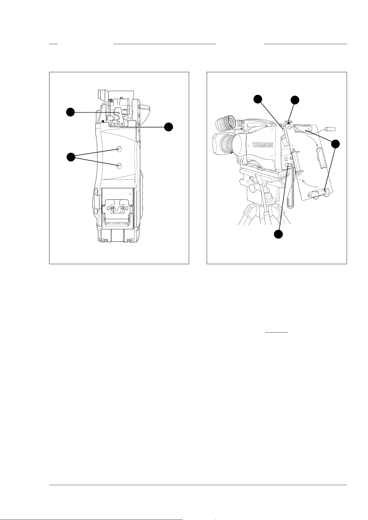
Shoulder Pad
Scriptboard
3
2
1
To mount another type of shoulder pad proceed as
follows:
a. Remove the two screws (1) securing the shoulder
pad to the camera.
b. Slide the lip (2) of the new shoulder pad under the
triangular bracket (3). Use the two screws (1) to
secure it in place.
3
1
4
THS 1385
2
To mount the scriptboard LDK 6985/15 onto the
camera proceed as follows:
a. Secure the scriptboard to the top-rear of the camera
with the retaining screw (1).
b. Connect scriptboard light cable to the scriptlight
connector (2) at the rear of the camera.
Caution
Ensure that the scriptlight does not
use more than 3W of power.
The scriptlight is switched on and off, and the intensity
is varied with the knob (3) at the rear of the scriptboard.
The retaining rings and clip (4) can be screwed onto
the right and left side resp. if required.
Assembling the Units Operator's Manual LDK 23HS mkII - HS Camera System 2-13
Page 22

Top Light
1
2
To mount a toplight on the camera, proceed as
follows:
a. Raise the recessed bracket (1) by tightening screw
(2).
b. Screw or slide the toplight onto the bracket (1) and
lock the toplight.
c. Adjust the angle of the bracket (1) by loosening or
tightening the screw (2).
d. When no toplight is mounted, loosen screw (2) to
lower the bracket (1) for a smooth handgrip.
2-14 Operator's Manual LDK 23HS mkII - HS Camera System Assembling the Units
Page 23

Section 3
Configurations
The LDK 23HS mkII is a multi-functional camera and this section describes the various ways that
it can be used in a studio system with other cameras. Information on the cables, control panels and
the control bus is also provided as is information on the main video and audio/intercom signal paths
through the system.
Contents
Single camera triax mode .................................. 3-2
Multiple camera mode ........................................ 3-3
High Speed Recording ........................................ 3-4
High speed system compatibility ...................... 3-5
Required Software Configurations ...................... 3-6
Configurations Operator's Manual LDK 23HS mkII - HS Camera System 3-1
Other Control Features ....................................... 3-7
Two-wire Data Control Bus ................................. 3-7
Video Routing .................................................... 3-8
Audio/Intercom Routing ...................................... 3-9
Page 24

Single camera triax mode
Two-wire data cable,
maximum length:
350 m (1,150 ft.)
LDK 23HS mkII
THS 1387
Triax cable,
maximum length:
800 m with 14 mm cable
(1000 m with minor
performance degradation)
This configuration is the single camera Triax (Remote)
mode. In this case the camera is connected to a CPU
via a Triax cable which can have a maximum length
of 800 m with 14mm cable (1000 m with minor
performance degradation). The CPU provides the
power supply for the camera via the Triax cable. The
CPU receives its power from the AC mains supply.
The Triax cable carries R-Y, Y and B-Y video signals,
two audio signals and intercom signals from the
camera head to the CPU. It also carries external
video signals, and intercom signals from the CPU to
the camera.
CPU
LDK 4058
Camera Processing Unit HS mkII
Mains
AC power supply
Series 9000 THOMSONOCP
Pan lock
Cam pwr
OCP pwr
Gen lock
Camera
Triax
Base St
Non standard
Exposure Gamma Monitoring
Preset
1
R
60 Hz
G
2
50 Hz
Var
B
Nom
Sup
Lin
1/200
1/500
CVBS
1/1000
Seq
Variable
Saturation
Wh clipBlk strBlk strSawGamma Flare
Operational
Contour Var
Knee
Lev depVar Bars Contour
Slope
Auto Auto wh Auto blk
Auto Auto wh Auto blk
Point
Point
Col Temp GainFilter
1/Clr
Aw 1
2
Aw 2
3
7500 K
4
5600 K
5
6
3200 K
7
8/Cap
Gain
0
CABLE TEST
CAM ON
AC
ON AIR
DC
mains
Black
Iris
Auto iris F-Number
On air
Scene file
12
34
Free
Standard
Store
Call
Control
V-level Level
V-level Level
Panel
++
+
0
OCP
Centre
Extender
Range
Cam select
8
115
Preview
Master
black
Mains of OCP
AC power supply
Remote control of the camera when used in the Triax
mode is achieved by a remote control panel of the
Series 9000 Control System. This can be an
operational control panel (OCP) connected to the
CPU. The data communication between camera and
CPU is carried over the Triax cable. The control panel
can also be connected directly to the camera.
3-2 Operator's Manual LDK 23HS mkII - HS Camera System Configurations
Page 25

A
WB
B
ar
s
ST
D
fi
l
e
G
a
i
n
Filt
e
r
Multiple camera mode
LDK 200
1
A
Clear
Clear
ND1/4
Star 4P
2
B
ND1/16
Star 6P
3
C
ND1/64
Soft Focus
4
D
VTR
Ext.
Std.
Save
Iris
File
l
P we
Power
on
LDK 23HS mkII
LDK 20
Data Cable (2-wire)
350 m (1,150 ft)
(2-wire)
(2-wire)
Maximum
Length
Operational Control Panels
MCP II
LDK4609
Base Station
Smart
card
Aux
Triax Cable
Tracker
2,400 m (7,875 ft)
with 14 mm cable
Maximum
Length
LDK 4500
Prod
Prog
THOMSON
Cam +Floor
Eng
Camera Base Station
Data Cable
CPU
LDK 4058 mkII
e
l
i
f
TD
S
s
r
a
B
er
t
l
i
F
WB
A
n
i
Ga
1000 m (3281 ft) with minor
performance degradation
Triax Cable
Maximum
Length
800 m (2,625 ft)
with 14 mm cable
Camera Processing Unit HS mkII
0
CABLE TEST
CAM ON
AC
ON AIR
DC
mains
Data Cable
Base Station
LDK 4500
Prod
Prog
THOMSON
Cam +Floor
Triax Cable
Maximum
Length
2,400 m (7,875 ft)
with 14 mm cable
Eng
Camera Base Station
This configuration is the multiple camera Triax mode.
The camera is connected to a CPU as in the single
camera Triax mode. The data bus is looped-through
from CPU to CPU's, Base Stations, OCP's and MCP.
The OCP's (Operational Control Panels) are used to
control the cameras and a MCP (master Control Panel)
can also be connected to extend the control facilities.
The LDK 20 and LDK 200 studio cameras are of course
ideal companions for the LDK 23HS mkII, however,
other cameras of the Thomson Multimedia Broadcast
Solutions family such as the LDK 10p, the LDK20P
and the LDK 100 can also be included in this
configuration.
MCP
LDK 4607
THS 1388
Note
A maximum of 15 looped-trough standard camera
systems in one chain can be handeld, however, in a
multiple system the load of a LDK 23 HS (mkII) is
twice the load of a standard camera so with level 1
communication software the system can handle a
maximum of 8 LDK23 HS (mkII) camera's.
Configurations Operator's Manual LDK 23HS mkII - HS Camera System 3-3
Page 26

High Speed Recording
LDK 23HS mkII
Operational Control Panels
OR
OCP
LDK4628
OR
Master Control Panels
MCP II
LDK4609
Camera Processing Unit HS mkII
Analoque Standard Outputs
Normal Scan RGB, YUV
(used for live and CVBS
(for monitoring)
CPU
LDK 4058 mkII
CAM ON
ON AIR
OCP
LDK 4629
MCP
LDK 4607
0
CABLE TEST
AC
DC
mains
Digital Standard Output,
SDI 270 Mb/s Normal Scan
(Used for PGM)
Digital Triple Scan
For High Speed
3x SDI 270 Mb/s
REMOTE
RS 422
Multi-Channel
Ph1,2 and 3
Disk Recorder for
Super Live Slow Motion
Standard PGM Output
270 Mb/s
(Used for Slow Motion)
Composite Output
(Used for monitoring)
3-4 Operator's Manual LDK 23HS mkII - HS Camera System Configurations
Page 27
High speed system compatibility
Camera Processing Unit HS mkII
+
THS 1387
CABLE TEST
CAM ON
AC
ON AIR
DC
23 HSmkII CPU LDK 4058 mkII version
Camera Processing Unit
+
THS 1387
CABLE TEST
CAM ON
AC
ON AIR
DC
23 HS mkII CPU LDK 4058 mkI version
Camera Processing Unit HS mkII
+
THS 1387
CABLE TEST
CAM ON
AC
ON AIR
DC
23 HS mkI CPU LDK 4058 mkII version
0
mains
mains
mains
= 23 HS mkII operation
0
0
23 HS mkI operation
=
23 HS mkI operation
=
Camera Processing Unit
+
THS 1387
23 HS mkI CPU LDK 4058 mkI version
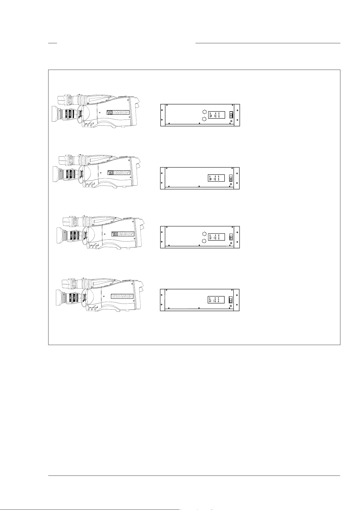
Compatibility with the previous version of the LDK 23
HS is guaranteed, with some limitations of functionality
and performance.
Only the combination of the LDK 23 HS mkII and the
LDK 4058 mkII CPU supports the mkII flicker reduction
system. The mkI Auto Lighting funktion is available if
other combinations are used. The less sophisticated
mkI Auto Lighting funktion is used for adjusting the
video level of the entire image, based on the average
video level of three fields.
0
CABLE TEST
CAM ON
AC
ON AIR
DC
mains
23 HS mkI operation
=
Configurations Operator's Manual LDK 23HS mkII - HS Camera System 3-5
Page 28

Required Software Configurations
Minimum configuration series 9000 parts
System part 12NC software Status software
Camera Head 3922 407 27101 44
CPU LDK4058 3922 407 27121 42
OCP LDK4628 3922 407 12151 78
OCP LDK4629 3922 407 21521 78
MCP1 LDK4607 3922 407 11411 88
3922 407 11421 88
MCP2 LDK4609 3922 407 20901 22
3922 407 20911 22
3-6 Operator's Manual LDK 23HS mkII - HS Camera System Configurations
Page 29

Two-wire Data Control Bus
The two-wire data bus is used to connect all control
units in the Series 9000 control system. The data
cable loops-through from one unit to the other. The
order of connection is not important, however, the total
length of the cables must not exceed 350 metres.
Each unit connected directly to the data bus, either
CPU, camera head or OCP, is identified by a number.
In order to ensure, for example, that OCP 1 controls
the camera connected to CPU 1, the same unique
number must be assigned to both OCP 1 and CPU 1.
The assignment number is set internally on the units
during installation.
The assignment number of a camera head connected
to a CPU is automatically set to the number of the CPU
to which it is connected. The number on the CPU,
which is connected to the data bus, must be set to the
number of the control panel that is to control it.
A camera connected directly to the data bus must
have its assignment number set to the number set on
the OCP that is to control it. It is important to set a
unique number for each CPU/OCP or camera/OCP
group as unpredictable control situations could arise
otherwise.
The MCP is also connected to the data bus, however,
it is not necessary to set an internal assignment
number. The camera or cameras to be controlled are
selected on the MCP front panel itself when operating
the unit.
Note
A maximum of 15 looped-trough standard camera
systems in one chain can be handeld, however, in a
multiple system the load of a LDK 23 HS (mkII) is
twice the load of a standard camera so with level 1
communication software the system can handle a
maximum of 8 LDK23 HS (mkII) camera's.
Other Control Features
Private Data
A private data channel is also available between the
camera and the CPU. This is a two-way serial channel
operating at 2400 B/s with TTL level. This channel can
be used for digital data links (Refer to the Installation
Manual for more detail).
Analogue Ch0-Ch1
Two analogue control channels are available from the
CPU to the camera. These provide a control voltage
from 0V to +5V that can be used for pan control for
example. For more information on these channels
refer to the Installation Manual.
Note
If the analogue Ch1 is used to switch externally the
Aspect Ratio, Ch 1 is not available for analoque
signals from the CPU to the camera.
Configurations Operator's Manual LDK 23HS mkII - HS Camera System 3-7
Page 30

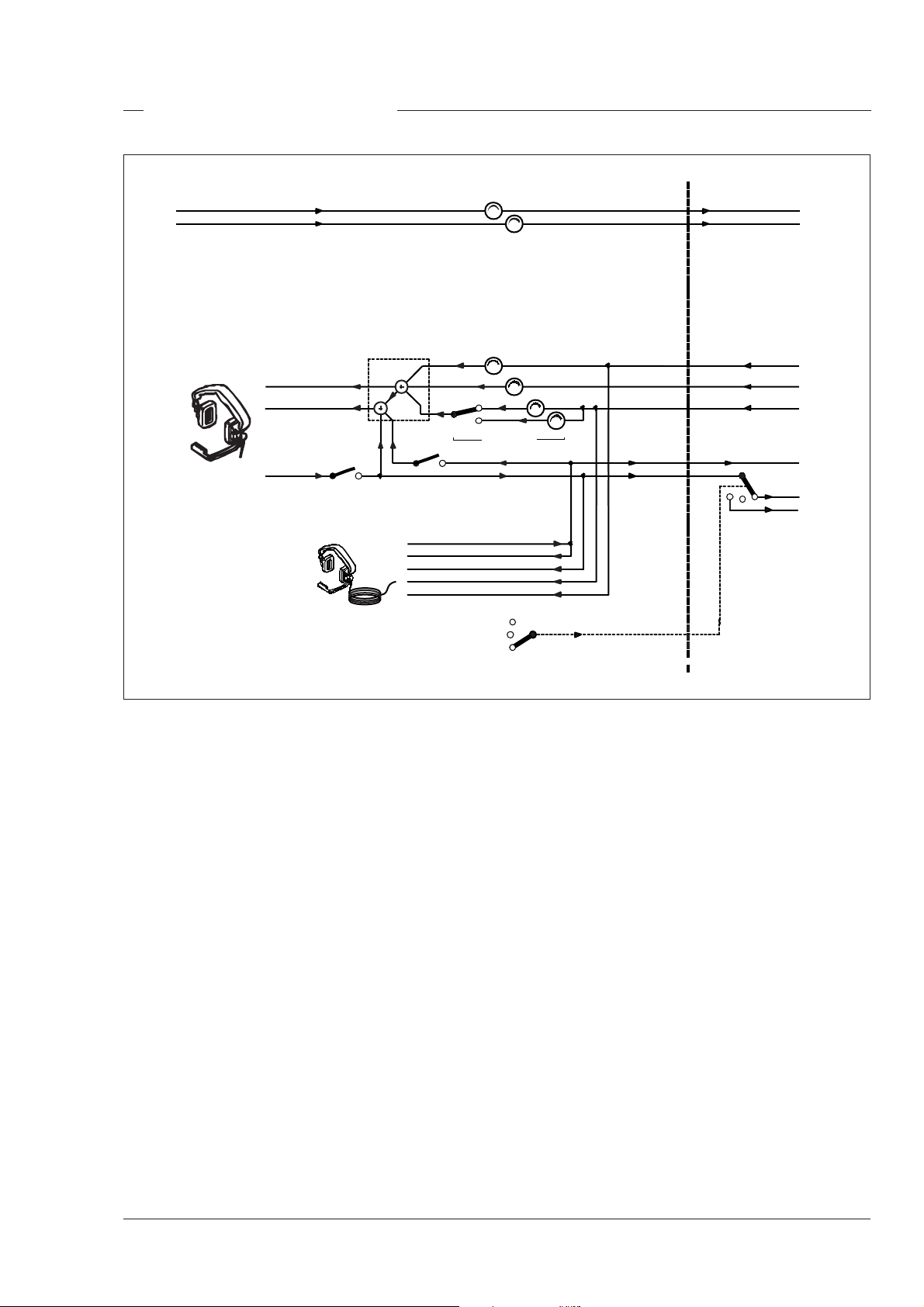
Video Routing
MON VID OUT
INDICA TIONS
VF
VF SIGNAL
SELECTION
or RET button
on the lens
VF
control signal
EXT.VF
control signal
PIP
OFF
control signal
ON
VF- OUT
EXT
LOCAL
control signal
MONITORI NG + VIEWFIN DER
control signal
DIGI TAL VI DEO PROCESSOR
ADC +
Y
Digital
R
Video
G
Decoder
B
EXT1
EXT2
Y
MATRIX
Y
R-Y
B-Y
control signal
TRANSMITTER/
RECEIVER
G
R
B
COMPONENT
EXT SIGNAL
SELECTION
Main video path
When the camera is used in the triax mode, the R, G
and B video signals from the sensors are first subjected
to video processing and then pass to the multiplexer/
transmitter section which sends Y, R-Y and B-Y to the
CPU via the triax cable. The R, G and B video signals
are available for the studio as outputs on the rear of the
CPU.
Viewfinder video
The normal signal displayed in the viewfinder is the Y
signal. This is derived from the R, G and B video
signals from the video processing circuits. Additional
information is added to the viewfinder signal to provide
superimposed text and graphics. The video signal for
display in the viewfinder can be selected from the
above mentioned Y signal or an external 1 or external
2 video signal. The external 1 and 2 video signal are
input from the studio system to the rear of the CPU and
are transmitted via the triax cable to the camera. The
Y, external 1 and external 2 video signals can be
viewed separately, or Y mixed with external 1 or 2.
TRIAX
TRANSMITTER/
RECEIVER
Y
R-Y
B-Y
Output signals
The camera has four video output connectors: two on
its right side and two on the backpanel. The external
output connector carries the external signal from the
CPU. The monitoring out connector carries the signal
which is displayed in the viewfinder.
3-8 Operator's Manual LDK 23HS mkII - HS Camera System Configurations
Page 31
Audio/Intercom Routing
AUDIO CHANNEL 1
AUDIO CHANNEL 2
HEADSET
TEL. RIGHT
TEL. LEFT
CAM MIC
TRACKER
TRACKER MIC
SIDE TONE
CAM MIC
PROD
PROG
AMPLIFICATION
FRONT/REAR
ENG
OFF
PROD
control signal
CPUCAMERA
AUDIO CHANNEL 1
AUDIO CHANNEL 2
TRACKER MIC
PROG
ENG
PROD
PROD
ENG
Audio path
The back panel of the camera has two connectors for
audio microphones. The signals applied to these
connectors are amplified and passed to the multiplexer/
transmitter section of the camera which sends them to
the CPU via the Triax cable. The amplification factor
of the audio microphone signals can be selected via
the control system.
Phantom power is available for the audio microphones.
The default value is +48V (refer to the installation
manual for information on changing this value).
Intercom
Two intercom headsets can be connected to the
camera; one for the cameraman and one for the
tracker.
In the triax mode there are three intercom channels
from the CPU to the camera. These carry the
engineering intercom signal, the production intercom
signal and the programme intercom signal. Two
intercom channels from the camera to the CPU carry
the tracker and cameraman intercom microphone
signals. The latter can be routed in the CPU either to
engineering or to production via the intercom routing
switch on the camera.
The tracker headphone receives the cameraman
microphone signal, the production intercom signal, the
programme intercom signal and either by default the
tracker microphone sidetone signal or the engineering
intercom signal.
The engineering intercom signal, the production
intercom signal and the programme intercom signal
from the CPU are all available for the cameraman
headset. The volume of these signals can be adjusted
and can be switched to either the right or left side of the
headset. The tracker microphone can also be switched
to the left side. The cameraman microphone sidetone
signal is always present on the left side. The volume
of this signal can also be adjusted.
Configurations Operator's Manual LDK 23HS mkII - HS Camera System 3-9
Page 32

3-10 Operator's Manual LDK 23HS mkII - HS Camera System Configurations
Page 33

Section 4
Location of Controls and Functions
This section shows the physical location of the controls and connectors on the camera. These are
grouped according to their function so as to provide a quick reference guide to the operation of a
particular aspect of the camera.
Contents
Power Supply ..................................................... 4-2
Video Functions ................................................. 4-3
Monitoring Functions .......................................... 4-5
Viewfinder .......................................................... 4-7
Viewfinder Indicators .......................................... 4-8
Location of Controls and Functions Operator's Manual LDK 23HS mkII - HS Camera System 4-1
Control Functions ............................................... 4-9
Audio / Intercom .............................................. 4-10
Auxiliary Functions .......................................... 4-12
CPU output Functions ...................................... 4-13
Page 34

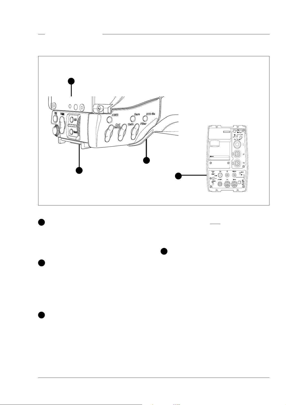
Power Supply
1
3
2
Circuit breaker button (BREAKER)
1
The circuit breaker cuts off the power when excessive
current flows in the camera. Check the units for faults
and if necessary take corrective action before pressing
the circuit breaker button to reset it.
THS 1390
Power switch
2
The power switch has three positions:
Remote : Power is supplied via the Triax cable.
Off : Power to camera is switched off.
Local : Power to camera is switched off.
Note
Local power suppy is not possible with the LDK
23 HS mkII.
Power indicator
3
Power on indication is not available with the LDK
23 HS mkII.
4-2 Operator's Manual LDK 23HS mkII - HS Camera System Location of Controls and Functions
Page 35

Video Functions
SUPER SLO
W MO
TION
LDK23HS
mk II
1
THS 1390
Triaxial cable connector
1
The triaxial cable which connects the camera to the
CPU is connected to this socket. The triax cable
carries all the video and control signals, and the power
supply for the adapter and camera head.
HIGH SPEED
LDK23HS
mk II
SUPER SLO
W MO
TION
THS 1391
3
2
Lens connector
2
The flying lead from the lens is connected to this
socket.
Caution
Do not attach the Viewfinder to the lens
connector (3).
Location of Controls and Functions Operator's Manual LDK 23HS mkII - HS Camera System 4-3
Page 36

1 2 3 4 5
VTR switch
1
The VTR switch is disabled in this mode. In triax mode
however, it will switch the microphone of the headset
to the production intercom channel.
Vertical Shift switch (V-Shift)
2
The V-Shift switch is disabled in this mode.
Clean Scan button (CLS)
3
The camera does not have a ‘clean scan’ facility.
Although it is possible to select a variable exposure
time between 151/181 to 829 Hz, it is not possible to
increase it above the nominal setting (1/150 of 1/180).
Therefore, it is not possible to eliminate the horizontal
bars when shooting monitors with this camera because
their refresh rates are below 150Hz.
Auto White Balance button (AWB)
4
6
7
5
The Bars button is used to switch the colour bar test
signal on and off. (The lens iris closes automatically
when the colour bars are switched on.)
6
This up/down scroll switch allows a choice between
three preset colour temperatures:
• 3200K (3.2K) - for studio lighting conditions
• 5600K (5.6K) - for outdoors, clouded conditions
• 7200K (7.2K) - for outdoors, clear blue skies
and two memory settings AW1 and AW2. These two
memory settings can be filled with measured values
using the AWB button (4).
7
This up/down scroll switch gives a choice between
four gain settings that, except for the 0dB setting, can
be set in the install menu (refer to section 6).
8
Colour Bars button (Bars)
Colour Temperature switch (Col. temp)
Gain switch
THS 1392
The AWB button is a momentary switch, used to start
the automatic white balance process. The camera,
when pointed at a white area in the centre of the
picture, measures and stores a colour temperature
setting in the AW1 or AW2 memory position.
The AWB button only operates if the colour temperature
switch is in the AW1 or AW2 position. Refer to Section
5 for more information on how to use the AWB.
4-4 Operator's Manual LDK 23HS mkII - HS Camera System Location of Controls and Functions
Filter switch
8
When this up/down scroll switch is pressed the filter
wheel moves to its next position. The filter switch has
seven positions:
1 : Clear
2 : ND 0.6 filter
3 : ND 1.2 filter
4 : ND 1.8 filter
5 : 4 Point Star filter
6 : 6 Point Star filter
7 : Cap (lens closed)
Page 37

Monitoring Functions
SUPER SLO
W MO
TION
HIGH SPEED
HIGH SPEED
LDK23HS
mk II
SUPER SLO
W MO
TION
2
Viewfinder connector
1
1
Use this socket to connect the flying lead from the
viewfinder to the camera.
Caution
Do not attach a lens to the Viewfinder
connector 2.
External video output connector
3
This BNC connector carries the external video signal
from the CPU which is selected with the external
signal selection switch 6.
3
THS 1391
4
THS 1390
5
External signal selection switch
5
This switch is used to select the signal displayed in the
viewfinder when the viewfinder signal selection switch
(4) is in the EXT position. The signal displayed for
each position is as follows:
EXT 1 : CPU external input 1.
EXT 2 : CPU external input 2.
MIX 1 : CPU ext. input 1 and cam. Y signal.
MIX 2 : CPU ext. input 2 and cam. Y signal.
Note
Switches (4) and (5) are disabled when a large lens
adapter is used.
Viewfinder signal selection switch
4
This switch is used to choose between the local
camera head signal (Y signal) or an external signal for
display (set with (5) ) in the viewfinder.
Location of Controls and Functions Operator's Manual LDK 23HS mkII - HS Camera System 4-5
Page 38

3
OFF
THS 1393
2
1
4
On-air indicator switch
1
The on-air indicator switch disables (OFF position) or
enables the on-air LED indicator on the viewfinder.
On-air indicators (red)
2
The red on-air LED indicator light to indicate that the
camera is on-air or recording.
On-air / ISO indicators (red / yellow)
3
These LED indicators light red to indicate that the
camera is on-air or recording.
They are also used as ISO-indicators (yellow). This is
a secondary indicator which is controlled by a signal
applied to the signalling connector of the CPU. It
indicates that the camera signal is being used for
recording purposes but is not on-air.
On-air indication will override ISO.
Call switch
4
Operating this momentary switch sends a signal to the
control panels calling for attention.
4-6 Operator's Manual LDK 23HS mkII - HS Camera System Location of Controls and Functions
Page 39
Viewfinder
OFF
THS 1393
1
8
7
2
3
4
6
5
Dioptric adjustment ring
1
Turn this ring to obtain the image that is best suited to
your eyesight.
Crispening switch
2
This switch, when switched on, increases the
sharpness of the picture displayed in the viewfinder.
Zebra switch
3
This switch disables (OFF position) or enables the
zebra pattern in the viewfinder which indicates high
video levels.
Text switch
4
THS 1373
Contrast control
5
Use this rotary control to adjust the contrast of the
viewfinder display to suit your needs.
Brightness control
6
Use this rotary control to adjust the brightness of the
viewfinder display to suit your needs.
On-air indicators
7
The red on-air LED indicators light to indicate that the
camera is on-air or recording. The indicators can be
disabled by switch 8.
On-air indicator switch
8
To prevent the on-screen text from appearing in the
viewfinder set this switch to the OFF position. When
The on-air indicator switch enables and disables the
on-air LED indicators on the viewfinder.
in the OFF position, this switch also disables the
menu selection function of the front rotary switch.
Location of Controls and Functions Operator's Manual LDK 23HS mkII - HS Camera System 4-7
Page 40

Viewfinder Indicators
aspect ratio 4:3
6
7
1
SAVE ME NU BAT T REC TAPE
SAVE ME NU BAT T REC TAPE
SAVE ME NU BAT T RE C TAPE
F3.7
31
31
f00
f00F3.7
ND
ND
ND
RE
RE
RE
2
9
3
4
-+++AW2
-+++AW2AW1
5
Top indicators
1
-+++AW2AW1
BATT Function disabled.
REC This red indicator lights to indicate that the
camera is on-air. It flashes when any
irregularity in the recording system occurs
(function depends on the type of recorder).
TAPE Yellow, when in triax (remote) mode: ISO-
indication.
RE This green indicator lights when the range
extender is selected or toggles when a call
switch is used.
AW1 3,2 5,6
3,2 5,6
3,2 5,6
8
aspect ratio 16:9
SAVE MENU
SAVE MENU
SAVE ME NU BA TT REC T APE ND RE
-+++AW2AW1
-+++AW2AW1
-
Bottom indicators
5
BATT
REC TAPE
BATT
REC TAPE
+
++
AW2
AW1
ND
ND
3,2 5,6
3,2 5,6
3,2 5,6
RE
RE
The following green indicators light when:
- gain is -
+ gain is +
++ gain is ++
AW2 colour temperature stored in memory position
2 is selected
AW1 colour temperature stored in memory position
1 is selected
3,2 colour temperature of 3200 K is selected
5,6 colour temperature of 5600 K is selected
Zoom indication
6
Safe area marker
2
Indicates the degree to which the lens has been
zoomed in or out. This indicator only works when the
Indicates the safe area which represents 80% of the
zoom signal is available from the lens.
whole viewfinder picture area. This is the minimal
area which will be seen on a TV-set.
Centre marker
3
Focus indication
7
Indicates where the lens has been focused. This
indicator only works when the focus signal is available
This cross marks the centre of the picture.
Cadre marker
4
These dotted white lines represent the limits of the
16:9 picture in the 4:3 mode and the limits of the 4:3
picture in the 16:9 mode. The area outside the cadre
will be cut off when the picture is displayed on a
from the lens.
Zebra pattern
8
This diagonal line pattern warns the operator that the
area affected has risen above a predetermined level
of the full scale video exposure value. Level and range
are selectable via the menu control system.
monitor with an other format. The dotted lines can be
switched to a low contrast area, see Installation
Iris indication
9
Manual.
Indicates the diafragm position. This indicator only
works when the iris signal is available from the lens.
4-8 Operator's Manual LDK 23HS mkII - HS Camera System Location of Controls and Functions
Page 41
Control Functions
1
2
THS 1392
3
4
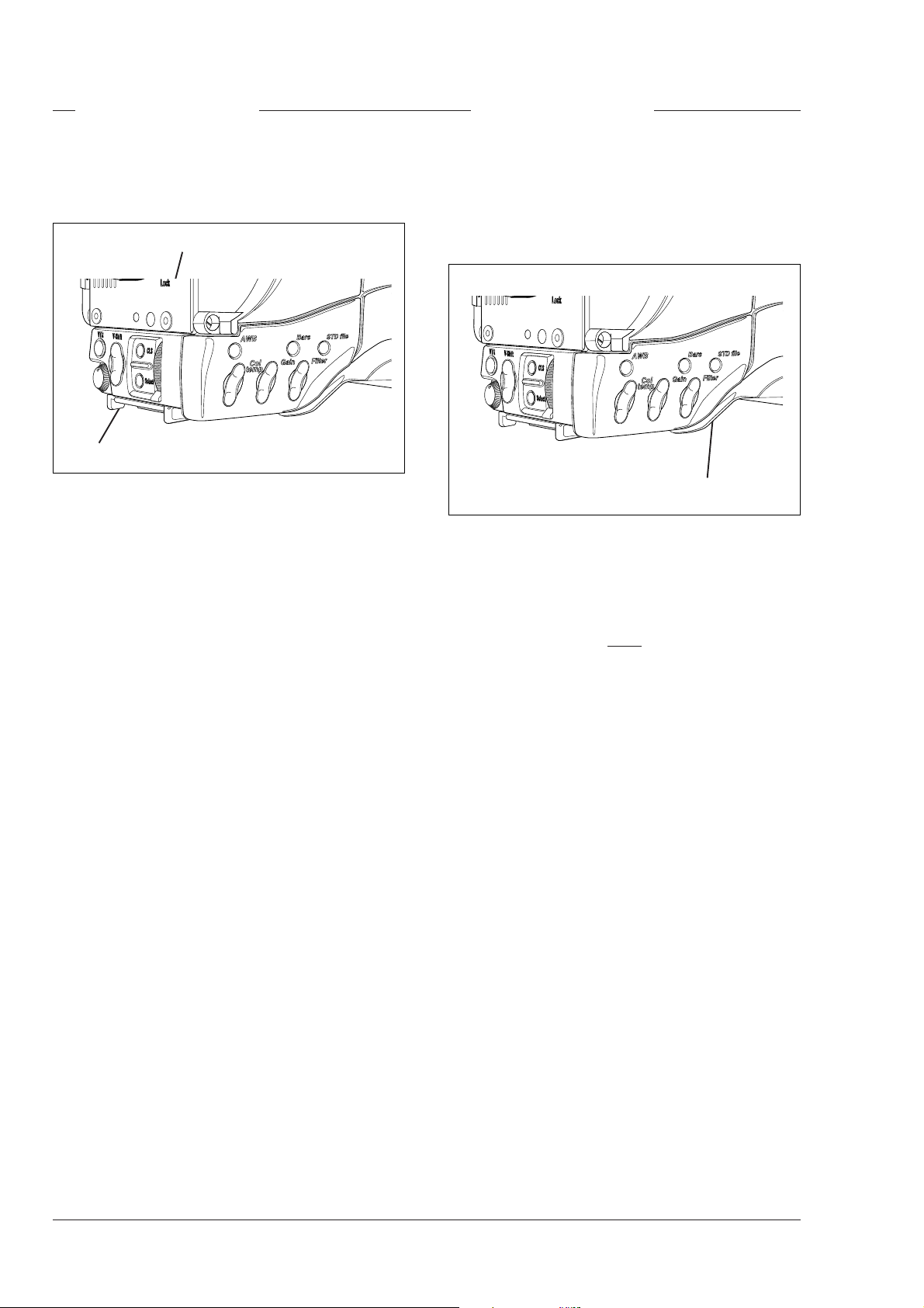
Select switch
1
This switch, when pressed, selects the particular
menu that is pointed out by the cursor in the display or
sets an on/off function.
Rotary control
2
This up/down scroll switch is used to move through the
various menus of the control system or to set a
particular value for a function. The menu selection
function of the switch is disabled when the viewfinder
text is set to OFF.
Standard File button
3
This green button, when pressed and held for 3
seconds, initiates the recall of the standard set-up
parameters (Refer to the appendix). These parameters
only take effect if the camera is not "On Air".
Note
The MCP can select the standard file parameters as
a factory or customer standard file.
Data connector
4
This connector allows the direct connection of the
Operational Control Panel (OCP) or the Master Control
Panel (MCP) from the Series 9000 in order to control
camera functions.
Location of Controls and Functions Operator's Manual LDK 23HS mkII - HS Camera System 4-9
Page 42

Audio / Intercom
1
2
3
4
5
6
7
8
9
4-10 Operator's Manual LDK 23HS mkII - HS Camera System Location of Controls and Functions
Page 43

Intercom routing switch
1
Audio Ch. 2 microphone connector
8
A 3-position switch which routes the cameraman's
intercom microphone signal to engineering (ENG) or
production (PROD), or turns off the intercom.
If the camera is used in triax mode, the momentary
VTR switch at the front of the camera, on the lens or
on a shot box can be used to route the cameraman's
intercom microphone signal to production regardless
of the position of this switch.
Headset Programme volume control
2
This control varies the volume of the programme
intercom signal to the cameraman's headset.
Headset Engineering volume control
3
This control varies the volume of the engineering
intercom signal to the cameraman's headset.
Headset Production volume control
4
Balanced input for high quality microphone. A phantom
power supply (48V) can be internally selected (see
installation manual). The gain of this audio channel
can be controlled from the CPU.
Headphone volume
9
This control varies the volume of the production
intercom signal to the cameraman's headset when
the selection switch (5) is in the FRONT position.
This control varies the volume of the production
intercom signal to the cameraman's headset when
the selection switch (5) is not in the FRONT position.
Production volume control selection
5
A 2-position switch for the production intercom which
selects control of the volume at the front of the
camera (9) or control of the volume at the rear (4).
Cameraman intercom connector
6
Headsets with dynamic or carbon type microphones
can be connected to this socket (see installation
manual).
Audio Ch. 1 microphone connector
7
Balanced input for high quality microphone. A phantom
power supply (48V) can be internally selected (see
installation manual). The gain of this audio channel
can be controlled from the CPU.
Location of Controls and Functions Operator's Manual LDK 23HS mkII - HS Camera System 4-11
Page 44

Auxiliary Functions
1
2
3 4
Teleprompter output connector
1
This BNC connector is disabled in this mode.
Script Light connector
2
A 3-pole socket which supplies +12 Vdc for a script
light (maximum dissipation 3W). Scriptboard
LDK 6985/15 is connected to this socket.
Auxiliary connector
3
This 11-pole female socket provides analogue control
signals and facilities for the connection of a private
data channel (see installation manual).
Tracker connector
4
This 11-pole female socket provides full intercom and
signalling facilities for the dolly or crane driver (see
installation manual).
4-12 Operator's Manual LDK 23HS mkII - HS Camera System Location of Controls and Functions
Page 45

CPU output Functions
Triple scan Serial Digital video outputs
1
1
PH2
DSC
DSC
1
PH1
HS
PH3
DSC
1
2
The PH1, PH2 and PH3 BNC connectors provide
combined a triple scan serial digital video signal to
the Multi Channel disk recorder for Super Live
Slow Motion. (Consult the Installation Manual of
your disk recorder as required for detailed
information).
Normal Scan Serial Digital video outputs
2
The three DSC BNC connectors provide a normal
scan serial digital video output.
Location of Controls and Functions Operator's Manual LDK 23HS mkII - HS Camera System 4-13
Page 46

4-14 Operator's Manual LDK 23HS mkII - HS Camera System Location of Controls and Functions
Page 47

Section 5
Shooting
This section contains information on the practical use of the camera using the viewfinder display
and the switches at the front to control the camera system.
Contents
Using the Camera .............................................. 5-2
Standard settings ............................................... 5-2
Colour Bar .......................................................... 5-3
Gain selection .................................................... 5-3
Optical filter selection ........................................ 5-4
Shooting Operator's Manual LDK 23HS mkII - HS Camera System 5-1
Colour temperature selection .............................. 5-4
Auto-White Balance ........................................... 5-5
Clean Scan ........................................................ 5-5
Artificial light conditions ..................................... 5-6
Page 48
Operator's Manual LDK 23HS mkII - High Speed Camera System
Using the Camera Standard settings
This section describes the operational functions that
are directly available, via the viewfinder display and
the switches at the front and front-left.
System Menu Rotary control
System Menu Select button
The rotary control and select button at the front of the
camera offer a convenient way of accessing the menu
system which provides full control of the camera. But
there are a number of steps that must be carried out
before satisfactory shot can be obtained:
a. The camera must be set up and powered.
b. The standard settings must be recalled.
c. Adjustments must be made for ambient lighting.
d. Shots of TVs or monitors must have special
consideration.
e. In Artificial light conditions use preset lighting
settings to ensure a slow motion picture without
pulsing light effects.
To ensure that some of the camera functions are not
set to unusual values a standard file has been defined
in the factory which contains the normal values for
most functions. The table in the appendix lists the
values that are set when the standard file is recalled.
Standard file button
Press the green STD File button on the left side panel
of the camera and hold it for 3 seconds to recall the
standard values for the various functions. The standard
values only take effect when the camera is not On Air.
Note
The MCP can be used to set the standard scene
file to either the factory standard or a customer
defined standard.
Physical set-up and power supply
Attach lens, viewfinder and microphone to the camera
as described in 'Assembling the Units' in Section 2. If
required mount the camera on a tripod.
For remote operation connect the triax cable to the
triax connector and the camera operator's headset to
the headset socket on the rear panel of the camera.
Connect the audio microphone to either the audio 1 or
2 socket on the rear panel of the camera. For remote
operation the camera is powered by the CPU via the
triax cable. Set the power switch on the rear of the
camera to the position REMOTE.
The camera is now ready for use, however, the
ambient conditions must now be taken into account
and the appropriate adjustments make.
5-2 Operator's Manual LDK 23HS mkII - HS Camera System Shooting
Page 49

Colour Bar
Colour bar switch
The front/left side panel also contains a button for
switching on the colour bar test signal. The colour bar
is a standard test signal which is used to set up and
check the camera before use.
When the colour bar is selected the following functions
are temporarily set to the values listed below:
Black stretch : Off
White limiter : Off
Zebra : Off
Safe area (VF) : Off
Cadre (VF) : Off
Filter wheel : Cap
Gain selection
Depending on the available light levels it may be
necessary to adjust the gain of the camera.
Gain up/down selection switch
The gain is selected via the Gain up/down switch on
the front/left side panel. When this switch is pressed
initially, a list of the available values for the gain is
displayed in the viewfinder. The cursor marks the
current value. A new value is chosen by scrolling up
or down through the available values. The viewfinder
display is as follows:
12
6
Gain dB
0
-3
111 2-4
The selection is made when the cursor is moved to a
new value. The display disappears 1 second after the
release of the button.
Shooting Operator's Manual LDK 23HS mkII - HS Camera System 5-3
Page 50
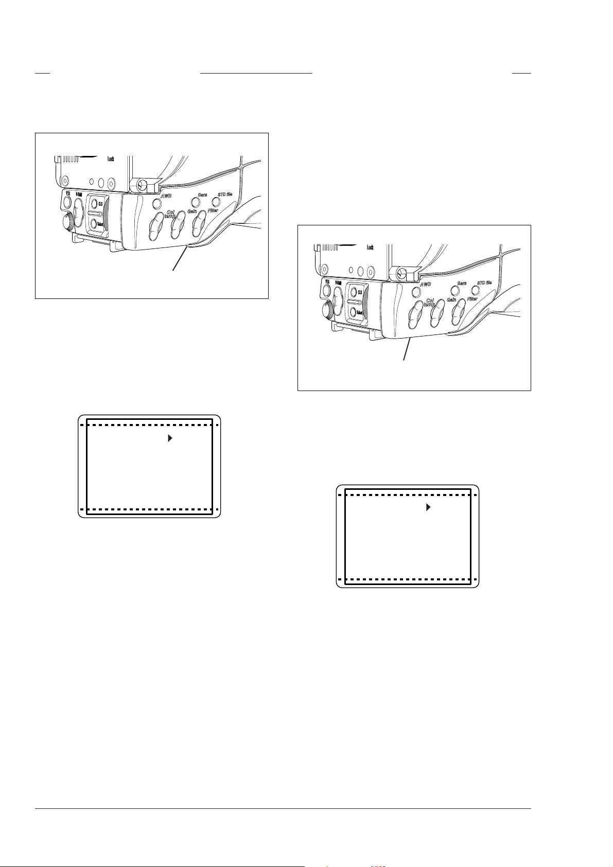
Optical filter selection
Colour temperature selection
A filter can be placed in the path of the optical signal
to restrict the incoming light or for artistic effect.
Optical filter up/down selection switch
The filter is selected via the Filter up/down switch on
the front/left side panel. When this switch is pressed
initially, a list of the available positions of the filter
wheel is displayed in the viewfinder. The cursor marks
the current value. A new position can be chosen by
scrolling up or down through the available choices.
The viewfinder display is as follows:
For true colour reproduction the ambient lighting
conditions must be compensated for by selecting a
value for the colour temperature. The standard file
setting is 3200K (normally used for tungsten light).
Two other reference colour temperatures are available;
5600K (for outdoors, clouded conditions) and 7500K
(for outdoors, clear blue skies). Two similar memory
positions (AW1 and AW2) are available to store the
results of the auto-white measurement process.
Colour temperature up/down selection switch
Clr
2
Filter
3
4
5
331 1-7
The selection is made instantaneously when the
cursor is moved. The display disappears after 1
second when the button is released. There are more
choices available than are visible in the display. Scroll
up or down to see all the options. The standard
position is clear (CLR).
The colour temperature is selected via the Col. Temp.
The colour temperature is selected via the Col. Temp.
up/down switch on the front/left side panel. When this
up/down switch on the front/left side panel. When this
switch is pressed initially, a list of the five values is
switch is pressed initially, a list of the five values is
displayed in the viewfinder. The viewfinder display is
displayed in the viewfinder. The viewfinder display is
as follows:
as follows:
3k2
5k6
Ctemp
7k5
aw1
aw2
112 1-5
The cursor marks the current value. A new value is
chosen by scrolling up or down through the available
values. The selection is made when the arrow is
moved. The display disappears after 1 second when
the button is released.
5-4 Operator's Manual LDK 23HS mkII - HS Camera System Shooting
Page 51

Auto-White Balance
Clean Scan
If the three preset colour temperatures do not match
your lighting conditions then the auto-white procedure
must be carried out as follows:
Automatic white balance button
Colour temperature up/down selection switch
a. First select one of the memory positions AW1 or
AW2 in which to store the measured colour
temperature value with the colour temperature up/
down switch.
b. Press the AWB button on the front/left side of the
camera to start the automatic white balance
procedure. The autowhite window appears in the
viewfinder.
The camera does not have a ‘clean scan’ facility.
Although it is possible to select a variable exposure
time between 151/181 to 829 Hz, it is not possible to
increase it above the nominal setting (1/150 of 1/180).
Therefore, it is not possible to eliminate the horizontal
bars when shooting monitors with this camera because
their refresh rates are below 150Hz.
Autowh Win
c. Point the camera to fill the window with a reference
white object.
d. Press the AWB button again to start the actual
automatic white balance measurement procedure.
The Autowh indicator in the viewfinder is now On.
e. When the process is completed (within a few
seconds) the Autowh indicator in the viewfinder
changes to Off. The measured colour temperature
is now stored in the selected memory position and
can be recalled as required. The camera is now
ready for use.
Note
Iris is set to 90% during the auto-white process
and knee is turned off automatically.
Shooting Operator's Manual LDK 23HS mkII - HS Camera System 5-5
Page 52
Artificial light conditions
In artificial light conditions it is recomended to examine
the lighting conditions.
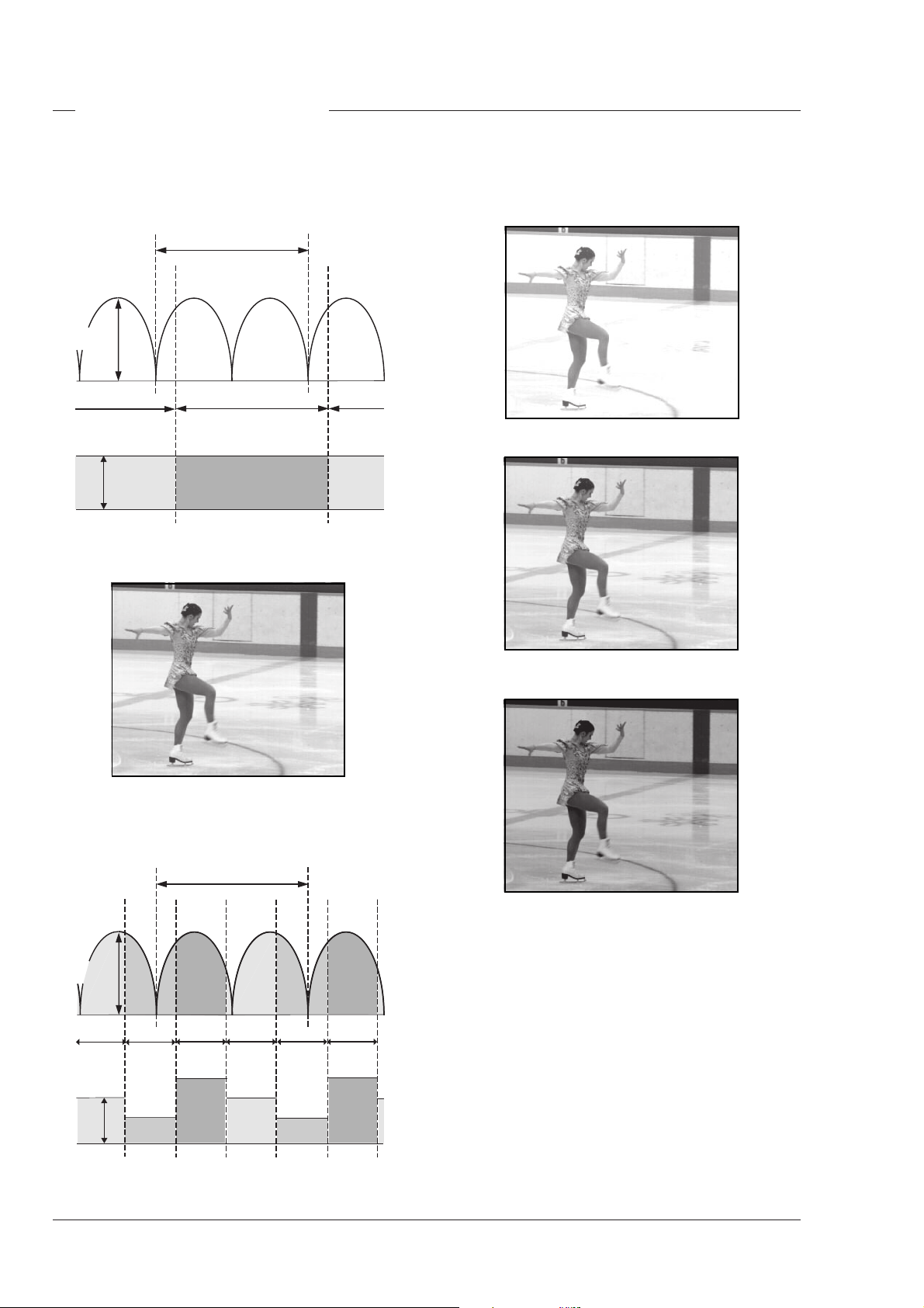
Standard Camera
1 Period
Light
Amplitude
1 Field
Video
Level
The exposure time of a standard camera corresponds
with twice the lighting period.
The exposure time of a Triple Scan high speed
camera is a third of the exposure time of a standard
camera.
Field 1
Although the Licht is alternating each field has the
same video level.
Triple Scan Mode
1 Period
Light
Amplitude
Field 2
Video
Level
Field 2
Field 3Field 1Field 3
Field 1
Field 2
Field 3
The alternating light amplitude causes different video
levels for the three fields. This effect is only visible
during slow motion replay. The field flickering will not
appear in the Normal Scan output. The LDK 23HS
mkII uses various preset settings to accommodate
various artificial lighting conditions.
5-6 Operator's Manual LDK 23HS mkII - HS Camera System Shooting
Page 53

Presets for artificial lighting conditions
The alternating light amplitude may cause flickering in
at the Triple Scan output. There are 5 presets to
accommodate different artificial lighting conditions.
There are two ways to set the lighting presets; The
camera systems menu and the MCP (Master Control
Panel). The camera systems submenu Install \ Lighting
contains the item Advanced. Set the Advanced item
to the required preset to accommodate the artificial
lighting condition. The MCP (Master Control Panel)
gives access to the preset settings. Consult the
Operator's Manual of your MCP as required for detailed
information how to set these presets.
Use the 5 presets are tuning the high speed camera
to accommodate 5 gradations of lighting conditions as
follows:
Optimal
Optimal (Opt) is the default preset. This preset is used
in daylight and in non-alternating or high-frequency
artificial lighted environments. Each field has the
same video level and Flicker reduction is not
necessarily.
Extreme
This preset (Ext) results in a 100% flicker free picture
with an increased amount of motion blur. Use only this
setting in lighting conditions with extreme light
amplitudes. This preset activates a flicker reduction
technique different from technique used in the Good,
Fair and Poor presets. It's drawback is that is has an
increased amount of motion blur.
Note
For fundamental reasons, it is not recommended
that a PAL camera (50Hz) is used in conjunction
with 60Hz lighting. Similarly, it is not recommended
that an NTSC camera (60Hz) is used in conjunction
with 50Hz lighting.
Good
Use the Good (Goo) preset in artificial lighting
conditions with minor amplitude changes. Examples
are enviroments lighted with incandescent or wellbalanced 3-phase light. Use also this preset in daylight
if aditional artificial light with an alternating effect is
used.
Fair
The Fair (Fai) preset is used in artificial light conditions
with significant light amplitude changes. For example,
fluorescent lighted enviroments.
Poor
This preset (Poo) is used with artificial light, which has
a major light amplitude change. Examples are
enviroments lighted with HMI, MHD, gas discharge
lamps or neon light.
Switching to the Poor preset results in a almost flicker
free picture. In most cases this will be the preset to
start with if flicker is visable in the Optimal preset.
Fine- tune the light accommodation by switching to
the Poor or Fair presets if other artifacts become
noticeable.
Shooting Operator's Manual LDK 23HS mkII - HS Camera System 5-7
Page 54

5-8 Operator's Manual LDK 23HS mkII - HS Camera System Shooting
Page 55

Section 6
Operating the Menu System
Because the LDK 23HS mkII offers such a wide range of functions, this section describes the
structure of the control system. It contains procedures for controlling the menu system and explains
how to program the menu system for your personal preferences. The menu structure and the
methods of function selection are also explained.
Contents
Introduction ........................................................ 6-2 Systems Menu................................................... 6-3
Operating the Menu System Operator's Manual LDK 23HS mkII - HS Camera System 6-1
Page 56

Introduction
Operationally, the camera is very easy to use.
However, because of the large number of functions
available and the large number of set-up options, it
may require some time for you to become familiar with
them all. We recommend that you spend time using
the various controls and displays in order to discover
the wide range of possibilities.
Read the instructions in this section carefully but also
feel free to examine the various menus in detail. In this
way you will learn quickly to intuitively operate the
camera.
6-2 Operator's Manual LDK 23HS mkII - HS Camera System Operating the Menu System
Page 57

Systems Menu
The system functions of the camera are grouped into
menus and sub-menus.
System Menu Rotary control
System Menu Select button
The systems menu is viewed in the viewfinder and
navigated by means of the Rotary control and the
Select button which are both located at the front of the
camera.
Entering the Systems menu
When you first enter a menu (other than the MAIN
menu) the cursor is positioned next to the first item.
The TOP and PREVIOUS entries are not immediately
visible but are located above the first item. Use the
Rotary control to scroll up to them.
- Select TOP to bring you back to the MAIN menu.
- Select PREVIOUS to go back to the menu that you
were in before the current one.
To p > >
Previous >>
Gain >>
Black >>
Contour >>
Sensor >>
Iris >>
Press the Select button after the camera is switched
on. The MAIN menu screen shows five items. One
more item is hidden but becomes visible when you
scroll down using the rotary control. (Some of these
items may not appear if the user level is not set to 4.)
Operate >>
Setup >>
VF/Lens >>
Install >>
Files >>
0 1-6
Diagnostic >>
A cursor shows your position in the menu. The Rotary
control moves the cursor up and down.
Finding your way
Use the Rotary control to move the cursor through the
menu items. If a double arrow (>>) is visible, then
pressing the Select button brings you one level lower
in the menu system. Only five items are visible in each
menu. Scroll up or down to see any additional items.
1 3-11
Audio >>
Test >>
Knee >>
Matrix >>
The Operate menu above shows the items displayed
when you first enter the menu and the other items that
are available by scrolling up or down with the Rotary
control.
Leaving the Systems Menu
If you do not use the menu it disappears after a few
seconds. (This delay can be set at the VF / Txt Time
item in the Install menu.) However, when you press
the Select button again you enter the System menu at
the last position of the cursor and not at the top of
MAIN menu. Set the menu item at the VF / Txt Time
item in the Install menu to On and the menu will not
time out. Set this item back to Tim to let the menu
disapear after time out.
To prevent confusion the next time you enter the
System menu, it is advisable to leave the System
menu by returning to the MAIN menu (TOP).
Operating the Menu System Operator's Manual LDK 23HS mkII - HS Camera System 6-3
Page 58

Making changes
Menu numbers
To find out where you have to go to change a function,
consult the appendix to discover under which menu
group or subgroup the function you want to change is
located.
If the cursor points to an item (and there are no double
arrows to indicate a sub-menu) then the item pointed
to has a value. The value can be:
- a toggle value (only two values)
- a list value (more than two values)
- an analogue value (variable from 00 to 99)
or unavailable (---).
If the value is unavailable it cannot be changed. This
is indicated by three dashes (---). This can occur, for
example, when a function is switched off. The analogue
values associated with that function are then
unavailable.
If there are only two values associated with the
function, then pressing the Select button toggles
between these two values.
If a value is displayed next to a function that is one of
several possible values, then pressing the Select
button places the cursor in a list menu indicating the
value currently selected. Use the Rotary control to
point to a new value. Press the Select button to return
the cursor to the function list.
If an analogue value is displayed next to a function
name, then pressing the Select button places the
cursor in front of the value and the Rotary control is
used to change the analogue value. Press the Select
button to return the cursor to the function list.
Undoing changes
The main menus are numbered from 1 to 6. Each
main function under the main menu is given a second
digit (for example, the Gain under the Operate menu
is given number 11, the Black function 12). In some
cases a third level number is given. For example, the
skin function of the contour function of the Setup
menu has number 256.
The first digit refers to the main menu
1 for Operate
2 for Setup
3 for VF/Lens
4 for Install
5 for Files
6 for Diagnostics
The second digit refers to the function under the main
menu. A third digit, if present, refers to the subfunction. This numbering system is used to assign
particular functions to the programmable user switches
when they are being customized.
The menu number appears under and to the left of the
menu display.
Note
Do not confuse the menu number with the line
numbers. Because of the TOP and PREVIOUS
menu items, the menu numbers are 2 less than the
line numbers. This is not the case for the Main
menus as there are no TOP and PREVIOUS items
available in the TOP menu itself. The TOP menu
shows five main menu items initially. If you scroll
through the display, one additional menus appears.
To see how many lines a menu has, look at the
number under and to the right of the menu. This
number, for example, 1-7 indicates that the cursor
is at line 1 and that there are 7 lines altogether.
If you make changes to the video settings in the
Menu logic
Systems menu and you decide not to keep them, use
the Std. File button at the side of the camera to recall
a standard set of values for the video parameters.
Operate menu
This menu contains the functions which are normally
used during the operation of the camera.
Menu Structure
Setup menu
There is one top menu which contains six main
menus. The numbering scheme and the reasons for
grouping the functions under these heading is
explained below. For a full list of menu functions refer
to the table in the appendix.
6-4 Operator's Manual LDK 23HS mkII - HS Camera System Operating the Menu System
The setup menu contains those functions which are
initialized before starting shooting. In many cases
these are the individual (R, G and B) analogue setup
parameters of functions which are switched in the
operate menu.
Page 59

VF/Lens menu
As the name indicates, the functions contained under
this menu control various aspects of the viewfinder
and the lens.
Gain
The gain can be selected in four steps: -, 0, + and ++.
The actual value of the gain in dB can be assigned to
these symbols. This is done in the Install menu.
Install menu
This menu contains functions which are used to install
the camera into a particular configuration. It also
contains controls which can be used to customize the
LCD and viewfinder displays and to assign particular
switches on the camera according to your preferences.
Files menu
This menu allows function values to be stored in
scene files and recalled as required.
Diagnostic menu
The diagnostic menu is designed to provide information
on the current status of the camera.
Menu Install Features
User level
The user level function in the Install menu determines
what is displayed in the menus. For example, for user
level 4, the Top menu contains 6 Main menus.
However, for user level 1 the Top menu only shows
the VF/Lens and Install menus.
The purpose of the four user levels is to restrict the set
of functions which can be changed by whoever is
using the camera. In this way a more centralized and
uniform control can be achieved and the danger of the
camera operator accidentally changing critical
functions while shooting is reduced.
The "-" can be set to -6dB or -3dB.
The '0' is always 0dB.
The '+' can be set in steps of 3dB between 0dB and the
value of '++'.
The '++' can also be set in steps of 3dB between the
value of '+' and 30dB.
Note
The '+' and '++' steps can not have the same value.
Files
The files menu enables four different scene files to be
stored and recalled. If the message NOK is displayed
then the old values are restored. If the camera is
on-air when a scene file is recalled then the recalled
values do not become active until the camera switches
off-air.
The division of the levels was decided using the
following criteria:
1. Video related functions blocked.
2. All video related functions that can be checked on
a black & white monitor can be controlled.
3. All video related functions that can be checked on
a colour monitor can be controlled.
4. All functions can be controlled.
The maximum user level set on the MCP, restricts the
number of user levels available on the camera.
Operating the Menu System Operator's Manual LDK 23HS mkII - HS Camera System 6-5
Page 60

6-6 Operator's Manual LDK 23HS mkII - HS Camera System Operating the Menu System
Page 61

Appendix
Contents
Menu Structure ................................................. A-3
Operate Menu ................................................ A-3
Setup Menu ................................................... A-4
VF/Lens Menu ............................................... A-6
Appendix Operator's Manual LDK 23HS mkII - HS Camera System A-1
Install Menu................................................... A-7
Diagnostic Menu ............................................ A-8
Files Menu .................................................... A-8
List of Menu Functions...................................... A-9
Page 62

The appendix contains two tables listing the contents
of the menu system.
The first table presents the functions ordered in the
logical divisions of the menu system itself. The table
is colour coded to represent the functions that are
available with different user levels. All available choices
are listed for a function. The default (Def) column lists
the values of the functions when a camera is delivered.
If the requirements listed in the column 'Available if...'
are not met, the value of the particular function will be
displayed as a triple dash (---) or a value can not be set.
The second table contains an alphabetical list of the
menu functions. This table is used to find the menu
number of a function to assist in navigating to that
function.
A-2 Operator's Manual LDK 23HS mkII - HS Camera System Appendix
Page 63

Menu Structure
)
)
)
Menu UL
Operate
Gain 2 >>
Gain dB 2
Ctemp 2 3k2,5k6,7k5,aw1,aw2 3k2 Colour temperature
Autowh 2 Off,Win,On,Fai Off Ctemp aw1,aw2
Black 2 >>
MBlack 2 00 to 99 50 Master black
Blackstr 2 On,Off Off Colourbar Off Black stretch switch
level 2 00 to 99 50 Blackstr On Black stretch level
Contour 2 >>
Contour 2 On,Off On Contour switch
Contour Src
Contour Lev.
V-cont 2 00 to 99 50 Contour On Vertical contour level
Noise sl 2 00 to 99 05 Contour On Noise slicer level
Softcont 2 On,Off On Contour On Soft contour switch
Soft lev 3 00 to 99 70 Softcont On Soft contour level
Sensor 2
Shutter 2
Exp.time 2
Exp. Var 2
Asp Ratio 2
Asp Ratio
input 2
select 2
Iris 2
Auto Iris 2
Audio 2
Audio1 2
Audio2 2
Test 2
Cbar 2
Sawt 2
Knee 2
Matrix 2 1, 2 2 Matrix switch
Available Choices Def Available if ... Explanation
2>>
-6,-3,0,3,6,9,12,15,18,21,24,27,30
2 R,G,Y,R+G Y Contour source
2 00 to 99 50 Contour On Contour level
>>
>>
Nom,200,500,1k,Var
151 to 829 151 Exp Time Var Clean scan in Hz
>>
2
Loc,Ext Loc
4:3,169 4:3 input is Loc Aspect ratio switch
>>
On,Off On Automatic Iris switch
>>
-22,-28,-34,-40,-46,-52,-58,-64 -64 Triax mode Audio 1 level select
-22,-28,-34,-40,-46,-52,-58,-64 -64 Triax mode Audio 2 level select
>>
On,Off Off Colour bar switch 2)
On,Off Off Sawtooth switch 3)
Off,Aut,Var Var Knee switch
0 Gain presets Gain switch -see the Install menu for values
Automatic white balance; Off when ready 1)
Nom
Exposure time switch
Aspect ratio switch source (Ext= Analogue Ch1)
1
Autowh temporarily switches Knee to Off and Iris to approx. 80%
2
Cbar temporarily switches to Off: Blackstr, Wh.Limit, Zebra, Cent crs, Save ar, Cadre
3
Sawt temporarily switches to Off: Shading, Flare, Cent crs, Save ar, Cadre and Filter to Cap
Appendix Operator's Manual LDK 23HS mkII - HS Camera System A-3
Page 64
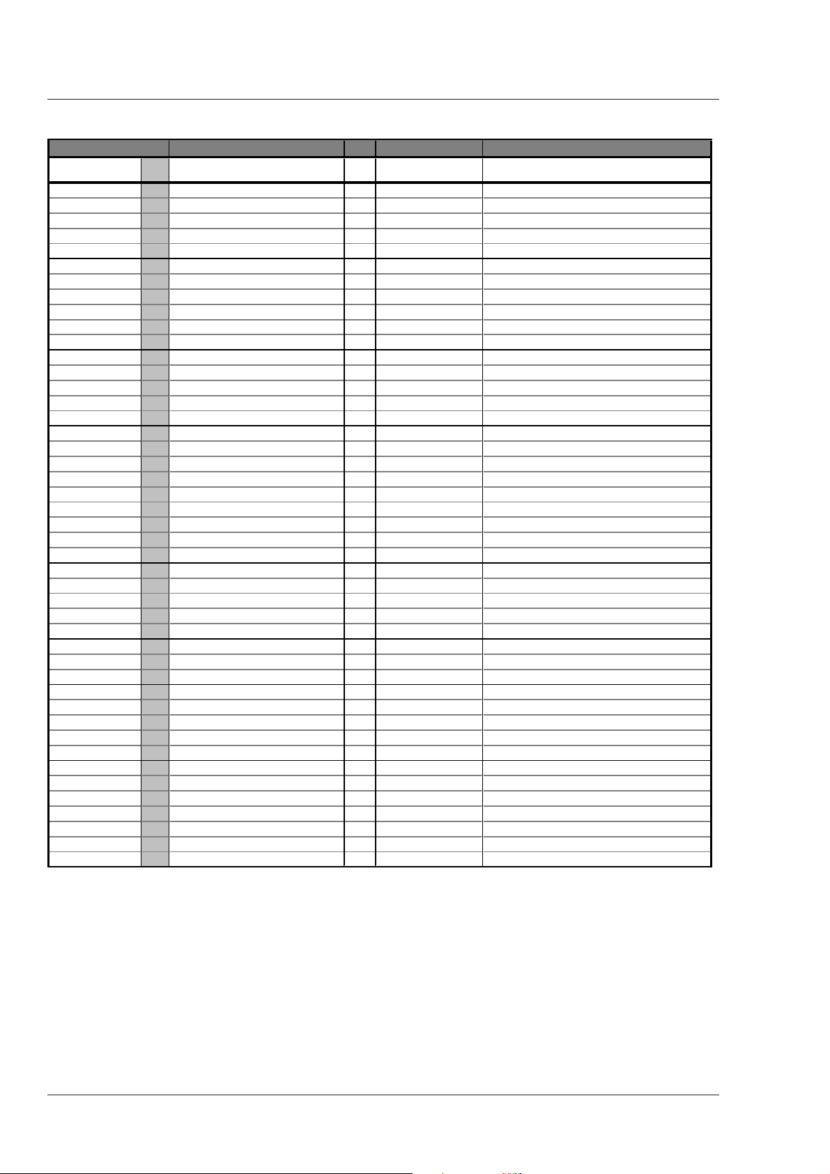
Menu UL Available Choices Def Available if ... Explanation
Setup(1)
Gain 2 >>
Gain dB 2
Red 3 00-99 50 Red gain (limited to colour temp setting)
Green 3 00-99 50 Green gain (limited to colour temp setting)
Blue 3 00-99 50 Blue gain (limited to colour temp setting)
Black 2 >>
Black 2 function identification text
Auto 2 On,Off Off Automatic black level
Red 3 00-99 50 Red black level
Green 3 00-99 50 Green black level
Blue 3 00-99 50 Blue black level
Gamma 2 >>
Gamma 2 Lin,1,2,Var 1 Gamma switch
Red 4 00-99 76 Gamma Var Red gamma level
Master 2 00-99 76 Gamma Var Master gamma level
Blue 4 00-99 76 Gamma Var Blue gamma level
Knee 2 >>
Knee 2 Off,Aut,Var Var Knee switch
Slope R 4 00-99 50 Knee is Var Red knee slope
Slope M 3 00-99 00 Knee is Var Master knee slope
Slope B 4 00-99 50 Knee is Var Blue knee slope
Point R 4 00-99 50 Knee is Var Red knee point
Point M 3 00-99 10 Knee is Var Master knee point
Point B 4 00-99 50 Blue knee point
Limit 4 00-99 - Knee is Var Knee limit level
Contour 2 >>
Contour 3 Off,On On Contour switch
Cont Src 3 R,G,Y,R+G Y Contour source
Lev.dep 3 00-99 50 Contour On Contour level dependence
Co / Fine 3 00-99 25 Contour On Contour coarse / fine level
Wh. Limit 4 >>
Wh. Limit 4 On,Off On White limiter switch
Master 4 00-99 60 Wh. Limit On White limiter master level
Flare 2 >>
Flare 2 On,Off On Sawtooth Off Flare switch
Red 4 00-99 15 Flare On Red flare level
Green 4 00-99 15 Flare On Green flare level
Blue 4 00-99 15 Flare On Blue flare level
Intercom 2 >>
Cam.mic 2 On,Off Off Cam mic switch
Tr.mic 2 On,Off On Tracker mic switch
Cam prod 2 Off,L,R,L+R L+R Cam headphone prod switch
Cam prog 2 Off,L,R,L+R L+R Cam headphone prog switch
Cam eng 2 Off,L,R,L+R L+R Cam headphone eng switch
Sidetone 2 00-99 50 Audio lf present Cam headphone side tone level
2>>
-6,-3,0,3,6,9,12,15,18,21,24,27,30
0 Gain presets
Gain switch -see the Install menu for values
A-4 Operator's Manual LDK 23HS mkII - HS Camera System Appendix
Page 65

Menu UL Available Choices Def Available if ... Explanation
R
Setup(2)
Shading 4 >>
Shading 4 On,Off On White shading switch
Shad R 4 >>
H saw R 4 00-99 50 Shading On Horizontal saw Red
H par R 4 00-99 0 Shading On Horizontal par Red
V saw R 4 00-99 50 Shading On Vertical saw Red
V par R 4 00-99 0 Shading On Vertical par Red
RE saw
Shad G 4 >>
H saw G 4 00-99 50 Shading On Horizontal saw Green
H par G 4 00-99 0 Shading On Horizontal par Green
V saw G 4 00-99 50 Shading On Vertical saw Green
V par G 4 00-99 0 Shading On Vertical par Green
RE saw G 4 00-99 0 RE & Shading On Range Extender Offset Green
Shad B 4 >>
H saw B 4 00-99 50 Shading On Horizontal saw Blue
H par B 4 00-99 0 Shading On Horizontal par Blue
V saw B 4 00-99 50 Shading On Vertical saw Blue
V par B 4 00-99 0 Shading On Vertical par Blue
RE saw B 4 00-99 0 RE & Shading On Range Extender Offset Blue
2>>
4 00-99 0 RE & Shading On Range Extender Offset Red
Appendix Operator's Manual LDK 23HS mkII - HS Camera System A-5
Page 66
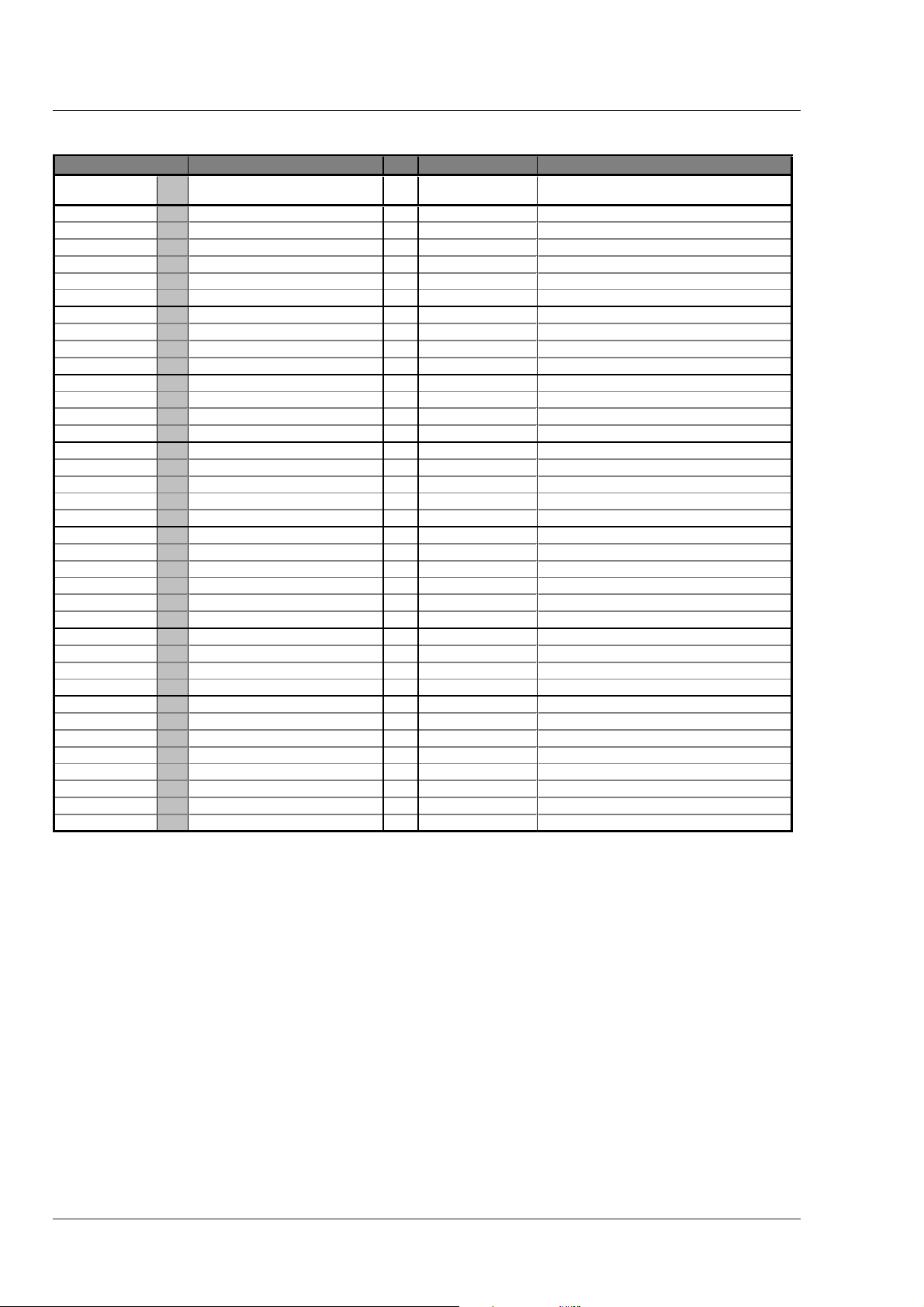
Menu UL Available Choices Def Available if ... Explanation
d
Vf/Lens
Vf Inst 0-1 >>
Vf mon 0-1 Y,R,G,B Y Viewfinder monitor select
Vf Ext 0-1 Ex1,Ex2,YE1,YE2 Ex1 Viewfinder external select
Vf Cont 0-1 >>
Vf Cont 0-1 On,Off,Bst On Viewfinder contour select
Level 0-1 00-99 50 Cont Sel On,Bst Viewfinder contour level
Zebra 0-1 >>
Zebra 0-1 On,Off,Win Off Viewfinder zebra switch
level 3 00-99 50 Zebra is On, Win Viewfinder zebra level
contr 3 00-99 50 Zebra is On, Win Viewfinder zebra contrast
Indicat. 0-1 >>
Zoom Ind 0-1 On,Off Off LLA present Zoom level visible in VF
Iris Ind 0-1 On,Off Off Iris follow level visible in VF
Focus In
Markers 0-1 >>
Wh. Ind 0-1 00-99 50 Viewfinder marker white level
C cross 0-1 On,Off On Centre cross switch
Safe Ar 0-1 On,Off On Colourbar off Safe area switch
Cadre 0-1 On,Off On Sawtooth off Cadre switch
PIP 0-1 >>
PIP 0-1 On,Off Off PIP On/Off switch
Location 0-1 1,2,3,4 1 PIP On Location of PIP
Reverse 0-1 On,Off Off PIP On PIP Reverse mode
Size 0-1 S,L S PIP On PIP Size (Small or Large)
Border 0-1 On,Off Off PIP On Border around PIP
Iris 3 >>
Iris 3 function identification text
Setpnt 4 00-99 50 Iris set point level
Peak/av 3 00-99 50 Auto iris is on Iris peak/average level
Lens 4 >>
Filter 4 Clr,2,3,4,5,6,Cap Clr Lens filter select
Zoom 4 00-99 50 Lens zoom indication
Focus 4 00-99 50 Lens focus indication
Range Ext 4 On,Off Off dep of type of lens Lens range extender indication
Heater 4 On,Off Off LLA present Lens heater switch
Man Id 4 Ang,Fuj,Can Ang LLA present Lens manufacturer id
Remote 4 On,Off On LLA present Enable remote lens indication
0-1 >>
0-1 On,Off Off LLA present Focus level visible in VF
A-6 Operator's Manual LDK 23HS mkII - HS Camera System Appendix
Page 67
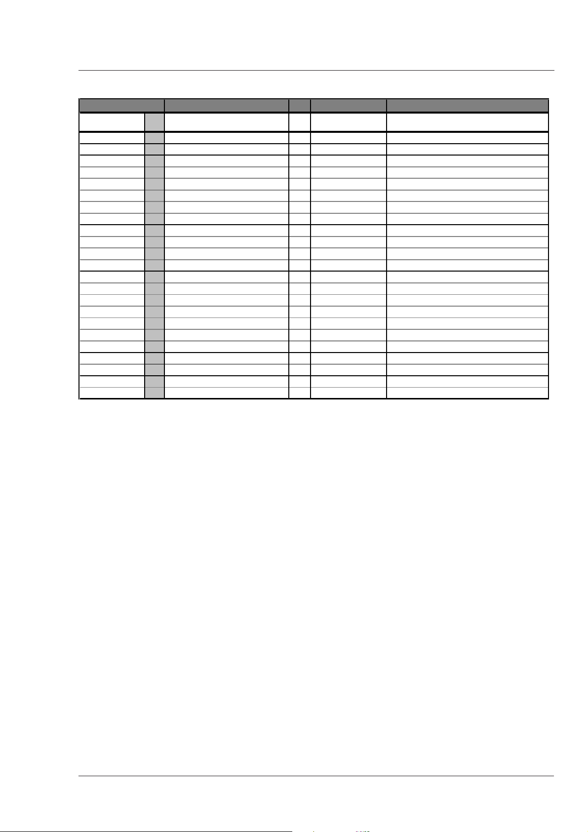
Menu UL
Install
User Lev 0-1 0,1,2,3,4 4 Max user level User level select
Cam Nr 2 1-15 0 Camera number indication
Timing 2 >>
Timing 2 CPU,On CPU
Subc Crs 2 0,90,180,270 0 Timing On Subcarrier timing coarse
Subc Fine 2 00-99 50 Timing On Subcarrier timing fine
H-Phase 2 00-99 50 Timing On Horizontal phase
Notch 2 On,Off Off Colour bar Off Notch switch
Vf 0-1 >>
Txt Mode 0-1 On,Tim Tim Menu display mode
Txt Time 0-1 00-99 10
Dual PIP 0-1 On,Off Off Support for 2 PIPs in VF
Gain
Gain 2 function identification text
-= 2 -6,-3 -3 Gain value for - indication
02
+= 2 3,6,9,12,15,18,21,24,27 6 <++ Gain value for + indication
++= 2 6,9,12,15,18,21,24,27,30 12 >+ Gain value for ++ indication
Combine
Diskrec
Lighting
Advanced 2 Opt,Goo,Fai,Poo,Ext Opt MKII See Section 3 "Artificial light conditions"
Basic 2 On, Off Off No MKII Basic artificial lighting accomodation
Available Choices Def Available if ... Explanation
0-1 >>
VF-Disp is Tim
2>>
2 On,Off On Interpolation Mode
2 EVS, STD STD MKII Set diskrecorder to EVS or Standard
2 >> Artificial lighting accomodation settings
Menu display time in 0.1 sec
Appendix Operator's Manual LDK 23HS mkII - HS Camera System A-7
Page 68

Menu UL Available Choices Def Available if ... Explanation
Files
Filenr 2 1-4,Std,Ins Scene file number select
Recall 2 Ok,Nok,Exe Scene file recall switch
Store 2 Ok,Nok,Exe Scene file store switch
2>>
Menu UL Available Choices Def Available if ... Explanation
Diagn
Software 2 >>
Camera 2 >> Shows 12NC and status software
Battery 2 >>
Memory 2 Ok,Nok,Low Shows status of memory battery
Power 2 Ok,Nok,Low Shows status of power battery
Comm 2 >>
CPU 2 Yes,No,Illegal Shows connectivity to CPU
OCP 2 Yes,No Shows connectivity to OCP
MCP 2 Yes,No Shows connectivity to MCP
Boards1 2 >>
Video1 2 >> Shows 12NC, status, serialnumber and
Video 2 2 >> production date of specific module
SyncShad 2 >>
Data Cam 2 >>
Vid Misc 2 >>
Boards 2 2 >>
VideoMux 2 >> Shows 12NC, status, serialnumber and
AudioTxR 2 >> production date of specific module
Audio Lf 2 >>
Pulse Pat 2 >>
ShutFilt 2 >>
CntlUnit 2 >>
Boards 3 2 >>
BckPanel 2 >> Shows 12NC, status, serialnumber and
DC Conv 2 >> production date of specific module
LLA 2 >>
5" VF 2 >>
7" VF 2 >>
2>>
A-8 Operator's Manual LDK 23HS mkII - HS Camera System Appendix
Page 69

List of Menu Functions
Function Path in Menu Function Path in Menu
Aspect ratio Operate \ Sensor
Select switch Operate \ Sensor \ Asp Ratio
Source switch input Operate \ Sensor \ Asp Ratio
Audio Operate \ Audio
Audio 1 level select Operate \ Audio
Audio 2 level select Operate \ Audio
Auto lighting Operate \ Sensor \ Shutter
Auto white balance Operate \ Gain
Battery status
Memory Diagn \ Battery
Power Diagn \ Battery
Black Setup \ Black
Auto level Setup \ Black
Blue level Setup \ Black
Green level Setup \ Black
Red level Setup \ Black
Master Operate \ Black
Black stretch
Level Operate \ Black
Switch Operate \ Black
Boards Diagn \ Boards
Cadre Vf/Lens \ Vf Inst \ Markers
Camera number Install \ CamNr
Centre cross Vf/Lens \ Vf Inst \ Markers
Clean scan Operate \ Sensor \ Shutter
Colour bar switch Operate \ Test
Colour temperature Operate \ Gain
Communication Diagn \ Comm
Contour
Coarse/fine level Setup \ Contour \ Contour
Level Operate \ Contour
Level dependence Setup \ Contour \ Contour
Noise slice level Operate \ Contour
Soft level Operate \ Contour
Soft switch Operate \ Contour
Source Operate \ Contour
Source Setup \ Contour
Switch Operate \ Contour
Switch Setup \ Contour
Vertical level Operate \ Contour
Exposure time Operate \ Sensor \ Shutter
Filter Vf/Lens \ Lens
Flare
Switch Setup \ Flare
Level Blue Setup \ Flare
Level Green Setup \ Flare
Level Red Setup \ Flare
Focus
Indication Vf/Lens \ Lens
Indication switch Vf/Lens \ Vf Inst \ Indicat.
Gain Setup \ Gain
Blue gain Setup \ Gain
Red gain Setup \ Gain
Green gain Setup \ Gain
Switch Operate \ Gain
Values Install \ Gain
Gamma
Switch Setup \ Gamma
Blue level Setup \ Gamma
Master level Setup \ Gamma
Red level Setup \ Gamma
H-phase Install \ Timing
Intercom
Cam headph. eng Setup \ Intercom
Cam headph. prod Setup \ Intercom
Cam headph. prog Setup \ Intercom
Cam mic Setup \ Intercom
Sidetone Setup \ Intercom
Tracker mic Setup \ Intercom
Interpolation mode Install \ Combine
Iris
Auto Operate \ Iris
Indication switch Vf/Lens \ Vf Inst \ Indicat.
Peak/average Vf/Lens \ Iris
Set point Vf/Lens \ Iris
Knee Setup \ Knee
Limit level Setup \ Knee
Point Blue Setup \ Knee
Point Master Setup \ Knee
Point Red Setup \ Knee
Slope Blue Setup \ Knee
Slope Master Setup \ Knee
Slope Red Setup \ Knee
Switch Operate \ Knee
Lens
Filter Vf/Lens \ Lens
Focus indication Vf/Lens \ Lens
Heater Vf/Lens \ Lens
Manufacturer id Vf/Lens \ Lens
Range extender ind. Vf/Lens \ Lens
Remote indication Vf/Lens \ Lens
Zoom indication Vf/Lens \ Lens
Matrix switch Operate \ Matrix
Menu display
Mode Install \ Vf
Time Install \ Vf
Notch filter switch Install \ Timing
Appendix Operator's Manual LDK 23HS mkII - HS Camera System A-9
Page 70

Function Path in Menu
PIP
Border Vf/Lens \ Vf Inst \ PIP
Dual PIP switch Install \ Vf
Location Vf/Lens \ Vf Inst \ PIP
Reverse mode Vf/Lens \ Vf Inst \ PIP
Size Vf/Lens \ Vf Inst \ PIP
Switch Vf/Lens \ Vf Inst \ PIP
Range extender Vf/Lens \ Lens
Safe area Vf/Lens \ Vf Inst \ Markers
Sawtooth switch Operate \ Test
Sidetone Setup \ Intercom
Scene file
Number select Files
Recall switch Files
Store switch Files
Shading
Blue Setup \ Shading
Green Setup \ Shading
Red Setup \ Shading
White Setup \ Shading
Software camera Diagn \ Software
Subcarrier timing
Coarse Install \ Timing
Fine Install \ Timing
User level Install \ User Lev
Viewfinder
Contour level Vf/Lens \ Vf Inst
Contour select Vf/Lens \ Vf Inst
External select Vf/Lens \ Vf Inst
Monitor select Vf/Lens \ Vf Inst
White level marker Vf/Lens \ Vf Inst \ Markers
Zebra contrast Vf/Lens \ Vf Inst
Zebra level Vf/Lens \ Vf Inst
Zebra switch Vf/Lens \ Vf Inst
White balance Operate \ Gain
White limiter
Switch Setup \ Wh.Limit
Master level Setup \ Wh.Limit
White shading Setup \ Shading
Zebra Vf/Lens \ Vf Inst
Zoom
Indication Vf/Lens \ Lens
Indication switch Vf/Lens \ Vf Inst \ Indicat.
A-10 Operator's Manual LDK 23HS mkII - HS Camera System Appendix
 Loading...