

Page 1

Contents
1
Specifications ........................................................3
Quick guide ...........................................................4
Sockets on the rear of the unit.................................................4
Mains power and speaker sockets 30LB020S4.................... 4
Connecting to the mains power supply.................................. 4
Front of TV................................................................................. 4
Switching on the unit ................................................................ 5
Selecting TV mode on the remote control............................. 5
Switching the TV on and to standby mode ...........................5
Selecting channels......................................................................5
Selecting inputs .......................................................................... 5
Television reception via the antenna cable............................5
Television reception via Scart socket
(e.g. SAT or cable receiver)...................................................... 5
Preparations..........................................................6
Setting up, care and maintenance....................................6
Place of installation.................................................................... 6
Cleaning.......................................................................................6
Instructions for waste disposal ................................................ 6
Maintenance................................................................................ 7
Scope of delivery................................................................7
Setting up and installing the 30LB020S4......................7
Fitting the base ........................................................................... 7
Fixing and connecting the speakers........................................7
Connections...........................................................8
Connections.........................................................................8
Connection elements on the set............................................... 8
Connection elements on the rear of the unit..........................8
Antenna / cable connection...................................................... 9
Connecting the headphones..................................................... 9
Connecting external auxiliary equipment.............................. 9
Mains connection.......................................................................9
Operation.............................................................10
Controls .............................................................................10
Front of TV...............................................................................10
Remote control.........................................................................10
Inserting the batteries ..............................................................10
Using the remote control for other equipments ..........11
Initial startup procedure..................................................13
Menu navigation ..............................................................12
Operation...........................................................................13
Switching on/off ......................................................................13
Channel selection..................................................................... 13
Sleep mode................................................................................13
Setting channels ....................................................................... 13
Unit configuration....................................................................13
Storing channels automatically..............................................14
Direct channel input / fine tuning..........................................14
Allocating and deleting channels ..........................................15
Picture and sound ....................................................................15
Adjusting the picture settings ................................................ 15
Adjusting tone settings............................................................ 16
Channel-specific settings........................................................16
The Panorama Sound decoder...............................................17
The Dolby Virtual Surround Sound Decoder..................... 17
Decoder mode selection .........................................................17
Normal television sound.........................................................17
Dolby Virtual Surround Sound and Panorama................... 18
Special functions..............................................................19
Fade-in display window .........................................................19
The function buttons ..............................................................19
Timer..........................................................................................19
Childproof lock........................................................................ 20
PIC (Picture in computer)
......................................................
20
Resetting to delivery status.....................................................21
PC mode............................................................................21
Selecting inputs........................................................................ 21
Setting the language and adjusting screen settings............ 21
Teletext ..............................................................................22
Teletext signals.........................................................................22
Selecting teletext ...................................................................... 22
Page memory facility.............................................................. 22
Favourite pages........................................................................ 22
TOP / FLOF teletext................................................................ 23
Multiple pages..........................................................................23
Other teletext functions...........................................................24
Auxiliary equipment...........................................25
Auxiliary equipment........................................................25
Connecting auxiliary equipment...........................................25
Connecting to external AV sources.......................................25
Selecting sockets......................................................................26
Additional devices with switching voltage ......................... 27
Copy function / recording via Scart sockets ....................... 27
Assigning the Scart sockets ................................................... 27
Index.....................................................................28
En
Page 2
Overview
2
En
Page 3
Specifications
3
Specifications
Model *
15LB020S4
20LB020S4
23LB020S4
30LB020S4
General:
Display
TFT LCD
Picture format
4:3
16:9
Screen diagonal
(38 cm)
(51 cm)
(58 cm)
(75 cm)
Picture resolution
1024 x 768 (XGA)
640 x 480 (VGA)
1280 x 768 (WXGA)
1280 x 768 (WXGA)
Pixel pitch (mm)
0.300 x 0.300
0.6375 x 0.6375
0.1305 x 0.3915
0.5025 x 0.1675
Brightness
400 cd/m2
450 cd/m2
450 cd/m2
450 cd/m2
Contrast ratio
350:1
400:1
400:1
350:1
Channel memory
99 + 2
99 + 2
99 + 3
99 + 3
Tuner **
PAL-SECAM B/G,D/K,I,L/L`, NTSC playback 3.58 MHz, 4.53 MHz
Tuning
Automatic transmitter memory
Audio
A2/NICAM stereo
Dolby Virtual
Surround Sound
4
Teletext memory
100 pages,
TOP/FLOF text
500 pages,
TOP/FLOF text
Removable
loudspeakers
No
4
Removable base
4
Microsoft Windows
compatible
4
MAC OS
compatible
4
Sockets:
Headphones
4
Antenna (75 Ohm)
4
Scart sockets
2
3
DVI In
4
PC In (15-pin D-Sub)
4
Speaker Out
No
4
DC In
4
No
Power supply
External power pack
12 V DC
External power pack
24 V DC
Integral
power pack
* The TV type is clearly visible on the type plate
located on the rear of the unit, e.g.:
Type:
15LB020S4
Note:
Statistically speaking, every display or flat screen has a
certain number of faulty pixels.
From a production viewpoint, this is unavoidable.
No manufacturer can guarantee 100% faultless screens,
even with the strictest quality controls.
** The TV standard is clearly visible on the type plate located on
the rear of the unit:
Type: …/P
PAL B/G
NTSC playback
3.58 MHz
4.43 MHz
Type: ... / ..
NICAM B/G, I, L
SECAM B/G, D/K, L, L’
NICAM B/G, I, L
NTSC playback
3.58 MHz
4.43 MHz
En
Page 4
Quick guide
4
En
Quick guide
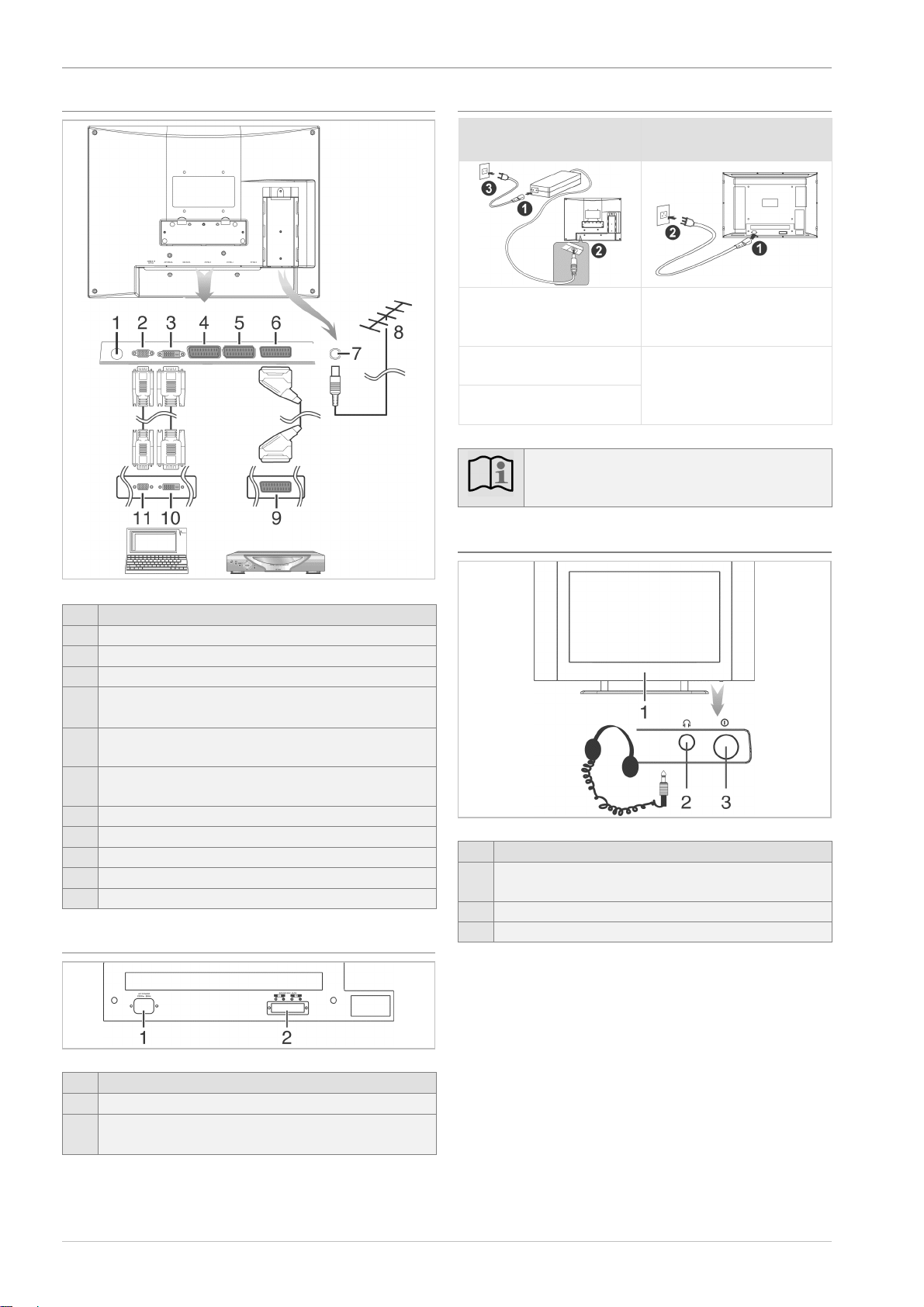
Sockets on the rear of the unit
Item
Designation
1
Socket for power pack (not with 30LB020S4)
2
VGA input socket
3
DVI input socket
4
Scart 3 socket (only 23LB020S4 and 30LB020S4)
Input only
5
Scart 2 socket
Input only
6
Scart 1 socket
Input and output
7
Socket for antenna cable (75 ohm)
8
Domestic antenna or cable system
9
Scart output socket e.g. for a SAT receiver
10
DVI output socket e.g. for a PC, DVD player
11
VGA output socket e.g. for a PC
Mains power and speaker sockets 30LB020S4
Item
Designation
1
Mains connection socket
2
Speaker socket
(left +, left -, right -, right +)
Connecting to the mains power supply
15LB020S4, 20LB020S4,
23LB020S4
30LB020S4
1. Plug the mains cable into
the power pack
1. Plug the mains cable into
the mains socket on the
TV
2. Plug the cable on the
power pack into the TV
3. Plug the mains cable into
the socket
2. Plug the mains cable into
the socket
Note:
Always use power packs that are supplied by the manu-
facturer to avoid invalidating the warranty.
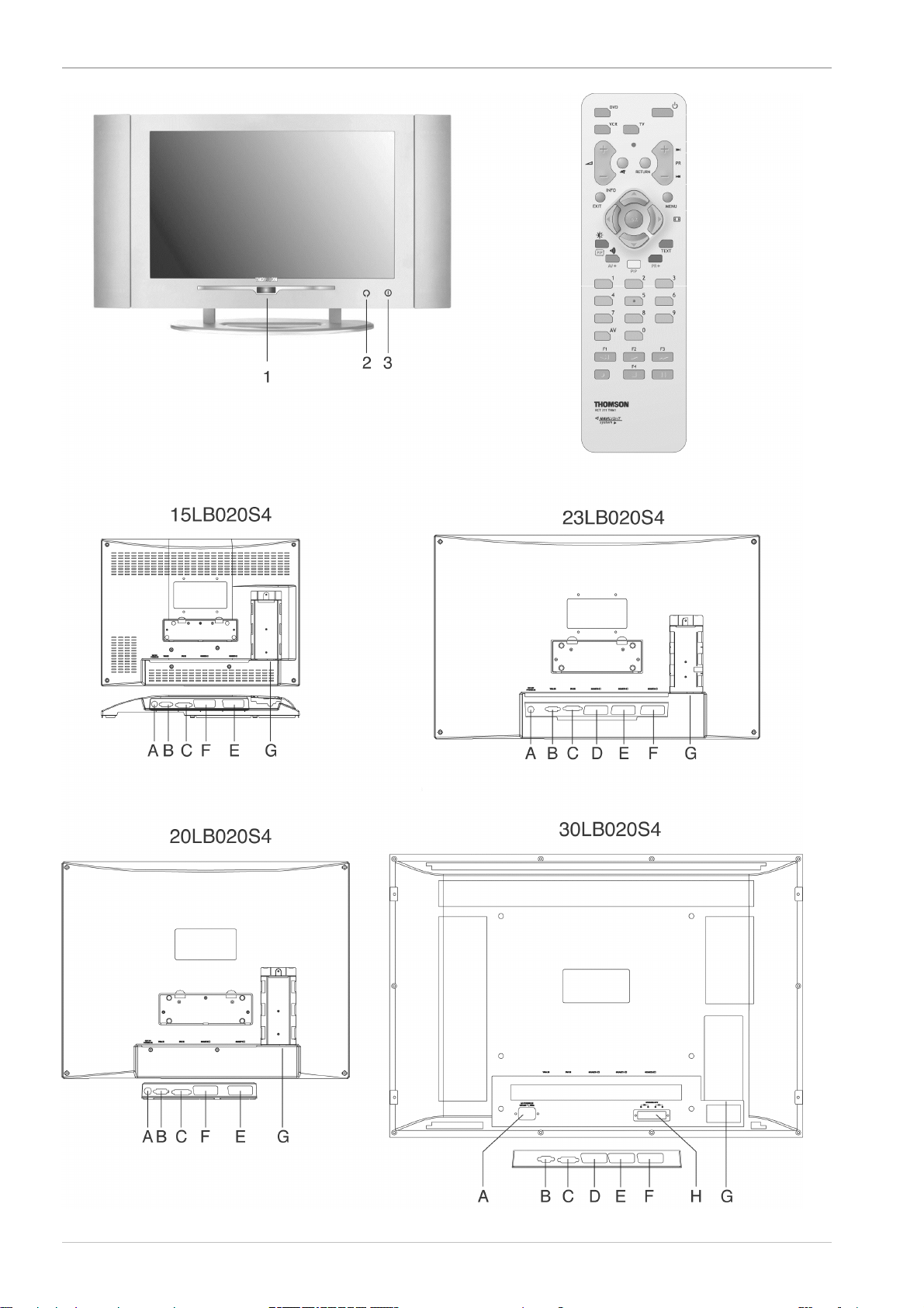
Front of TV
Item
Designation
1
Remote control receiver and
standby indicator
2
Headphone socket (3.5 mm jack)
3
Power switch
Page 5
Quick guide
5
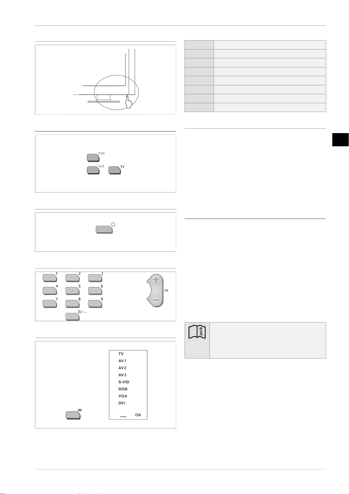
Switching on the unit
Selecting TV mode on the remote control
Switching the TV on and to standby mode
Selecting channels
Selecting inputs
1. Select the input using arrow buttons Ÿ / ⁄.
2. Press the OK button 24 to store the setting.
TV
Antenna (75 Ohm)
AV 1
Signal input and output
AV 2
Signal input
AV 3
Signal input (only 23LB020S4 and 30LB020S4)
S-VHS
S-VHS input (via Scart 2)
RGB
Signal with maximum picture quality (via Scart 1)
VGA
VGA input
DVI
DVI input
Television reception via the antenna cable
1. Connect domestic antenna or cable system
(see no. 7 Sockets on the rear of the unit page 4).
2. Connect TV set to the power supply
(see Connecting to the mains power supply page 4).
3. Select TV input (see Selecting sockets page 26).
4. Start automatic search
(see Initial startup procedure page 13).
5. Select channels: use the arrow buttons Ÿ / ⁄ or numerical
buttons 28 (see Channel selection page 13).
Television reception via Scart socket (e.g. SAT or cable
receiver)
1. Connect SAT receiver (see no. 4, 5 or 6 Sockets on the rear of
the unit page 4).
2. Connect TV set to the power supply
(see Connecting to the mains power supply page 4).
3. Select Scart input (AV 1, AV 2 or AV 3, see Selecting sockets
page 26).
Usually the Scart input is assigned to the first TV channel position and adjusted via the arrow buttons Ÿ / ⁄.
4. Set up and switch on SAT receiver (see SAT receiver instruction manual).
5. Select channels:
Do not use PR + / - buttons or numerical buttons, instead use
the SAT receiver (see SAT receiver instruction manual).
Note:
If the television reception is input via a SAT receiver
and the channel position in the TV changes, the correct
Scart input must be assigned to the new channel position (see Point 3).
En
Page 6
Preparations
6
En
Preparations
Setting up, care and maintenance
Place of installation
Caution!
Protect the television against humidity and rain. The TV
set should not be operated in rooms with high moisture
levels. Do not place receptacles containing water on the
TV, e.g. vases, flower pots. The combination of electrical current and water can cause fatal electric shocks.
Make sure that no objects can fall through the ventilation slits into the interior of the television as they may
touch live parts.
Should any liquids or foreign objects fall into the interior of the television, disconnect the television from the
power supply immediately. Have the television checked
by a specialist before using it again.
Note:
If the television is moved from a cold to a warm place,
condensation may develop inside the television. Leave
the television switched off for a few hours.
Moisture in rooms where the set is installed should not
exceed 85% humidity.
Caution!
Make sure that the unit (most importantly the screen)
does not come into contact with hard objects, especially
during transportation!
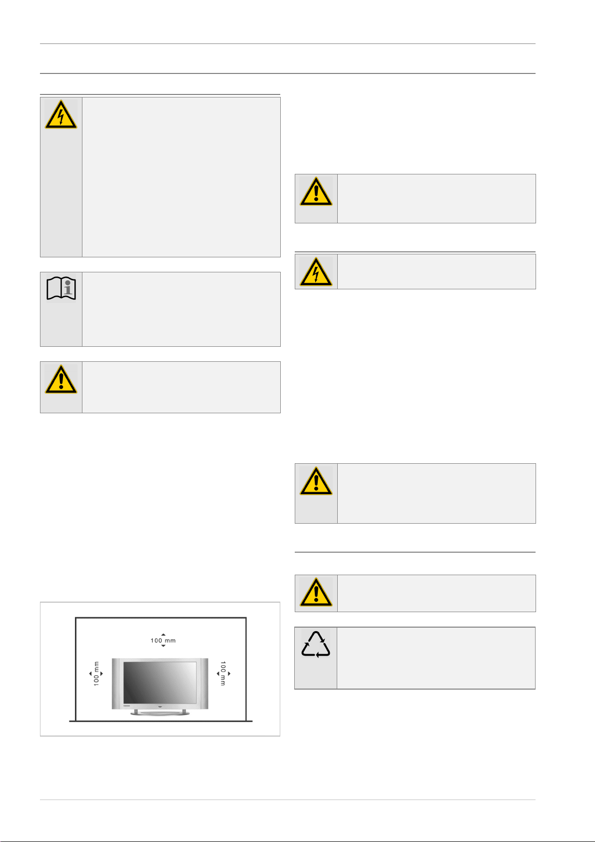
The place of installation should provide a stable, horizontal, vibration-free surface to ensure that the television stands safely and is not
exposed to any vibrations. Vibrations could damage the sensitive
electronics.
Any warmth generated when the television is operated must be allowed to escape freely. The ventilation slits on the reverse side must
always be kept free. Do not cover the ventilation openings with
curtains, cloths or newspapers.
Avoid direct thermal effects from radiators or sunlight. If in doubt,
consult a specialist dealer. Heat build-up may cause electronic components to fail!
The maximum ambient temperature should not exceed 350 celsius.
Position the TV in such a way that bright light or sunshine cannot
fall onto the screen. Light sources of this kind will reflect off the
screen and interfere with the brilliance of the picture.
Do not install the television set near equipment generating strong
magnetic fields (e.g. motors, loudspeakers, transformers, etc.) as
these may cause colour changes on the screen.
Caution!
Viewers should maintain a distance of 2-3 metres (4
times the diagonal of the image) from the screen to
protect their eyes while watching television.
Cleaning
Caution!
Disconnect the mains plug before cleaning.
• Do not expose the surface of the screen to temperatures above
+ 80 °C and below – 40 °C!
Protect the television against extreme humidity.
• Do not write on the surface of the screen with a biro or felt-tip
pen!
• Only use a cotton cloth to clean the screen.
• If necessary, use a cotton cloth and small quantities of diluted,
non-alkaline soapy solution that is water-based or alcohol-based.
• Do not use any of the following substances:
Salt water, insecticide, chlorine or acidic solvents (ammonium chloride), scouring powder.
• Gently clean the surface with the cotton cloth until it is dry.
Caution!
Never
• wipe the screen using window cleaner
• treat with foam products
• clean by polishing or scouring.
Instructions for waste disposal
Packaging and packaging aids can and always should be recycled.
Caution!
Packaging materials, such as e.g. foil bags, must be kept
away from children (Danger of suffocation!).
Note:
Before disposing of the unit, please remove any batteries! The unit and batteries can be handed in at a collection point for hazardous waste or at your local recycling
centre, for example. Please consult your local authority!
Page 7
Preparations
7
Maintenance
Electronic components are subject to a natural ageing
process. In the event of malfunctions, please consult a specialist
dealer. Only use the original packaging for transporting the unit.
Caution!
The unit is operated at dangerous voltages. The unit
may only be opened by an authorised specialist. All
maintenance and servicing work must be carried out by
an authorised company. Repairs that are carried out incorrectly could result in fatal injuries to the user.
Unauthorised tampering with the inside of the TV invalidates the
warranty.
Note:
To make it easier to identify your television when
handed over to customer services, state the identification number printed on the type plate on the rear of the
unit.
The manufacturer shall not warrant for any damage caused by improper maintenance and repair work by third parties.
Caution, risk of burning-in!
Reproducing a still image for longer periods has a
negative effect on the picture quality. Burn-in images
and permanent effects on the screen can be avoided by
implementing a series of basic precautionary measures.
Observing the following recommendations will ensure
that the television delivers satisfactory results in the long
term:
Avoid frequent playback of the same image and moving images with static areas (e.g. fixed fade-ins in the
image or video games with areas that do not move).
Do not view the same teletext page for long periods.
Avoid playing back on-screen fade-ins from a decoder,
DVD player, video recorder or other equipment for
long periods.
When you use the freeze-frame function on a television,
video recorder, DVD player or other equipment, do not
leave the picture on freeze-frame or pause for long periods.
Pictures with extremely light and extremely dark areas
beside one another should not be played back for long
periods.
After use, always switch the display back to standby
mode!
Scope of delivery
• 1 x LCD TV
• 1 x power pack (not with 30LB020S4)
• 1 x mains cable
• 1 x base (with LCD TV 30LB020S4, not preassembled)
• 1 x remote control
• 2 x batteries AAA 1.5 volt for remote control
• 1 x antenna cable
• 2 x speakers (only 30LB020S4)
• 2 x speaker cable (only 30LB020S4)
• 1 x instruction manual
Setting up and installing the 30LB020S4
To set up the 30LB020S4 LCD TV, please proceed as follows:
Fitting the base
• Fit the base to the rear of the unit using the screws (x 4) sup-
plied.
• Check that the screws are seated correctly.
Fixing and connecting the speakers
Note:
Only the speakers supplied should be connected to the
television.
• Fix the speakers supplied to the housing using the screws pro-
vided (2 for each speaker). Or position them in the desired location around the television.
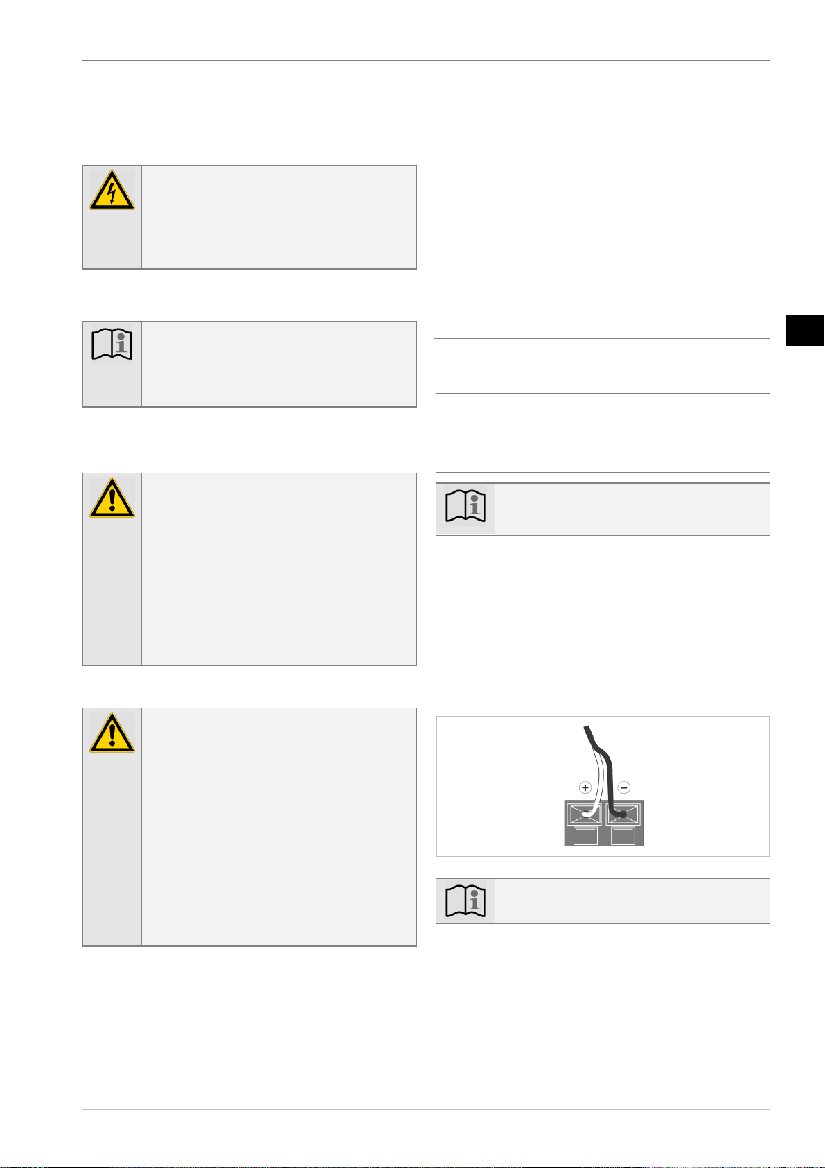
• Connect the speakers to the terminal connectors on the rear of
the unit. Press down the terminal levers to plug in the speaker
cables. Use the speaker cables supplied and make sure that
they are connected correctly (left +, left -, right +, right -). The
black wire in the speaker cable must be secured to the black
(–) terminal on the television. The second wire must be connected in the same way.
Note:
Only plug in the stripped end of the speaker cable!
En
Page 8

Connections
8
En
Connections
Connections
See Overview on page 3.
Connection elements on the set
Item
Designation
2
Headphone socket for connecting headphones with a 3.5 mm
jack
Connection elements on the rear of the unit
15LB020S4
Item
Designation
A
DC IN: Connecting the external power pack (12 V DC)
to the power supply
B
VGA IN: Connecting a PC via a VGA cable
C
DVI IN: Connecting a PC or similar via a DVI cable
E
Scart 1: Scart socket (EURO-AV) for RGB input and AV
signal input / output (picture and sound)
F
Scart 2: Scart socket (EURO-AV) for
AV signal input (picture and sound) and S-VHS input
G
ANTENNA 75 W:
Connection for 75-ohm antenna/cable system
20LB020S4
Item
Designation
A
DC IN: Connecting the external power pack (12 V DC)
to the power supply
B
VGA IN: Connecting a PC via a VGA cable
C
DVI IN: Connecting a PC or similar via a DVI cable
E
Scart 1: Scart socket (EURO-AV) for RGB input and AV
signal input / output (picture and sound)
F
Scart 2: Scart socket (EURO-AV) for
AV signal input (picture and sound) and S-VHS input
G
ANTENNA 75 W:
Connection for 75-ohm antenna/cable system
23LB020S4
Item
Designation
A
DC IN: Connecting the external power pack (24 V DC)
to the power supply
B
VGA IN: Connecting a PC or similar via a VGA cable
C
DVI IN: Connecting a PC or similar via a DVI cable
D
Scart 3: Scart socket (EURO-AV) for AV signal input (pic-
ture and sound)
E
Scart 1: Scart socket (EURO-AV) for RGB input and AV
signal input / output (picture and sound)
F
Scart 2: Scart socket (EURO-AV) for AV signal input (pic-
ture and sound) and S-VHS input
G
ANTENNA 75 W:
Connection for 75-ohm antenna/cable system
30LB020S4
Item
Designation
A
AC IN: Connecting the integral power pack to the power
supply via the mains cable
B
VGA IN: Connecting a PC via a VGA cable
C
DVI IN: Connecting a PC or similar via a DVI cable
D
Scart 3: Scart socket (EURO-AV) for AV signal input (pic-
ture and sound)
E
Scart 1: Scart socket (EURO-AV) for RGB input and AV
signal input / output (picture and sound)
F
Scart 2: Scart socket (EURO-AV) for AV signal input (pic-
ture and sound) and S-VHS input
G
ANTENNA 75 W:
Connection for 75-ohm antenna/cable system
H
SPEAKER OUT: Terminal connectors for external speakers
Page 9
Connections
9
Antenna / cable connection
Your unit is supplied with a high-grade antenna cable with high
shielding degree.
To connect the domestic antenna or cable system, plug this cable
into the socket for the external antenna and the output socket on the
television. Avoid cable looping near the TV set for optimum reception.
If a video recorder or satellite receiver is to be connected up, please
refer to Auxiliary equipment on page 25.
Connecting the headphones
Connection socket 2 is supplied for all normal headphones sold with
a 3.5 mm jack. For other jacks, use adapters available from specialised stores.
Note:
Integral speakers are switched off when headphones are
used.
Caution!
Excessively high volumes can damage your hearing,
especially when wearing headphones.
Connecting external auxiliary equipment
Scart sockets D, E and F on the back of the unit offer extensive connection options. To connect external equipment, see
page 25.
Note:
The menu and teletext displays are not available from
the Scart sockets as an output signal and cannot be
picked up as a result.
Mains connection
Caution!
The unit should only be connected to the mains supply
once all other connections have been made. When disconnecting the mains cable from the socket, pull on the
mains plug and not on the cable.
Caution!
The LCD TV 30LB020S4 should only be connected to
a power supply voltage of 230 V / 50 Hz with a protective earth conductor.
15LB020S4, 20LB020S4,
23LB020S4
30LB020S4
1. Connect mains cable to
power pack
1. Plug the mains cable into
the mains socket on the
TV
2. Plug the cable on the
power pack into the TV
3. Plug the mains cable into
the socket
2. Plug the mains cable into
the socket
Caution!
If the mains plug on the TV power cable is faulty or if
the unit shows other signs of damage, it should not be
used.
Remove the mains cable from the socket by pulling out
at the plug – do not pull on the cable.
Note:
Always use power packs that are supplied by the manu-
facturer to avoid invalidating the warranty.
Caution!
Use an appropriate power supply and avoid using multiple socket outlets!
To avoid damage caused by thunderstorms, pull out the
mains and antenna sockets during the storm.
Do not touch power supply plugs with wet hands - risk
of electric shocks!
En
Page 10

Operation
10
En
Operation
Controls
Front of TV
Item
Designation
1
Remote control receiver and standby indicator
2
Headphones socket
3
Power switch
Remote control
If the equipment is operated with the remote control, observe the
following:
The supplied remote control can control up to five different devices:
TV, VCR, DVD. To operate the device, press the TV button:
- Point the remote control (transmitter) at remote control receiver 1
on the unit.
- An optical connection must be established between the transmitter
and the receiver.
- If the range of the remote control decreases, replace the batteries.
Item
Designation
Switches off the TV temporarily (ready for operation);
the red standby indicator 1 lights up. Press the button
again to switch the TV back on.
PR+/-!
Switching through each individual channel position.
RETURN
No function
MENU
Displays the menus
Ÿ / ⁄
To select menu options.
ÿ
To select the picture format in TV mode.
Purple key
For changing to teletext mode.
Blue key
To scroll TV channels in the PIP picture.
0
9
Number buttons for
- selecting channel position
- entering values in the menus.
F1-F2
F3-F4
Can be set for various functions.
Yellow key
To display / increase / erase PIP picture.
Green key
- Opening the Sound menu.
- Scrolling forwards page by page in teletext mode.
- To scroll AV programmes in the PIP picture.
Red key
- Opening the Picture menu.
- Scrolling back page by page in teletext mode.
- To change PIP position.
Item
Designation
! / ÿ
To set functions, change values, enable and disable functions.
OK
Memory / confirm button
EXIT
To quit
- the menus.
- Teletext.
INFO
Status information on the current channel.
Volume setting.
For switching off the sound. Pressing the button again
switches the sound back on.
TV
To access TV mode.
VCR
To access VCR mode.
DVD
To access DVD mode.
Inserting the batteries
The batteries should be removed if the remote control is not used for
long periods. Otherwise, the batteries may leak and damage the remote control.
Caution!
The batteries for the remote control should be kept out
of the reach of children. Swallowing batteries can seriously damage your health.
Standard batteries must not be recharged, heated or exposed to naked flames (risk of explosion).
Make your own contribution to protecting the environment!
Note:
Flat batteries and storage batteries should not be disposed of together with standard household
waste. They can be deposited at the collection point for
used batteries and hazardous waste.
Please consult your local authority!
It may also be possible to return discharged
batteries to a specialist dealer or retailer.
Page 11

Operation
11
Fr
Using the remote control for other equipments
The remote control supplied with your set can be used for
other equipment, such as video recorders or DVD players.
This page provides information concerning the remote
control’s use with these types of equipment.
VCR
DVD
VCR
Press the VCR
button
On/Standby
DVD
Press the DVD
button
On/Standby
MENU
OK
To display the main
menu
Vertical scrolling in
menus
Horizontal scrolling
in menus
To confirm an action
To display the main
menu
Vertical scrolling in
menus
Horizontal scrolling
in menus
To confirm an action
EXIT
0-9
PR+/PR-
AV
REV
PLAY
FWD
STOP
PAUSE
REC
To close a menu
To directly access
channels or enter
numeric values
To change channels
To select AV input
Rewind
Play
Fast forward
Stop
Pause picture
Record
To close a menu
To enter numeric
values or select
options in menus
Rewind
Play
Fast forward
Stop
Pause picture
Programming the remote control
Automatic code search
This method can be used to automatically find the most
appropriate code for your appliance.
1. Switch on the appliance you wish to use the remote
control with.
2. Press the relevant button for this appliance on the remote
control, and while holding this button down, press the
standby button until the remote control light comes on.
Release the two buttons.
3. Point the remote control at the appliance and press
PLAY. Wait until the light stops flashing. If the appliance
has not gone into standby mode after five seconds, press the
PLAY button again to continue the search for the next set of
codes.Repeat this operation until the appliance goes into
standby mode. There are 20 sets of codes.
4. When the appliance goes into standby mode, press the
standby button on the right side to switch it on again.
Then press the REV button to put it back in standby mode,
and if necessary, keep pressing until the appliance goes into
standby.
5. Press the STOP button and hold it down until the remote
control light goes off.
Note: you can cancel the programming operation at any
time by pressing the EXIT button.
Manual programming
This method involves carrying out a manual search for the
codes to be used for controlling your other appliances.
1. Switch on the appliance you wish to use the remote
control with.
2. Press the relevant button for this appliance on the remote
control, and while holding this button down, enter one of
the codes relevant to your make of appliance (there is a list
of codes at the end of this manual). If the remote control
light flashes you have entered the wrong code or it is not
possible to program the remote control.
3. Point the remote control at the appliance and press the
relevant button (VCR or DVD). Press the standby button.
If the appliance does not go into standby mode, try another
code.
Depending on the year of manufacture and the type of
appliance, some functions may not be available.
Certain codes may cover more functions than others. Test
the functions you can control and, if appropriate, try other
codes.
Note here the code(s) which work best.
When you change the remote control’s batteries,
remember to reprogram it.
En
Page 12

Operation
12
Initial startup procedure
When setting up for the first time, proceed as follows:
1. Switch the unit on at the power switch (3). Then press the
button on the remote control. The standby indicator (1)
goes out. The following Installation Menu appears on the
screen the first time the unit is switched on, or before the
first channel is stored:
Note:
Every time the TV is switched on, a starting sequence
appears on the screen displayed as a white stripe.
Note:
If for some reason the set has already been switched on,
the installation menu no longer appears automatically. If
this is the case, to save the station, see page 14.
2. Select the required line by pressing the arrow buttons
Ÿ / ⁄ and change the relevant setting by pressing the ar-
row buttons ! / ÿ.
3. Use arrow buttons Ÿ / ⁄ to move the green marker back
to the Search line.
Note:
Before the search is started, the country abbreviation
should be entered in the
Country
line and the
menu language in the
language
line.
The
Standard
line should be set to the country-
specific TV standard ("UK" for UK).
4. Automatic channel search begins when you press the righthand arrow button ÿ. All detected stations are automati-
cally assigned to the channel positions and stored in ascending order.
5. Press OK button to save; the display
Save : OK
appears
in red briefly.
6. Press the EXIT button to quit the menu.
Note:
Screen settings such as e.g. brightness and contrast were
preset by the manufacturer to provide optimised performance. You can change these settings in the Picture
menu (see page 15).
Menu navigation
For ease of operation, all operating procedures are represented on
the screen in MENU form.
Item
Meaning
1
Main menu
2
Submenu
3
Status bar
It is possible to select the language in which the menu is to be
displayed. Please read the Unit configuration section on page 13
for information on changing the menu navigation language.
1. The Main menu appears on the left-hand side of the screen
when you press MENU button. The selected submenu ap-
pears to the right next to the Main menu.
2. Use arrow buttons Ÿ / ⁄ to select the individual menu
items.
Menu item
see page
Picture
15
Sound-1
16
Install.
13
SOUND-2
17
Pr. set
16
Pref.
13
Timer
19
Lock $
20
Reset
21
3. Press ÿ to advance to the selected submenu (Main menu
item is highlighted blue).
4. To return to the Main menu from the various submenus,
select
< Return
using the arrow keys Ÿ / ⁄.
5. Press the arrow key ! to access the Main menu (Main
menu item is highlighted green).
6. Press OK button to save;
Save : OK
appears in red
briefly.
7. Press the EXIT button to exit the menu.
Note:
The menus disappear automatically after approx.
12 seconds providing no buttons are pressed on the remote control.
Page 13

Operation
13
En
Operation
Switching on/off
Actuate power switch (3) to activate standby mode. The standby
indicator lights up (1) red. To switch on the device, press the
button on the remote control. The standby indicator 1 goes out.
Press the button on the remote control to turn the active unit to
standby mode. The standby indicator lights up (1) red.
Caution!
Use an appropriate power supply and avoid using multiple socket outlets!
To avoid damage caused by thunderstorms, pull out the
mains and antenna sockets during the storm.
Do not touch power supply plugs with wet hands - risk
of electric shocks!
Channel selection
• The channels are selected directly by pressing the numeric
keys (0-9). To select channels with two-digit numbers,
press the corresponding numeric keys (0-9) in direct suc-
cession.
• Pressing arrow buttons Ÿ / ⁄ selects the channels one by
one.
• The channels can also be selected in the channel list. Press
the MENU button twice, the channel list appears on the
screen.
A channel can be selected by pressing arrow buttons!
Ÿ / ⁄.
To confirm the channel selected, press OK button.
Sleep mode
If Program is no longer received on a certain channel, e.g. after
the station signs off or if there is no antenna signal, the unit automatically switches to standby mode after approx. 7 minutes.
Note:
In AV mode (operation of an external device using one
of the Scart connection sockets on the rear of the unit),
sleep mode is disabled.
Setting channels
Unit configuration
1. Open the Pref. menu: Press MENU button.
2. Select
Pref.
in the Main menu using arrow buttons Ÿ /
⁄.
3. Press the arrow key ÿ to move the green marker to the
Pref. menu.
4. Use arrow buttons Ÿ / ⁄ to select the individual menu
items.
5. Use arrow buttons ! / ÿ to modify the relevant settings or
data.
6. When channels are stored automatically, they are sorted according to the usual order they are stored in the respective
countries. Select the corresponding country in the
Coun-
try
line. Select the menu dialogue language in the
Lan-
guage
menu item.
Various functions can be assigned to buttons F1-F2-F3-F4
(see also page 19).
The number given in the
Nb of Pr.
line limits the amount of
channels when "zapping". Higher channel numbers will therefore be ignored when channels are selected one by one (zapping).
These channels can only be selected using the numeric keys
(0-9) on the remote control and in the channel list.
7. Press the OK button to store the settings.
8. Press the EXIT button to quit the menu.
En
Page 14

Operation
14
Storing channels automatically
1. Open the Install. menu: Press MENU button.
2. Select
Install.
in the Main menu using arrow buttons
Ÿ / ⁄.
3. Press arrow button ! / ÿ to move the green marker to the
Install. menu.
4. Select
Search
using arrow buttons Ÿ / ⁄.
5. Press arrow buttons ! / ÿ to start the search. All stations
received are automatically stored in the channel positions in
ascending numerical order.
6. Press EXIT button to stop the search early.
7. If the video recorder channel position is also to be programmed automatically, then connect the video recorder
correctly with the antenna (HF) and play a pre-recorded
cassette. Refer to the instruction manual for the video recorder to carry out this procedure.
8. Press OK button to save;
Save : OK
appears in red
briefly.
9. Press the EXIT button to quit the menu.
The station identification abbreviations (Name) can still be modi-
fied later.
If the picture is just black/white or there is no sound or interference is evident on some channels, the standard
Standard
and
the
Norm
be adjusted accordingly in the Install. menu.
Direct channel input / fine tuning
1. Open the Install. menu: Press MENU button.
2. Select
Install.
in the Main menu using arrow buttons
Ÿ / ⁄.
3. Press arrow button ! / ÿ to move the green marker to the
Install. menu.
4. Use arrow buttons Ÿ / ⁄ to select the individual menu
items.
5. Use arrow buttons ! / ÿ to modify the relevant settings or
data.
6. Set the channel position to where the TV station is to be
stored under
Program.me
7. Direct channel input is carried out in the
Channel
line.
8. Use the button F1 to select between S for special channels
and ... for other channels.
9. The channel number (2-digit) can be entered easily using
the numeric buttons (0-9);
10. or the channel number can be scrolled through backwards
of forwards one by one using the arrow buttons ! / ÿ;
11. For station fine-tuning, select the
Frequency
line using
the arrow keys Ÿ / ⁄.
12. You can change the settings in 50 kHz intervals up or down
by pressing arrow buttons ! / ÿ.
13. The
Standard
and
Norm
lines should be adapted to
the country-specific TV standard.
14. Any channel name (max. 8 digits) can be specified in
Name
. The channel name appears automatically for chan-
nels with VPS/PDC.
15. Use arrow buttons ! / ÿ to select the position where the
subsequent character (letter, digit, etc.) should be entered.
16. Select the desired symbol using arrow buttons Ÿ / ⁄.
17. Use arrow buttons ! / ÿ to select a new position, etc.
Page 15

Operation
15
En
18. If the full channel name is set, quit the entry field using arrow buttons ! / ÿ.
19. Select
Tuner
in the
Source
menu line for the aerial or
cable system stations using the arrow buttons ! / ÿ.
20. Press the OK button to store the settings.
21. To allocate further channels select the channel line again
and proceed in the same way.
22. Press the EXIT button to quit the menu.
Allocating and deleting channels
1. Press the MENU button twice, the Program list appears on
the screen.
2. Use arrow buttons Ÿ / ⁄ to select the channel whose po-
sition needs to be changed.
3. Select the channel using right-hand arrow button ÿ.
4. Use arrow buttons Ÿ / ⁄ to guide the bar containing the
channel name to a new position.
5. Use left-hand arrow button ! to store the new channel po-
sition in the list.
6. If a channel is in the other bar, it can be deleted by pressing
the OK button.
7. Press the EXIT button to quit the menu.
Picture and sound
Adjusting the picture settings
Depending upon the room lighting conditions, it may occasionally be necessary to adjust the brightness, contrast or other picture
settings.
1. Open the Picture menu: Press MENU button. The title
Picture
is highlighted green.
2. Press the arrow button ÿ to move the green marker to the
Picture menu.
3. Use arrow buttons Ÿ / ⁄ to select the individual menu
items.
4. Use arrow buttons ! / ÿ to modify the relevant data. To
make modification easier, only the corresponding submenu
item appears when you press arrow buttons ! / ÿ.
5. By pressing OK button, all the changes to the picture for-
mat are saved.
6. Press the EXIT button to quit the menu.
Note:
The Picture menu can also be opened by pressing
the red button. The green marker is already located
in the Picture menu here. Press OK button to save
any changes. The menu automatically disappears
approx. 5 seconds after the last input was made.
The
Brightness
and
Contrast
settings are governed by
room brightness. The
Colour
setting is based on skin tone.
The
Sharpness
setting is a matter of personal preference.
The tone can also be adjusted to suit personal preferences. Select
between "colder" (- left) and "warmer" (+ right).
Select the desired picture format in
Format
. The television
screen can be adjusted to various transmission formats. Make
sure the picture geometry is correct.
En
Page 16

Operation
16
Adjusting tone settings
1. Open the Sound menu: Press MENU button.
2. Select Sound in the Main menu using arrow buttons Ÿ /
⁄.
3. Press arrow button ÿ to move the green marker to the
Sound menu.
4. If a stereo signal is received, the option of changing between stereo and mono reception is available in the
Nor-
mal
sound menu item.
5. Use the arrow keys Ÿ / ⁄ to select the menu items
Treble, Bass
or
Balance
.
6.
Mode (Wide/Normal
) creates the effect of acoustic
base dispersion. This gives the impression that the loud
speakers have been moved further apart from each other.
7.
AVL(On/Off
): AVl (Automatic Volume Levelling) corrects the differences in volume levels between individual
television programs and advertisements. If you prefer the
fluctuations in volume to remain, for example with music
Programs, set the AVL to Off.
8. Use arrow buttons ! / ÿ to modify the relevant data.
9. Press the OK button to store the settings.
10. Press the EXIT button to quit the menu.
Note:
The Sound menu can also be opened by pressing green
button. The green marker is already in the Sound menu.
Press OK button to save any changes. The menu auto-
matically disappears approx. 5 seconds after the last input was made.
Channel-specific settings
When switching channels there are sometimes differences in
volume and contrast. The volume and the contrast can therefore
be adjusted individually for each channel position.
1. Select the Pr. set menu: Press MENU button.
2. Select Pr. set in the Main menu using arrow buttons Ÿ
/ ⁄.
3. Press arrow button ÿ to move the green marker to the Pr.
set menu.
4. Use arrow buttons Ÿ / ⁄ to select the individual menu
items.
5. Use arrow buttons ! / ÿ to modify the relevant settings or
data.
6. Select the channel position from the
Programme
line - the
relevant channel name should appear automatically. A total
of four favourite teletext pages per channel position can be
specified in the lines
TXT-page 1 – 4
by entering the
three-digit number of a teletext page. These can then be accessed directly by pressing the F1-F2-F3-F4 function
buttons (see section The function buttons ... on page 19).
7. In the
Volume
and
Contrast
lines, adjust the values
correspondingly using the arrow buttons ! / ÿ.
8. Press the OK button to store the settings.
9. Press the EXIT button to quit the menu.
Page 17

Operation
17
En
The Panorama Sound decoder
"Panorama Sound" achieves a significant improvement of the
stereophonic sound with normal playback of stereo sound (2
channels left/right).
The integrated microcomputer ensures that the sound has depth
and is three-dimensional, even without additional amplifiers and
speakers. Thus the sound becomes "3-D".
Note:
To enjoy video playback with "Panorama Sound", a
stereo video recorder is needed.
The Dolby Virtual Surround Sound Decoder
Dolby Virtual Surround Sound is a special method for recording
sound which was principally developed for cinema film. In order
to use these atmospheric sound effects at home as well, video
tapes, television broadcasts and video discs are also produced
with this technology.
The integrated Dolby Virtual Surround Sound Decoder reproduces the Dolby Stereo cinema effect on a conventional home
entertainment system. On playback of the "Dolby Pro Logic Surround Tone", Dolby Virtual Surround Sound achieves a 3-D
sound similar to that of a home theatre system.
Even without additional speakers, the corresponding modification of the sound creates an outstanding surround effect. The listener is surrounded by the sound as if in a concert hall.
When buying video tapes, video discs and CDs, look for the
Dolby logo . It indicates that all sound and image carriers have recordings in Dolby Pro Logic Surround quality.
VHS video cassettes only marked with the logo do not
contain the necessary Dolby Surround information.
Manufactured under license from Dolby Laboratories. DOLBY,
the double-D symbol and PRO LOGIC are trademarks of
Dolby Laboratories.
Note:
A stereo video recorder is required for recording and
playing back films with Dolby Virtual
Surround Sound.
Decoder mode selection
Open the Sound-2 menu: Press MENU button. Select
Sound-
2
in the Main menu using arrow buttons!Ÿ / ⁄. Use the right-
hand arrow button ÿ to move the green marker to the Sound-2
menu for the selected decoder mode.
The desired decoder mode (see diagram) can be selected by
pressing the arrow buttons ! / ÿ if the first line of the respective
Sound-2 menu is marked green.
Normal television sound
Open the Sound-2 menu: Press MENU button. Select
Sound-
2
in the Main menu using arrow buttons!Ÿ / ⁄. Use right-hand
arrow button ÿ to move the green marker to the Sound-2 menu
of the decoder mode selected.
Select
Normal
for decoder mode by pressing the relevant ar-
row buttons ! / ÿ.
The broadcast television sound remains unaltered in this decoder
mode.
Use arrow buttons Ÿ / ⁄ to select the individual menu items.
Use arrow buttons ! / ÿ to modify the relevant settings or data.
The volume of the right and left speaker can be changed under
Balance
to achieve optimised stereo playback.
Press the OK button to store the settings. Press the EXIT button
to quit the menu.
En
Page 18

Operation
18
Dolby Virtual Surround Sound and Panorama
Open the Sound-2 menu: Press info button MENU. Select
Sound-2
in the Main menu using arrow buttons!Ÿ / ⁄. Use
the right-hand arrow button ÿ to move the green marker to the
Sound-2 menu for the selected decoder mode.
Select
Dolby Virtual
for decoder mode by pressing the
relevant arrow buttons ! / ÿ.
or select the decoder mode Panorama.
Use arrow buttons Ÿ / ⁄ to select the individual menu items.
Use arrow buttons ! / ÿ to modify the relevant settings or data.
Adjust the intensity of the surround signal under
Level
.
The volume of the right and left speaker can be changed under
Balance
to achieve optimised stereo playback.
Mode
(
Wide/Normal
) creates the effect of acoustic base
dispersion. This gives the impression that the speakers have been
moved further apart.
Press the OK button to store the settings. Press the
EXIT button to quit the menu.
Note:
In order to achieve an improvement in the 3-D sound
when playing normal stereo sound, the decoder mode –
Panorama
– must be selected.
When playing back Dolby Pro Logic Surround sound,
the decoder mode –
Dolby Virtual
– produces a 3-
D sound similar to that of a home theatre system.
Volume level adjustment for Dolby Virtual Surround Sound and
Panorama:
In order to give the sound the desired 3-D characteristics, the volume of both speakers and the intensity of the surround signal
should be tuned as precisely as possible to match the position of
the listener (e.g. sofa). This is called "noise focusing".
To adjust the level, select the decoder mode
Test
.
When the arrow buttons Ÿ / ⁄ are pressed, the test signal
generator sends the noise signal (tech.: "pink noise") alternately
(for approx. 3-5 seconds per pulse) as a surround signal and to
the individual speakers.
Adjust the intensity of the surround signal under
Level
. Under
Balance
, arrow buttons ! / ÿ can be used to adjust the volume of the relevant loudspeaker. The noise signal must sound
equally loud on both channels from the listener's position.
Note:
Once saved, the basic setting only needs to be adjusted
when the position of the listener or the TV setup
changes.
Press the OK button to store the settings. Now select the desired
decoder mode.
Page 19

Operation
19
En
Special functions
Fade-in display window
The status line with channel position, channel names, sound
mode and time is displayed by pressing the INFO button.
Otherwise the display will fade out automatically after approx. 5
seconds.
The time display only functions when a transmitter offers
teletext.
The function buttons ...
Different functions can be assigned to buttons F1, F2, F3 or F4.
1. Open the Pref. menu: Press MENU button.
2. Select Pref. in the Main menu using arrow
buttons Ÿ / ⁄.
3. Press the arrow key ÿ to move the green marker to the
Pref. menu.
4. Select either F1, F2, F3 or F4using arrow buttons
Ÿ / ⁄.
5. Use arrow buttons ! / ÿ to set the desired function.
6. Press the OK button to store the settings.
7. Press the EXIT button to quit the menu.
8. In normal TV mode, pressing the corresponding keys F1,
F2, F3 or F4 activates the defined function.
List
1. The channel list appears on the screen.
2. A channel can be selected by pressing arrow buttons!
Ÿ / ⁄.
3. To confirm the channel selected, press OK button.
Format
Switching picture format (see Adjusting the picture settings15).
The first time the button is pressed, the OSD window for the current screen format appears on the screen. The picture format
changes if the button is pressed again or at any other time. The
window disappears approx. 5 seconds after the last procedural
step is carried out.
TXT-page 1-4
Direct access to favourite stored teletext pages 1-4, see
page 16.
Clock
1. The first time the button is pressed, the time is displayed.
2. The window disappears from the screen if the button is
pressed again.
Timer
1. Open the Timer menu: Press MENU button.
2. Use arrow buttons Ÿ / ⁄ to select
Timer
in the Main
menu.
3. Press arrow button ÿ to move the green marker to the
Timer menu.
4. Use arrow buttons Ÿ / ⁄ to select the individual menu
items.
5. Use arrow buttons ! / ÿ to modify the relevant settings or
data.
Setting the timer:
1. Under
Time
, enter the hours and minutes for the switch-off
time using arrow buttons ! / ÿ.
2. Activate the
Timer
by setting it to On.
3. Press the EXIT button to quit the menu. The set automati-
cally switches to standby mode after the specified time has
elapsed.
En
Page 20

Operation
20
Childproof lock
1. Open the Lock menu: Press MENU button.
2. Select
Lock
in the Main menu using arrow buttons Ÿ / ⁄.
3. Press arrow button ÿ to move the green marker to the Lock
menu.
4. Use arrow buttons Ÿ / ⁄ to select the individual menu
items.
5. Use arrow buttons ! / ÿ to modify the relevant settings or
data.
Entering or changing the security code:
1. Select
Change code
and enter a 4-digit code using numeric buttons (0-9). Enter the same number combination
for
Confirm code
.
2. Press the OK button to store the settings.
As a precaution, you should note down your selected security
code.
The safety code
0000
is preprogrammed ex works.
Activating the childproof lock:
1. First check whether
Off
appears in the
Parental
control
line in the Lock menu. Quit the menu by
pressing the EXIT button.
2. Press the MENU button three times to display the station
list for blocking individual channels for child protection.
3. To block an individual channel, select it and confirm each
selection by pressing the red button (On). The blocked
channels are indicated by the $ icon.
4. Conversely, the individual channels can be unblocked by
pressing the green button (
Off
). The $ icon disappears.
5. Quit the menu by pressing the EXIT button.
6. Then open the Childproof lock menu. Select the
Paren-
tal control
line and set it to On.
7. Press the OK button to store the setting.
8. Quit the menu by pressing the EXIT button.
The childproof lock is only active for the channels marked with a
dollar sign $.
A message requesting code input appears on the screen if the
Childproof lock menu is then selected. The Childproof lock
menu appears only after the correct Code has been input using
the numeric buttons (0-9).
Note:
The screen is blank if a blocked channel position is selected. The
Programme under Parental
control
window appears.
The security code only has to be entered once. It can,
however, be modified at any time when the childproof
lock is not activated.
If the childproof lock is activated, access to the Install.
menu, the Pr. set menu, the Pref. menu and the Reset
menu is blocked.
The Scart sockets on the rear of the unit are also blocked
if the childproof lock is activated.
If you forgot the security code, please consult the technical customer services department or ask your dealer.
PIC (Picture in computer)
While viewing a PC picture, you can insert a video
picture.
The inserted picture can be from the antenna or from a
Scart socket.
- Press yellow key on the remote control to
display the PIP picture on upper-left corner of
the screen.
- Pressing again yellow key increases the size of
the PIP picture.
- Pressing a third time yellow key erases the PIP
picture.
- While PIP picture is displayed, you can scroll
through TV channels with blue key or through
AV programmes with green key.
- You can also change the PIP position with red
key.
Note : the PC resolution should be set to mode of 640x480 to
ensure PIP works properly (see page 21).
Security code: __ __ __ __
Page 21

Operation
21
En
Resetting to delivery status
Open the Reset menu:
1. Press MENU button.
2. Select
Reset
in the Main menu using arrow
buttons Ÿ / ⁄.
3. Press arrow button ÿ to move the green marker to the Re-
set menu.
4. If you press OK button twice, the TV settings are restored
to the factory settings, i.e. all channels, the personalised
picture and sound settings, the dollar sign markings, the security code for the childproof lock and the timer settings are
erased. The message
Please wait
appears during this
process. The message
Reset completed
then appears
on the screen.
5. Quit the menu by pressing the EXIT button.
6. Disconnect the unit from the mains by unplugging it.
7. Reconnect the unit to the mains. When the unit is switched
on again using the mains switch (1) or the button on the
remote control, the initial start-up procedure appears on the
screen (see page 13).
Note:
It is impossible to reset the TV to its original delivery
status if the childproof lock is activated.
PC mode
Selecting inputs
A PC can be connected to the device via VGA socket (B), or a
PC or another digital signal source can be connected via DVI
socket (C) (see section Connecting auxiliary equipment on
page 25).
1. The VGA input is selected via a selection menu. This appears on the screen if you press the AV button.
2. Select PC or DVI by pressing the arrow buttons Ÿ / ⁄.
3. Press the OK button to store the setting.
A window with the settings for the screen resolution (PC), horizontal deflection frequency (HFREQ) and vertical deflection frequency (VFREQ) appears for a few seconds.
Setting the language and adjusting screen settings
1. Open the Picture menu: Press MENU button.
2. Use arrow buttons Ÿ / ⁄ to select the individual menu
items.
3. Use arrow buttons ! / ÿ to modify the relevant data.
Pressing OK button saves all the changes to the picture
format.
Press the EXIT button to quit the menu.
Note:
The television is compatible with Microsoft and Apple
operating systems.
En
Page 22

Operation
22
Teletext
Teletext signals...
are not always transmitted for the whole duration of the broadcasting time by all programmers.
A prerequisite for teletext is good reception. Fine tuning (see
page 14) must be set accurately. If problems arise, however, the
authorised dealer should check the antenna system.
TOP and FLOF Videotext are an improvement of the Videotext
system: a menu line is transmitted in addition to the Videotext.
Not all teletext Programs support TOP or FLOF teletext. Navigation in teletext with TOP or fast-text differs from navigation in
standard teletext.
Selecting teletext
Teletext mode:
Press the blue button. The contents menu is displayed on page
100.
If you switch to teletext mode directly upon switching on the
television set or after changing channels, the contents menu will
not appear immediately.
Select a desired page:
All pages can be selected using the numeric buttons (0-9) . The
three positions of the total page number are entered one after the
other.
Television mode:
To return to television mode, press EXIT button.
Page memory facility
This LCD TV has a comprehensive videotext memory facility,
which means you can open most pages instantly.
After switching on the television or changing the channel, the
videotext pages are only in the memory once the complete cycle
of pages (depending on the television station) has been run
through. This can take up to 75 seconds.
In the case of multiple pages, the memory storage time may take
longer depending on the number of subpages in question, as
these can only be transmitted one after the other by the television
station.
Which pages are stored in the memory?
• Page 100; contents menu
• 4 favourite pages
• At least 5 previous pages (red button)
• At least 30 subsequent pages (green button)
• The first page of each of the next 4 chapters
(yellow button)
• The first page of each of the next 3 topics
(blue button)
• Approximately 10 subpages of the page currently displayed
• At least 4 "link" pages with FLOF text
The remaining memory is filled up with the following pages.
Favourite pages
Up to 4 favourite pages can be selected for each channel. These
can be opened directly by pressing the function buttons assigned,
F1-F2-F3-F4.
Selecting favourite pages:
While in normal viewing mode, open the Pr. set menu: Press the
MENU button. Select
Pr. set
in the Main menu using arrow
buttons Ÿ / ⁄. Press the right-hand arrow button ÿ to move the
green marker in the Pr. set menu.
Page 23

Operation
23
En
Use arrow buttons Ÿ / ⁄ to select the individual menu items.
Use arrow buttons ! / ÿ to modify the relevant data.
In the
Program
line, enter the number of the channel to which
the favourite pages will be allocated.
Name
displays the relevant
television station abbreviation automatically.
Enter the desired page numbers in the lines
TXT-page 1
to
TXT-page 4
as follows:
• Select one of the
TXT-page...
lines.
• Press arrow button ! / ÿ, the page number is displayed in
red.
• Enter the desired 3-digit page number using numeric buttons (0-9). The page number returns to green.
• Select the next
TXT-page...
line, and so on.
Press the OK button to store the settings. Press the EXIT button
to quit the menu.
If the relevant function buttons F1-F2-F3-F4 are pressed during
normal television operation, the teletext page assigned appears on
the screen immediately. To exit teletext, press the EXIT button.
TOP / FLOF teletext
If the television detects TOP or FLOF Teletext, the TOP/FLOF
information is displayed in the last line.
Pressing the coloured buttons selects these pages directly.
red button
(–) scroll down one page
green button
(+) scroll forward one page
yellow button
next section
blue button
next topic
If, for example, Current is displayed in the yellow column of the
TOP/ FLOF line, you can call up this page by pressing the yel-
low button.
By pressing the MENU button once, the standard line –, +, P 100
and Mix is displayed in colour instead of the TOP/FLOF line.
Pressing the respective colour button carries out the relevant
function.
red button
(–) scroll down one page
green button
(+) scroll forward one page
yellow button
(P100) the table of contents on Teletext
page 100 is automatically displayed.
blue button
(Mix) the television image is faded into the
Teletext page. Press the button again to display the normal text page.
Note:
In standard text, if no TOP or FLOF is detected, the
standard line is displayed instead of the TOP/FLOF line.
Multiple pages
Multiple pages run under a page number, however, consist of
several subpages which are automatically activated one after the
other. They may be displayed, for example, in the following way:
Opening subpages:
For a single displayed videotext page, approximately 4 subpages
are stored in the memory. If these are already in the videotext
memory, you can open them as follows:
• Press up arrow button Ÿ to activate the subpage function.
• Open the desired subpage in ascending or descending order
using red button or green button or
• enter the desired page directly as a 4-digit number using the
numeric buttons (0-9).
Each subpage will appear on screen as selected. Press the down
arrow button ⁄ to deactivate the subpage function.
En
Page 24

Operation
24
Other teletext functions
Press MENU button twice (with standard text press once) to dis-
play information lines for other functions; Zoom, Reveal, Stop
and CS01-07.
Pressing the respective colour button carries out the relevant
function.
red button
Zoom
green button
Reveal
yellow button
Stop
blue button
CS01-CS07
Zoom
Press once:
the top page half is displayed in double type
size.
Press twice:
the bottom page half is displayed in double
type size.
Press three times:
the full text page appears.
Reveal
to activated hidden information, such as results on
tele colleague tasks, answers to quiz
questions, solutions to TV quizzes, VPS lines etc.
To fade out the information, press the button again.
Stop
to stop subpages, for further scrolling, press the
button again.
CS01-CS07
Select the special character display for different language groups.
Current message
To display the current message in the television Program being
shown, enter the number of the teletext page with the current
content, e.g. last message using numeric buttons (0-9). The cur-
rent message appears in the active television picture.
Subtitle mode
Subtitles are faded into the image synchronously to a television
program. They help deaf viewers or viewers with hearing deficiencies e.g. to understand Programs broadcast in foreign languages or provide them with translations for these Programs.
• In this case your television set must also be in Teletext operation.
• Use your remote control device to select the appropriate
teletext page.
• To exit subtitle mode, press EXIT button.
Red
Green
Yellow
Blue
Page 25

Auxiliary equipment
25
En
Auxiliary equipment
Auxiliary equipment
Connecting auxiliary equipment
Note:
All units should be switched off before auxiliary
equipment is connected. Only use the correct cables.
Only switch the unit on once all connections are correctly made.
Note:
Only use high-quality Scart connection cables for
maximum picture quality.
Connecting a video recorder:
The video recorder must be connected via the antenna (HF) Å if
timer recordings are made using the video recorder or when another Program is to be watched during a recording. Connect the
antenna/cable system plug with the antenna input on the video
recorder, and the antenna output on the video recorder with the
antenna socket for the TV set. In the Program menu, assign a free
channel position to the output channel of the video recorder.
The television is fitted with up to three Scart sockets (see Specifications on page 3). An additional Scart connection Ç provides
optimum picture and sound quality. The required cable is available at your specialist dealer.
Connecting a satellite receiver or a Set-Top Box in combination with a video recorder:
Connect the connecting cable for the satellite or antenna/ cable
system (Å, Ç) with the corresponding input of the satellite re-
ceiver or Set-Top Box. Loop the terrestrial signal (antenna/cable),
if possible, as shown in the drawing É.
The Scart connection Ñ provides optimised picture and sound
quality for recordings from the satellite receiver. The connection
Ö is recommended for optimised playback. The necessary fully
configured Scart cable is available at your specialised dealers.
Connecting to external AV sources
AV signal
Connect a video recorder, for example, to Scart socket E (Scart
1). AV signals (picture and sound) can be recorded and reproduced via this socket.
Scart socket D (23LB020S4, 30LB020S4) or F (15LB020S4,
20LB020S4) are only used to reproduce the AV signal.
En
Page 26

Auxiliary equipment
26
RGB signal
The RGB signal (red-green-blue colour signal), e.g. from a DVD
player, digital SAT receiver or games console, can also be fed in
using Scart socket E.
For RGB output the horizontal picture position can also be adjusted. This is carried out in the Picture menu.
Press the red button to open the Picture menu:
Select the Picture position line using arrow buttons Ÿ / ⁄ and
set them using arrow buttons ! / ÿ.
S-Video signal output
Connect the S-Video video recorder or S-Video camcorder to the
Scart socket F for playback.
NTSC standard playback
In addition, playback of the NTSC standard 3.58 MHz and 4.43
MHz is possible via the Scart socket E.
Selecting sockets
The connection sockets can be selected using a selection menu.
This appears on the screen if you press the AV button.
Use arrow buttons Ÿ / ⁄ to set the desired source. To activate,
press the OK button. Press the EXIT button to quit the menu.
• Select AV 1, AV 2 or AV 3 to reproduce the
AV signal:
AV 1: Scart socket E
AV 2: Scart socket F
AV 3: Scart socket D (only 23LB020S4 and 30LB020S4)
• Select RGB to reproduce the RGB signal (the playback device must be connected to Scart socket E).
• Select S-VHS to reproduce the S-VHS signal (the playback
device must be connected to Scart socket F).
Page 27

Auxiliary equipment
27
En
Select from the following possibilities for Source:
Tuner
The tuner signal is looped through and is output from
Scart socket E.
Scart 1
The AV signal is input via Scart socket E, e.g. for video
recorders, analogue satellite receivers, DVD players,
etc.
AV 2
The AV signal is input via Scart socket F, e.g. for video
recorders, analogue satellite receivers, DVD players,
etc.
AV 3
(only
23LB020S4,
30LB020S4)
The AV signal is input via Scart socket D, e.g. for video
recorders, analogue satellite receivers, DVD players,
etc.
RGB
The RGB signal (red-green-blue) is fed in via blue Scart
socket and has the best picture quality (most suitable for
digital SAT receivers, DVD players and games consoles, etc.)
S-Vid.
The S-VHS signal is fed via the blue Scart socket, e.g.
for S-VHS video recorders, etc.
Additional devices with switching voltage
If, e.g. the video recorder connected to one of the Scart sockets
supplies a so-called switching voltage, the television automatically switches to the appropriate Scart socket (when the PLAY
button on the video recorder is activated). The television set only
reacts when the switching voltage is active. The channel position
can be changed at any time, if necessary.
Copy function / recording via Scart sockets
If, for example, a tape is copied from one video recorder to another, recording can take place via Scart sockets D and E. Any
Program can be viewed while being copied. Connect the playback video recorder to Scart socket D and the recording video recorder to Scart socket E.
1. Open the Install. menu for this. Press MENU button.
2. Select
Install.
in the Main menu using arrow buttons
Ÿ / ⁄.
3. Press the right-hand arrow button ÿ to move the green
marker in the Install. menu.
4. Select
AV 1 output
out using arrow buttons Ÿ / ⁄.
5. Use the arrow buttons ! / ÿ to set
AV 2
(15LB020S4,
20LB020S4) or
AV 3
(23LB020S4, 30LB020S4) as the
input signal. The copying procedure can now be started.
6. Press the OK button to store the settings.
7. Press the EXIT button to quit the menu.
Note:
Pref. menu for Scart 1 out determines which signal is
output at Scart socket E.
This setting is automatically valid for all channel positions.
Tuner
The tuner signal is looped through and is output from
Scart socket E.
AV 2
The signal from the unit connected to
Scart socket F is available as an output signal
from Scart socket E.
AV 3
(only
23LB020S4,
30LB020S4)
The signal from the unit connected to
Scart socket D is available as an output signal
from Scart socket E.
Assigning the Scart sockets
1
Audio out, right
2
Sound input right
3
Sound output left
4
Audio, earth
5
Blue input, ground
6
Audio in, left (mono)
7
Blue input
8
Switching voltage
9
Green input, ground
10
11
Green input
12
13
Red in, earth
14
Fast blanking, ground
15
Red in, S-VHS Chroma
16
Blanking signal, ground
17
Video output, ground
18
Video input, ground
19
Video output
20
Video in, S-VHS Luma
21
Shield
En
Page 28

Index
28
Index
AV signal 25
Batteries 10
Brightness 15
Burn-in images 7
Channel position settings 16
Channel search 13
Childproof lock 20
Cleaning 6
Clock 19
Connection
External equipment 9
Connection
Connection elements on the side of the unit 8
Connections 8
Antenna / cable connection 9
Connecting auxiliary equipment 25
Connecting the headphones 9
Connecting to external AV sources 25
Connection elements on the rear of the unit 8
Mains connection 9
Contrast 15
Copy function / recording via Scart sockets 27
Freeze-frame 7
Initial startup procedure 12
Menu language 12
Standard sound 12
TV standard 12
Instructions for waste disposal 6
LCD TV 30LB020S4
Setup and installation 7
Speaker connection 7
Lock code 20
Maintenance 7
Menu navigation 12
NTSC standard 26
Operating elements 10
Front of TV 10
Remote control 10
Operation 13
Channel selection 13
Sleep mode 13
Switching on/off 13
PC mode 21
Selecting inputs 21
Setting the language and adjusting screen settings 21
Picture and sound 15
Adjusting the picture settings 15
Adjusting tone settings 16
Picture quality 7
Place of installation 6
Quick guide 4
Connecting to the mains power supply 4
Front of unit 4
Selecting channels 5
Selecting inputs 5
Selecting TV mode on the remote control 5
Sockets on the rear of the unit 4
Switching on the LCD TV 5
Switching the LCD TV to standby mode 5
Television reception via Scart socket (e.g. SAT or cable receiver) 5
Television reception via the antenna cable 5
RGB signal 26
Risk of burning-in 7
Scope of delivery 7
Setting channels 13
Deleting channels 15
Direct channel input 14
Fine tuning 14
Setting the transmitter automatically 14
Sorting channels 15
Unit configuration 13
Setting up channel positions for external units 26
Sleep mode 13
Sockets 26
Special functions 19
Childproof lock 20
Clock 19
Fade-in display window 19
Format 19
List 19
Resetting to delivery status 21
Teletext pages 19
The function buttons 19
Timer 19
Standby 7
S-VHS signal 26
Teletext 22
The Dolby Virtual Surround Sound Decoder 17
The Panorama Sound decoder 17
Timer 19
Tone 15
Transportation 6
 Loading...