

Page 1
USB-100BASE-T1
CONVERTER
Manual-Version: 2.0
Hardware-Version: all
USER MANUAL
September 2018
Page 2

USB-100BASE-T1 Converter User Manual
2
Content
1 GENERAL INFORMATION ........................................................................................... 3
1.1 Functionality and Features of the USB-100BASE-T1 Converter ........................ 3
1.2 Warranty and Safety Information ........................................................................ 4
1.3 Declaration of conformity .................................................................................... 5
2 HARDWARE INTERFACES .......................................................................................... 6
2.1 Connectors ............................................................................................................ 6
2.1.1 Black MQS Connector ................................................................................... 6
2.1.2 Universal Serial Bus Connector .................................................................... 7
2.2 Other Interfaces .................................................................................................... 7
2.2.1 Status LED ...................................................................................................... 7
3 INSTALLATION ............................................................................................................ 8
3.1 Driver Installation .................................................................................................. 8
3.2 Device Installation .............................................................................................. 12
3.3 INSTALLATION OF ADDITIONAL DEVICES ....................................................... 14
4 CONFIGURATION ...................................................................................................... 15
5 ADDITIONAL INFORMATION .................................................................................... 17
6 LIST OF FIGURES ....................................................................................................... 18
7 CHANGELOG ............................................................................................................. 19
8 Contact ....................................................................................................................... 20
Page 3
USB-100BASE-T1 Converter User Manual
3
1 GENERAL INFORMATION
1.1 Functionality and Features of the USB-100BASE-T1
Converter
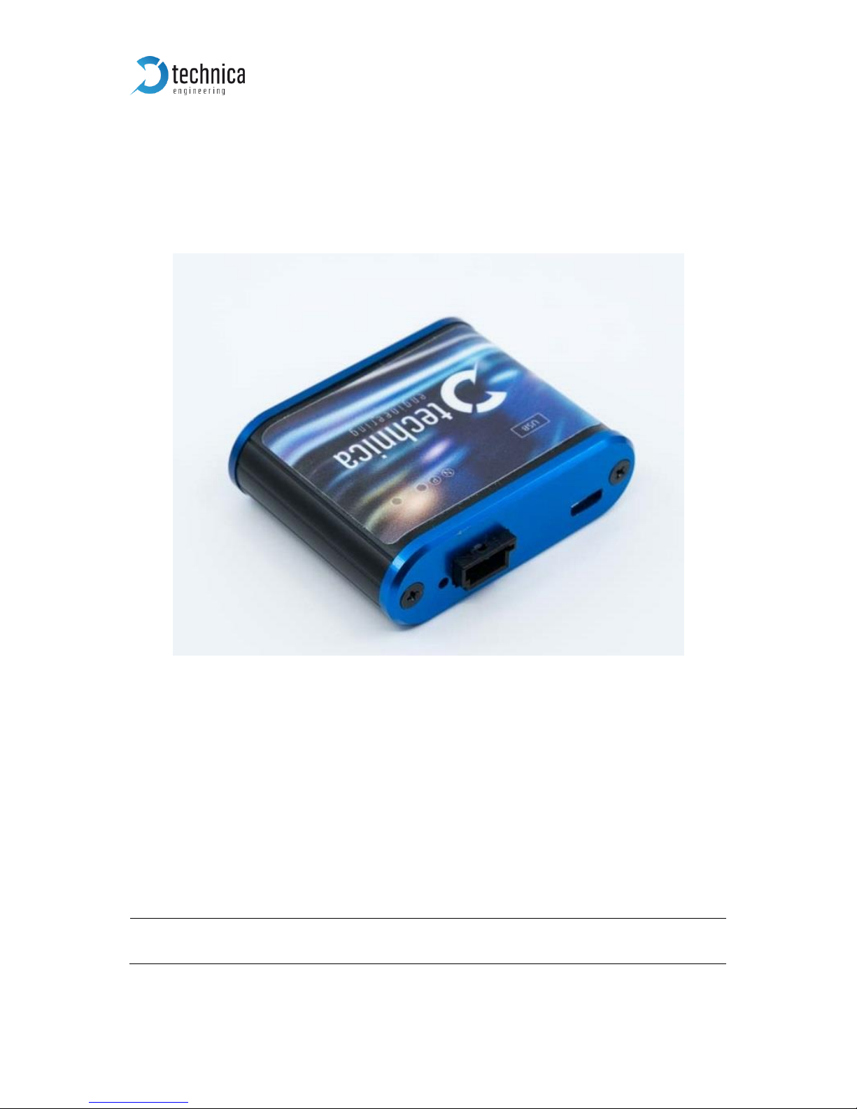
The Technica Engineering USB-100BASE-T1 Converter transmits data frames from
the physical layer BroadR-Reach (100BASE-T1) to USB 2.0.
Features:
• 1 port 100BASE-T1 with Broadcom BroadR-Reach Technology
• 1 port USB 2.0 mini B
• 1 Status LED
General Information:
Power requirement:
5V
Power consumption:
2,5 Watt
Figure 1—1: USB-100BASE-T1 Converter
Page 4

USB-100BASE-T1 Converter User Manual
4
LINKS:
The User can download the latest firmware and documentation for the USB-100BASET1 Converter here:
https://technica-engineering.de/produkt/usb-100base-t1-converter/
1.2 Warranty and Safety Information
Before operating the device, read this manual thoroughly and retain
it for your reference.
The latest documentation for the 100BASE-T1 MediaConverter_BCM
can be downloaded here:
https://technica-engineering.de/produkt/100base-t1mediaconverter_bcm/
Use the device only as described in this manual.
Use only in dry conditions.
Do not apply power to a damaged device.
Do not open the device. Otherwise warranty will be lost.
This device is designed for engineering purpose only.
Special care has to be taken for operation.
Do not use this device in a series production car.
As this device is likely to be used under rough conditions, warranty is
limited to 1 year.
Manufacturer liability for damage caused by using the device is
excluded.
Page 5
USB-100BASE-T1 Converter User Manual
5
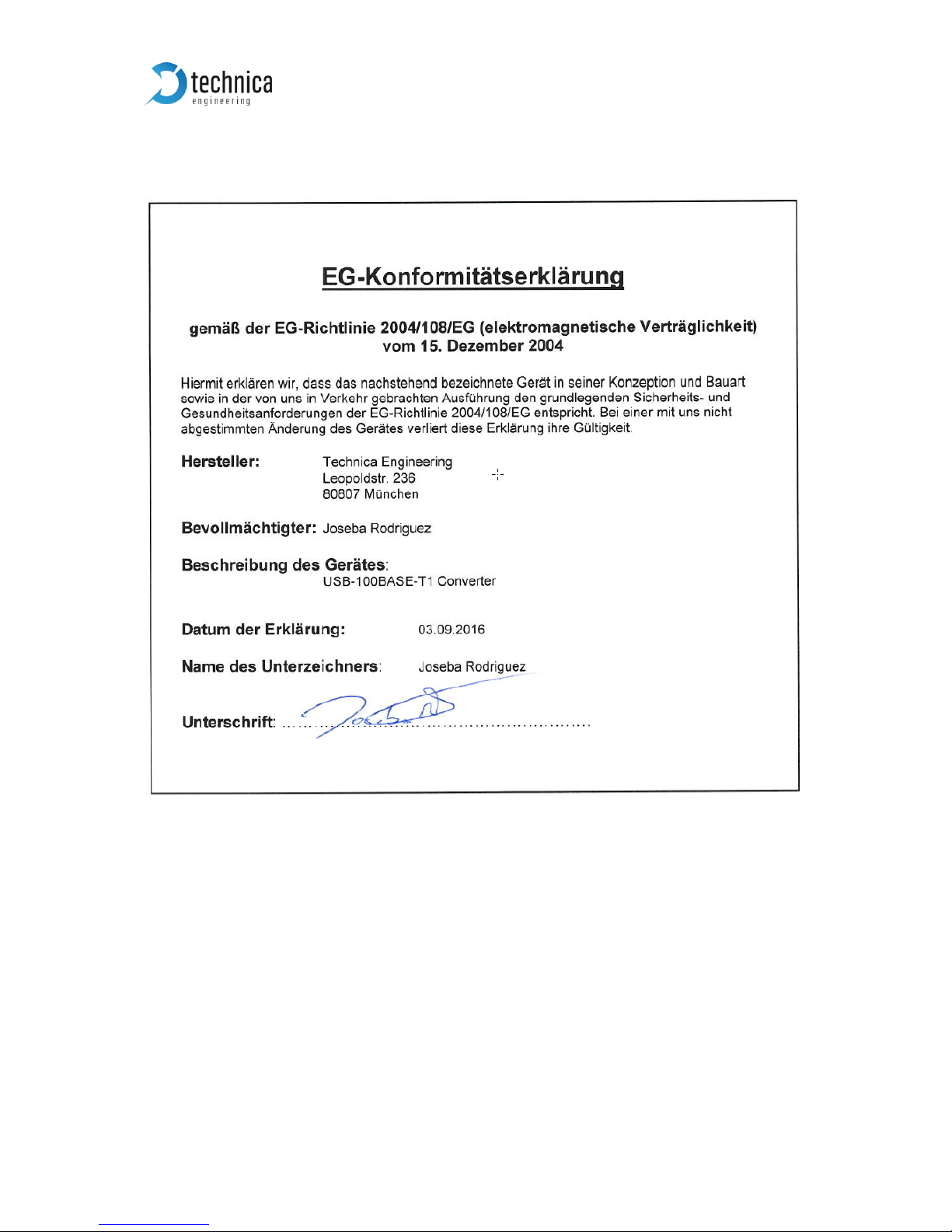
1.3 Declaration of conformity
Figure 1—2: Declaration of conformity
Page 6
USB-100BASE-T1 Converter User Manual
6
2 HARDWARE INTERFACES
2.1 Connectors
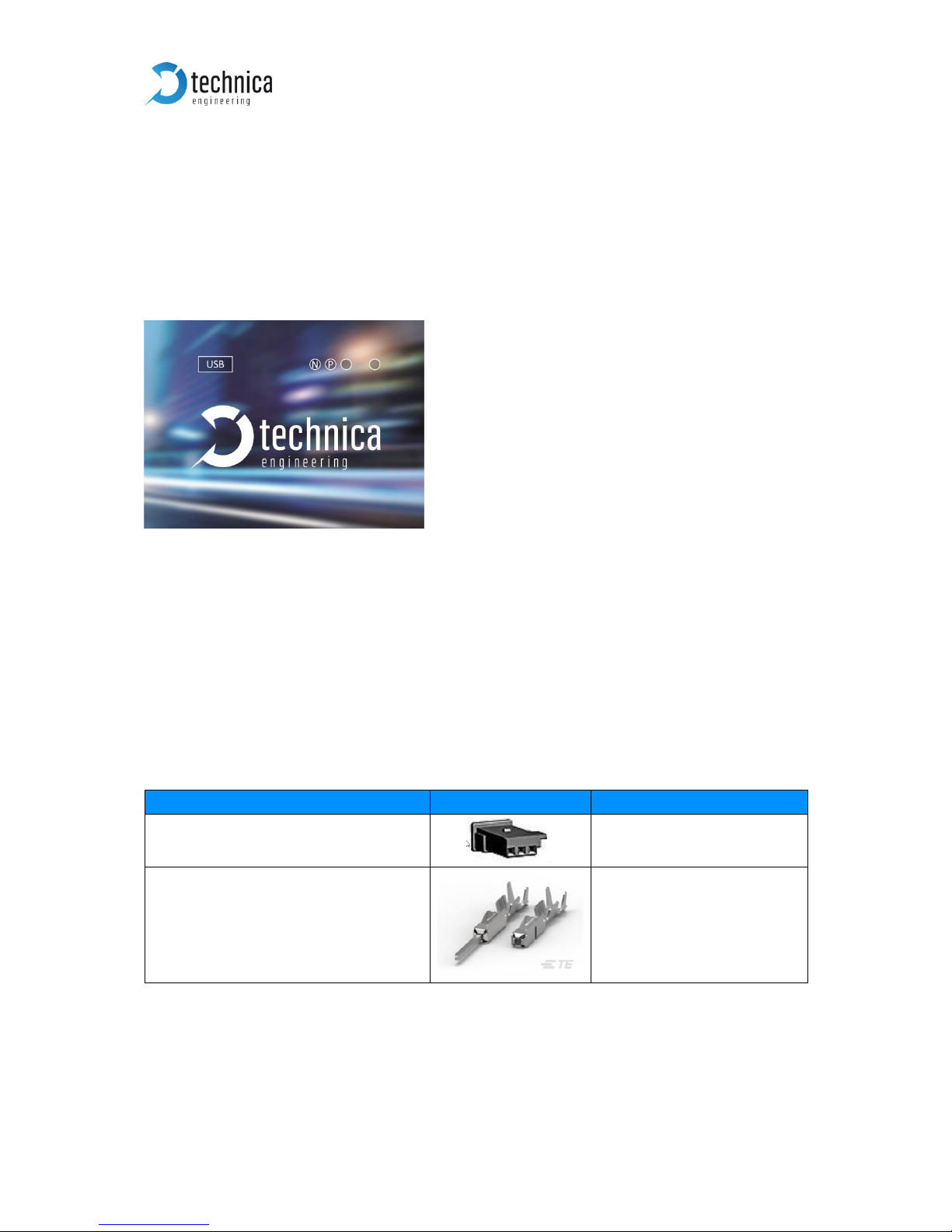
On the label on top of the device you can see an overview about all HW-Interfaces of
the USB-100BASE-T1 Converter.
2.1.1 Black MQS Connector
The pinning of the ECU connectors is listed on the label on top of the device as well.
(See Figure 2—1).
The Connector color is black.
The Tyco Electronics (TE) Micro Quad Lock System (MQS) is used.
Name
Picture
Part Number
Tyco, MQS Buchsengehäuse 3 Pol
4-1718346-1
Tyco crimp contact
928999-1
Table 2—1: Parts of black MQS connector
Note: You can use the official Tyco tool for these crimp contacts. A cheap variant is
the crimp tool for “PSK” contacts.
Figure 2—1: Label of USB-100BASE-T1 Converter with pinning information
Page 7

USB-100BASE-T1 Converter User Manual
7
Pin
Function
1
n.c.
2
100BASE-T1 port, positive
3
100BASE-T1 port, negative
Table 2—2: Pinning of black MQS connector
2.1.2 Universal Serial Bus Connector
There is one USB 2.0 mini B Port for connection to a laptop or PC.
2.2 Other Interfaces
2.2.1 Status LED
The USB-100BASE-T1 Converter has one status LED at the frontside of the case for the
100BASE-T1 Port.
It is lit when there is linkup. It is toggling when there is communication.
Note: There is a bug in the used BroadR-Reach PHY. When the BR Plus and Minus lines
are swapped, and the 100BASE-T1 port is set to Slave then the Link LED is lit, but there
is no data transmission possible. So please connect the 100BASE-T1 lines correctly.
Page 8
USB-100BASE-T1 Converter User Manual
8
3 INSTALLATION
3.1 Driver Installation
A driver is available for following operating Systems:
• Linux x64
• Windows x32
• Windows x64
Download-link
https://technica-engineering.de/produkt/usb-100base-t1-converter/
Please follow the described steps for installation:
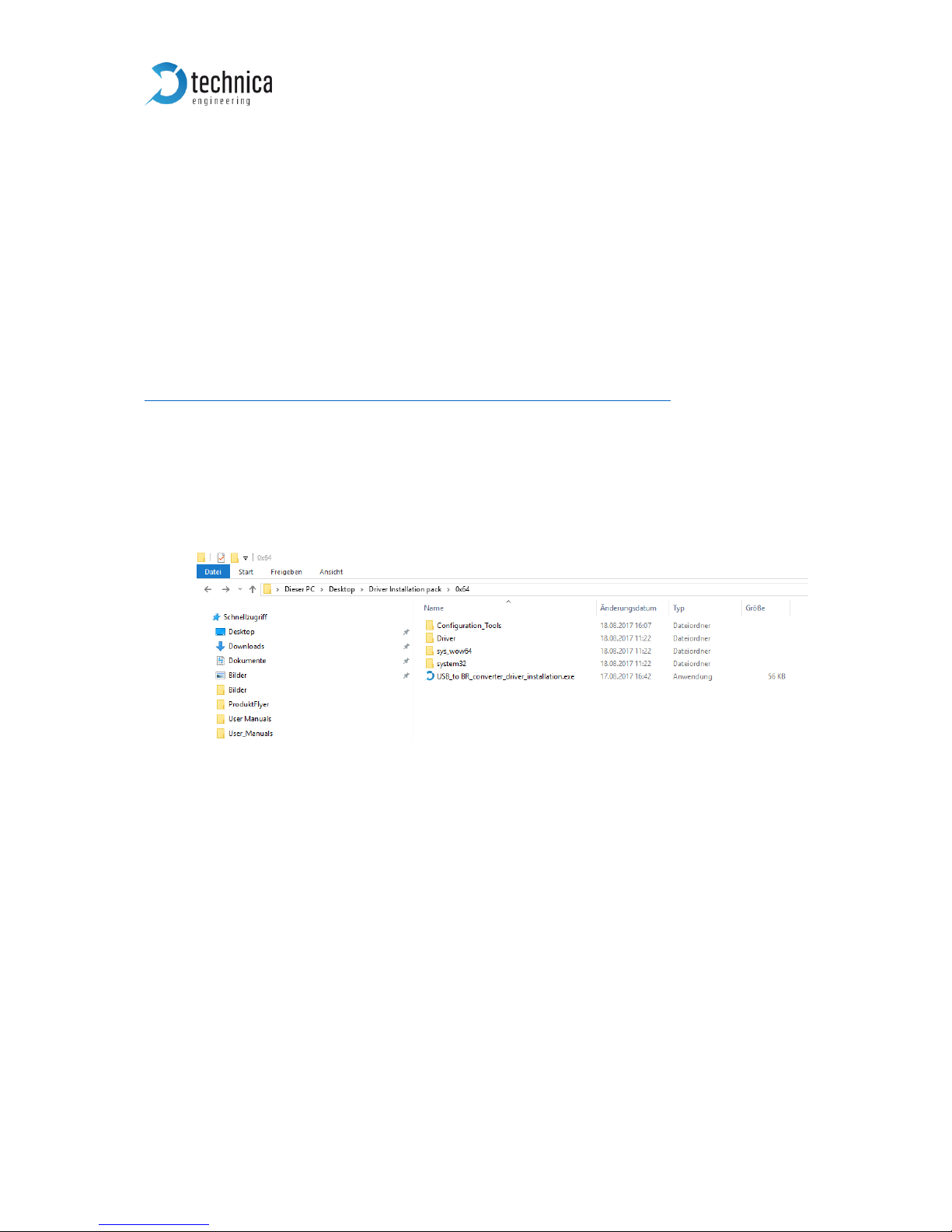
1) Connect your USB-100BASE-T1 Converter device to your computer and browse
your driver installation data folder
Figure 3—1: Driver Installation Data Folder
Page 9
USB-100BASE-T1 Converter User Manual
9
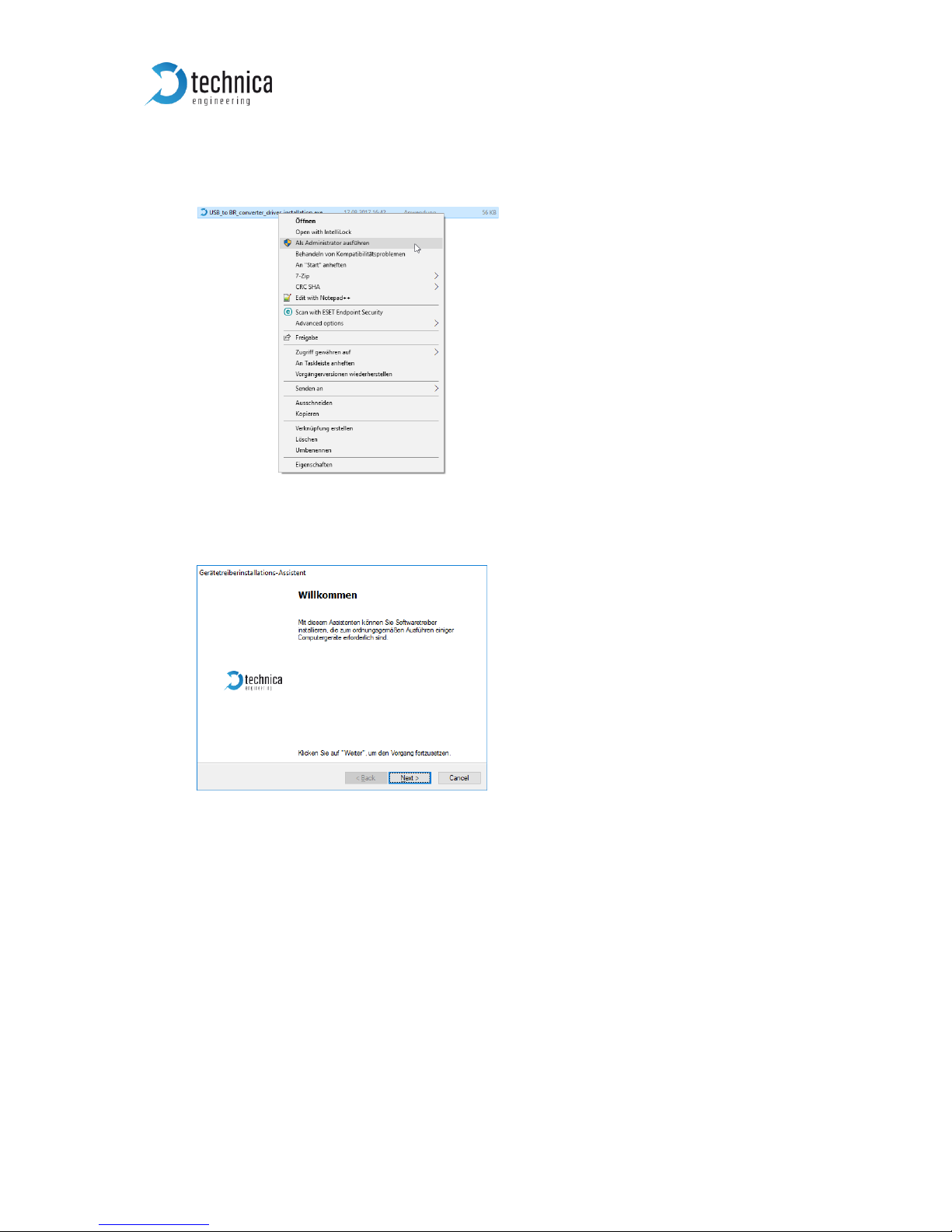
2) Run “USB_to BR_converter_driver_installation.exe” as an administrator, then the
driver installation wizard will appear.
3) Click next to continue installing the driver.
Figure 3—2: Installation as Administrator
Figure 3—3: Start installing the driver
Page 10
USB-100BASE-T1 Converter User Manual
10
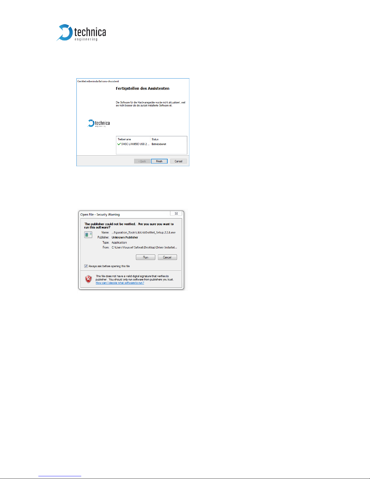
4) At this step the windows drivers are successfully installed. Click Finish to start
installing the LibUsbDotNet library.
5) A window will appear and asking for Installation of the LibUsbDotNet library.
Click Run to start installing the library.
Figure 3—5: Security Warning from Windows
Figure 3—4: Start Installing LibUsbDotNet Library
Page 11
USB-100BASE-T1 Converter User Manual
11
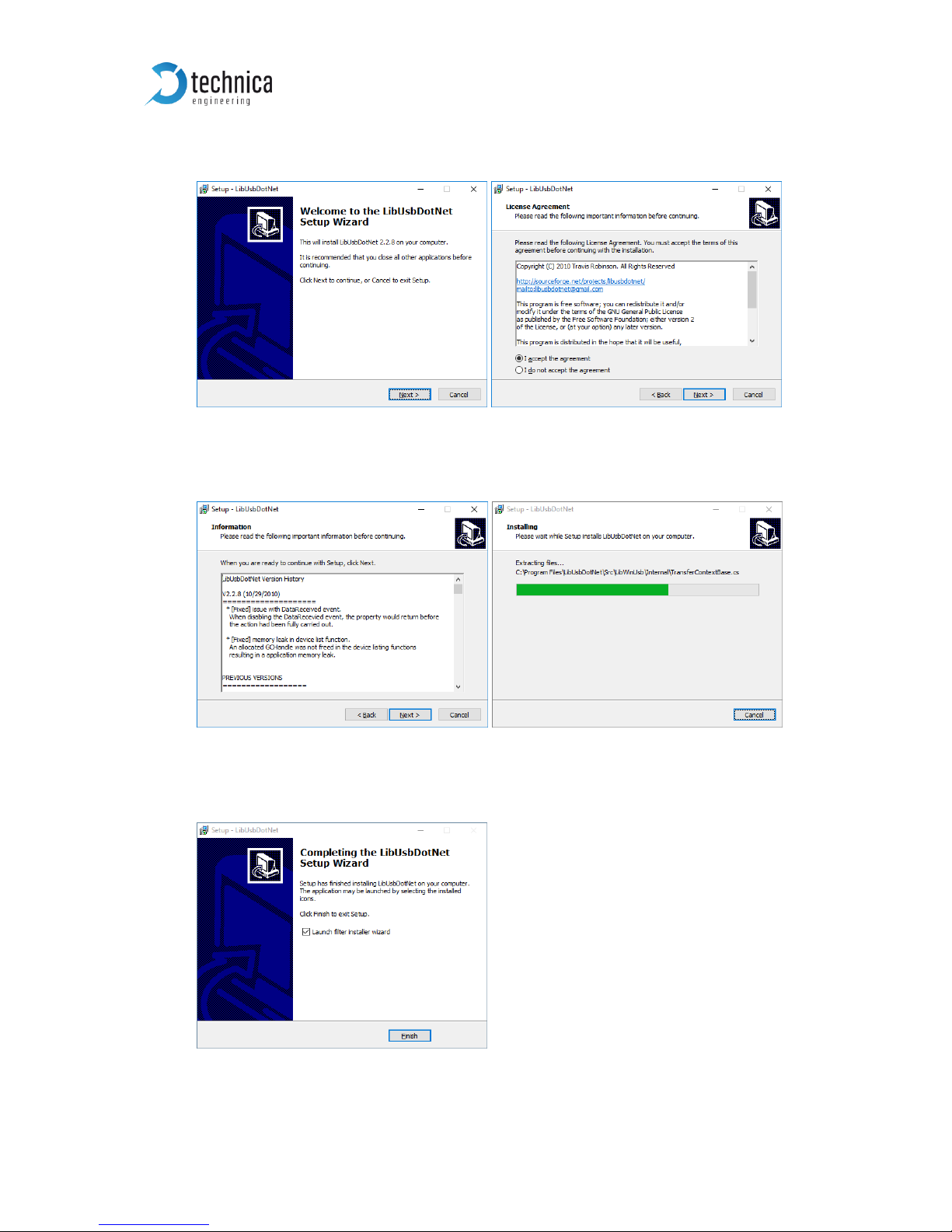
6) Click next to continue installing the LibUsbDotNet library and accept agreement.
7) Click next until the LibUsbDotNet library is installed
8) Click Finish to exit Setup and finish installing the LibUsbDotNet library.
Figure 3—6: LibUsbDotNet Setup Wizard and License Agreement
Figure 3—7: Installation Information
Figure 3—8: Finish of Installation
Page 12
USB-100BASE-T1 Converter User Manual
12
3.2 Device Installation
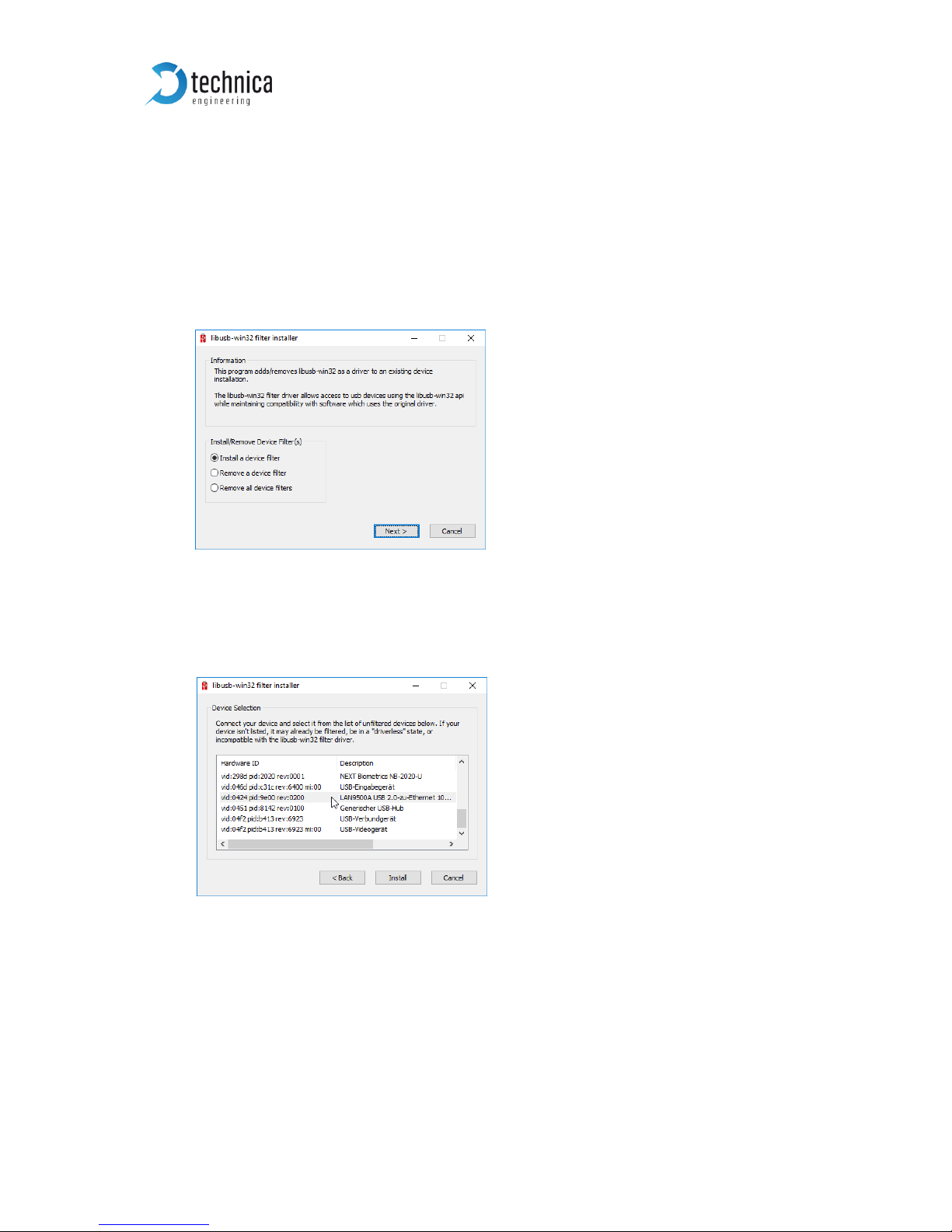
A libusb-win32 filter installer will appear directly after Installation of the driver.
If not, then go to the directory “C:\Program Files (x86)\Technica Engineering\USB to
BR Converter” and run install-filter-win.exe.
1) Select “Install a device filter” to install a device filter for the plugged-in device
then click next (If your device is not plugged-in, click cancel to exit wizard).
2) Select your USB-100BASE-T1 Converter device “LAN9500A USB 2.0 Ethernet
10/100 Adapter” then click Install.
Figure 3—9: Installation of Device Filter
Figure 3—10: Selection of USB-100BASE-T1 Converter Device
Page 13
USB-100BASE-T1 Converter User Manual
13
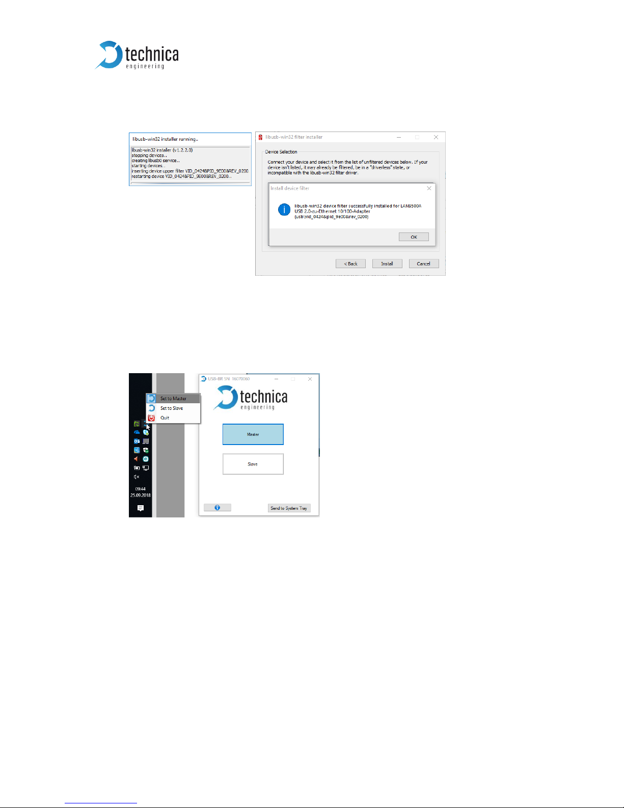
Figure 3—11: Exit of Wizard
3) After successfully installing your device’s filter, click ok then cancel to exit the
wizard.
4) By this time the apllication is installed, if your device is plugged, a system tray
application to configure the USB-BR device should appear in windows system
tray and taskbar.
Figure 3—12: System Tray Icon and Configuration Window
Page 14
USB-100BASE-T1 Converter User Manual
14
3.3 INSTALLATION OF ADDITIONAL DEVICES
If you want to use a further device and you have already installed the drivers, then go
to the directory “C:\Program Files (x86)\Technica Engineering\USB to BR Converter”
and run install-filter-win.exe.
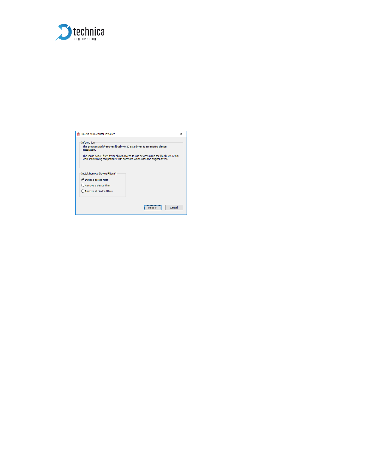
1) The libusb-win32 filter installer window should appear, select “Install a device
filter” and click next.
2) Choose the “LAN9500A USB 2.0 Ethernet 10/100 Adapter” and click install.
Figure 3—13: Installation of Device Filter
Page 15
USB-100BASE-T1 Converter User Manual
15
4 CONFIGURATION
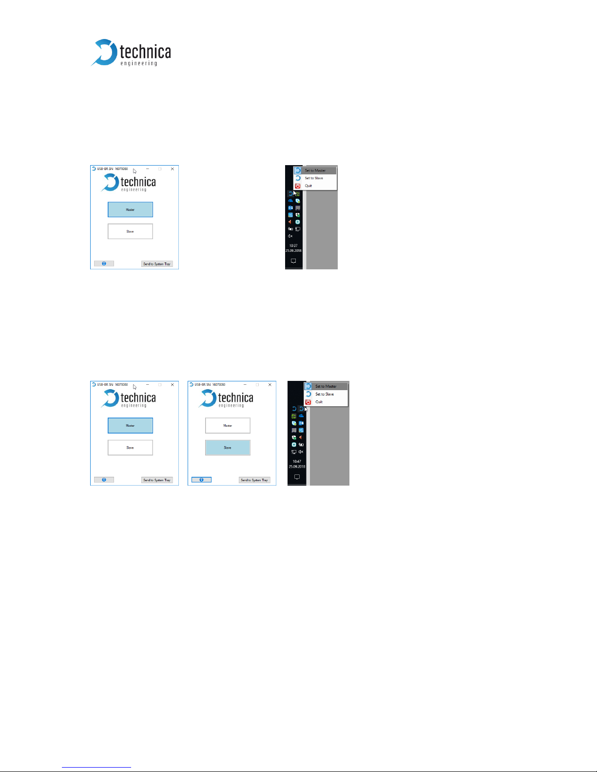
The USB-100BASE-T1 Converter is configured by using the Configurator window or
using directly the system try icon.
Figure 4—1: Configurator or System Tray Application
Every time a device is plugged the System Tray Application will appear in Windows
system tray.
Every device’s System Tray Application will be linked to a certain device using the
device’s serial number, so if you are using multiple devices every device will have its
own system- tray configurator tagged with a different serial number.
Figure 4—2: Two Devices (One Master, One Slave) and two Tray Icons
The Configurator tool can be used to configure the USB-BR device to work in two
modes either as a Master or Slave.
Note: The Device is initially configured to work as a Master.
Note: In a BroadR-Reach Link one device must be set as Master, the other must be set
as Slave.
Page 16

USB-100BASE-T1 Converter User Manual
16
Configuration Options:
• The “Master” button can be used to configure the BroadR-Reach port to work in
Master mode.
• The “Slave” button can be used to configure the BroadR-Reach port to work in
Slave mode.
• The “Send to System Tray” button can be used to hide the configurator window
and send it to the windows system tray.
• The “information” button can be used to open this help!
Note: The windows application used to control the system-tray application is installed
in windows startup folder
“AppData\Roaming\Microsoft\Windows\Start Menu\Programs\Startup”
in order to run this application whenever windows starts.
If this is not desired then you can also start this application by running “Program Files
(x86)\Technica_Engineering\USB_to_BR_Converter\USB_to_BR_config_tool.exe”.
Please also make sure the USB_to_BR_config_tool.exe instance in the Windows
Startup is not running!
Page 17

USB-100BASE-T1 Converter User Manual
17
5 ADDITIONAL INFORMATION
• The maximum cable length for BroadR-Reach segments is limited to 15 meters.
Page 18

USB-100BASE-T1 Converter User Manual
18
6 LIST OF FIGURES
Figure 1—1: USB-100BASE-T1 Converter .......................................................................... 3
Figure 1—2: Declaration of conformity ............................................................................. 5
Figure 2—1: Label of USB-100BASE-T1 Converter with pinning information ................. 6
Figure 3—1: Driver Installation Data Folder ...................................................................... 8
Figure 3—2: Installation as Administrator ......................................................................... 9
Figure 3—3: Start installing the driver ............................................................................... 9
Figure 3—4: Start Installing LibUsbDotNet Library ......................................................... 10
Figure 3—5: Security Warning from Windows ................................................................ 10
Figure 3—6: LibUsbDotNet Setup Wizard and License Agreement .............................. 11
Figure 3—7: Installation Information ............................................................................... 11
Figure 3—8: Finish of Installation .................................................................................... 11
Figure 3—9: Installation of Device Filter .......................................................................... 12
Figure 3—10: Selection of USB-100BASE-T1 Converter Device .................................... 12
Figure 3—11: Exit of Wizard ............................................................................................. 13
Figure 3—12: System Tray Icon and Configuration Window ......................................... 13
Figure 4—1: Installation of Device Filter .......................................................................... 14
Figure 5—1: Configurator or System Tray Application .......................................... 15
Figure 5—2: Two Devices (One Master, One Slave) and two Tray Icons ...................... 15
Page 19

USB-100BASE-T1 Converter User Manual
19
7 CHANGELOG
Version
Chapter
Description
Date
1.0
All
First release
2.0
All
Rework of design and update of all information
25.09.2018
Page 20

USB-100BASE-T1 Converter User Manual
20
8 CONTACT
If you have any questions regarding this product, please feel free to contact us:
Technica Engineering GmbH
Leopoldstr. 236
80807 München
Germany
Fax: +49-89-34290265
www.technica-engineering.de
 Loading...