

Page 1
1
Introduction
Dear Customer,
Your Pedelec has been carefully pre-assembled
in the factory. For easier transport, some parts
have been loosened and put in transport position. In order to get the Pedelec ready and safe to
ride, these parts must be put into a normal position and fastened after the Pedelec is unpacked.
Let a specialist perform these worksteps. They are relevant for your
safety.
However, the resulting costs are not born by
the manufacturer!
If you would like to do this work yourself, be sure
to read these instructions carefully and keep it
safely. Follow all of the steps it describes.
Let a specialist dealer install the fol-
lowing parts correctly: lighting
equipment, all reectors, the bell,
protectors for chainring and spokes. Without
those parts your pedelec does not conform
to German legal requirements and applicable standards. Only fully equipped it is legal
to ride on public roads in Germany and many
other countries. Inform yourself about the
applicable laws in your country and region.
These assembly instructions are applicable only
together with the included operating instructions.
Page numbers refer to the pages of the original
operating instructions.
Safety Instructions
This operating manual contains ve dierent
types of pointers – one providing important information about your new Pedelec and how to
use it, a second referring to possible damage to
property and the environment, and a third type
warning against potential falls and serious damage, including physical injury. The fourth pointer
prompts you to apply the proper torque so the
parts don't loosen or break. The fth pointer reminds you that it is necessary to study the operation and installation manuals included carefully.
When you see these symbols, there is always a
risk that the described danger may occur.
The text which the warning covers always has a
grey background.
The warnings break down as follows:
Note
This symbol provides information about how to use the prod-
uct or highlights specic parts of
the operating instructions that are particularly important.
Attention
This symbol warns of misuse
which could result in damaging
the product or the environment.
Danger
This symbol indicates possible
dangers to your health and life
that could arise if specic ac-
tions or apopropriate care is not taken.
Important bolted connection
Precise torque must be applied
here when tightening. The cor-
rect mounting torque is either
displayed on the component or listed in the
table of torques in he chapter on bolted connections. In order to apply a precise torque,
you must use a torque wrench. If you don't
have a torque wrench, refer this work to a
specialist dealer! Parts which do not have
the correct torque could fall o or break! This
may result in severe falls.
Operating instructions
Read all of the instruction manu-
als delivered with the bicycle. If
you are unsure about any of the
topics addressed in this handbook, contact
your specialist dealer or service partner.
Modern Pedelec technology is hightech! Working on bicycle parts
therefore requires expert knowledge, experience and specialist tools! Do not
work on your Pedelec by yourself. Take your
Pedelec to a specialist workshop if it is in
need of repair, maintenance or restoration.
ASSEMBLY INSTRUCTIONS
TECHNIBIKE
E-CITY/E-TREKKING/E-MTB
City bike/trekking bike/ATB/MTB ISO 4210:2014 Pedelec/E-Bike EN 15194
ENGLISH
Article number 731-00232
Page 2
2
Intended Use
Not every Pedelec can be used everywhere and for every purpose. Be-
fore riding, be sure to read the information in the “Intended Use” section of the
original operating instructions. If you are not
clear about what type of Pedelec you have
and how it should be used, contact your specialist dealer or service partner.
Unpacking the Pedelec
The Pedelec is shipped in a special closed shipping carton. Find a suitable space for performing
the assembly.
The vehicle has had lubricants ap-
plied at various locations. Always
wear appropriate clothing and personal protective equipment, such as suitable gloves, when assembling.
The carton may be heavy.
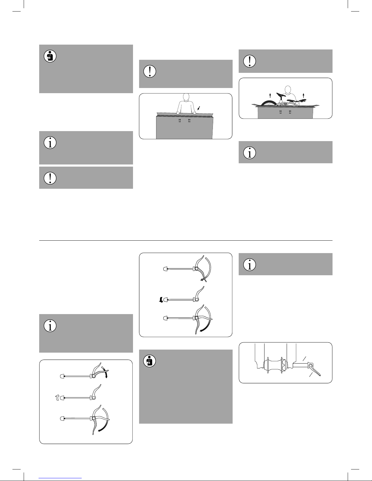
1. Place the shipping carton upright on its bottom side. This side can be found using the
printing on the cartons. Then open it on the
top.
Be careful; metal staples may have
been used to close the carton. Take
care not to injure yourself on these
staples.
TOP
Open the cover.
The shipping carton also contains boxes of accessories containing:
• pedals with reectors mounted
• lighting system in accordance with the german
laws
• bell
• spoke reektors
• protectors for chainrings and spokes
• charging device for the battery
• all manuals
2. Lift the Pedelec and the box of accessories
carefully out of the shipping carton.
The vehicle may be heavy. Get help
from another person.
Lift the bicycle out.
TOP
3. Check if your Pedelec has been damaged in
transport.
Dispose of the packaging material
properly and according to regulations at an appropriate disposal site.
Operating Quick Releases and
Quick Release Axles
Quick releases are systems used in place of
bolted connections to attach parts to the Pedelec. They consist of two parts: the clamping
lever, which provides the necessary clamping
force, and the locking nut, which allows you to
regulate the clamping force. You can change the
setup of your quick release when the clamping
lever is open.
Quick releases should be closed
with the correct holding force. To
close the lever correctly, pressure
should be felt when it is half closed and, at
the end, the ball of the thumb needs to be
used to completely close it.
Loosening the adjusting nut
Tightening the adjusting nut
• All quick releases and quick re-
lease axles must be rmly closed
before you set o.
• Make sure all quick releases and quick release axles are securely and properly fastened - even if the Pedelec has only been
left unattended for a short time.
• A closed quick release fastener must be
folded close to the frame, fork or seat post.
• In a closed state, the tip of the quick release lever must always be pointed backwards. This way, the quick release won’t
open during the ride.
Secure wheels or other parts of your
Pedelec that are attached with quick
releases when you park your bicycle.
In current chassis, quick release axles may be
used in place of quick releases or bolts. These
usually function like quick releases and must be
operated as such.
The axle is attached or screwed into the dropout and holds the hub between the two dropouts.
The hub and the axle may be fastened with a
quick release lever, which is operated just like a
normal quick release. Systems in which the axle
is only inserted or screwed in and then fastened
with a screw also exist.
Quick release axle
Quick release lever
Please read the enclosed instructions of the
parts manufacturer on this topic and contact
your specialist dealer or service partner
should you have questions regarding the system.
Page 3
3
Adjusting the Saddle Height
To adjust the saddle and seat position correctly and safely, please refer
to the information in the original operating instructions which can be found in the
chapter “Adjusting the bicycle to the rider”.
The seat post has been folded for transport.
Open the quick release or loosen the Allen key
on the seat post clamp and pull the seat post
into the suitable position.
Please note that the saddles of Pedelecs that
are equipped with a hydraulic or spring-operated
seat post may sink a little after you have mounted
them. This changes the seat position.
Once you have found a suitable seat position,
close the quick release again or tighten the
screw of the seat post clamp again.
The seat post has a minimum lowering depth that
can be found at the bottom end of the seat post. If
it is exceeded, there is risk of breakage.
Assembly
After assembly and adjustments are
complete, be sure to check that all
screw connections and fas-
teners are securely xed.
The vehicle has had lubricants applied at various
locations. Always wear appropriate clothing and
personal protective equipment, such as suitable
gloves, when assembling.
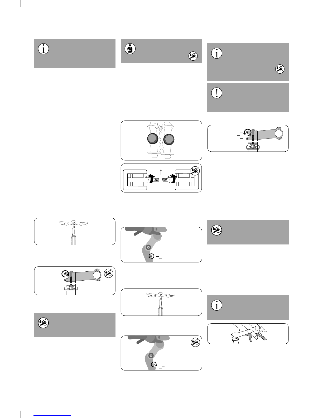
Assembling the Pedals
The pedals are marked “L” for “left” and “R” for
“right”. Turn the right pedal into the crank arm on
the chainring side and the left pedal on the opposite side.
L
R
Forwards
Apply assembly grease to both threads before
installing the pedals.
Note that the right pedal must be
turned clockwise, while the left ped-
al must be turned counterclockwise.
To do this, use an open-end wrench, an Allen key or a special long pedal
wrench. The appropriate tightening
torque is 40 Nm.
If the pedals are mixed up or cross-
threaded, the threads will be dam-
aged. The pedals could break o
from the crank, which can lead to a crash
and severe injuries.
A-Head Stem
Stem
clamping screw:
1. Loosen the stem clamping screw of the stem
with a 5 mm hex key, turning counter-clockwise. Back it out only a few turns.
2. Align the stem so that the handlebars are at
exactly a 90 degree angle, perpendicular to
the front wheel.
Stem
clamping
screws
3. Now use a torque wrench to tighten the stem
clamping screws clockwise.
An A-head stem must be tightened
to 6 – 8 Nm. If a dierent tightening
torque is marked on the component,
use that torque instead.
Adjustable A-Head Stem
Stem clamping screw
1. Loosen the stem clamping screw on the bottom of the stem with a 5 mm hex key, turning counter-clockwise. Back it out only a few
turns.
2. Align the stem so that the handlebars are at
exactly a 90 degree angle, perpendicular to
the front wheel.
Stem clamping screw
3. Now use a torque wrench to tighten the stem
clamping screws clockwise.
An A-head stem must be tightened
to 10 – 12 Nm. If a dierent tightening torque is marked on the compo-
nent, use that torque instead.
Information on adjusting an adjustable stem can
be found in the chapter “Adjusting the bicycle to
the rider” and possibly also in the enclosed instructions of the parts manufacturer.
Brake Levers
Set up your brake levers in such a way that you
can safely apply them and brake comfortably.
The brake levers should be set up
so that your hands can apply them
as a straight extension of your
arms.
90°
90°
Page 4
4
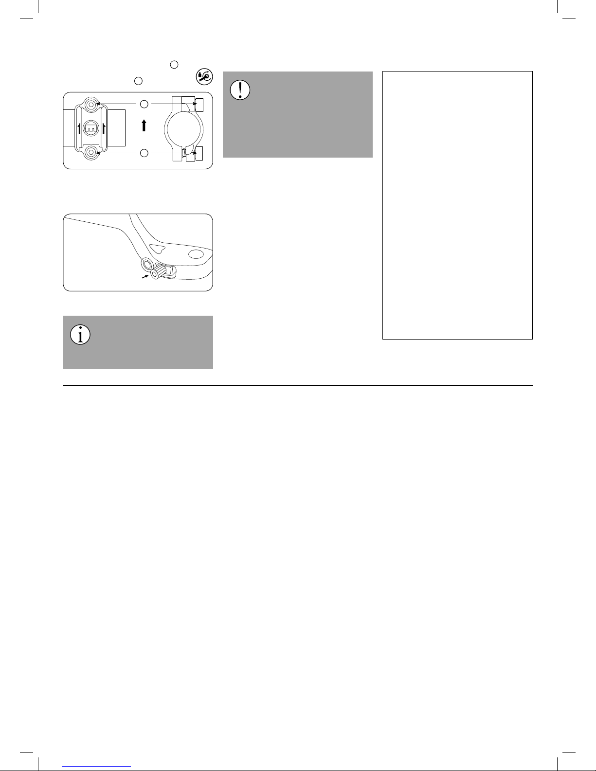
Once the brake levers are in a position which
suits you, rst tighten the top screw
1
of the clam
bracket of the brake lever to 4 Nm. Then
tighten the lower screw
2
to 4 Nm as well.
Top
1
2
The distance to the handlebars can be adjusted
with an adjusting screw (in the levers) so that the
brake levers can be safely operated by hands of
diering sizes.
Adjusting screw
Inserting the Battery
The operating instructions of the
drive system from Continental are
enclosed with your Pedelec. To insert the battery, follow the instructions in this
manual.
Testing
Perform the following test before the
rst ride: Lift your Pedelec up slight-
ly and drop it onto the ground from
about 10 cm in the air. If you hear rattling or
other unusual noises, check all bolted connections. If rattling or unusual noises persist
even after you have checked, have a spe-
cialist dealer or service partner determine
and remove the cause before you set o.
Now perform the check from the section “Before
your rst ride” in the original operating instructions.
Legal information
TechniBike GmbH
Julius-Saxler-Straße 3, TechniPark
D-54550 Daun / Germany
Fax +49 6592 712 8219
Contact: [email protected]
Website: www.technibike.de
Management: Peter Lepper,
Marc A. Prüm, Claudia Thelen
Responsible for distributing and marketing the operating instructions
inMotion mar.com, Rosensteinstr. 22,
D-70191 Stuttgart / Germany
Tel. +49 711 35164091, Fax +49 711
35164099
[email protected], www.inmotionmar.com
Content and images
Veidt-Anleitungen, Friedrich-Ebert-Straße 32
D-65239 Hochheim/Germany
[email protected]
Legal inspection by a lawyer’s oce specialising in intellectual property.
This operating manual covers the requirements and scope of ISO 4210:2014 and
EN 15194.
In case of delivery and use outside this
scope, the manufacturer of the vehicle must
supply the requisite manuals.
© Before reproducing, reprinting, translating or using this document for any economic
purpose (even in part, printed or electronic
form), you must rst receive written consent.
TechniBike Installation Version 1.0 January 2018
 Loading...