

Technibel SPAFP 124 R, CAFP 484 R, SPAFP 255 R, SPAFP 365 R, SPAFP 485 R Instruction Manual
...Page 1

Pub. OI-85464189722000
© 2005
Save These Instructions!
Conserver ce mode d’emploi
Bewahren Sie bitte diese
Bedienungsanleitung auf.
Conservate queste istruzioni
Guarde estas instruções
Φυλάξτε τις οδηγίες αυτές
Guarde estas instrucciones
Split System Air Conditioner
Climatiseur Split System
Split-System-Klimagerät
Condizionatore d’Aria Split
Aparelho de Ar Condicionado Sistema Split
Κλιµατιστικ ∆ύο Μονάδων
Acondicionador de Aire de Dos Unidades
•
INSTRUCTION MANUAL
•
MODE D’EMPLOI
•
BEDIENUNGSANLEITUNG
•
ISTRUZIONI PER L’USO
•
MANUAL DE INSTRUÇÕES
• ΕΓΧΕΙΡΙ∆ΙΟ Ο∆ΗΓΙΩΝ
•
MANUAL DE INSTRUCCIONES
This air conditioner uses the new refrigerant R410A.
SEMI-CONCEALED CEILING-MOUNTED WALL-MOUNTED CONCEALED DUCT
(4-WAY)
CAFP 124 R
CAFP 164 R
CAFP 184 R
CAFP 254 R
CAFP 364 R
CAFP 484 R
SPAFP 124 R
SPAFP 164 R
SPAFP 184 R
SPAFP 255 R
SPAFP 365 R
SPAFP 485 R
MAFP 125 R
MAFP 165 R
MAFP 185 R
MAFP 225 R
(Standard Static Pressure)
DSAFP 124 R
DSAFP 164 R
DSAFP 184 R
DSAFP 255 R
DSAFP 365 R
DSAFP 485 R
Page 2

2
Contents
Page
Product Information........................................................................................... 2
Alert Symbols .................................................................................................... 2
Installation Location .......................................................................................... 3
Electrical Requirements .................................................................................... 3
Safety Instructions............................................................................................. 3
Names of Parts (Indoor Unit) ............................................................................ 4
Wireless Remote Control Unit (Optional parts) ................................................. 5
Parts Name and Functions .......................................................................... 5
Receiver....................................................................................................... 8
Operation ..................................................................................................... 9
Using the Wireless Remote Control Unit ................................................... 11
Address Settings........................................................................................ 13
Emergency Operation ................................................................................ 15
Troubleshooting.......................................................................................... 17
Wired Remote Control Unit (Optional parts) ................................................... 18
Parts Name and Functions ........................................................................ 18
Display ....................................................................................................... 21
Operation ................................................................................................... 22
Adjusting the Airflow Direction ........................................................................ 24
Adjusting the Airflow Direction for Multiple Indoor Units Using a Single Remote
Control Unit ..................................................................................................... 27
Special Remarks ............................................................................................. 28
Setting the Timer............................................................................................. 29
Care and Cleaning .......................................................................................... 31
Troubleshooting............................................................................................... 33
Tips for Energy Saving.................................................................................... 33
Product Information
If you have problems or questions concerning your Air Conditioner, you will
need the following information. Model and serial numbers are on the nameplate
on the bottom of the cabinet.
Model No. ______________________ Serial No. ____________________
Date of purchase ________________________________________________
Dealer’s address ________________________________________________
Phone number ________________
DECLARATION OF CONFORMITY
This product is marked « » as it satisfies EEC Directive No. 89/336/EEC, 73/
23/EEC and 93/68/EEC, and conforms with following standards.
This declaration will become void in case of misusage and/or from non
observance though partial of Manufacturer’s installation and/or operating
instructions.
Note: This air conditioner uses the new refrigerant R410A.
Alert Symbols
The following symbols used in this manual, alert you to potentially
dangerous conditions to users, service personnel or the appliance:
This symbol refers to a hazard or unsafe
practice which can result in severe personal
injury or death.
This symbol refers to a hazard or unsafe
practice which can result in personal injury
or product or property damage.
CAUTION
OI-722-2-EG
01_Technibel-PACi_EN.fm Page 2 Thursday, December 9, 2004 11:36 AM
Page 3

3
Installation Location
• We recommend that this air conditioner be installed properly by
qualified installation technicians in accordance with the Installation
Instructions provided with the unit.
• Before installation, check that the voltage of the electric supply in your home
or office is the same as the voltage shown on the nameplate.
Electrical Requirements
1. All wiring must conform to the local electrical codes. Consult your dealer or a
qualified electrician for details.
2. Each unit must be properly grounded with a ground (or earth) wire or
through the supply wiring.
3. Wiring must be done by a qualified electrician.
Safety Instructions
• Read this Instruction Manual carefully before using this air
conditioner. If you still have any difficulties or problems, consult your
dealer for help.
• This air conditioner is designed to give you comfortable room
conditions. Use this only for its intended purpose as described in this
Instruction Manual.
• Do not install this air conditioner where there are fumes or flammable
gases, or in an extremely humid space such as a greenhouse.
• Do not install the air conditioner where excessively high heatgenerating objects are placed.
Avoid: To protect the air conditioner from heavy corrosion, avoid installing the
outdoor unit where salty sea water can splash directly onto it or in
sulphurous air near a spa.
To warm up the system, the power mains must
be turned on at least five (5) hours before
operation. Leave the power mains ON unless
you will not be using this appliance for an
extended period.
• Never touch the unit with wet hands.
• Never use or store gasoline or other flammable vapor or liquid near
the air conditioner — it is very dangerous.
• This air conditioner has no ventilator for intaking fresh air from
outdoors. You must open doors or windows frequently when you
use gas or oil heating appliances in the same room, which consume
a lot of oxygen from the air. Otherwise there is a risk of suffocation
in an extreme case.
• Do not turn the air conditioner on and off from the power mains
switch. Use the ON/OFF operation button.
• Do not stick anything into the air outlet of the outdoor unit. This is
dangerous because the fan is rotating at high speed.
• Do not let children play with the air conditioner.
• Do not cool or heat the room too much if babies or invalids are present.
CAUTION
Power mains
ON
CAUTION
OI-722-3-EG
01_Technibel-PACi_EN.fm Page 3 Thursday, December 9, 2004 11:36 AM
Page 4

4
Names of Parts (Indoor Unit)
INDOOR UNIT
SEMI-CONCEALED
CAFP type (4-WAY)
DSAFP type (standard static pressure)
CONCEALED DUCT
Water drain
Flexible duct
(optional)
Canvas duct
(optional)
Air intake grille
(air intake)
(optional)
Air outlet grille
(optional)
Water drain
Ceiling panel
(optional)
Air outlet
(4 locations)
Air intake grille
(air intake)
CEILING-MOUNTED
SPAFP type
WALL-MOUNTED
MAFP type
Wate r dr ain
(You can
connect the
drain pipe
either the right
or left side.)
Air intake
grille (air
intake)
Air intake
Air outlet
Air outlet
REMOTE CONTROL UNITS
(Wired type: available for
all indoor units)
(Wireless type: available
for all indoor units)
OI-722-4-EG
01_Technibel-PACi_EN.fm Page 4 Thursday, December 9, 2004 11:36 AM
Page 5

5
Wireless Remote Control Unit
(Optional parts)
Parts Name and Functions
The illustration above pictures the wireless remote control unit after the cover
has been lowered and removed.
A: ON/OFF operation button This button is for turning the air conditioner on and off.
B: Transmitter When you press the buttons on the wireless remote control unit, the mark
appears in the display to transmit the setting changes to the receiver in the
air conditioner.
C: MODE button Use this button to select one of the following five operating modes.
(AUTO) : Used to automatically set cooling or heating operation. Only for single
heat pump type
(temperature range: 17 to 27°C)
(HEAT) : Used for normal heating operation. Only for heat pump type
(temperature range: 16 to 26°C)
(DRY) : Used for dehumidifying without changing the room temperature.
(temperature range: 18 to 30°C)
(COOL) : Used for normal cooling operation.
(temperature range: 18 to 30°C)
(FAN) : Used to run the fan only, without heating or cooling operation.
D: Temperature setting
buttons
: Press this button to increase the temperature setting.
: Press this button to decrease the temperature setting.
E: FAN SPEED selector button
(AUTO)
(HI.)
(MED.)
(LO.)
: The air conditioner automatically decides the fan speeds.
: High fan speed
: Medium fan speed
: Low fan speed
I: FLAP button
Q: Slide switch
L: SET button
P: ACL button
(ALL CLEAR)
A: ON/OFF operation button
B: Transmitter
D: Temperature setting buttons
H: A/C SENSOR button
N: VENTILATION button
J: TIMER SET button
O: Remote control sensor
F: FILTER button
K: Time setting buttons
G: ADDRESS button
E: FAN SPEED selector button
M: CL button
C: MODE button
NOTE
OI-722-5-EG
01_Technibel-PACi_EN.fm Page 5 Thursday, December 9, 2004 11:36 AM
Page 6

6
Parts Name and Functions (continued)
F: FILTER button If a separately installed signal receiver is being employed, this button is used
to turn off its filter lamp. When the filter lamp has lighted, first clean the filter,
and then press the FILTER button to turn off the filter lamp.
When a wired remote control unit and wireless remote control unit are both
used, the filter sign on the wired remote control unit will be appeared. When
this happens, first clean the filter, and then press the FILTER button on one
of the remote control units to turn off the filter sign.
G: ADDRESS button When a multiple number of indoor units that can be operated by the wireless
remote control unit have been installed in the same room with a multi-unit or
single-unit installation, this button enables addresses to be set in order to
prevent the sending of signals to the wrong indoor unit. Each of up to six
indoor units can be controlled separately using its own wireless remote
control unit by matching the number of the address switch on the operation
area of the indoor unit and the number used for the address of its remote
control unit. (The indoor units cannot be controlled separately when they are
used in a flexible combination format, simultaneous operation of multi units
format or any other such format since they will all operate at the same time.)
When the batteries are replaced, the address setting returns to “ALL”, and so
please make the setting again.
H: A/C SENSOR button When you press this button (use a small-tipped object such as a ballpoint
pen), the indication will disappear at the display. And the room
temperature is detected by the sensor which is built in the indoor unit and the
air conditioner is controlled accordingly.
If the remote control is located near a heat source, such as a space heater or
in direct sunlight, press the A/C SENSOR button to switch to the sensor on
the indoor unit.
I: FLAP button 1. Use this button to set the airflow direction to a specific angle.
The airflow direction is displayed on the remote control unit.
Operation mode
Number of airflow direction settings
(COOL) or (DRY) 3
(HEAT) or (FAN) 5
(AUTO)
Cooling mode: 3
Heating mode: 5
• In the cool mode and dry mode, if the flaps are set in a downward
position, condensation may form and drip around the vent.
• Do not move the flap with your hands.
This function is available for models CAFP, SPAFP and MAFP.
(SWEEP) 2. Use this button to make the airflow direction sweep up and down
automatically.
Press this button several times until the symbol appears on the
display.
To stop the swing operation
Press the FLAP button again during the flap swing operation to stop the flap
at the desired position. Then, the airflow can be set from the top position by
pressing the FLAP button again.
NOTE
NOTE
CAUTION
NOTE
OI-722-6-EG
01_Technibel-PACi_EN.fm Page 6 Thursday, December 9, 2004 11:36 AM
Page 7

7
Parts Name and Functions (continued)
Indicator when swing operation is stopped
During cooling and drying, the flap does not stop at the downward position.
Even if the flap is stopped at the downward position during the swing
operation, it does not stop until it moves to the third position from the top.
This function is available for models CAFP, SPAFP and MAFP.
J: TIMER SET button
(OFF Timer)
(OFF Cycle Timer)
(ON Timer)
Use this button while the unit is operating to switch between timer settings.
: The air conditioner stops after a preset time elapses.
:The air conditioner always stops after a preset time elapses.
: The air conditioner starts after a preset time elapses.
K: Time setting buttons : Press this button to increase the time.
: Press this button to decrease the time.
L: SET button Use this button to set the timer.
M: CL button Use this button to clear the timer setting.
N: VENTILATION button This is used when a ventilation fan (available commercially) is connected.
Pressing the VENTILATION button turns the fan on and off. The ventilation
fan also turns on and off when the air conditioner unit is turned on and off.
(The display of the remote control unit shows “ ” while the ventilation fan
is running.)
* If the VENTILATION button is held down for 4 or more seconds when the
batteries have been replaced, “ ” appears on the display, and the
ventilation fan can be used.
O: Remote control sensor This detects the temperature around the remote control unit when the
remote control unit position has been selected using the sensor button.
P: ACL button (ALL CLEAR) Puts the wireless remote control unit into pre-operation status. This is used
after the batteries have been replaced or when the slide switch setting has
been changed.
Q: Slide switch This switch is for setting the operation mode of the indoor unit and setting the
flaps.
• The wireless remote control unit sends the temperature signal to the air
conditioner regularly at five-minute intervals. If the signal from the
wireless remote control unit stops for more than ten minutes due to the
loss of the wireless remote control unit or other trouble, the air conditioner
will switch to the temperature sensor which is built into the indoor unit and
control the room temperature. In these cases, the temperature around the
wireless remote control unit may differ from the temperature detected at
the air conditioner’s position.
• When low fan speed is selected and the air conditioner is in cooling
operation at a low outdoor temperature of less than 10°C, the air
conditioner may automatically switch to medium fan speed to prevent
freezing.
Fan and heating Cooling and drying
NOTE
NOTE
OI-722-7-EG
01_Technibel-PACi_EN.fm Page 7 Thursday, December 9, 2004 11:36 AM
Page 8

8
Receiver
The signal receivers with the exception of the separately installed signal
receiver are mounted on the indoor units.
A: Receiver This section picks up infrared signals from the wireless remote control unit
(transmitter).
Indication lamps One of these lamps will blink when trouble has occurred. When an indicator lamp
starts to blink, refer to “Troubleshooting” on page 17.
B: Operation lamp This lamp lights when the appliance is turned on.
C: Timer lamp This lamp lights when the system is being controlled by the timer.
D: Standby lamp • This lamp lights at the following times during heating operations:
When operation has started, when the thermostat has been activated, during
a defrosting operation
• The lamp blinks when trouble has occurred.
E: Emergency operation
button
This is used when operation cannot be performed due to trouble with or loss of
the wireless remote control unit.
F: ADDRESS switch This switch is used in order to prevent the sending of signals to the wrong indoor
unit when a multiple number of indoor units that can be operated by the wireless
remote control units have been installed in the same room.
G: SWING button When this button is pressed, the airflow sweeps up and down automatically.
H: FILTER lamp This lamp lights to indicate that it is time to clean the filter.
• If two beeps are heard, the operation lamp among the indication lamps has lighted and the timer lamp
and standby lamp blink alternately in cases where heat pump models are used, this indicates a
cooling/heating mode mismatch and, as such, operation in the desired mode cannot be performed.
(The same beeps will be heard and the same operation lamps will light when auto cooling/heating has
been selected on a model which does not have the auto cooling/heating function.)
• When local operation has been set to disable because the centralized control mode is established, for
instance, pressing the ON/OFF operation button, MODE button or temperature setting buttons results
in the sounding of five beeps, and the attempted change in the operation will not be accepted.
E
B
C
D
A
BCD A
E
E
G
F
A
B
C
D
H
BCD A
CAFP type
MAFP type
SPAFP type
Separately installed signal
receiver (DSAFP type)
OI-722-8-EG
01_Technibel-PACi_EN.fm Page 8 Thursday, December 9, 2004 11:36 AM
Page 9

9
Operation
• To warm up the system, the power mains must be turned on at least five
(5) hours before operation.
STEP 1 To start the air conditioner
Press the operation button (ON/OFF button).
STEP 2 Setting the mode
Press the MODE button to select the mode of your choice.
[ (AUTO), (HEAT), (DRY), (COOL) or (FAN)]
STEP 3 Setting the fan speed
Press the FAN SPEED selector button to select the fan
speed of your choice.
[ (AUTO), (HI.), (MED.) or (LO.)]
If AUTO is selected, the fan speed switches automatically.
STEP 4 Setting the temperature
Use the or button as appropriate to change the
temperature setting as desired.
( reduces the temperature, and increases the
temperature.)
* The temperature cannot be set during FAN mode operation.
STEP 5 Setting the airflow direction
When more than one indoor unit is connected, the UNIT
button is used first to select a unit. Then use the FLAP button
to set the airflow direction to a specific angle or to sweep.
STEP 6 To stop the air conditioner
Press the operation button (ON/OFF button) again.
STEP 2
STEP 1, 6
STEP 3
STEP 4
STEP 5
NOTE
OI-722-9-EG
01_Technibel-PACi_EN.fm Page 9 Thursday, December 9, 2004 11:36 AM
Page 10

10
Operation (continued)
Automatic heating and cooling
(Only for heat pump type)
The air conditioner automatically performs heating and cooling operation
based on the difference between the temperature setting and room
temperature. All indoor units in the same refrigerant system can be operated
with a single group control.
Simultaneous operation of
multiple units (Group control)
Group control is suitable for air conditioning of a large room using multiple air
conditioning units.
• One remote control unit can control up to four indoor units.
• All indoor units have the same settings except for the airflow direction.
• The temperature sensors at the indoor unit side are used.
Outdoor unit
Signal line
Remote control unit
Indoor unit
OI-722-10-EG
01_Technibel-PACi_EN.fm Page 10 Thursday, December 9, 2004 11:36 AM
Page 11

11
Using the Wireless Remote Control Unit
Slide switch
This is used to set the operation mode of the indoor units and to set the flaps.
• Depending on the indoor unit used, the operation display and airflow
direction display settings will differ as shown below.
• Use a pointed implement to change the switch position.
• When the switch position has been changed, press the ACL button.
* For details on the flap functions, refer to the operating instructions of the
indoor unit used.
• Before use, check that the slide switch has been set to the position shown
in the figure above. For details on how to set the slide switch, consult your
dealer.
How to install batteries
1. Slide the cover in the direction indicated by
the arrow and remove it.
2. Install two AAA alkaline batteries. Make
sure the batteries point in the direction
marked in the battery compartment.
3. Use a pointed implement to press the ACL
button.
• The batteries last about a year, depending
on how much you use the wireless remote
control unit. Replace the batteries when the
wireless remote control unit’s display fails to
light, or when the remote control cannot be
used to change the air conditioner’s
settings.
• When the batteries are to be replaced, make sure that both batteries are
new and that the same kind of battery is used.
• Remove the batteries if the wireless remote control unit is not going to be
used for a prolonged period.
• Dispose of the used batteries at the designated location.
Model which supports
different flap settings
Swing-only model No-flap model
Slide switch position
Flap display on wireless
remote control unit
With the battery cover
removed
Heat pump (with auto
cooling/heating
function)
Heat pump (without
auto cooling/heating
function)
Cooling only
Operation mode display
on wireless remote
control unit
Slide switch position
ACL
button
Cover
OI-722-11-EG
01_Technibel-PACi_EN.fm Page 11 Thursday, December 9, 2004 11:36 AM
Page 12

12
Using the Wireless Remote Control Unit (continued)
How to use the wireless
remote control unit
• Point the wireless remote control unit’s transmitter at the signal receiver. If
the signal is received properly, a beep is heard. (Two beeps are heard
only when operation starts up.)
• Signals can be received over a distance of approximately 8 meters. This
distance is approximate: it may be slightly more or less depending on how
much charge remains in the batteries and on other factors.
• Ensure that the signals will not be blocked by any objects positioned
between the transmitter and signal receiver.
• Avoid placing the wireless remote control unit where it will be exposed to
direct sunlight or in the direct path of the air blown out from the air
conditioner, near a heating appliance, etc.
• Do not drop, throw or wash the wireless remote control unit.
• Signal reception may not be accepted in rooms with fluorescent lights that
use the electronic instantaneous lighting system (rapid start system) or
inverter system. For further details, contact your dealer.
When mounting the wireless
remote control unit on a wall
for use
• Before mounting the wireless remote control unit on the wall, place the
unit at the mounting position, press the ON/OFF operation button and
check that the signals are received properly.
• To remove the wireless remote control unit, disengage it by pulling it
toward you.
Operating tips
• Do not operate the wireless remote control unit too far away from the
signal receiver.
Doing so may cause operational errors.
Make absolutely sure that the wireless remote control unit and signal
receiver are both in the same room.
• When operating the wireless remote control unit, point it directly at
the signal receiver.
A beep is heard when a signal is received properly.
• Avoid places where the wireless remote control unit will be obscured
by curtains, etc.
Remove it before operation.
Secure the installation fitting of the wireless
remote control unit using the screws.
Press.
1
2
Place
here.
Installation fitting of wireless
remote control unit
Procedure for installing the wireless remote
control unit
OI-722-12-EG
01_Technibel-PACi_EN.fm Page 12 Thursday, December 9, 2004 11:36 AM
Page 13

13
Address Settings
When a multiple number of indoor units that can be operated by the wireless
remote control unit have been installed in the same room with a multi-unit or
single-unit installation, the address button enables addresses to be set in
order to prevent the sending of signals to the wrong indoor unit. Each of up to
six indoor units can be controlled separately using its own wireless remote
control unit by matching the number of the address switch on the operation
area of the indoor unit and the number used for the address of its wireless
remote control unit. (The indoor units cannot be controlled separately when
they are used in a simultaneous operation of multi units format or any other
such format since they will all operate at the same time.)
The signal receiver has an address switch for signal reception, and the
wireless remote control unit has an address switch for signal transmission.
How to check the addresses When the ADDRESS button on the wireless remote control unit is pressed,
the current address appears on the wireless remote control unit’s display.
The buzzer sounds if the address displayed matches the signal receiver’s
address. (The buzzer always sounds if “ALL” appears as the address
display.)
If “ALL” appears as the address display, operations can be performed
irrespective of the signal receiver’s address. Point the wireless remote
control unit at the signal receiver of the unit to be operated, and send the
signal.
How to set the matching
address
Wireless remote control unit’s address setting
1. When the ADDRESS button is held down for 4 or more seconds, “ ”
lights on the wireless remote control unit’s display, and the current
address blinks.
2. Each time the ADDRESS button is now pressed, the address changes by
one setting in the following sequence: ALL → 1 → 2 → 3 ... → 6 → ALL.
Select the setting which matches the setting of the address switch in the
operation area of the indoor unit to be operated.
3. When the SET button is now pressed, the address stops blinking and
lights instead, and it remains on the display for 5 seconds.
The buzzer sounds if the setting matches the setting of the address switch
in the operation area of the indoor unit.
When the batteries are replaced, the address setting returns to “ALL”.
NOTE
OI-722-13-EG
01_Technibel-PACi_EN.fm Page 13 Thursday, December 9, 2004 11:36 AM
Page 14
14
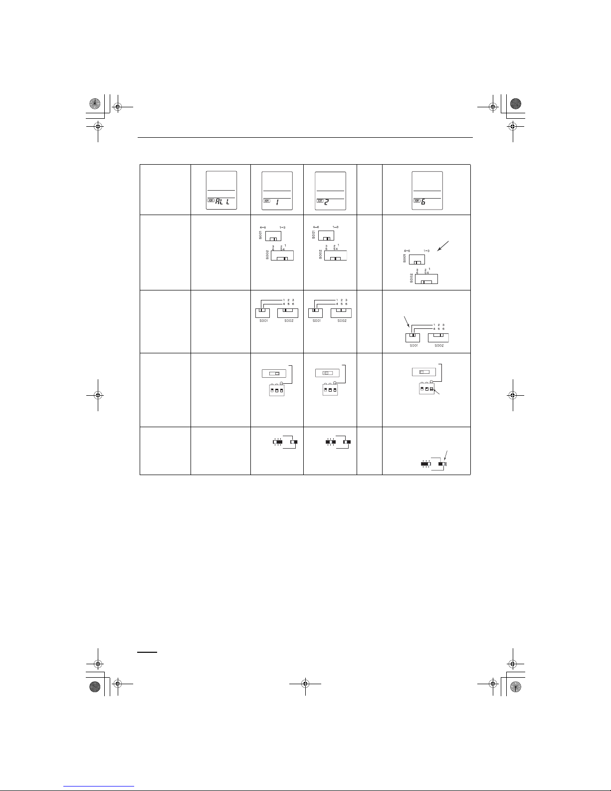
Address Settings (continued)
Wireless remote
control unit
address displays
……
CAFP type
Position of
address switch on
signal receiver
(inside indoor unit)
* The address switch
in the operation
area may be set to
any position.
……
For positions 1, 2 and 3, set the
knob to the left; conversely, for 4, 5
and 6, set the knob to the right.
SPAFP type
Position of
address switch on
signal receiver
(inside indoor unit)
* The address switch
in the operation
area may be set to
any position.
……
For positions 1, 2 and 3, set the
knob to the left; conversely, for 4, 5
and 6, set the knob to the right.
MAFP type
Position of
address switch
inside indoor unit
* The address switch
in the operation
area may be set to
any position.
……
For positions 1, 2 and 3,set the
knob upward (1); conversely, for 4,
5 and 6, set the knob downward
(ON).
DSAFP type
Position of
address switch in
signal receiver
* The address switch
in the operation
area may be set to
any position.
……
For positions 1, 2 and 3, set the
knob to the left; conversely, for 4, 5
and 6, set the knob to the right.
3 2 1 OFF
6 5 4 ON
1 2 3
ON
3 2 1 OFF
6 5 4 ON
1 2 3
ON
3 2 1 OFF
6 5 4 ON
1 2 3
ON
123
456
ADR
123
456
ADR
123
456
ADR
OI-722-14-EG
01_Technibel-PACi_EN.fm Page 14 Thursday, December 9, 2004 11:36 AM
Page 15

15
Emergency Operation
In any of the following events, use the Emergency operation button to operate
the air conditioner on a makeshift basis.
• When there is no charge remaining in the wireless remote control unit’s
batteries
• When the wireless remote control unit has failed
• When the wireless remote control unit has been lost or misplaced
CAFP type Initiate operation using the Emergency operation button in the operation area
of the indoor unit.
SPAFP type Initiate operation using the Emergency operation button in the signal receiver
on the indoor unit.
Operation
Press the Emergency operation button.
The air conditioner initiates a cooling operation when its operation is
started up at a room temperature of 24°C or above.
Conversely, it initiates a heating operation when its operation is started up
at a room temperature below 24°C.
Shutdown
Press the Emergency operation button once more.
OI-722-15-EG
01_Technibel-PACi_EN.fm Page 15 Thursday, December 9, 2004 11:36 AM
Page 16
16
Emergency Operation (continued)
MAFP type Initiate operation using the Emergency operation button in the operation area
of the indoor unit.
• TEST is used to initiate a trial run when the air conditioner is first installed.
It is not used under normal circumstances.
• To restart the wireless remote control unit’s operation, the ON/OFF
operation switch must be set to ON without fail. If it is kept at the OFF
setting, the signals from the wireless remote control unit will not be
accepted.
DSAFP type Initiate operation using the Emergency operation button in the signal receiver.
Operation
Set the ON/OFF operation switch to “OFF” first.
Then set it to “ON.”
If a heat pump is used, the air conditioner initiates a cooling operation
when its operation is started up at a room temperature of 24°C or above
or it initiates a heating operation when its operation is started up at a room
temperature below 24°C.
ON
OFF
TEST
Shutdown
Set the ON/OFF operation switch to “OFF.”
NOTE
1. Press the Emergency operation button.
The air conditioner initiates a cooling operation when its operation is
started up at a room temperature of 24°C or above.
Conversely, it initiates a heating operation when its operation is started
up at a room temperature below 24°C.
2. When the SWING button is pressed, the air direction is automatically
switched from upward to downward or vice versa.
Shutdown
Press the Emergency operation button once more.
OI-722-16-EG
01_Technibel-PACi_EN.fm Page 16 Thursday, December 9, 2004 11:36 AM
Page 17

17
Troubleshooting
Check out the following points before requesting service.
If the trouble persists even after performing the checks recommended above, shut down the air conditioner’s
operation, set the local power switch to OFF, and contact your dealer with the model number and trouble symptoms.
You must NOT attempt to make repairs yourself due to the dangers involved. If one or more of the indication lamps is
blinking, give this information to the dealer as well.
Trouble Possible Cause Remedy
Check again.
The air conditioner
does not run even
when the ON/OFF
operation switch
has been set to
ON.
Is the air conditioner in the shutdown mode or
was the switch operated after a power failure?
Press the wireless remote control unit’s
ON/OFF operation button again.
How about the local power switch? If it was off, set it now to on.
Have any of the fuses blown? If a fuse has blown, contact your dealer.
Is the ON timer operation mode established? Clear the timer operation.
If the signal receiver’s NORMAL/ALL OFF
switch set to “ALL OFF”?
If it is, set it to the “NORMAL” position
and cancel the operation.
Have the wireless remote control unit’s
batteries run down?
If they have, replace them with new
ones.
Do the indication lamps show a cooling/heating
mismatch or is the auto cooling/heating
function not available?
Change the operation mode.
Auto cooling/heating or heating appears on the display even though the air
conditioner is a cooling-only model.
Change the setting of the wireless
remote control unit’s slide switch. (See
page 11)
Trouble Possible Cause
Contact your dealer.
(An indicator lamp is blinking.) • Some kind of trouble has occurred in communication between the
signal receiver and indoor unit. Alternatively, the wrong address has
been set when a wired remote control unit is used.
• Some kind of trouble has occurred in communication between the
indoor unit and outdoor unit.
• The indoor unit’s protection device has been activated. Alter natively, the
auto flap connector of the ceiling panel has been disconnected.
• The outdoor unit’s protection device has been activated.
• Something is wrong with the temperature sensor.
• The outdoor unit’s compressor has been protected.
• A trial run is underway. Set the trial run switch to OFF.
Operation
Timer
Preparing for
operation
Operation
Timer
Preparing for
operation
Operation
Timer
Preparing for
operation
Operation
Timer
Preparing for
operation
Operation
Timer
Preparing for
operation
Operation
Timer
Preparing for
operation
Operation
Timer
Preparing for
operation
OI-722-17-EG
01_Technibel-PACi_EN.fm Page 17 Thursday, December 9, 2004 11:36 AM
Page 18

18
Wired Remote Control Unit
(Optional parts)
Parts Name and Functions
• This remote control unit can be used to operate up to eight indoor units.
Once the operation settings are made, the units can be operated by
simply pressing the ON/OFF operation button.
• In the DSAFP series, the flap position is not shown on the display.
A: ON/OFF operation button This button is for turning the air conditioner on and off.
B: Operation lamp This lamp lights when the air conditioner is turned on.
This lamp blinks when an error occurs or a protective device is activated.
C: MODE button Use this button to select one of the following five operating modes.
(AUTO) : Used to automatically set cooling or heating operation. Only for single
heat pump type
(temperature range: 17 to 27°C)
(HEAT) : Used for normal heating operation. Only for heat pump type
(temperature range: 16 to 30°C)
(DRY) : Used for dehumidifying without changing the room temperature.
(temperature range: 18 to 30°C)
(COOL) : Used for normal cooling operation.
(temperature range: 18 to 30°C)
(FAN) : Used to run the fan only, without heating or cooling operation.
D: Temperature setting
buttons
: Press this button to increase the temperature setting.
: Press this button to decrease the temperature setting.
E: FAN SPEED selector button
(AUTO)
(HI.)
(MED.)
(LO.)
: The air conditioner automatically decides the fan speeds.
: High fan speed
: Medium fan speed
: Low fan speed
I: FLAP button
H: UNIT button
L: SET button
B: Operation lamp
D: Temperature setting
buttons
C: MODE button
N: VENTILATION button
J: TIMER SET button
O: Remote control sensor
F: FILTER button
K: Time setting buttons
G: CHECK button
M: CL button
A: ON/OFF operation button
E: FAN SPEED selector
button
OI-722-18-EG
01_Technibel-PACi_EN.fm Page 18 Thursday, December 9, 2004 11:36 AM
Page 19

19
Parts Name and Functions (continued)
F: FILTER button This button is used to turn off the filter sign ( ). When the filter sign appears
on the display, clean the filter, and then press this button to turn off the sign.
G: CHECK button This button is used only when servicing the air conditioner.
Do not use the CHECK button for normal operation.
H: UNIT button When more than one indoor unit is connected, this button is used to select a
unit when adjusting the airflow direction.
If no unit is selected, the airflow direction of all units can be adjusted
concurrently using the FLAP button.
I: FLAP button 1. Use this button to set the airflow direction to a specific angle.
The airflow direction is displayed on the remote control unit.
Operation mode
Number of airflow direction settings
(COOL) or (DRY) 3
(HEAT) or (FAN) 5
(AUTO)
Cooling mode: 3
Heating mode: 5
• In the cool mode and dry mode, if the flaps are set in a downward
position, condensation may form and drip around the vent.
• Do not move the flap with your hands.
This function is available for models CAFP, SPAFP and MAFP.
(SWEEP) 2. Use this button to make the airflow direction sweep up and down
automatically.
Press this button several times until the symbol appears on the
display.
To stop the swing operation
Press the FLAP button again during the flap swing operation to stop the flap
at the desired position. Then, the airflow can be set from the top position by
pressing the FLAP button again.
Indicator when swing operation is stopped
During cooling and drying, the flap does not stop at the downward position.
Even if the flap is stopped at the downward position during the swing
operation, it does not stop until it moves to the third position from the top.
This function is available for models CAFP, SPAFP and MAFP.
CAUTION
CAUTION
NOTE
Fan and heating Cooling and drying
NOTE
OI-722-19-EG
01_Technibel-PACi_EN.fm Page 19 Thursday, December 9, 2004 11:36 AM
Page 20
20
Parts Name and Functions (continued)
J: TIMER SET button
(OFF Timer)
(OFF Cycle Timer)
(ON Timer)
Use this button while the unit is operating to switch between timer settings.
: The air conditioner stops after a preset time elapses.
:The air conditioner always stops after a preset time elapses.
: The air conditioner starts after a preset time elapses.
K: Time setting buttons : Press this button to increase the time.
: Press this button to decrease the time.
L: SET button Use this button to set the timer.
M: CL button Use this button to clear the timer setting.
N: VENTILATION button This is used when a ventilation fan (available commercially) is connected.
Pressing the VENTILATION button turns the fan on and off. The ventilation
fan also turns on and off when the air conditioner unit is turned on and off.
(The display of the remote control unit shows “ ” while the ventilation fan
is running.)
* If “ ” is shown on the display of the remote control unit when the
VENTILATION button is pressed, this indicates that the ventilation fan is
not connected.
O: Remote control sensor Normally, the temperature sensor of the indoor unit is used to detect the
temperature. However, it is also possible to detect the temperature around
the remote control unit.
For details, contact the dealer where you made the purchase.
(Do not set when using group control.)
1) When two remote control units are being used in one group control*
system,
a) the most recent button that is pressed on any remote control unit is
effective.
b) either a main-remote control unit or a sub-remote control can set the
timer.
* Group control means that maximum up to 8 indoor units can be
concurrently controlled with a remote control unit.
2) If a power failure occurs in timer mode, the time counted up to that point
will be stored in memory.
After power is restored, the timer starts again counting up to the set time.
NOTE
OI-722-20-EG
01_Technibel-PACi_EN.fm Page 20 Thursday, December 9, 2004 11:36 AM
Page 21

21
Display
Description
A: When the unit is in the heating standby mode, the indicator appears.
While this indicator is displayed, the indoor fan turns off or on at low fan
speed.
B: The currently selected operation mode is displayed.
C: This is displayed if a different operation mode was selected already by
another remote control unit and indicates that the mode cannot be
changed.
D: After turning on the mains power switch for the first time, indicator
blinks on the display of the remote control unit. While this is displayed, the
system is automatically checking units, and so wait until the
indicator turns off to operate the remote control unit. When the TIMER
SET button is pressed to set the timer, the indicator flashes.
E: The currently selected FAN SPEED, fan angle and SWEEP status are
displayed.
F: This is displayed only if an abnormality occurs within a unit.
G: When the CHECK button is pressed for more than 4 seconds, the TEST
indicator appears. Then, press the ON/OFF operation button to start test
run.
H: This is displayed to indicate that the system controller is being used for
control. When is flashing on the display, the operation is not accepted
by the system controller.
I: This displays the unit number of the indoor unit selected with the unit
selection button or the indoor/outdoor unit where an error is indicated.
J: This is displayed if it is time to clean the filter.
K: When setting the timer, the selected timer mode is displayed. This displays
the time of the timer. (An alarm message is displayed when an error
occurs.) Pressing the TIMER SET button cycles through the options in this
order: No Display
L: This is displayed when using the remote control unit sensor.
M: This is displayed if a function is unavailable when a button is pressed.
N: This displays the temperature setting.
O: This is displayed when a connected ventilation fan (available
commercially) is operating.
A
BFCH
L
N
MIEGDKJO
Unit No.
1 — 2
Indoor unit No.
Refrigerant circuit No.
OI-722-21-EG
01_Technibel-PACi_EN.fm Page 21 Thursday, December 9, 2004 11:36 AM
Page 22

22
Operation
• To warm up the system, the power mains must be turned on at least five
(5) hours before operation.
STEP 1 To start the air conditioner
Press the operation button (ON/OFF button).
STEP 2 Setting the mode
Press the MODE button to select the mode of your choice.
[ (AUTO), (HEAT), (DRY), (COOL) or (FAN)]
STEP 3 Setting the fan speed
Press the FAN SPEED selector button to select the fan
speed of your choice.
[ (AUTO), (HI.), (MED.) or (LO.)]
If AUTO is selected, the fan speed switches automatically.
STEP 4 Setting the temperature
Use the or button as appropriate to change the
temperature setting as desired.
( reduces the temperature, and increases the
temperature.)
* The temperature cannot be set during FAN mode operation.
STEP 5 Setting the airflow direction
When more than one indoor unit is connected, the UNIT
button is used first to select a unit. Then use the FLAP button
to set the airflow direction to a specific angle or to sweep.
STEP 6 To stop the air conditioner
Press the operation button (ON/OFF button) again.
STEP 2
STEP 1, 6
STEP 3
STEP 4
STEP 5
NOTE
OI-722-22-EG
01_Technibel-PACi_EN.fm Page 22 Thursday, December 9, 2004 11:36 AM
Page 23

23
Operation (continued)
Automatic heating and cooling
(Only for heat pump type)
The air conditioner automatically performs heating and cooling operation
based on the difference between the temperature setting and room
temperature. All indoor units in the same refrigerant system can be operated
with a single group control.
Simultaneous operation of
multiple units (Group control)
Group control is suitable for air conditioning of a large room using multiple air
conditioning units.
• One remote control unit can control up to four indoor units.
• All indoor units have the same settings except for the airflow direction.
• The temperature sensors at the indoor unit side are used.
Outdoor unit
Signal line
Remote control unit
Indoor unit
OI-722-23-EG
01_Technibel-PACi_EN.fm Page 23 Thursday, December 9, 2004 11:36 AM
Page 24

24
Adjusting the Airflow Direction
The functions differ depending on the indoor unit used. The airflow direction
cannot be set using the remote control unit for any unit which is not listed
below.
4-way type (CAFP), ceiling mounted type (SPAFP) and wall mounted type
(MAFP).
• Never use your hands to move the flap (vertical airflow flap) that is
controlled using the remote control unit.
• When the air conditioner is turned off, the flap (vertical airflow flap)
automatically moves to the downward position.
• The flap (vertical airflow flap) moves to the upward position when
performing the standby operation for heating. The swing operation is
made after the standby operation for heating is released, but swing is
indicated on the remote control unit even during the standby operation for
heating.
Setting the airflow direction The airflow direction changes each time the FLAP button is pressed
during operation.
To activate the swing
operation
Press the FLAP button to set the flap (vertical airflow flap) to the downward
position, and then press the FLAP button again. This displays , and the
airflow automatically swings up and down.
To stop the swing operation Press the FLAP button again during the flap swing operation to stop the flap
at the desired position. Then, the airflow can be set from the top position by
pressing the FLAP button again.
Indicator when swing operation is stopped
During cooling or drying operation, the flap will not stop at the downward
position. Even if the flap is stopped at the downward position during the swing
operation, it will not stop until it moves to the third position from the top.
Heating Cooling and drying Fan operation All operations
Set the flap (vertical airflow flap) to the downward
position. If the flap is set to the upward position,
the warm air may not reach the floor.
The flap (vertical airflow flap) can
be set to one of three positions.
Initial setting
Initial setting
Initial setting
Continuous
operation
Fan and heating Cooling and drying
OI-722-24-EG
01_Technibel-PACi_EN.fm Page 24 Thursday, December 9, 2004 11:36 AM
Page 25

25
Adjusting the Airflow Direction (continued)
Semi-concealed type
This air conditioner is equipped with auto flaps.
You can set the airflow direction to a specific angle or to the sweep mode
using the remote control unit.
Do not move the flap with your hands.
• The air outlet flap can be easily removed and washed with water.
• Be sure to always stop operation before removing the flap.
• After washing with water, allow it to dry, and then remount it with the arrow
facing outward.
Ceiling mounted type (SPAFP)
A. Vertical directions (automatic)
This air conditioner is equipped with an auto flap. You can set the airflow
direction to a specific angle or to the sweep mode using the remote control
unit. (Refer to the description of the remote control unit.)
Do not move the flap with your hands.
B. Horizontal directions (manual)
The horizontal airflow direction can be adjusted manually by moving the
vertical vanes to the left or right.
4-way type (CAFP)
CAUTION
Auto flap
Vertical vane
CAUTION
OI-722-25-EG
01_Technibel-PACi_EN.fm Page 25 Thursday, December 9, 2004 11:36 AM
Page 26
26
Adjusting the Airflow Direction (continued)
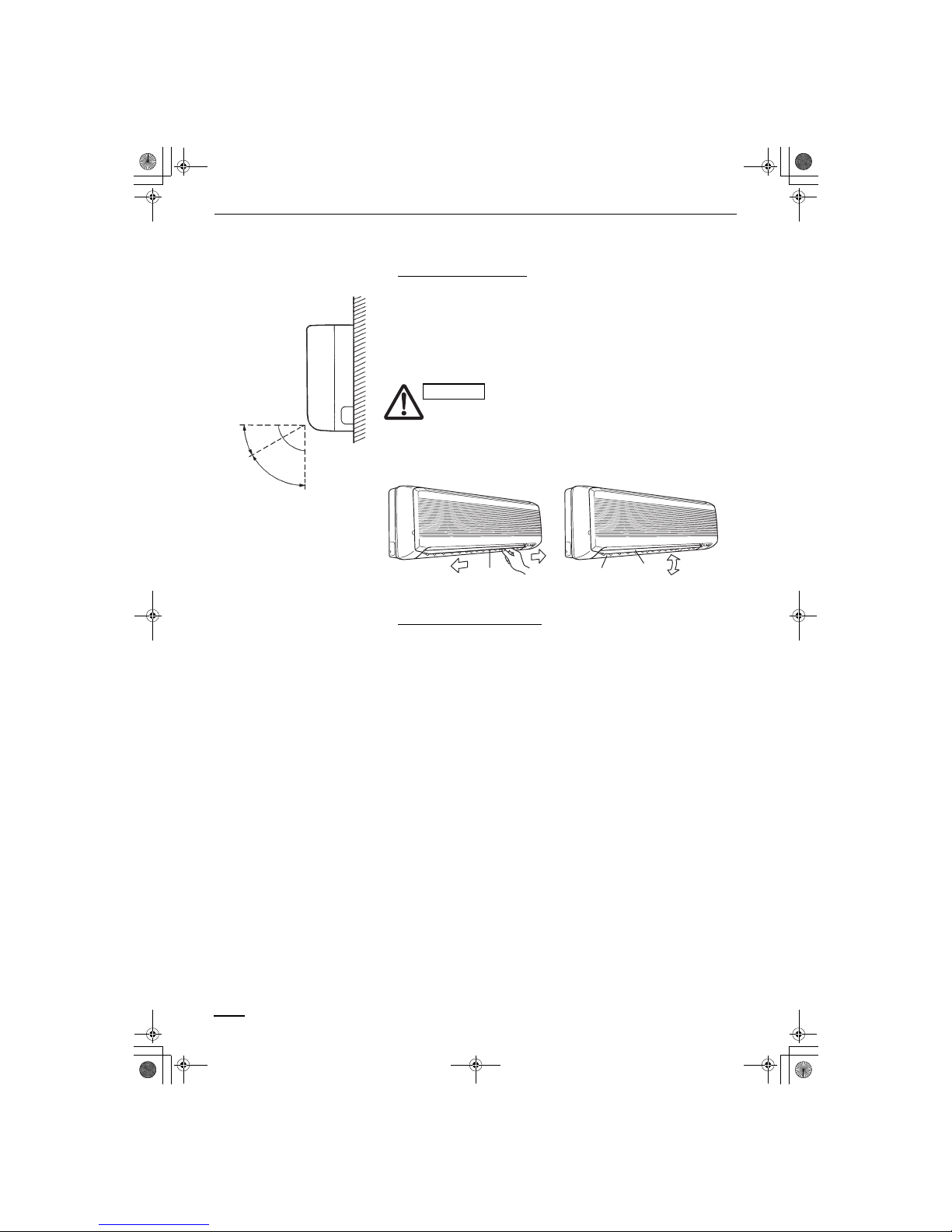
Wall mounted type (MAFP)
A. Vertical directions (automatic)
Confirm that the remote control unit has been turned on. Press the FLAP
button to start the flap moving up and down. If you want to stop the flap
movement and to direct the air in the desired direction, press the FLAP button
again. In the cool mode, don’t direct the flap down more than 30°, otherwise,
condensation may drip on to the floor. Zone ‘‘A’’ is the recommended flap
position for cooling.
Do not move the flap with your hands.
B. Horizontal directions (manual)
The horizontal airflow direction can be adjusted manually by moving the
vertical vanes to the left or right.
Concealed duct type (DSAFP)
This air conditioner is not equipped with air outlet parts. These must be
obtained locally. Please refer to the manual of the locally adopted air outlet
parts.
Zone
‘‘A’’ for
cooling
30°
Indoor unit
Zone ‘‘B’’ for
heating
60°
CAUTION
Left
Vertical
vanes
Right
Air outlet
grille
Flap
Down
Up
OI-722-26-EG
01_Technibel-PACi_EN.fm Page 26 Thursday, December 9, 2004 11:36 AM
Page 27
27
Adjusting the Airflow Direction for
Multiple Indoor Units Using a Single
Remote Control Unit
• The airflow direction cannot be set using the remote control unit for the
concealed duct type (DSAFP).
• If multiple indoor units are connected to a remote control unit, the airflow
direction can be set for each indoor unit by selecting the indoor units (see
the operation below).
Auto Flap ( ) button • To set the airflow for individual units, press the UNIT button. Display shows
the indoor unit number under group control. Set the airflow direction for the
indoor unit that is shown on the display.
• Each time UNIT is pressed, the indicator changes in the order shown
below.
• When nothing is displayed, you can make the setting for all indoor units in
one operation.
• The unit number is displayed as Outdoor Unit Number–Indoor Unit
Number. It varies depending on the number of units under group control.
One outdoor unit and four indoor units
Two outdoor units and four indoor units
No display
Unit No.
1–1
Unit No.
1–2
Unit No.
1–3
Unit No.
1–4
ÎÎÎ
Î
Î
No display
Unit No.
1–1
Unit No.
1–2
Unit No.
1–3
Unit No.
2–4
Î
Unit No.
1–4
Unit No.
2–1
ÎÎÎÎ
Î
OI-722-27-EG
01_Technibel-PACi_EN.fm Page 27 Thursday, December 9, 2004 11:36 AM
Page 28

28
Special Remarks
How it works • Once the room temperature reaches the level that was set, the unit
repeats the cycle of turning on and off automatically.
• In order to prevent the humidity in the room from rising again, the indoor
fan also turns off when the unit stops operating.
• The fan speed is set to ‘‘LO.’’ automatically, and cannot be adjusted.
• ‘‘DRY’’ operation is not possible if the outdoor temperature is 15 °C or less.
Heating performance • Because this appliance heats a room by utilizing the heat of the outside air
(heat pump system), the heating efficiency will fall off when the outdoor
temperature is very low. If sufficient heat cannot be obtained with this heat
pump, use another heating appliance in conjunction with this unit.
Defrosting • When the outdoor temperature is low, frost or ice may form on the outdoor
heat exchanger coil, reducing the heating performance. When this
happens, a microcomputer-controlled defrosting system operates. At the
same time, the fan on the indoor unit stops (or runs at very low speed in
some cases) and the ‘‘STANDBY’’ indicator appears on the display until
defrosting is completed. Heating operation then restarts after several
minutes. (This interval will vary slightly depending upon the outdoor
temperature and the way in which frost forms.)
(standby) on the display • For several minutes after the start of heating operation, the indoor fan will
not start running (or it will run at very low speed in some cases) until the
indoor heat exchanger coil has warmed up sufficiently. This is because a
cold draft prevention system is operating. During this period, the ‘‘ ’’
(standby) indicator remains displayed.
• ‘‘ ’’ (standby) remains displayed during defrosting or when the
compressor has been turned off (or when the unit is running at very low
speed) by the thermostat when the system is in the heating mode.
• Upon completion of defrosting and when the compressor is turned on
again, ‘‘ ’’ (standby) will turn off automatically as heating operation
resumes.
Should the power fail while the unit is running
If the power supply for this unit is temporarily cut off, the unit will automatically
resume operation (once the power is restored) using the same settings before
the power was cut off.
‘‘DRY’’ Operation
Heating Operation
NOTE
OI-722-28-EG
01_Technibel-PACi_EN.fm Page 28 Thursday, December 9, 2004 11:36 AM
Page 29

29
Setting the Timer
Using the timer • Set the timer during air conditioner operation.
Time indicator of timer Each time is pressed, the time setting increases at 0.5-hour (30 minute)
intervals. The upper limit is 72.0 hours.
Each time is pressed, the time setting decreases at 0.5-hour (30 minute)
intervals. The lower limit is 0.5 hours.
Timer indicator The timer cycles through the following options each time (TIMER
SET button) is pressed.
OFF timer Use this mode to turn off the unit automatically after a preset time elapses.
OFF cycle timer Use this mode to always turn off the unit automatically after a preset time
elapses.
ON timer Use this mode to start the unit automatically after a preset time elapses.
When two remote control units are being used, either a main-remote control
unit or a sub-remote control unit can be used for timer operations.
Recommended usage Display
To stop the air conditioner after a preset time
elapses
OFF timer
To always stop the air conditioner after a preset
time elapses
OFF cycle
timer
To start the air conditioner after a preset time
elapses
ON timer
No display
OFF
ON
Set time
OFF
ONON
OFF
Set time
Set time
OFF
ON
Set time
NOTE
OI-722-29-EG
01_Technibel-PACi_EN.fm Page 29 Thursday, December 9, 2004 11:36 AM
Page 30
30
Setting the Timer (continued)
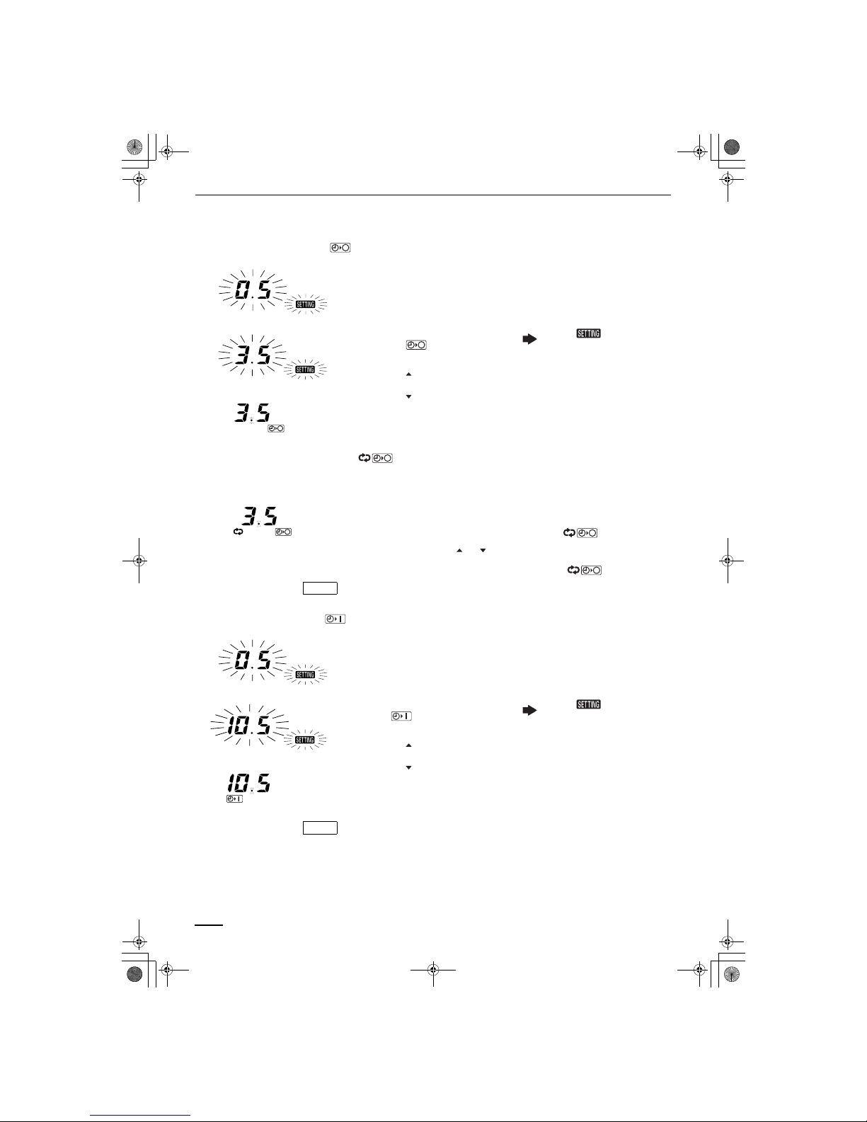
How to set the OFF timer ( )
Example: Stopping the air conditioner after 3.5 hours of operation
Operation Indication
1. Press the ON/OFF button once to
start the air conditioner.
2. Press the TIMER SET button to
select the mode.
The and time
indications (hour) flash.
3.
• Press the button until 3.5 is
displayed.
• Press the button if the set time
is exceeded.
4. Press the SET button to set the
OFF timer.
How to set the OFF cycle timer ( )
Example: Always stopping the air conditioner after 3.5 hours of operation
Operation
1. Press the ON/OFF button to start the air conditioner.
2. Press the TIMER SET button twice to select the mode.
3. Set the time using the or button.
4. Press the SET button to set the OFF cycle timer ( ).
When the OFF cycle timer is set, the unit will always stop after 3.5 hours of
operation.
How to set the ON timer ( )
Example: Starting the air conditioner 10.5 hours after the ON time setting
Operation Indication
1. Press the ON/OFF button to start
the air conditioner.
2. Press the TIMER SET button to
select mode.
The and time
indications (hour) flash.
3.
• Press the button until 10.5 is
displayed.
• Press the button if the set time
is exceeded.
4. Press the SET button to set the ON
timer.
When the ON timer is set, the unit enters the paused state.
Canceling timer operation
Press the CL button to cancel operation. The time setting is canceled, and
the timer indicator no longer appears on the display.
NOTE
NOTE
OI-722-30-EG
01_Technibel-PACi_EN.fm Page 30 Thursday, December 9, 2004 11:36 AM
Page 31

31
Care and Cleaning
1. For safety, be sure to turn the air conditioner off and also to
disconnect the power before cleaning.
2. Do not pour water on the indoor unit to clean it. This will damage the
internal components and cause an electric shock hazard.
Air intake and outlet side
(Indoor unit)
Clean the air intake and outlet side of the indoor unit with a vacuum cleaner
brush, or wipe them with a clean, soft cloth.
If these parts are stained, use a clean cloth moistened with a mild liquid
detergent. When cleaning the air outlet side, be careful not to force the vanes
out of place.
1. Never use solvents or harsh chemicals when cleaning the indoor
unit. Do not wipe plastic parts using very hot water.
2. Some metal edges and the fins are sharp and may cause injury if
handled improperly; be especially careful when you clean these
parts.
3. The internal coil and other components of the outdoor unit must be
cleaned every year. Consult your dealer or service center.
Air filter The air filter collects dust and other particles from the air and should be
cleaned at regular intervals as indicated in the table below or when the filter
indication ( ) on the display of the remote control unit (wired type) shows that
the filter needs cleaning. If the filter gets blocked, the efficiency of the air
conditioner drops greatly.
Type CAFP SPAFP MAFP DSAFP*
Period Six months Two weeks Two weeks (depending on filter specifications)
*Concealed duct type (DSAFP):
An air filter is not provided with this air conditioner at the time of shipment. To
get clean air and to extend the service life of the air conditioner, an air filter
must be installed in the air intake. For installation and cleaning the air filter,
consult your dealer or service center.
The frequency with which the filter should be cleaned depends on the
environment in which the unit is used.
How to clean the filter
1. Remove the air filter from the air intake grille.
2. Use a vacuum cleaner to remove light dust. If there is sticky dust on the
filter, wash the filter in lukewarm, soapy water, rinse it in clean water, and
dry it.
CAUTION
NOTE
OI-722-31-EG
01_Technibel-PACi_EN.fm Page 31 Thursday, December 9, 2004 11:36 AM
Page 32

32
Care and Cleaning (continued)
How to remove the filter
4-way semi-concealed type
(CAFP):
1. Use a screwdriver to remove the bolt screw on each side for the two
latches. (Be sure to reattach the two bolt screws after cleaning.)
2. Press on the two latches of the air intake grille with your thumbs in the
direction of the arrow to open the grille.
3. Open the air intake grille downward.
• When cleaning the air filter, never remove the safety chain. If it is
necessary to remove it for servicing and maintenance inside, be sure
to reinstall the safety chain securely (hook on the grille side) after the
work.
• When the filter has been removed, rotating parts (such as the fan),
electrically charged areas, etc. will be exposed in the unit’s opening.
Bear in mind the dangers that these parts and areas pose, and
proceed with the work carefully.
4. Remove the air filter attached to the air intake grille.
Ceiling-mounted type (SPAFP): 1. Take hold of the finger-hold on the air intake grille and press it to the rear,
and the grille will open downward.
2. Take hold of the finger-hold on the air filter, pull it toward you.
Wall-mounted type (MAFP): 1. Move the flap on the air outlet grille to its lowest position with the remote
control unit.
2. The filter is disengaged by pushing the tab up gently. Hold the air filter by
the tab at the bottom, and pull downward.
When replacing the filter, make sure that the FRONT mark is facing you.
Push it up until you hear it click back into position.
CAUTION
Air intake
grille
Bolt screws
Latch
Safety chain
Air filter
Finger-hold
Air filter
Air filter finger-hold
Air intake grille
Air intake grille
Air filter
OI-722-32-EG
01_Technibel-PACi_EN.fm Page 32 Thursday, December 9, 2004 11:36 AM
Page 33

33
Troubleshooting
If your air conditioner does not work properly, first check the following points before requesting service. If it still does
not work properly, contact your dealer or a service center.
Tips for Energy Saving
Trouble Possible Cause Remedy
Air conditioner does not run at all. 1. Power failure. 1.
After a power outage, press ON/
OFF operation button on the
wired remote control unit.
2. Leakage circuit breaker has
tripped.
2. Contact service center.
3. Line voltage is too low. 3. Consult your electrician or dealer.
4. Operation button is turned off. 4. Press the button again.
5. The wired remote control unit or
heat pump is malfunctioning.
(
The inspection mark and the
letters E, F, H, L, P in
combination with numbers
appear on the LCD of the wired
remote control unit.)
5. Consult your dealer.
Compressor runs but soon stops. 1. Obstruction in front of condenser
coil.
1. Remove obstruction.
Poor cooling (or heating)
performance.
1. Dirty or clogged air filter. 1. Clean air filter to improve the
airflow.
2. Heat source or many people in
room.
2. Eliminate heat source if possible.
3. Doors and/or windows are open. 3. Shut them to keep the heat (or
cold) out.
4. Obstacle near air intake or air
discharge port.
4. Remove it to ensure good airflow.
5. Thermostat is set too high for
cooling (or too low for heating).
5. Set the temperature lower (or
higher).
6. (Defrosting system does not work.) 6. (Consult your dealer.)
Avoid • Do not block the air intake and outlet of the unit. If either is
obstructed, the unit will not work well, and may be damaged.
• Do not let direct sunlight into the room. Use sunshades, blinds or curtains.
If the walls and ceiling of the room are warmed by the sun, it will take
longer to cool the room.
Do • Always try to keep the air filter clean. (Refer to “Care and Cleaning”.) A
clogged filter will impair the performance of the unit.
• To prevent conditioned air from escaping, keep windows, doors and any
other openings closed.
Should the power fail while the unit is running
If the power supply for this unit is temporarily cut off, the unit will automatically
resume operation once power is restored using the same settings before the
power was cut off.
NOTE
OI-722-33-EG
01_Technibel-PACi_EN.fm Page 33 Thursday, December 9, 2004 11:36 AM
Page 34

R.D. 28 Reyrieux BP 131-01601 Trévoux CEDEX France
Tél. 04.74.00.92.92 - Fax 04.74.00.42.00
R.C.S. Bourg-en-Bresse B 759 200 728
 Loading...