

Page 1

08180012-2 03/2003
TECHNICAL DATA & SERVICE MANUAL
MODELS WITH R407C
SMDV
Page 2

PAGE
UNIT SPECIFICATIONS
3
INDOOR UNIT COMPONENTS SPECIFICATION
4-5
OUTDOOR UNIT COMPONENTS SPECIFICATION
6
UNIT DIMENSIONS 6
ROOM TEMPERATURE CONTROL
7
HEAT EXCHANGER FROSTING PREVENTION
7
PERFORMANCE CHART
8
THE UNIT DOES NOT WORK 9
ELECTRICAL CIRCUIT INTERRUPTED AFTER "ON" IS PRESSED
9
ELECTRIC CIRCUIT INTERRUPTED 3 MINUTES
AFTER "ON" IS PRESSED
10
FAN MOTOR DOES NOT WORK WHILE "ON" BUTTON
IS PRESSED.
10
FAN MOTOR WORKS AT ONE SPEED ONLY (FMI) 11
POOR COOLING 11
FAN MOTOR WORKS NORMALLY BUT THE
COMPRESSOR DOES NOT OPERATE (FMI)
12
OUTDOOR UNIT FAN (FMO) DOES NOT OPERATE
12
THE FLASHING LED IS ON, AND THE UNIT NOT OPERATE
13
COMPRESSOR DOES NOT WORK BUT FAN MOTOR OPERATE NORMALLY
13
ELECTRIC WIRING DIAGRAM
14/15
1;ADDED NEW ELECTRIC WIRING DIAGRAM FOR MODELS SMDV143C5
REVISIONS
CONTENTS
2
Page 3

TECHNICAL DATA
UNIT SPECIFICATIONS
MODEL
SMDV9XC5 SMDV11XC5 SMDV14XC5
PERFORMANCES (NOTE 1)
COOLING
Power source
230V
Capacity
BTU/h
8500
9890
12600
W
2480
2900
3700
Air flow rate (evaporator)
High/low
m³/h
420/320
420/320
460/370
Air flow rate (condenser)
High/low
m³/h
1200
1200
1350
Moisture removal l/h 0,8 1 1,6
ELECTRICAL RATINGS
Voltage rating
230V ~ 50Hz
Available voltage range
V
198÷264
Running amperes
A
4,1
4,6
6,1
Power input
W
930
1030
1300
Coefficient of performance
W/W
2,833
Compressor locked rotor amperes A 20 23 35
FEATURES
Controls/Temperature controls
Control unit
Fan speed
Compressor
Refrigerant/standard charge at shipment
R407C g
750
870
1040
Refrigerant control
Noise level Lp (NOTE 3) INT.high/low dB(A) 44/40 44/40 47/45
EXTERNAL
dB(A)
484841
Flexible tube lenght
m
2,5 m
DIMENSIONS & WEIGHT
Internal unit
Height
mm
800
Width mm 470
Depth mm 310
External unit
Height
mm
435
435
490
Width
mm
440
440
525
Depth
mm
230
230
250
Net weight
Internal unit
Kg3940
41
External unit Kg 8,5 9,5 13
Data can be changed without notice
NOTE 1: Rating conditions (ISO 5151):
Internal temperature: 27°C D.B. , 19°C W.B.
External temperature: 32°C D.B. , 24°C W.B.
NOTE 2: Operating limits: MINIMUM MAXIMUM
Internal temperature: 15°C D.B.,12°C W.B. 32°C D.B.,23°C W.B.
External temperature: 15°C D.B. 46°C D.B.
NOTE 3: Refering data :
Internal unit: room size 100m3 ; reverberation time 0,5sec.; distance 2m.
External unit: hemispheric radiance; distance 4m.
switches on the unit
two
Rotary (hermetic)
Capillary tube
Electronic/ I.C. thermostat
3
Page 4

TECHNICAL DATA
INDOOR UNIT COMPONENTS SPECIFICATION
MODEL
SMDV9XC5 SMDV11XC5 SMDV14XC5
CONTROLLER P.C.B.
(CE)
RY1 SPLIT / RY1.1 SPLIT
Controls
Thermostat
Setting
°C
15 ± 1,5°C ÷ 31 ± 2°C
Differential
°C
0,9 ± 0,2°C
Starting delay time
3min. ± 10sec.
Function selection and indicator lamps
Frosting prevention
OPEN
°C
1 ± 1°C
CLOSE
°C
6 ± 1°C
Transformer
Power
1,5VA
Primary 220V
Secondaty 10,5V
Primary resistance
20°C
2754
Ω
±10%
Secondary resistance
20°C
17,1
Ω
±10%
COIL TEMPERATURE SENSOR
(TH1)
NTC
Resistance
kΩ
-20°C 5846±5% ; 20°C 604±5%
-10°C 3159±5% ; 30°C 368±5%
0°C 1766±5% ; 40°C 230±5%
10°C 1018±5% ; 50°C 147±5%
AIR TEMPERATURE SENSOR
(TH2)
NTC
Resistance
k
Ω
10°C 1018±5% ; 30°C 368±5%
15°C 781±5% ; 35°C 290±5%
20°C 604±5% ; 40°C 230±5%
25°C 470±5% ; 50°C 147±5%
FAN & FAN MOTOR (FMI) M01582
Cross - Flow
Dimensions
mm
Ø 125 x 295
Power supply
230V~50Hz
N° of poles
4
High/low speed
rpm
1150/870
1180/950
1260/1040
Nominal input (230V) W 36
Coil resistance (20°C)
Ω
GRY-WHT : 392 ± 5%
WHT-YEL : 213 ± 5%
YEL-PNK : 66 ± 5%
GRY-BRN : 163 ± 5%
Safety device
Internal thermostat
Setting:
open
150±10
close
Automatic
RUN CAPACITOR
(C1)
INDOOR FAN MOTOR
Capacity
µF
0,6
0,61Tension
V~
440
440
440
CONDENSER PUMP
(PC)
PC 95643
Power supply
230V~50Hz
Nominal input (230V)
W
12±10%
Coil resistance (20°C)
Ω
122±10%
PUMP RELAY
(RP)--
FINDER 60.62
Coil power
--230V~50Hz
Coil resistance (20°C)
k
Ω
--7,250±10%
Contact rating
--10A - 250V
FLOAT MICROSWITCH
CROUZET F83161.3
Contact rating
10(4)A - 250VAC
Float
up
Open
Down
Close
Electronic microprocessor
COOLING / FAN
HIGH/LOW speed
ALARM lamp
ON / OFF
4
Page 5

TECHNICAL DATA
MODELS
POWER RELAY (COMPRESSOR)
FINDER OMRON FINDER OMRON OMRON OMRON
65.31 G4F 65.31 G4F G7L G4F
P.C.B.
Type
RY1 RY1.1 RY1 RY1.1 RY1 RY1.1
Coil tension
230V~50Hz 12Vdc 230V~50Hz 12Vdc 230V~50Hz 12Vdc
Coil resistance (20°C)
Ω
7.250±10% 158±10% 7.250±10% 158±10% 21.000±15% 158±10%
Contact rating
30A-250V 20A-250V 30A-250V 20A-250V 25A-250V 20A-250V
COMPRESSOR
(CM)
Model
Nominal input (230V)
W
Compressor oil
cc
Coil resistance (20°C)
C-RΩC-S
Ω
SAFETY DEVICE (OLR)
Operanting temperature Open
Close
Operanting amperes
Open
(Room temperature 25°C)
Operanting temperature
(OLR 1)
Open
Close
Operanting temperature
(OLR 2)
Open
Close
Operanting temperature Open
(Room temperature 25°C)
RUN CAPACITOR (C3)
Capacity µF
Power supply
V~
RUN CAPACITOR
(C4)
COMPRESSOR
Capacity
µF
Power supply
V~
POWER RELAY (RA) COMPRESSOR
Type
Coil tension
V~
Coil resistance (20°C)
k
Ω
Contacts rating
Operating voltage
Operating voltage
CURRENT LIMITER
(LC)
Type
Coil resistance (20°C)
Ω
Induttance ( a 19A~50Hz)
mH
HEAT EXCHANGER
Coils
Rows
Fin pitch mm
Face area m²
SMDV11XC5
500
3,01±7%
550
1,92÷1,84±7%
5,28÷7,1±7%
MRA990003-9201 MST20ALU-9201
3,31±7%
7,82±7%7,35±7%
500
in 6÷16 sec.
135±5°C
69±11°C
19A
in 6÷16 sec.
140±5°C
22,5A
in 6÷16 sec.
CS-7C115
115±4°C
95±10°C
MST56ALU
80235245B
1290
COMPRESSOR
150±5°C
69±11°C
830 950
80225245B 80228245B
22,5
450
20
450
2 3 3
60÷120V~
R143C
690±5%
14
Alluminium fin / Copper tube
EVAPORATOR COIL
1,8
0,118
300V~50Hz
330
AMVL300C
25
450
69±11°C
16A
SMDV9XC5
SMDV14XC5
IF EQUIPED
IF EQUIPED
IF EQUIPED
13,150±2%
20A
185÷217V~
56
5
Page 6

TECHNICAL DATA
OUTDOOR UNIT COMPONENTS SPECIFICATION
MODELS
SMDV9XC5 SMDV11XC5 SMDV14XC5
FAN & FAN MOTOR
(FMO)
M01515
M01515
M01525
proppeler fan
Dimensions
mm
Ø 280
Ø 280
Ø 340
Power supply
n° of poles
446
Rpm
1230
1230
870
Nominal input (230V) W 61 61 75
Coil resistance (20°C)
Ω
BLU - BRN
BLU - BRN
BLU - BRN
263±7%
263±7%
230±7%
Ω
BLU - BLK
BLU - BLK
BLU - BLK
285±7%
285±7%
243±7%
safety device
Setting:
OPEN
°C
150±10
CLOSE
FAN ALTERNATIVE MOTOR (FMO) 40101243-L 40101243-L -
Nominal input (230V)
W7070-Coil resistance (20°C)
Ω
BLU - BRN
BLU - BRN
-
203±7%
203±7%
-
Ω
BLU - BLK BLU - BLK -
201±7%
201±7%
-
safety device Thermostat Thermostat -
Setting: OPEN °C 150±10 150±10 -
CLOSE
Automatic
Automatic
-
RUN CAPACITOR
(C2)
Capacity µF 2 2 2,5
Power supply
V~
450
450
450
HEAT EXCHANGER
Coils
Rows
122
Fin pitch mm
1,4
1,6
1,6
Face area m²
0,23
0,23
0,3
UNIT DIMENSIONS (mm)
AAGFCDB
SMDV97C5
SMDV117C5
SMDV147C5
A
800B470C310D440
440
525F435
435
490G230
230
250
Alluminium / Copper tube
EXTERNAL FAN MOTOR
Automatic
Internal thermostat
230V~50Hz
CONDENSER COIL
6
Page 7

TECHNICAL DATA
ROOM TEMPERATURE CONTROL
Room temperature control is obtained by cycling the compressor ON and OFF by means of room
temperature sensor TH
minimum
2 minutes
ON/OFF SWITCH
COMPRESSOR
SWITCH
COMPRESSOR
SET
TEMPERATURE +1°C
SET
TEMPERATURE
FAN
SET SPEED
NOTES:
1. If the compressor is turned off, the control circuit sets an automatic minimum 3 minutes delay to protect the
compressor from stalling out when trying to start against the high side refrigerant pressure.
2. If the room temperature is 1°C above the set temperature, the compressor starts working if this has been
OFF for at least 3 minutes.
3. If the room temperature is the same or under the set temperature the compressor stops working.
HEAT EXCHANGER FROSTING PREVENTION
The electronic control stops automatically the compressor each time the coil sensor TH reaches a
temperature of 1°C for 8 ÷ 10 minutes long, the compressor starts again automatically when the
temperature of heat exchanger reaches 8°C. The fan goes on working at the set speed.
minimum 10 minimum
minutes 3 minutes
ON/OFF SWITCH
COMPRESSOR
SWITCH
COMPRESSOR
HEAT EXCHANGER
TEMP.= 8 °C
HEAT EXCHANGER
TEMP.= 1 °C
FAN
SET SPEED
7
Page 8
TECHNICAL DATA
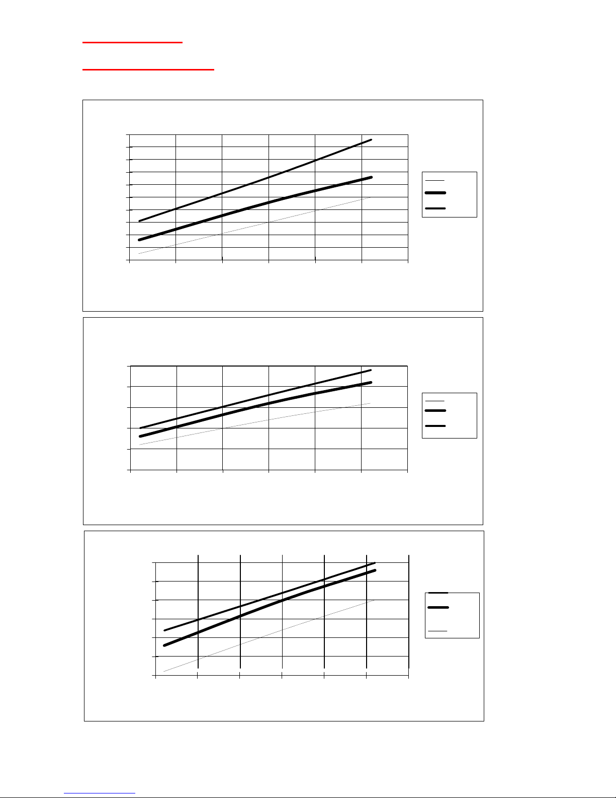
PERFORMANCE CHART
OPERATING CHARACTERISTICS WITH RELATIVE HUMIDITY AROUND 50%
SMDV117C5
3
3,5
4
4,5
5
5,5
20 25 30 35 40 45 50
EXTERNAL TEMPERATURE (°C)
OPERATING CURRENT (A)
21 °C
27 °C
32 °C
SMDV97C5
3
3,2
3,4
3,6
3,8
4
4,2
4,4
4,6
4,8
5
20 25 30 35 40 45 50
EXTERNAL TEMPERATURE (°C)
OPERANTING CURRENT (A)
21 °C
27 °C
32 °C
SMDV147C5
4
4,5
5
5,5
6
6,5
7
20 25 30 35 40 45 50
EXTERNAL TEMPERATURE (°C)
OPERATING CURRENT
(A)
32 °C
27 °C
21 °C
8
Page 9

SERVICE MANUAL
THE UNIT DOES NOT WORK
Check the voltage. Are NO Check the unit YES Check the electrical
there 198 ÷ 264 volts ? electrical cable supply line
YES
(IF INSTALLED) If it is impossible to
Check if programmer NO close the contact,
contact is closed (black - replace the
brown cables). programmer.
YES
Check if the supplied NO Check if tank micro voltage on switch contacts are
the electric control (CE) closed.
(1 - 2 MS contacts)
YES
NO
Replace the electronic Check if the pilot NO Is the flickering alarm
control (CE) lamp is burnt. lamp on the control
Eventually replace panel not visible ?
it.
ELECTRIC CIRCUIT INTERRUPTED WHEN "ON" BUTTON IS PRESSED
Check the unit hardness NO Insulate the short
Is it insulated ? circuit cable
YES
Check if the fan motor is NO Replace the fan motor
working (FMI) (FMI)
YES
Check if the fan motor is NO Replace the fan motor
working (FMO) (FMO)
YES
Check the electronic NO Replace the electronic
control (CE) control (CE)
YES
Check the leds printed NO Replace the leds
circuit. printed circuit.
NO
(IF INSTALLED) Replace the
Check the motor YES
programmer (P). Is it
programmer (P)
short circuited?
9
Page 10

SERVICE MANUAL
ELECTRICAL CIRCUIT INTERRUPTED 3 MINUTES AFTER "ON" BUTTON IS
PRESSED.
COOLING
OPERATION
Check if compressor relay NO
Rebuild the
connections are connections.
insulated.
YES
Check if compressor relay YES
Replace the
works. Is it in short
compressor relay
circuit ? (PR)
NO
Check if compressor
winding are short
circuited.
YES
Replace the
NO
(FMO) Check if
compressor(CM) outdoor fan motor
works
FAN MOTOR (FMI)DOES NOT WORK WHILE "ON" BUTTON IS PRESSED
Disconnect the unit from line. Check if the fan motor is well
fitted and if the blades can rotate
YES NO NO
Check hardness and Fit the fan motor Remove obstruction
various continuities properly or replace or replace fan motor
YES it assembly
Check the capacitor NO
Replace the capacitor
capacity (C)
YES
Check the fan motor INTERRUPTED Replace the fan motor
windings (FMI). assembly
YES
Replace the electronic
control (CE)
10
Page 11

SERVICE MANUAL
FAN WORKS AT ONE SPEED ONLY(FMI)
Check electrical conec- NO Fit electrical connec tions. Is there continuity ? tions properly
YES
Check power supply NO Replace the electronic
on electronic control (CE)
control contacts (CE)
YES
Check fan motor winding
values (FMI))
YES
Replace fan motor (FMI)
POOR COOLING
Is the unit cooling capacity NO Suggest a more power suitable for the room ful unit
thermal loads ?
YES
Are both air filters and heat NO Clean filters and / or
exchanger cleaned ? heat exchanger
YES
Check if difference bet- YES
The unit works properly
ween room air
temperature and outlet air
delivered is up to 10 °C
NO
Low
NO
gas charge
Proceed with
normal operations
foreseen for the
above points
11
Page 12

SERVICE MANUAL
FAN MOTOR WORKS NORMALLY BUT THE COMPRESSOR DOES NOT OPERATE(FMI)
Check hardness
and continuity. Is the
relay compressor
coil (PR white cable)
power supplied ? YES
Replace the relay NO Check if relay YES Is the thermostat NO Adjust thermostat
(PR) contects are closed in the right posi - position
tion ?
YES YES
Replace klixon (ORL)
YES Check compressor Is room tempera - NO The unit cannot
klixon contacts(ORL) ture over 15 °C ? operate below
Are they open ?
15 °C
NO YES
Replace the NO Check the capaci - Check the sensor NO Replace the
capacitor (C) tor capacity (C) continuity (TH) sensor (TH)
on electronic
control (CE)
YES terminal blocks
YES
Replace the NO Check the com - Check electronic
compressor pressor winding control (CE)
continuity
OUTDOOR FAN(FMO) DOES NOT OPERATE.
Have 3 minutes time delay Wait for about 3 minutes
already elapsed since "on"
NO
operation?
YES
Disconnect the unit from line Remove causes stopping
and manually rotate the
NO
rotation.
propeller
YES
Check electrical connections Replace outdoor fan motor
and winding continuity on
NO
(FMO)
outdoor fan(FMO).
YES
Is the voltage in coil relay (RC)
YES
Is the relay contact closed
NO
Replace relay(RC)
(RC) ?
NO
YES
Check electronic control (CE)
Check capacitor capacity.
NO
Replace capacitor
(FMO)
NO
Replace electronic control (CE)
12
Page 13

SERVICE MANUAL
THE FLASHING LED IS ON, AND THE UNIT DOES NOT OPERATE
Check electrical connections
and cable continuity.
YES
Check safety micro floating (MS)
NO
Replace safety micro floating (MS)
YES
Check condensate pump motor
NO
Replace condensate pump motor
(PC)
(PC)
YES
Check pump relay (RP)
NO
Replace pump relay (RP)
YES
Replace safety relay (RS)
COMPRESSOR DOES NOT WORK BUT FAN MOTOR OPERATES NORMALLY.
Check hardness and continuities. Have 3 minutes time delay Wait for about 3 minutes
Is relay compressor coil power NO already elapsed since"on" NO
supplied (RC) ?
operation ?.
YES YES
Replace
NO
Check if relay
Is the thermostat properly
NO
Properly adjust
relay(RC) contact is closed set? thermostat position.
YES
YES
Replace
NO
Check if
Is it properly fitted? It could
NO
Fit it properly,
klixon(K)
compressor
be fitted inversely.
klixon is open
YES
YES
Replace
NO
Check
Is the rom temperature over
NO
Below 15 °C the unit
compressor.
compressor
15 °C
cannot work.
capacitor
capacitor(C)
YES
YES
Replace
NO
Check
Check sensor continuity of
NO
Replace sensor (TH)
compressor.
compressor
(TH) CE terminal blocks.
winding continuity
YES
Check electronic control.(CE)
13
Page 14
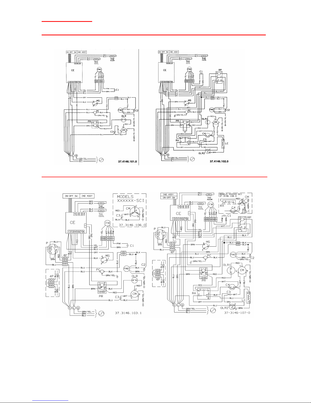
TECHNICAL DATA
ELECTRICAL WIRING DIAGRAM FOR MODELS WITH POWER RELAY 220V AND PCB RY1
SMDV147C5
ELECTRICAL WIRING DIAGRAM FOR MODELS WITH POWER RELAY 12V AND PCB RY1.1
SMDV147C5
Legend of colors
C/CM
COMPRESSOR
S/THx
SENSOR
N/BLK
BLACK
CVx/Cx
CAPACITOR
F/TF
THERMOFUSE
B/BLU
BLUE
RE
ELECTRIC HEATER
TS
SAFETY THERMOSTAT
M/BRN
BROWN
MVx/FMx
FAN MOTOR
P
PROGRAMMER
G/V-GRN/YEL
GREEN/YELLOW
K/ORL
OVERLOAD PROTECTOR
RP
PUMP RELAY
A/ORG
ORANGE
CE
ELECTRONIC CONTROL
IM
MOTOR IMPEDANCE
R/RED
RED
PR
COMPRESSOR RELAY
RS
SAFETY RELAY PUMP
W/WHT
WHITE
MP
PUMP FLOAT MICROSWITCH
PC
PUMP
YEL
YELLOW
MS
SAFETY FLOAT MICROSWITCH
GRN
GREEN
RR
ELECTRIC HEATER RELAY
PNK
PINK
G/GRY
GREY
SMDV97C5-SMDV117C5
SMDV9XC5-SMDV11XC5
14
Page 15

TECHNICAL DATA
ELECTRICAL WIRING DIAGRAM FOR MODELS WITH POWER RELAY 12V AND PCB RY1.1
Legend of colors
C/CM
COMPRESSOR
S/THx
SENSOR
N/BLK
BLACK
CVx/Cx
CAPACITOR
F/TF
THERMOFUSE
B/BLU
BLUE
RE
ELECTRIC HEATER
TS
SAFETY THERMOSTAT
M/BRN
BROWN
MVx/FMx
FAN MOTOR
P
PROGRAMMER
G/V-GRN/YEL
GREEN/YELLOW
K/ORL
OVERLOAD PROTECTOR
RP
PUMP RELAY
A/ORG
ORANGE
CE
ELECTRONIC CONTROL
IM
MOTOR IMPEDANCE
R/RED
RED
PR
COMPRESSOR RELAY
RS
SAFETY RELAY PUMP
W/WHT
WHITE
MP
PUMP FLOAT MICROSWITCH
PC
PUMP
YEL
YELLOW
MS
SAFETY FLOAT MICROSWITCH
GRN
GREEN
RR
ELECTRIC HEATER RELAY
PNK
PINK
G/GRY
GREY
SMDV143C5
15
 Loading...