

Technibel KPA128R5TAA, GR79R5TBA, GR99R5TBA, MCAV127R5VAB, MCAV77R5TA Technical & Service Manual
...Page 1
MCAV77R5VAA - GR79R5TBA
MCAV97R5VAA - GR99R5TBA
MCAV127R5VAB - GR129R5TBA
7(&+1,&$/6(59,&(0$18$/
63/,76<67(0$,5&21',7,21(5
KPA128R5TAA - GR129R5TBA
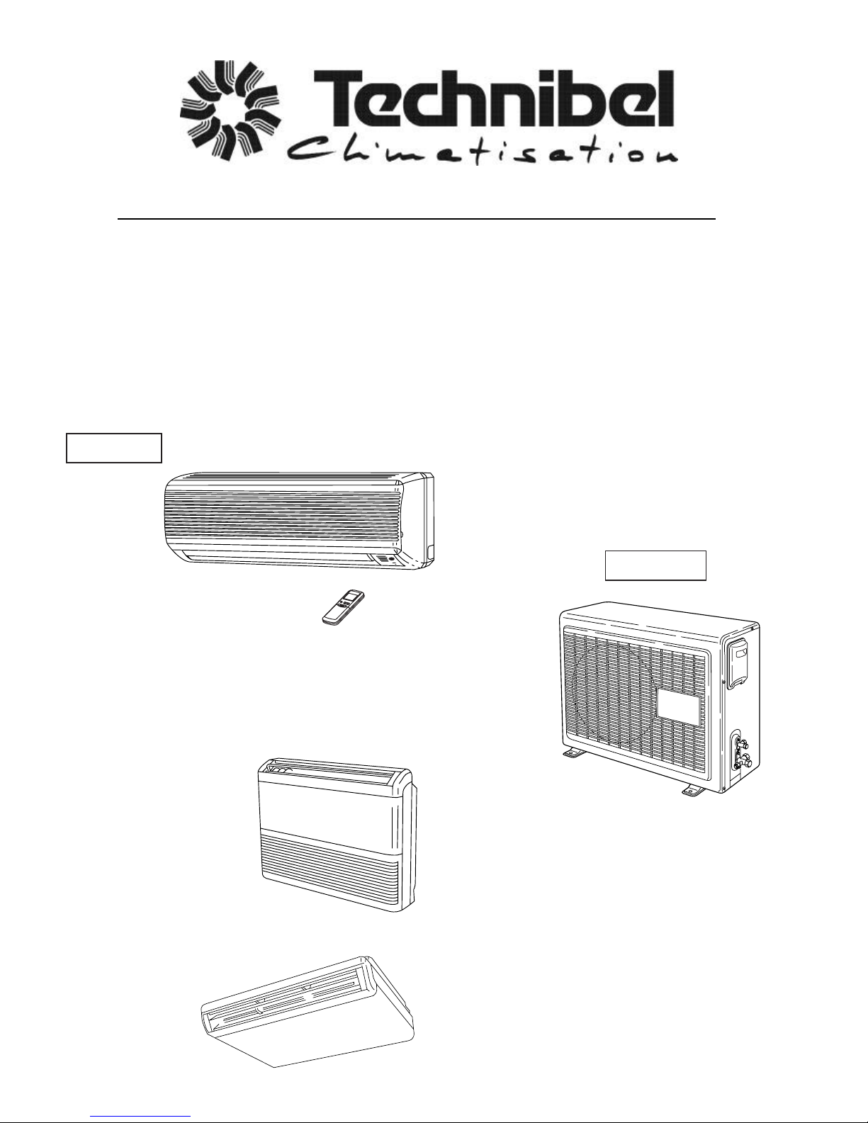
Indoor Unit
Outdoor Unit
MCAV77R5VAA
MCAV97R5VAA
MCAV127R5VAB
GR79R5TBA
GR99R5TBA
GR129R5TBA
Ceiling-Mounted
Floor-Mounted
KPA128R5TAA
0.8180.072.0 04/2001
Page 2

i
Important!
Please Read Before Starting
This air conditioning system meets strict safety and
operating standards. As the installer or service person,
it is an important part of your job to install or service the
system so it operates safely and efficiently.
For safe installation and trouble-free operation, you
must:
●Carefully read this instruction booklet before
beginning.
●Follow each installation or repair step exactly as
shown.
●Observe all local, state, and national electrical codes.
●Pay close attention to all warning and caution notices
given in this manual.
This symbol refers to a hazard or
unsafe practice which can result
in severe personal injury or
death.
This symbol refers to a hazard or
unsafe practice which can result
in personal injury or product or
property damage.
If Necessary, Get Help
These instructions are all you need for most installation
sites and maintenance conditions. If you require help
for a special problem, contact our sales/service outlet
or your certified dealer for additional instructions.
In Case of Improper Installation
The manufacturer shall in no way be responsible for
improper installation or maintenance service, including
failure to follow the instructions in this document.
Special Precautions
When Wiring
ELECTRICAL SHOCK CAN CAUSE
SEVERE PERSONAL INJURY OR
DEATH. ONLY A QUALIFIED,
EXPERIENCED ELECTRICIAN SHOULD
ATTEMPT TO WIRE THIS SYSTEM.
• Do not supply power to the unit until all wiring and
tubing are completed or reconnected and checked.
• Highly dangerous electrical voltages are used in this
system. Carefully refer to the wiring diagram and
these instructions when wiring. Improper connections
and inadequate grounding can cause accidental
injury or death.
• Ground the unit following local electrical codes.
• Connect all wiring tightly. Loose wiring may cause
overheating at connection points and a possible fire
hazard.
WARNING
CAUTION
WARNING
When Transporting
Be careful when picking up and moving the indoor and
outdoor units. Get a partner to help, and bend your
knees when lifting to reduce strain on your back. Sharp
edges or thin aluminum fins on the air conditioner can
cut your fingers.
When Installing…
…In a Ceiling or Wall
Make sure the ceiling/wall is strong enough to hold the
unit’s weight. It may be necessary to construct a strong
wood or metal frame to provide added support.
…In a Room
Properly insulate any tubing run inside a room to
prevent “sweating” that can cause dripping and water
damage to walls and floors.
…In Moist or Uneven Locations
Use a raised concrete pad or concrete blocks to
provide a solid, level foundation for the outdoor unit.
This prevents water damage and abnormal vibration.
…In an Area with High Winds
Securely anchor the outdoor unit down with bolts and a
metal frame. Provide a suitable air baffle.
…In a Snowy Area (for Heat Pump-type Systems)
Install the outdoor unit on a raised platform that is
higher than drifting snow. Provide snow vents.
When Connecting Refrigerant Tubing
• Use the flare method for connecting tubing.
• Apply refrigerant lubricant to the matching surfaces
of the flare and union tubes before connecting them,
then tighten the nut with a torque wrench for a leakfree connection.
• Check carefully for leaks before starting the test run.
When Servicing
• Turn the power off at the main power box (mains)
before opening the unit to check or repair electrical
parts and wiring.
• Keep your fingers and clothing away from any
moving parts.
• Clean up the site after you finish, remembering to
check that no metal scraps or bits of wiring have
been left inside the unit being serviced.
Others
• Ventilate any enclosed areas when installing or
testing the refrigeration system. Escaped refrigerant
gas, on contact with fire or heat, can produce
dangerously toxic gas.
• Confirm upon completing installation that no
refrigerant gas is leaking. If escaped gas comes in
contact with a stove, gas water heater, electric room
heater or other heat source, it can produce
dangerously toxic gas.
CAUTION
Page 3

Table of Contents
Page
1.OPERATING RANGE..............................................................................................................................1
2.SPECIFICATIONS
2-1.Unit Specifications..........................................................................................................................2
2-2.Major Component Specifications....................................................................................................6
2-3.Other Component Specifications....................................................................................................13
3.DIMENSIONAL DATA..............................................................................................................................14
4.REFRIGERANT FLOW DIAGRAM .........................................................................................................17
5.PERFORMANCE DATA
5-1.Performance charts .......................................................................................................................19
5-2.Air Throw Distance Chart ..............................................................................................................22
5-3. Heating Capacity ...........................................................................................................................26
6.ELECTRICAL DATA
6-1.Electrical Characteristics................................................................................................................27
6-2.Electric Wiring Diagram..................................................................................................................31
7.FUNCTION
7-1.Room Temperature Control ...........................................................................................................34
7-2.Dry Operation ................................................................................................................................36
7-3.Automatic Switching between Cooling and Heating ......................................................................36
7-4.Freeze Prevention .........................................................................................................................37
7-5.Overload Prevention ......................................................................................................................38
7-6.Cold Draft Prevention ....................................................................................................................39
7-7.Defrosting Operation .....................................................................................................................40
8.TROUBLESHOOTING
8-1.Check before and after troubleshooting ........................................................................................42
8-2.Air conditioner does not operate ....................................................................................................43
8-3.Some part of air conditioner does not operate ..............................................................................47
8-4.Air conditioner operates, but abnormalities are observed .............................................................49
8-5.If a sensor is defective ...................................................................................................................51
9.CHECKING ELECTRICAL COMPONENTS
9-1.Measurement of Insulation Resistance..........................................................................................52
9-2.Checking Continuity of Fuse on PCB Ass'y....................................................................................53
9-3.Checking Motor Capacitor .............................................................................................................53
ii
10. DISASSEMBLY PROCEDURE FOR INDOOR UNIT
10-1.Removing Air Intake Grille ...........................................................................................................54
10-2. Removing Side Panels ................................................................................................................55
10-3. Access and Removal of Electrical Component Box ....................................................................55
10-4. Removing Flap Motor ..................................................................................................................56
10-5. Removing Evaporator ..................................................................................................................56
10-6. Removing Fan and Fan Motor .....................................................................................................58
Page 4

1
1. OPERATING RANGE
Temperature Indoor Air Intake Temp. Outdoor Air Intake Temp.
Cooling
Maximum 32°C D.B. / 23°C W.B. 43°C D.B.
Minimum 19°C D.B. / 14°C W.B. 19°C D.B.
Heating
Maximum 27°C D.B. 24°C D.B. / 18°C W.B.
Minimum 16°C D.B. – 7°C D.B. / – 8°C W.B.
Page 5
2
2.SPECIFICATIONS
2-1.Unit Specifications
Indoor Unit MCAV77R5VAA
Outdoor Unit GR79R5TBA
Power Source 220–240V ~ 50Hz
Voltage rating 230 V
Performance Cooling Heating
Capacity kW 2.30 2.70
BTU/h 7,843 9200
Air circulation (High) m
3
/h 430
Moisture removal (High) Liters/h 0.6 —
Electrical Rating Cooling Heating
Available voltage range V 198 ~ 264
Running amperes A 3.7 3.5
Power input W 790 750
Power factor % 93 96
C.O.P. W/W 2.9 3.6
Compressor locked rotor amperes A 20 20
Features
Controls / Temperature control Microprocessor / I.C. thermostat
Control unit Wireless remote control unit
Timer ON/OFF 24 hours & Daily program,1-hour OFF
Fan speeds Indoor / Outdoor 3 and Auto /1(Hi)
Airflow direction (Indoor) Horizontal Manual
Vertical Auto
Air filter Washable, Anti-Mold
Compressor Rotary (Hermetic)
Refrigerant / Amount charged at shipment g R22 /690
Refrigerant control Capillary tube
Operation sound Indoor : Hi / Me / Lo dB-A 37 / 32 / 31 37 / 32 / 31
Outdoor : Hi dB-A 42 43
Refrigerant tubing connections Flare type
Max. allowable tubing length at shipment m 7.5
Refrigerant Narrow tube mm (in.) 6.35(1/4)
tube diameter Wide tube mm (in.) 9.52(3/8)
Accessories Air Clean Filter
Dimensions & Weight Indoor Unit Outdoor Unit
Unit dimensions Height mm 270 540
Width mm 805 700
Depth mm 177 265
Package dimensions Height mm 243 568
Width mm 855 815
Depth mm 332 343
Weight Net kg 8.0 35.0
Shipping kg 10.0 38.0
Shipping volume m
3
0.07 0.16
DATA SUBJECT TO CHANGE WITHOUT NOTICE.
Remarks:
Rating conditions are:
Cooling : Indoor air temperature 27°C D.B. / 19°C W.B.
Outdoor air temperature 35°C D.B. / 24°C W.B.
Heating : Indoor air temperature 20°C D.B.
Outdoor air temperature 7°C D.B. / 6°C W.B.
Page 6
3
Indoor Unit MCAV77R5VAA
Outdoor Unit GR79R5TBA
Power Source 220–240V ~ 50Hz
Voltage rating 230 V
Performance Cooling Heating
Capacity kW 2.60 3.45
BTU/h 8870 11760
Air circulation (High) m
3
/h 430
Moisture removal (High) Liters/h 0.8 —
Electrical Rating Cooling Heating
Available voltage range V 198 ~ 264
Running amperes A 4.4 4.2
Power input W 970 950
Power factor % 96 98
C.O.P. W/W 2.7 3.6
Compressor locked rotor amperes A 23 23
Features
Controls / Temperature control Microprocessor / I.C. thermostat
Control unit Wireless remote control unit
Timer ON/OFF 24 hours & Daily program,1-hour OFF
Fan speeds Indoor / Outdoor 3 and Auto /1(Hi)
Airflow direction (Indoor) Horizontal Manual
Vertical Auto
Air filter Washable, Anti-Mold
Compressor Rotary (Hermetic)
Refrigerant / Amount charged at shipment g R22 /770
Refrigerant control Capillary tube
Operation sound Indoor : Hi / Me / Lo dB-A 37 / 32 / 31 37 / 32 / 31
Outdoor : Hi dB-A 42 43
Refrigerant tubing connections Flare type
Max. allowable tubing length at shipment m 7.5
Refrigerant Narrow tube mm (in.) 6.35(1/4)
tube diameter Wide tube mm (in.) 9.52(3/8)
Accessories Air Clean Filter
Dimensions & Weight Indoor Unit Outdoor Unit
Unit dimensions Height mm 270 540
Width mm 805 700
Depth mm 177 265
Package dimensions Height mm 243 568
Width mm 855 815
Depth mm 332 343
Weight Net kg 8.0 36.0
Shipping kg 10.0 39.0
Shipping volume m
3
0.07 0.16
DATA SUBJECT TO CHANGE WITHOUT NOTICE.
Remarks:
Rating conditions are:
Cooling : Indoor air temperature 27°C D.B. / 19°C W.B.
Outdoor air temperature 35°C D.B. / 24°C W.B.
Heating : Indoor air temperature 20°C D.B.
Outdoorairtemperature7°CD.B./6°CW.B.
Page 7
4
Indoor Unit MCAV127R5VAB
Outdoor Unit GR129R5TBA
Power Source 220–240V ~ 50Hz
Voltage rating 230 V
Performance Cooling Heating
Capacity kW 3.40 4.10
BTU/h 11590 13980
Air circulation (High) m
3
/h 430
Moisture removal (High) Liters/h 1.3 —
Electrical Rating Cooling Heating
Available voltage range V 198 ~ 264
Running amperes A 5.8 6.4
Power input W 1270 1420
Power factor % 95 96
C.O.P. W/W 2.7 2.9
Compressor locked rotor amperes A 34 34
Features
Controls / Temperature control Microprocessor / I.C. thermostat
Control unit Wireless remote control unit
Timer ON/OFF 24 hours & Daily program,1-hour OFF
Fan speeds Indoor / Outdoor 3 and Auto /1(Hi)
Airflow direction (Indoor) Horizontal Manual
Vertical Auto
Air filter Washable, Anti-Mold
Compressor Rotary (Hermetic)
Refrigerant / Amount charged at shipment g R22 /1135
Refrigerant control Capillary tube
Operation sound Indoor : Hi / Me / Lo dB-A 39 / 35 / 33 39 / 35 / 33
Outdoor : Hi dB-A 44 45
Refrigerant tubing connections Flare type
Max. allowable tubing length at shipment m 7.5
Refrigerant Narrow tube mm (in.) 6.35(1/4)
tube diameter Wide tube mm (in.) 12.7(1/2)
Accessories Air Clean Filter
Dimensions & Weight Indoor Unit Outdoor Unit
Unit dimensions Height mm 270 540
Width mm 805 700
Depth mm 177 265
Package dimensions Height mm 243 568
Width mm 855 815
Depth mm 332 343
Weight Net kg 8.0 38.0
Shipping kg 10.0 41.0
Shipping volume m
3
0.07 0.16
DATA SUBJECT TO CHANGE WITHOUT NOTICE.
Remarks:
Rating conditions are:
Cooling : Indoor air temperature 27°C D.B. / 19°C W.B.
Outdoor air temperature 35°C D.B. / 24°C W.B.
Heating : Indoor air temperature 20°C D.B.
Outdoor air temperature 7°C D.B. / 6°C W.B.
Page 8

Power Source 220–240V ~ 50Hz
Voltage rating 230 V
Performance Cooling Heating
Capacity kW 3.35 3.90
BTU/h 11,424 13,299
Air circulation (High)
m3/h 700
Moisture removal (High) Liters/h 1.3 —
Electrical Rating Cooling Heating
Available voltage range V 198 ~ 264
Running amperes A 5.6 6.1
Power input W 1,220 1,320
Power factor % 95 94
C.O.P. W/W 2.7 3.0
Compressor locked rotor amperes A 34 34
Features
Controls / Temperature control Microprocessor / I.C. thermostat
Control unit Wireless remote control unit
Timer ON/OFF 24 hours & Daily program,1-hour OFF
Fan speeds Indoor / Outdoor 3 and Auto / 1(Hi)
Airflow direction (Indoor) Horizontal Manual
Vertical Auto
Air filter Washable, Anti-Mold
Compressor Rotary (Hermetic)
Refrigerant / Amount charged at shipment g R22 / 1260
Refrigerant control Capillary tube
Operation sound Indoor : Hi / Me / Lo dB-A 44 / 40 / 35 44 / 40 / 35
Outdoor : Hi dB-A 45 47
Refrigerant tubing connections Flare type
Max. allowable tubing length at shipment m 7.5
Refrigerant Narrow tube mm (in.) 6.35(1/4)
tube diameter Wide tube mm (in.) 12.7(1/2)
Refrigerant tube kit / Accessories Optional / Air Clean Filter
Dimensions & Weight Indoor Unit Outdoor Unit
Unit dimensions Height mm 680 540
Width mm 900 700
Depth mm 190 265
Package dimensions Height mm 813 568
Width mm 1,011 815
Depth mm 296 343
Weight Net kg 23.5 38.0
Shipping kg 30.0 41.0
Shipping volume
m
3
0.24 0.16
DATA SUBJECT TO CHANGE WITHOUT NOTICE.
Remarks:
Rating conditions are:
Cooling : Indoor air temperature 27°C D.B. / 19°C W.B.
Outdoor air temperature 35°C D.B. / 24°C W.B.
Heating : Indoor air temperature 20°C D.B.
Outdoor air temperature 7°C D.B. / 6°C W.B.
Indoor Unit KPA128R5TAA
Outdoor Unit GR129R5TBA
5
Page 9
6
2-2.Major Component Specifications
2-2-1.Indoor Unit
Indoor Unit MCAV77R5VAA
Controller PCB
Part No. POW-K78EH(A), POW-K8EH(B)
Controls Microprocessor
Control circuit fuse 250 V 3.15 A
Remote Control Unit RCS-8HPS3E
Fan & Fan Motor
Type Cross-flow
Q'ty ... Dia. and length mm 1 ... ø95 / L617
Fan motor model ... Q'ty KFV4Q-11H5P-S ... 1
No. of poles ... rpm (230 V, High) 4 ...1,130
Nominal output W 10
Coil resistance (Ambient temp. 20°C) Ω BRN-WHT :561.8
VLT-WHT :197.4
VLT-ORG :63.4
YEL-ORG :155.7
YEL-PNK :115.9
Safety devices Type Internal fuse
Operating temp. Open °C 145±2
Close —
Run capacitor µF 0.6
VAC 440
Flap Motor
Type Stepping motor
Model MP24GA1
Rating DC 12 V
Coil resistance (Ambient temp. 25°C) Ω WHT – BLU (respectively 4 wires) : 380 ± 7%
Heat Exch. Coil
Coil Aluminum plate fin / Copper tube
Rows 2
Fin pitch mm 1.4
Face area m
2
0.130
DATA SUBJECT TO CHANGE WITHOUT NOTICE.
Page 10

7
Indoor Unit MCAV97R5VAA
Controller PCB
Part No. POW-K78EH(A), POW-K8EH(B)
Controls Microprocessor
Control circuit fuse 250 V 3.15 A
Remote Control Unit RCS-8HPS3E
Fan & Fan Motor
Type Cross-flow
Q'ty ... Dia. and length mm 1 ... ø95 / L617
Fan motor model ... Q'ty KFV4Q-11H5P-S ... 1
No. of poles ... rpm (230 V, High) 4 ...1,190
Nominal output W 10
Coil resistance (Ambient temp. 20°C) Ω BRN-WHT :561.8
VLT-WHT :197.4
VLT-ORG :63.4
YEL-ORG :155.7
YEL-PNK :115.9
Safety devices Type Internal fuse
Operating temp. Open °C 145±2
Close —
Run capacitor µF 0.8
VAC 440
Flap Motor
Type Stepping motor
Model MP24GA1
Rating DC 12 V
Coil resistance (Ambient temp. 25°C) Ω WHT – BLU (respectively 4 wires) : 380 ± 7%
Heat Exch. Coil
Coil Aluminum plate fin / Copper tube
Rows 2
Fin pitch mm 1.4
Face area m
2
0.130
DATA SUBJECT TO CHANGE WITHOUT NOTICE.
Page 11

8
Indoor Unit MCAV127R5VAB
Controller PCB
Part No. POW-K128EH(A), POW-K8EH(B)
Controls Microprocessor
Control circuit fuse 250 V 3.15 A
Remote Control Unit RCS-8HPS3E
Fan & Fan Motor
Type Cross-flow
Q'ty ... Dia. and length mm 1 ... ø95 / L617
Fan motor model ... Q'ty KFV4Q-11H5P-S ... 1
No. of poles ... rpm (230 V, High) 4 ...1,230
Nominal output W 10
Coil resistance (Ambient temp. 20°C) Ω BRN-WHT :561.8
VLT-WHT :197.4
VLT-ORG :63.4
YEL-ORG :155.7
YEL-PNK :115.9
Safety devices Type Internal fuse
Operating temp. Open °C 145±2
Close —
Run capacitor µF 1.0
VAC 440
Flap Motor
Type Stepping motor
Model MP24GA1
Rating DC 12 V
Coil resistance (Ambient temp. 25°C) Ω WHT – BLU (respectively 4 wires) : 380 ± 7%
Heat Exch. Coil
Coil Aluminum plate fin / Copper tube
Rows 2
Fin pitch mm 1.4
Face area m
2
0.130
DATA SUBJECT TO CHANGE WITHOUT NOTICE.
Page 12

Indoor Unit KPA128R5TAA
Controller PCB
Part No. POW-K126GHS-(C)
Controls Microprocessor
Control circuit fuse 250 V 3.15 A
Remote Control Unit RCS-6HPS3E
Fan & Fan Motor
Type Cross-flow
Q'ty ... Dia. and length mm 2 ... ø130 / L180
Fan motor model ... Q'ty K48407-M01596 ... 1
No. of poles ... rpm (230 V, High) 4 ... 1,160
Nominal output W 20
Coil resistance (Ambient temp. 20°C) Ω GRY-WHT : 314±7%
WHT-PNK : 444±7%
WHT-VLT : 98.9±7%
VLT-ORG : 98.9±7%
ORG-YEL : 223±7%
Safety devices Type Internal protector
Operating temp. Open °C 145±5
Close Automatic reclosing
Run capacitor µF 1.5
VAC 440
Flap Motor
Model M2LJ24ZE31
Rating AC 208 / 230 V, 50 / 60 Hz
No. of poles ... rpm 8 ... 2.5 / 3.0
Nominal output W 3 / 2.5
Coil resistance (Ambient temp. 20°C) kΩ 16.45 ± 15%
Heat Exch. Coil
Coil Aluminum plate fin / Copper tube
Rows 2
Fin pitch mm 1.8
Face area
m
2
0.192
DATA SUBJECT TO CHANGE WITHOUT NOTICE.
Page 13

10
2-2-2.Outdoor Unit
Outdoor Unit GR79R5TBA
Controller PCB POW-C96GH
Compressor
Type Rotary (Hermetic)
Compressor model RH 145 VHAT
Nominal output W 700
Compressor oil ... Amount cc DIAMOND MS56 ...300
Coil resistance (Ambient temp. 25°C) Ω C–R :4.11±7%
C–S :6.04±7%
Safety devices Type Internal protector (K)
Operating temp. Open °C 150±5
Close °C 90±10
Operating amp.(Ambient temp. 25°C) Trip in 3 to 10 sec. at 22A
Run capacitor µF 25
VAC 400
Crank case heater —
Fan & Fan Motor
Type Propeller
Q'ty ... Dia. 1 ... ø370
Fan motor model ... Q'ty K35610-M01723 ... 1
No. of poles ... rpm (230 V, High) 6 ...810
Nominal output W 22
Coil resistance (Ambient temp. 25°C) Ω WHT-BRN :374±7%
BRN-PNK :484±7%
——
Safety devices Type Internal protector
Operating temp. Open °C 150±10
Close °C Automatic reclosing
Run capacitor µF 1.5
VAC 440
Heat Exch. Coil
Coil Aluminum plate fin / Copper tube
Rows 1
Fin pitch mm 1.3
Face area m
2
0.353
External Finish Acrylic baked-on enamel finish
DATA SUBJECT TO CHANGE WITHOUT NOTICE.
Page 14

11
Outdoor Unit GR99R5TBA
Controller PCB POW-C96GH
Compressor
Type Rotary (Hermetic)
Compressor model RH 174 VHAT
Nominal output W 800
Compressor oil ... Amount cc DIAMOND MS56 ...300
Coil resistance (Ambient temp. 25°C) Ω C–R :3.4±7%
C–S :6.13±7%
Safety devices Type Internal protector (K)
Operating temp. Open °C 150±5
Close °C 90±10
Operating amp.(Ambient temp. 25°C) Trip in 3 to 10 sec. at 28A
Run capacitor µF 25
VAC 400
Crank case heater —
Fan & Fan Motor
Type Propeller
Q'ty ... Dia. 1 ... ø370
Fan motor model ... Q'ty K35610-M01723 ... 1
No. of poles ... rpm (230 V, High) 6 ...810
Nominal output W 22
Coil resistance (Ambient temp. 25°C) Ω WHT-BRN :374±7%
BRN-PNK :484±7%
——
Safety devices Type Internal protector
Operating temp. Open °C 150±10
Close °C Automatic reclosing
Run capacitor µF 1.5
VAC 400
Heat Exch. Coil
Coil Aluminum plate fin / Copper tube
Rows 1
Fin pitch mm 1.2
Face area m
2
0.353
External Finish Acrylic baked-on enamel finish
DATA SUBJECT TO CHANGE WITHOUT NOTICE.
Page 15

12
Outdoor Unit GR129R5TBA
Controller PCB POW-C96GH
Compressor
Type Rotary (Hermetic)
Compressor model RH 231 VHFT
Nominal output W 1,100
Compressor oil ... Amount cc DIAMOND MS56 ...520
Coil resistance (Ambient temp. 25°C) Ω C–R :2.17±7%
C–S :3.99±7%
Safety devices Type Internal protector (K)
Operating temp. Open °C 150±5
Close °C 90±10
Operating amp.(Ambient temp. 25°C) Trip in 3 to 10 sec. at 36A
Run capacitor µF 30
VAC 400
Crank case heater —
Fan & Fan Motor
Type Propeller
Q'ty ... Dia. 1 ... ø370
Fan motor model ... Q'ty K35610-M01722 ... 1
No. of poles ... rpm (230 V, High) 6 ...830
Nominal output W 21
Coil resistance (Ambient temp. 25°C) Ω WHT-BRN :269±7%
BRN-PNK :362±7%
Safety devices Type Internal protector
Operating temp. Open °C 150±10
Close °C Automatic reclosing
Run capacitor µF 1.5
VAC 400
Heat Exch. Coil
Coil Aluminum plate fin / Copper tube
Rows 2
Fin pitch mm 1.4
Face area m
2
0.333
External Finish Acrylic baked-on enamel finish
DATA SUBJECT TO CHANGE WITHOUT NOTICE.
Page 16
2-3.Other Component Specifications
13
<Only for 7000 BTU/h class models>
<Only for 12000BTU/h class models>
<Only for 12,000BTU/h class models>
PTC Thermistor (TH) TDK 101YV
Resistance Ω(at 25°C)
100 ±20%
4-way Valve (SC)
CHV01A (Coil), CHV0202 (Valve)
Coil rating
AC 220/240V, 50Hz, 6W
Coil resistance Ω(at 20°C)
1402 ±7%
4-way Valve (SC)
LB64012 (Coil), VH7100C (Valve)
Coil rating
AC 220/240V, 50Hz, 6W
Coil resistance Ω(at 20°C)1740 ±7%
Thermostat (Defrost thermo. 23D) TRS02-12MSR
Operating temp. °C ON 12 ±2
Diff. 8 deg. below
Power Relay (PR)
DFU24D1F
Coil rating
DC 24V
Coil resistance Ω(at 20°C) 650 ±10%
Contact rating AC 250V, 20A
Outdoor Unit GR79R5TBA
GR99R5TBA
GR129R5TBA
Thermistor (Room sensor) DTN-TKS134B
Resistance kΩ 25°C 5.0 ±3%
Thermistor (Coil sensor) DTN-TKS131B
Resistance kΩ 0°C 15.0 ±2%
Transformer (TR) ATR-J105
Rating Primary AC 230V, 50/60Hz
Secondary 19V, 0.526A
Capacity 10VA
Coil resistance Ω(at 21°C) Primary (WHT – WHT): 205 ±10%
Secondary (BRN – BRN): 2.0 ±10%
Thermal cut-off temp. 150°C
Indoor Unit MCAV77R5VAA
MCAV97R5VAA
MCAV127R5VAB
4-way Valve (SC)
Coil rating
Coil resistance Ω(at 20°C)
CHV-01A (Coil), CHV-0101 (Valve)
AC 220/240V, 50Hz, 6W
1402 ±7%
<Only for 9000BTU/h class models>
KPA128R5TAA
Page 17
14
3.DIMENSIONAL DATA
Indoor Unit MCAV77R5VAA
MCAV97R5VAA
MCAV127R5VAB
58.599.5
805 177
41.0
41.0 270
Narrow tube ø6.35 (1/4")
Wide tube ø9.52 (3/8") MCAV77/97
Wide tube ø12.7 (1/2") MCAV127
Center of tubing
hole (2 places)
Drain hose ø18
Remote control unit
18.5
61
172.5
Unit : mm
Page 18
Indoor Unit KPA128R5TAA
Remote control unit
86
74 74
Center of tubing hole
ø75 (4 places)
Wide tube ø12.7 (1/2")
Narrow tube ø6.35 (1/4")
Drain hose ø26
74 74
900
86
41
41
190
680
18.5
61
172.5
Unit : mm
15
Page 19

16
Outdoor Unit GR79R5TBA
GR99R5TBA
GR129R5TBA
700
540
15
255
Narrow tube service valve
ø6.35 (1/4")
Wide tube service valve
ø9.52 (3/8")
ø12.7 (1/2")
170
103 57
470
4 – ø12 holes
116
320
294
Air intake
Air discharge
GR79/99
GR129
Unit : mm
Page 20
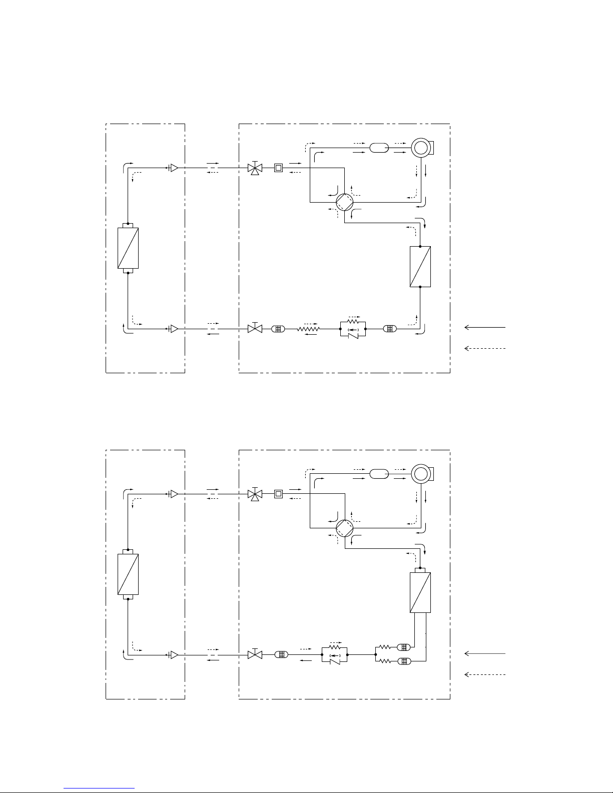
4.REFRIGERANT FLOW DIAGRAM
17
Indoor Unit MCAV77R5VAA Outdoor Unit GR79R5TBA
Compressor
4-way
valve
Accumulator
Wide tube
service
valve
Wide tube
O.D.
ø9.52 mm
(3/8 ")
Narrow
tube
service
valve
Narrow tube
O.D.
ø6.35 mm
(1/4")
Heat exchanger
Heat exchanger
Muffler
Capillary tube
Capillary tube
Cooling cycle
Heating cycle
Strainer
Indoor unit Outdoor unit
Check
valve
Indoor Unit MCAV97R5VAA Outdoor Unit GR99R5TBA
Compressor
4-way
valve
Accumulator
Wide tube
service
valve
Wide tube
O.D.
ø9.52 mm
(3/8 ")
Narrow
tube
service
valve
Narrow tube
O.D.
ø6.35 mm
(1/4")
Heat exchanger
Heat exchanger
Muffler
Capillary tube
Cooling cycle
Heating cycle
Strainer
Indoor unit Outdoor unit
Check
valve
Strainer
Capillary
tube
Strainer
Page 21
18
Insulation of Refrigerant Tubing
Because capillary tubing is used in the outdoor unit, both the
wide and narrow tubes of this air conditioner become cold. To
prevent heat loss and wet floors due to dripping of
condensation, both tubes must be well insulatedwith a
proper insulation material. The thickness of the insulation
should be a min. 8 mm.
After a tube has been insulated,
never try to bend it into a narrow
curve because it can cause the tube
to break or crack.
IMPORTANT
CAUTION
Wide tube
Thickness:
Min. 8 mm
Insulation
Narrow tube
Thickness:
Min. 8 mm
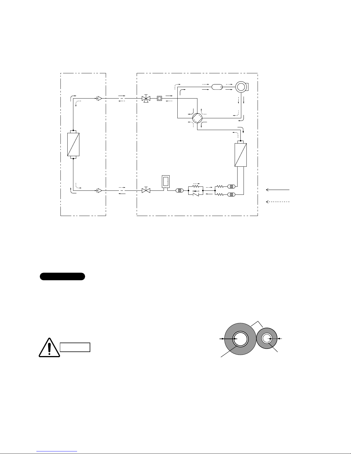
Indoor Unit MCAV127R5VAB- KPA128R5TAA Outdoor Unit GR129R5TBA
Compressor
4-way
valve
Accumulator
Wide tube
service
valve
Wide tube
O.D.
ø12.7 mm
(1/2 ")
Narrow
tube
service
valve
Narrow tube
O.D.
ø6.35 mm
(1/4")
Heat exchanger
Heat exchanger
Muffler
Capillary
Cooling cycle
Heating cycle
Strainer
Indoor unit Outdoor unit
Check
valve
Strainer
Capillary
tube
Accumulator
Page 22
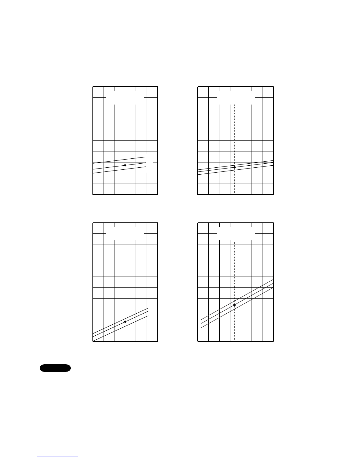
5.PERFORMANCE DATA
5-1.Performance charts
19
Indoor inlet air
D.B. temp. (°C)
1.38 (13)
1.28 (12)
1.18 (11)
1.08 (10)
0.98 ( 9 )
0.89 ( 8 )
0.79 ( 7 )
0.69 ( 6 )
25 30 35 40 45 50
Outdoor inlet air D.B. temp. (°C)
Low pressure at wide tube service valve MPa (kgf/cm
2
G)
0.59 ( 5 )
0.49 ( 4 )
0.39 ( 3 )
■ Cooling Characteristics ■ Heating Characteristics
Indoor inlet air
D.B. temp. (°C)
Indoor inlet air
D.B. temp. (°C)
9
8
7
6
5
4
3
2
1
25 30 35 40 45 50
Outdoor inlet air D.B. temp. (°C)
Operating current (A)
10
Indoor inlet air
D.B. temp. (°C)
8
7
6
5
4
3
2
1
–5 0 5 10 15 20
Outdoor inlet air D.B. temp. (°C)
Operating current (A)
25
9
10
7
32
27
19
27
20
15
2.95 (30)
2.85 (28)
2.65 (26)
2.46 (24)
2.26 (22)
2.06 (20)
–5 0 5 10 15 20
Outdoor inlet air D.B. temp. (°C)
High pressure at wide tube service valve MPa (kgf/cm
2
G)
1.87 (18)
1.67 (16)
1.47 (14)
25
7
1.28 (12)
1.08 (10)
32
27
19
27
20
15
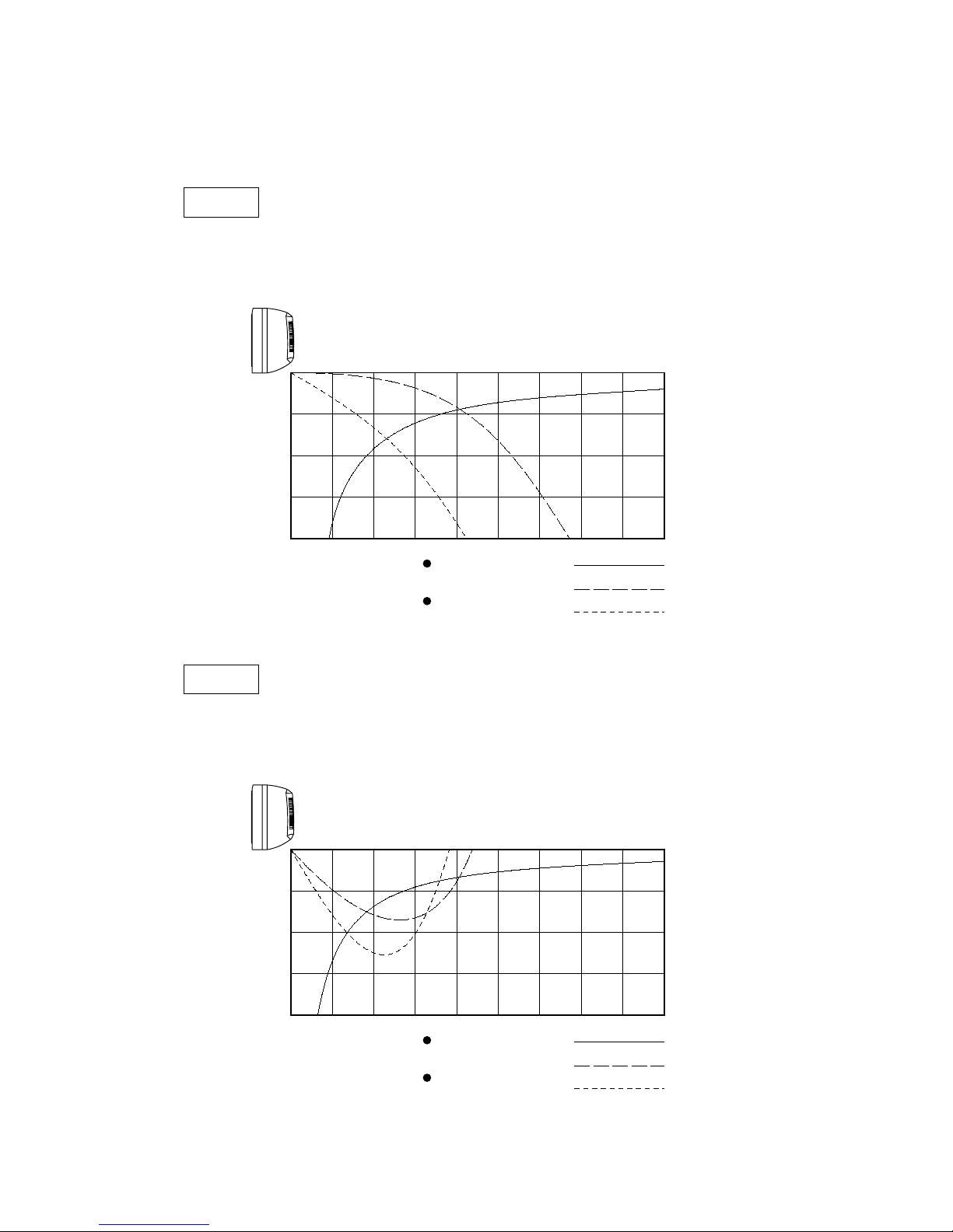
Overload prevention operates to protect the air conditioner when outdoor ambient temperature reaches extremely
high in heating mode. (Refer to “7-5 Overload prevention”)
● ...... Points of Rating condition
Black dots in above charts indicate the following rating conditions.
Cooling:Indoor air temperature 27°C D.B./19°C W.B. Heating:Indoor air temperature 20°C D.B.
Outdoor air temperature 35°C D.B./24°C W.B. Outdoor air temperature 7°C D.B./6°C W.B.
NOTE
Indoor Unit MCAV77R5VAA
Outdoor Unit GR79R5TBA
Page 23

20
Indoor inlet air
D.B. temp. (°C)
1.38 (13)
1.28 (12)
1.18 (11)
1.08 (10)
0.98 ( 9 )
0.89 ( 8 )
0.79 ( 7 )
0.69 ( 6 )
25 30 35 40 45 50
Outdoor inlet air D.B. temp. (°C)
Low pressure at wide tube service valve MPa (kgf/cm
2
G)
0.59 ( 5 )
0.49 ( 4 )
0.39 ( 3 )
■ Cooling Characteristics ■ Heating Characteristics
Indoor inlet air
D.B. temp. (°C)
Indoor inlet air
D.B. temp. (°C)
9
8
7
6
5
4
3
2
1
25 30 35 40 45 50
Outdoor inlet air D.B. temp. (°C)
Operating current (A)
10
Indoor inlet air
D.B. temp. (°C)
8
7
6
5
4
3
2
1
–5 0 5 10 15 20
Outdoor inlet air D.B. temp. (°C)
Operating current (A)
25
9
10
7
2.95 (30)
2.85 (28)
2.65 (26)
2.46 (24)
2.26 (22)
2.06 (20)
–5 0 5 10 15 20
Outdoor inlet air D.B. temp. (°C)
High pressure at wide tube service valve MPa (kgf/cm
2
G)
1.87 (18)
1.67 (16)
1.47 (14)
25
7
1.28 (12)
1.08 (10)
32
27
19
27
20
15
32
27
19
27
20
15
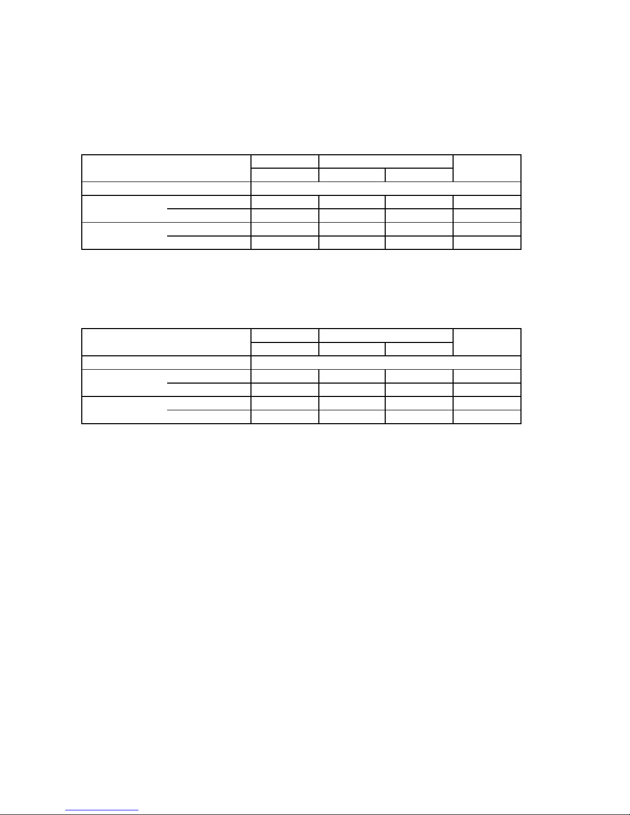
Overload prevention operates to protect the air conditioner when outdoor ambient temperature reaches extremely
high in heating mode. (Refer to “7-5 Overload prevention”)
● ...... Points of Rating condition
Black dots in above charts indicate the following rating conditions.
Cooling:Indoor air temperature 27°C D.B./19°C W.B. Heating:Indoor air temperature 20°C D.B.
Outdoor air temperature 35°C D.B./24°C W.B. Outdoor air temperature 7°C D.B./6°C W.B.
NOTE
Indoor Unit MCAV99R5VAA
Outdoor Unit GR99R5TBA
Page 24

21
Indoor inlet air
D.B. temp. (°C)
1.38 (13)
1.28 (12)
1.18 (11)
1.08 (10)
0.98 ( 9 )
0.89 ( 8 )
0.79 ( 7 )
0.69 ( 6 )
25 30 35 40 45 50
Low pressure at wide tube service valve MPa (kgf/cm
2
G)
0.59 ( 5 )
0.49 ( 4 )
0.39 ( 3 )
■ Cooling Characteristics ■ Heating Characteristics
Indoor inlet air
D.B. temp. (°C)
Indoor inlet air
D.B. temp. (°C)
11
10
9
8
7
6
5
4
3
25 30 35 40 45 50
Outdoor inlet air D.B. temp. (°C)
Operating current (A)
12
Indoor inlet air
D.B. temp. (°C)
10
9
8
7
6
5
4
3
–5 0 5 10 15 20
Outdoor inlet air D.B. temp. (°C)
Operating current (A)
25
11
12
7
32
27
19
32
27
19
27
20
15
–5 0 5 10 15 20
Outdoor inlet air D.B. temp. (°C)
High pressure at wide tube service valve MPa (kgf/cm
2
G)
25
7
2.95 (30)
2.85 (28)
2.65 (26)
2.46 (24)
2.26 (22)
2.06 (20)
1.87 (18)
1.67 (16)
1.47 (14)
1.28 (12)
1.08 (10)
27
20
15
Overload prevention operates to protect the air conditioner when outdoor ambient temperature reaches extremely
high in heating mode. (Refer to “7-5 Overload prevention”)
● ...... Points of Rating condition
Black dots in above charts indicate the following rating conditions.
Cooling:Indoor air temperature 27°C D.B./19°C W.B. Heating:Indoor air temperature 20°C D.B.
Outdoor air temperature 35°C D.B./24°C W.B. Outdoor air temperature 7°C D.B./6°C W.B.
NOTE
Indoor Unit MCAV127R5VAB KPA128R5TAA
Outdoor Unit GR129R5TBA
Outdoor inlet air D.B. temp. (°C)
Page 25
22
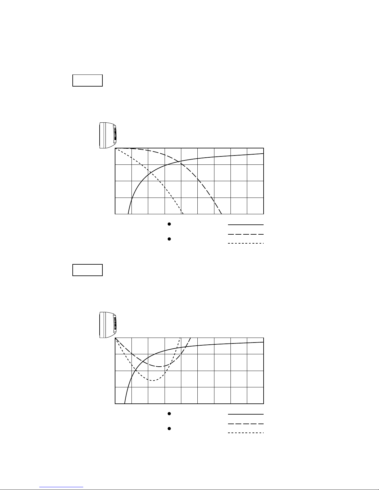
5-2.Air Throw Distance Chart
Indoor Unit MCAV77R5VAA
0
123456789
1
2
3
4
Horizontal distance (m)
Axis air velocity (m/s)
Vertical distance (m)
Axis air velocity
Flap angle
0°
30°
Room air temp.: 27°C
Fan speed : High
Cooling
0
123456789
1
2
3
4
Horizontal distance (m)
Axis air velocity (m/s)
Vertical distance (m)
Axis air velocity
Flap angle
45°
60°
Room air temp.: 20°C
Fan speed : High
Heating
Page 26

23
Indoor Unit MCAV97R5VAA
0
123456789
1
2
3
4
Horizontal distance (m)
Axis air velocity (m/s)
Vertical distance (m)
Axis air velocity
Flap angle
45°
60°
Room air temp.: 20°C
Fan speed : High
Heating
0
123456789
1
2
3
4
Horizontal distance (m)
Axis air velocity (m/s)
Vertical distance (m)
Axis air velocity
Flap angle
0°
30°
Room air temp.: 27°C
Fan speed : High
Cooling
Page 27
24
Indoor Unit MCAV127R5VAB
0
123456789
1
2
3
4
Horizontal distance (m)
Axis air velocity (m/s)
Vertical distance (m)
Axis air velocity
Flap angle
45°
60°
Room air temp.: 20°C
Fan speed : High
Heating
0
123456789
1
2
3
4
Horizontal distance (m)
Axis air velocity (m/s)
Vertical distance (m)
Axis air velocity
Flap angle
0°
30°
Room air temp.: 27°C
Fan speed : High
Cooling
Page 28

25
Indoor Unit KPA128R5TAA
Room air temp. : 27°C
Fan speed : High
Cooling
Room air temp. : 20°C
Fan speed : High
Heating
01234567
1
0
2
3
Horizontal distance (m)
Axis air velocity (m/s)
Vertical distance (m)
Axis air verocity
Flap angle
45°
30°
Ceiling mounted
01234567
1
0
2
3
Horizontal distance (m)
Axis air velocity (m/s)
Vertical distance (m)
Axis air verocity
Flap angle
60°
80°
Page 29

5-3. Heating Capacity
–5 0 5
7
10 15
Outdoor temperature (°C DB)
0
10
20
30
40
50
60
70
80
90
100
110
120
Heating capacity ratio (%)
NOTE
1) … Point of Rating condition
Black dot in the chart indicate the following rating condition.
Indoor : 20°C D.B.
Outdoor : 7°C D.B. / 6°C W.B.
2) Above characteristics indicate instantaneous operation, which does not take into
consideration defrost operation.
3) Fan speed : High
4) Because this air conditioner heats a room by drawing in the heat of the outside
air (heat pump system), the heating efficiency will fall off when the outdoor
temperature is very low. If sufficient heat cannot be obtained with this air
conditioner, use another heating appliance in conjunction with it.
–8
26
Page 30

27
6.ELECTRICAL DATA
6-1.Electrical Characteristics
Indoor Unit MCAV77R5VAA
Outdoor Unit GR79R5TBA
COOLING
Indoor Unit Outdoor Unit Complete Unit
Fan Motor Fan Motor Compressor
Performance at 230V 1-phase 50Hz
Rating Conditions Running Amps. A 0.11 0.24 3.35 3.7
Power Input kW 0.025 0.055 0.710 0.790
Full Load ConditionsRunning Amps. A 0.11 0.24 4.05 4.4
Power Input kW 0.025 0.055 0.89 0.97
Rating Conditions : Indoor Air Temperature 27°C D.B. / 19°C W.B.
Outdoor Air Temperature 35°C D.B.
Full Load Conditions: Indoor Air Temperature 32°C D.B. / 23°C W.B.
Outdoor Air Temperature 43°C D.B.
HEATING
Indoor Unit Outdoor Unit Complete Unit
Fan Motor Fan Motor Compressor
Performance at 230V 1-phase 50Hz
Rating Conditions Running Amps. A 0.11 0.24 3.15 3.5
Power Input kW 0.025 0.055 0.671 0.75
Full Load ConditionsRunning Amps. A 0.11 0.24 3.2 3.55
Power Input kW 0.025 0.055 0.690 0.770
Rating Conditions : Indoor Air Temperature 20°C D.B.
Outdoor Air Temperature 7°C D.B. / 6°C W.B.
Full Load Conditions: Indoor Air Temperature 27°C D.B.
Outdoor Air Temperature 24°C D.B. / 18°C W.B.
Page 31

28
Indoor Unit MCAV97R5VAA
Outdoor Unit GR99R5TBA
COOLING
Indoor Unit Outdoor Unit Complete Unit
Fan Motor Fan Motor Compressor
Performance at 230V 1-phase 50Hz
Rating Conditions Running Amps. A 0.12 0.24 4.05 4.4
Power Input kW 0.027 0.055 0.888 0.97
Full Load ConditionsRunning Amps. A 0.12 0.24 4.74 5.1
Power Input kW 0.027 0.055 1.068 1.15
Rating Conditions : Indoor Air Temperature 27°C D.B. / 19°C W.B.
Outdoor Air Temperature 35°C D.B.
Full Load Conditions: Indoor Air Temperature 32°C D.B. / 23°C W.B.
Outdoor Air Temperature 43°C D.B.
HEATING
Indoor Unit Outdoor Unit Complete Unit
Fan Motor Fan Motor Compressor
Performance at 230V 1-phase 50Hz
Rating Conditions Running Amps. A 0.12 0.24 3.85 4.2
Power Input kW 0.027 0.055 0.868 0.95
Full Load ConditionsRunning Amps. A 0.12 0.24 4.19 4.55
Power Input kW 0.027 0.055 0.925 1.007
Rating Conditions : Indoor Air Temperature 20°C D.B.
Outdoor Air Temperature 7°C D.B. / 6°C W.B.
Full Load Conditions: Indoor Air Temperature 27°C D.B.
Outdoor Air Temperature 24°C D.B. / 18°C W.B.
Page 32

29
Indoor Unit MCAV127R5VAB
Outdoor Unit GR129R5TBA
COOLING
Indoor Unit Outdoor Unit Complete Unit
Fan Motor Fan Motor Compressor
Performance at 230V 1-phase 50Hz
Rating Conditions Running Amps. A 0.13 0.28 5.39 5.8
Power Input kW 0.031 0.062 1.177 1.27
Full Load ConditionsRunning Amps. A 0.13 0.28 6.79 7.2
Power Input kW 0.031 0.062 1.507 1.60
Rating Conditions : Indoor Air Temperature 27°C D.B. / 19°C W.B.
Outdoor Air Temperature 35°C D.B.
Full Load Conditions: Indoor Air Temperature 32°C D.B. / 23°C W.B.
Outdoor Air Temperature 43°C D.B.
HEATING
Indoor Unit Outdoor Unit Complete Unit
Fan Motor Fan Motor Compressor
Performance at 230V 1-phase 50Hz
Rating Conditions Running Amps. A 0.13 0.28 5.99 6.4
Power Input kW 0.031 0.062 1.327 1.42
Full Load ConditionsRunning Amps. A 0.13 0.28 7.09 7.5
Power Input kW 0.031 0.062 1.557 1.650
Rating Conditions : Indoor Air Temperature 20°C D.B.
Outdoor Air Temperature 7°C D.B. / 6°C W.B.
Full Load Conditions: Indoor Air Temperature 27°C D.B.
Outdoor Air Temperature 24°C D.B. / 18°C W.B.
Page 33
Indoor Unit KPA128R5TAA
Outdoor Unit GR129R5TBA
COOLING
Indoor Unit Outdoor Unit Complete Unit
Fan Motor Fan Motor Compressor
Performance at 230V 1-phase 50Hz
Rating Conditions Running Amps. A 0.29 0.28 5.03 5.6
Power Input kW 0.07 0.062 1.088 1.22
Full Load Conditions Running Amps. A 0.29 0.28 6.43 7.0
Power Input kW 0.07 0.062 1.388 1.52
Rating Conditions : Indoor Air Temperature 27°C D.B. / 19°C W.B.
Outdoor Air Temperature 35°C D.B.
Full Load Conditions : Indoor Air Temperature 32°C D.B. / 23°C W.B.
Outdoor Air Temperature 43°C D.B.
HEATING
Indoor Unit Outdoor Unit Complete Unit
Fan Motor Fan Motor Compressor
Performance at 230V 1-phase 50Hz
Rating Conditions Running Amps. A 0.29 0.28 5.53 6.1
Power Input kW 0.07 0.062 1.188 1.32
Full Load Conditions Running Amps. A 0.29 0.28 7.43 8.0
Power Input kW 0.07 0.062 1.578 1.71
Rating Conditions : Indoor Air Temperature 20°C D.B.
Outdoor Air Temperature 7°C D.B. / 6°C W.B.
Full Load Conditions : Indoor Air Temperature 27°C D.B.
Outdoor Air Temperature 24°C D.B. / 18°C W.B.
30
Page 34
31
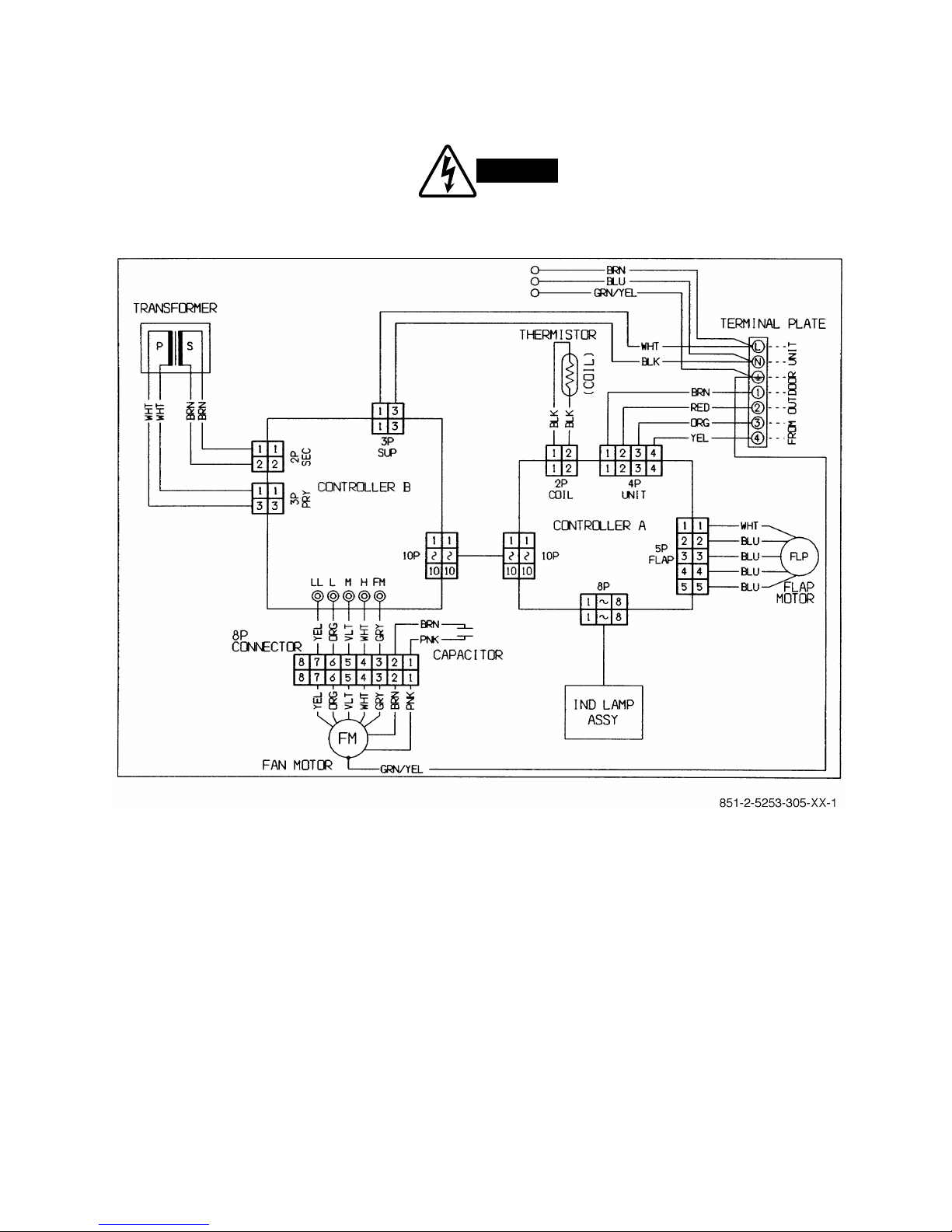
6-2.Electric Wiring Diagrams
To avoid electrical shock hazard, be sure to
disconnect power before checking, servicing
and/or cleaning any electrical parts.
WARNING
Indoor Unit MCAV77R5VAA
MCAV97R5VAA
MCAV127R5VAB
Page 35
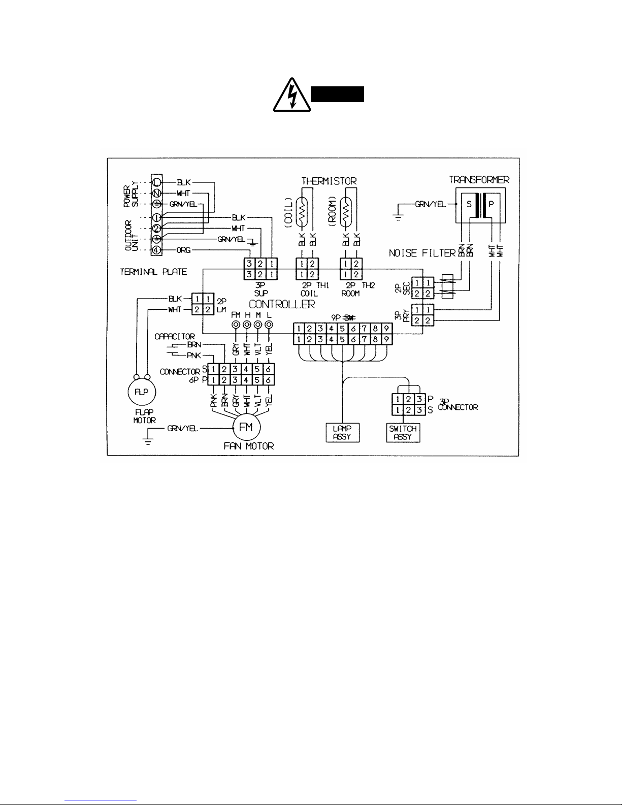
To avoid electrical shock hazard, be sure to
disconnect power before checking, servicing
and/or cleaning any electrical parts.
WARNING
Indoor Unit KPA128R5TAA
.
32
Page 36

33
To avoid electrical shock hazard, be sure to
disconnect power before checking, servicing
and/or cleaning any electrical parts.
WARNING
Outdoor Unit GR79R5TBA
GR99R5TBA
GR129R5TBA
Page 37
7.FUNCTION
7-1.Room Temperature Control
■
Cooling
●
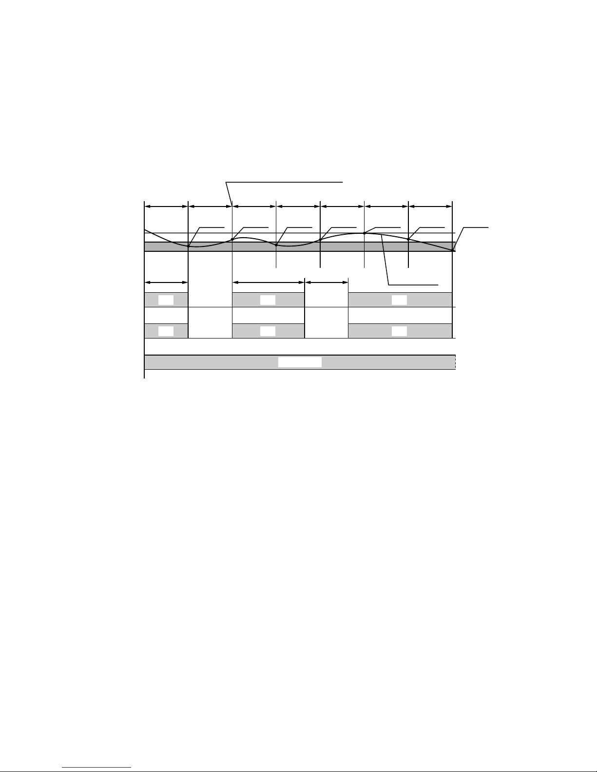
Room temperature control is obtained by cycling the compressor ON and OFF under control of the room
temperature sensor in the remote control unit.
●
The room temperature (and other information) is transmitted every 3 minutes by the remote control unit to the
controller in the indoor unit.
●
The control circuit will not attempt to turn the compressor ON until the compressor has been OFF for at least
3 minutes. To protect the compressor from stalling out when trying to start against the high side refrigerant
pressure, the control circuit has a built-in automatic time delay to allow the internal pressure to equalize.
●
As a protective measure, the control circuit switches the compressor OFF after 5 minutes or more of compressor
operation.
●
Thermo. ON :When the room temperature is above T + 1°C (T°C is set temperature).
Compressor ➞ON
●
Thermo. OFF :When the room temperature is equal to or below set temperature T°C.
Compressor ➞OFF
3 minutes 3 minutes 3 minutes 3 minutes 3 minutes 3 minutes 3 minutes
3 minutes5 minutes
ON OFF ON OFF ON OFFCompressor
ON OFF ON OFF ON OFF
More than
5 minutes
Outdoor fan
Indoor fan
Set speed
T+1 °C
T °Cset temp.
Thermo.
OFF
Thermo.
OFF
Thermo.
ON
Thermo.
OFF
Thermo.
ON
Thermo.
ON
Thermo.
ON
Room temp.
Signal from remote control unit
34
Page 38

■
Heating
●
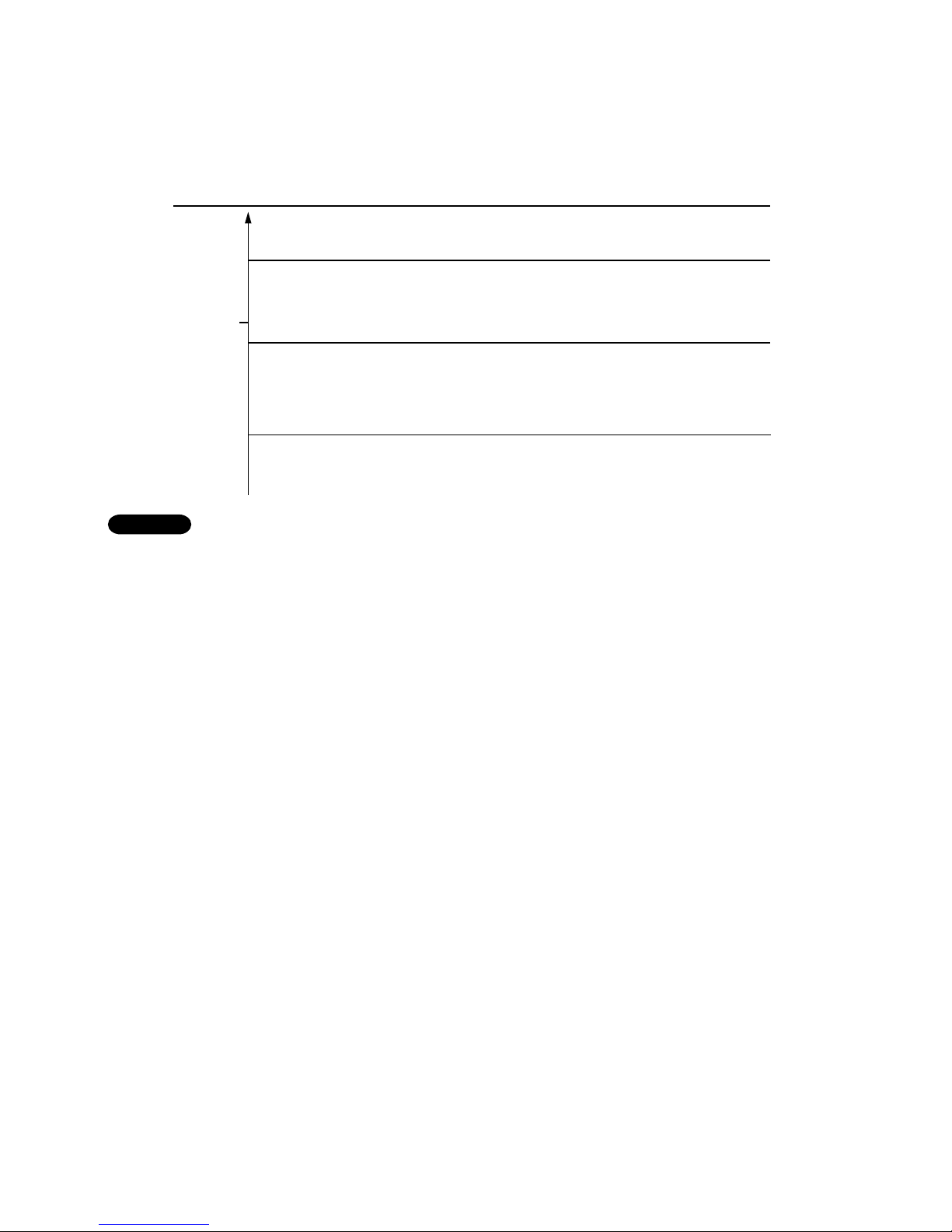
Room temperature control is obtained by cycling the compressor ON and OFF under control of the room
temperature sensor in the remote control unit.
●
The room temperature (and other information) is transmitted every 3 minutes by the remote control unit to the
controller in the indoor unit.
●
The control circuit will not attempt to turn the compressor ON until the compressor has been OFF for at least 5
minutes. To protect the compressor from stalling out when trying to start against the high side refrigerant
pressure, the control circuit has a built-in automatic time delay to allow the internal pressure to equalize.
●
As a protective measure, the control circuit switches the compressor OFF after 5 minutes or more of compressor
operation.
●
Thermo. ON : When the room temperature is below T – 1°C (T°C is set temperature).
Compressor ➞ON
●
Thermo. OFF : When the room temperature is equal to or above set temperature T°C.
Compressor ➞OFF
*1: Refer to "8-6 Cold Draft Prevention".
NOTE
3 minutes 3 minutes 3 minutes 3 minutes 3 minutes 3 minutes
5 minutes 5 minutes
ON OFF ONOFFCompressor OFF
ON OFF ONOFFOutdoor fan OFF
Set speed
LL
LL
ON
OFF
OFF OFF ON OFF ON
*1
OFF
OFF
ON
ON(Reversing cycle)
Thermo.ONThermo.
OFF
Thermo.
ON
Thermo.
OFF
More than
5 minutes
Signal from remote control unit
T °C
T–1 °C
T–2 °C
set temp.
Indoor fan
Standby lamp
Indoor heat exch.
coil temp.
Tc °C
Solenoid coil
(4–way valve)
Operation button
Room temp.
*1
Set speed
30 seconds30 seconds
Max. 10minutes
OFF
35
Page 39
7-2.Dry Operation (Dehumidification)
●
Dry operation uses the ability of the cooling cycle to remove moisture from the air, but by running at low level to
dehumidify without greatly reducing the room temperature. The air conditioner repeats the cycle of turning ON
and OFF automatically as shown in the chart below according to the room temperature.
●Intermittent ventilation occurs by switching the indoor fan speed between L ↔LL.
●Dry operation does not occur when the room temperature is under 15°C, which is the monitor zone.
●When the compressor stops, the indoor fan stops as well.
7-3.Automatic Switching between Cooling and Heating
●
When AUTO mode is selected, the microprocessor calculates the difference between the set temperature and
the room temperature, and automatically switches to COOLING or HEATING mode to maintain the desired
temperature.
Room temp. ≥Set temp. ➞COOL
Room temp. < Set temp. ➞HEAT
This means that if the room temperature is higher thanor equal tothe set temperature, COOLINGoperation
begins. If the room temperature is lower thanthe set temperature, HEATINGoperation begins.
NOTE
Room temp.
Cooling operation
T+2 °C
Set temp.T °C
T–1 °C
Monitor zone
Both the indoor and outdoor units stop.
Room temp. 15 °C
*Dry A zone
Compressor :
FMI (indoor fan) :
Continuous operation
L (low speed) / LL (very low speed) intermittent ventilation
only while the compressor is ON.
*Dry B zone
Compressor :
FMI (indoor fan) :
Intermittent operation (ON for 3 minutes and OFF for 9 minutes)
L (low speed) / LL (very low speed) intermittent ventilation
only while the compressor is ON.
36
Page 40
7-4.Freeze Prevention (Cooling)
●
This function prevents freezing of the indoor heat exchange coil.
●
When the compressor has been running for 10 minutes
*1)
or more and the temperature of the indoor heat
exchange coil falls below –1°C, the control circuit stops the compressor for at least 6 minutes. The compressor
does not start again until the temperature rises above 8°C or 6 minutes has elapsed.
*1)Functionally, compressor running period, or time are of two types, 10 minutes and 6 minutes depending upon
production date.
NOTE
ON ON ON ON
OFFOFF
Set speed
More than
10 minutes
6 minutes
T+1 °C
Indoor heat exch.
coil temp.
–1 °C
Compressor
Indoor fan
Room temp.
Thermo. OFF
Thermo. ON
Set temp.T °C
More than
10 minutes
More than
6 minutes
Set speed
*1) *1)
37
Page 41
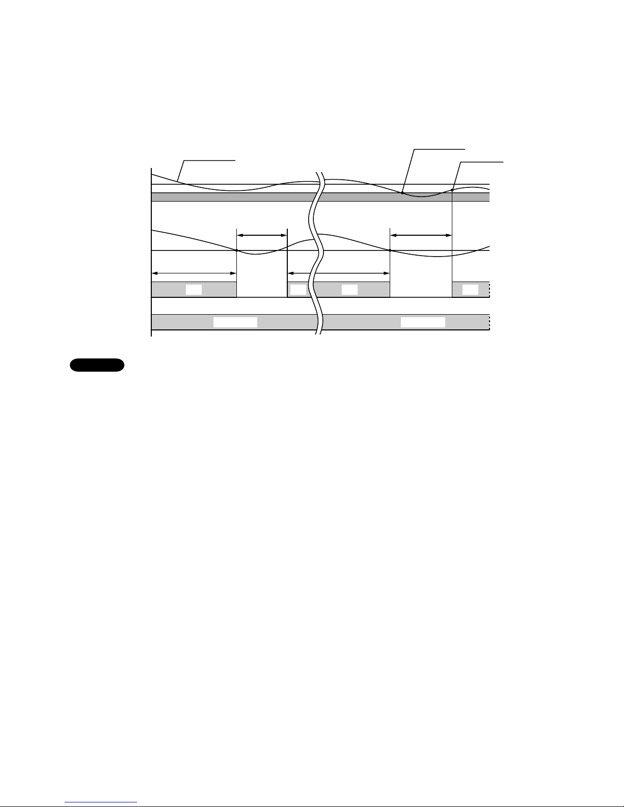
7-5.Overload Prevention (Heating)
●
This function prevents overheating of the indoor heat exchange coil.
●
When the temperature of the indoor heat exchange coil rises above B°C, and if the indoor fan is L (low speed),
then the fan speed changes from L (low speed) to M (medium speed).
●
When the temperature of the indoor heat exchange coil rises above A°C, the outdoor fan stops.
The operation temperature shown as A, B, Cand Din the chart differ by models.
NOTE
ONON OFF
ON
H or M or L H ➞ H, M ➞ M, L ➞ M
A
B
C
D
Indoor heat
exch. coil
temp. °C
Outdoor fan
Indoor fan
Compressor
38
MCAV77R5VAA MCAV97R5VAA MCAV127R5VAB
A 50°C 54°C 58°C
B 49°C 52°C 56°C
C 42°C 45°C 50°C
D 39°C 42°C 46°C
Page 42

7-6.Cold Draft Prevention (Heating)
●
This function controls indoor fan speed so a strong draft of cold air will not blow out before the indoor heat
exchange coil have sufficiently warmed up.
●
STANDBY lamp on front of the indoor unit lights up when this function is working.
●
when 10 minutes has elapsed,the fan speed is automatically switched to set speed regardless of indoor heat
exchange coil temperature.
The operation temperature shown as Tcin the chart differ by models.
NOTE
OFF
ON
OFF
Set speed
Indoor fan
Standby lamp
Indoor heat exch.
coil temp. (°C)
Tc
Max. 10minutes
39
MCAV77R5VAA MCAV97R5VAAMCAV127R5VAB
Tc 32°C 33°C 34°C
Page 43
7-7.Defrosting Operation (Heating)
■ Defrosting Flowchart
Compressor ON
Indoor heat exchanger coil
temperature drops 0.8°C per
6 minutes and it repeats
3 times in succession.
Integrated operating time of
compressor is more than
3 hours.
Defrosting begins.
Cold-draft prevention
Temperature of outdoor heat
exchange coil is higher than
12°C.
Release of defrosting
Indoor fan runs at set speed
when temperature of indoor
heat exchanger reads Tc °C.
B
Defrosting time is over 12
minutes.
No LL fan operation during this period.
Compressor keeps running
for at least 6 minutes.
Temperature of outdoor heat
exchanger coil is below 9°C.
Integrated operating time of
compressor is more than 1.5
hours.
Thermo. OFF.
(Compressor OFF)
CD
Temperature of indoor heat
exchanger coil is below
Ta°C.
Continuous operating time of
compressor is more than 20
minutes.
Outdoor fan is either operated
or stopped for more than 10
minutes.
A
Is outdoor fan continuously
operating for more than 10
minutes?
Integrated operating time of
compressor is more than 50
minutes.
Temperature of indoor heat
exchanger coil is below
Ta+
13°C
. (See table below.)
Temp. of indoor heat exch.
coil immediately before thermo
goes off is either below
Ta + 4°C or Tb + 4°C (when
overload prevention works).
NO
NO
NO
YES
YES
YES
Overload
prevention works.
Does outdoor fan
stop?
Compressor keeps running for
at least 6 minutes.
Release of overload prevention
(Outdoor fan operates.)
Compressor keeps running for
at least 6 minutes.
NOTE
NOTE
The values shown as Ta, Tb and Tc
differ according to the models.
MCAV77R5VAA
Ta
Tb
Tc
*1
*2
*3
35
48
32
38
51
33
44
57
34
MCAV97R5VAA
MCAV129R5VAB
*1
*1
*3
*1 & *2
40
Page 44

■ Defrosting Mode Timing Chart
41
ON
ON
ON ON ON
ON
ONON
Set speed
OFF
OFF
OFF
OFF
32 seconds 11 minutes 32 seconds
Start of defrosting
Release of defrosting
OFF
OFF
Release of
cold draft prevention
Compressor
Outdoor fan
Solenoid coil
(4–way valve)
Indoor fan
Standby lamp
Indoor heat
exch. coil
temp.
ONON
Set speed
* 1
2 seconds 2 seconds
Tc°C
NOTE
*1: Refer to "8-6 Cold Draft Prevention".
Page 45

8.TROUBLESHOOTING
8-1.Check before and after troubleshooting
8-1-1.Check power supply wiring.
●
Check that power supply wires are correctly connected to terminalsLand Non the terminal plate in the indoor
unit.
8-1-2.Check inter-unit wiring.
●
Check that inter-unit wiring is correctly connected to the outdoor unit from the indoor unit.
8-1-3.Check power supply.
●
Check that voltage is in specified range (±10% of the rating).
●
Check that power is being supplied.
8-1-4.Check lead wires and connectors in indoor and outdoor units.
●
Check that coating of lead wires is not damaged.
●
Check that lead wires and connectors are firmly connected.
●
Check that wiring is correct.
Outdoor
unit
Indoor
unit
Power supply :
Single phase
220–240V ~ 50Hz
Ground
Ground
Inter–unit
power wiring
Power plug
(Local supply)
Inter–unit
control wiring
L
1
2
3
4
L
1
2
3
4
NN
42
WARNING
Hazardous voltage can cause ELECTRIC SHOCK or
DEATH. Disconnect power or turn off circuit breaker
before you start checking or servicing.
Page 46

8-2.Air conditioner does not operate.
8-2-1.Circuit breaker trips (or fuse blows).
A. When the circuit breaker is set to ON, it is tripped soon. (Resetting is not possible.)
●
There is a possibility of ground fault.
●
Check insulation resistance.
If resistance value is 2MΩor less, insulation is defective (“NO”).
NO
Measure insulation
resistance of electrical
parts in outdoor unit.
NO
Set circuit breaker to OFF.
*
Measure insulation
resistance of electrical
parts in indoor unit.
1
Remove inter-unit wires from
terminal plate in outdoor unit.
Measure insulation resistance
of outdoor unit.
•
2
Remove inter-unit wires from
terminal plate in indoor unit.
Then, pull the power plug out of
the wall outlet
Measure insulation resistance
of indoor unit.
•
•
•
Insulation of
outdoor unit
is defective.
Insulation of
indoor unit
is defective.
WARNING
LL
NN
1
2
3
4
1
2
3
4
Outdoor
unit
1
Indoor
unit
22
Inter–unit
wiring
Circuit
breaker
Ground
Ground
Power plug
(Local supply)
Wall outlet
(receptacle)
Single phase
220–240V ~ 50Hz
43
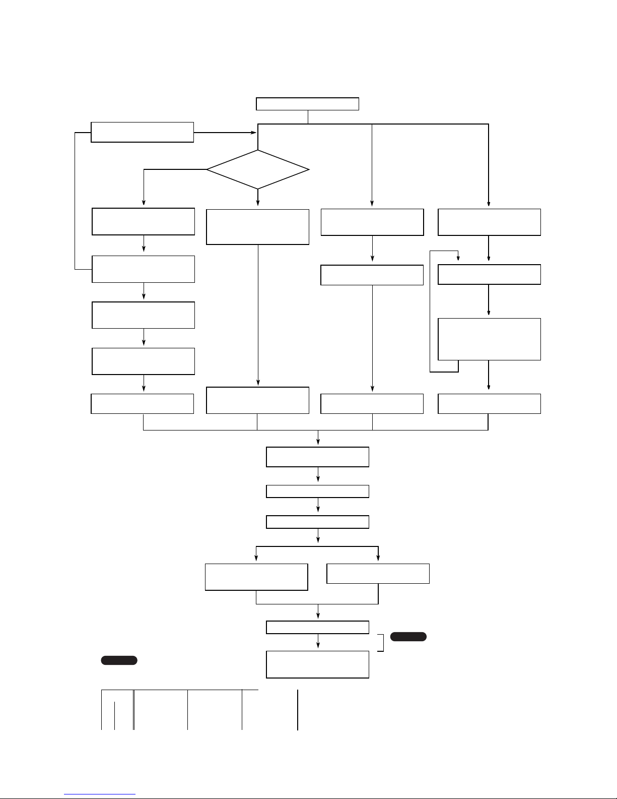
Page 47

B. Circuit breaker trips in several minutes after turning the air conditioner on.
●
There is a possibility of short circuit.
8-2-2.Neither indoor nor outdoor unit runs.
A. Power is not supplied.
B. Check "OPERATION selector" switch in the indoor unit.
YES
NO
•
OPERATION selector switch is set
in ON position.
Set OPERATION selector switch
to ON.
Indoor PCB Ass'y is defective.
NO
•
Check power supply.
Power is being supplied to the
indoor unit.
Circuit breaker
is tripped.
Power failure
Reset breaker.
Wait for recovery
or contact power
company.
Replace with suitable
one (larger capacity).
•
•
•
NO
Check capacity of circuit breaker.
Capacity of circuit breaker is
suitable.
Measure resistance of outdoor fan
motor winding.
Measure resistance of compressor
motor winding.
•
Measure resistance of 4-way valve's
winding.
In case of Heating operation :
44
Page 48
C. Check remote control unit.
D. Check fuse on the indoor PCB Ass'y.
E. Check TIMER on the remote control unit.
•
Timer is turned ON. Check to see
if or is displayed on
remote control
YES
Cancel the timer mode.
ON
OK
OK
•
Check fuse on indoor PCB Ass'y
for continuity. (F)
•
Check operation lamp to see
if light is ON.
Light is OFF
•
Measure resistance of primary and
secondary winding of transformer.
(TR)
•
Indoor PCB Ass'y is defective.
OK
OK
•
Measure resistance of indoor and
outdoor fan motor winding.
(FM)
•
Measure resistance of compressor
motor winding. (CM)
OK
•
Measure coil resistance of power
relay in outdoor unit.
(PR)
•
Replace the fuse.
If fuse has been blown,
OK
•
Try to run with another remote
control unit.
First remote control unit is defective.
•
Check for residue buildup on
transmitter of remote control unit.
•
Check for residue buildup on remote
control receiver on front of indoor
unit.
Clean transmitter.
Clean receiver.
45
Page 49

8-2-3.Only outdoor unit does not run.
A. Check setting temperature.
B. Check PCB Ass'y in either indoor or outdoor unit.
8-2-4.Only Indoor unit does not run.
•
Indoor PCB Ass'y is defective.
•
Indoor PCB Ass'y is defective.
•
Check voltage between terminals
No. 1(+) and No. 2 at the terminal
plate. (DC 24V)
No voltage appears.
•
Outdoor PCB Ass'y is defective.
OK
OK
NO
Is room temperature too low ?
Try to lower setting temperature by
temperature setting button ( button).
Outdoor unit still does
not run.
Remote control unit is defective.
•
Try to run using another remote
control unit.
COOL
OK
NO
Is room temperature too high ?
Try to raise setting temperature by
temperature setting button ( button).
Outdoor unit still does
not run.
•
Try to run using another remote
control unit.
HEAT
Remote control unit is defective.
46
Page 50
8-3.Some part of air conditioner does not operate.
8-3-1.Only indoor fan does not run.
8-3-2.Only flap motor does not run.
8-3-3.Only outdoor fan does not run.
Fan cannot
be turned.
OK
•
Check fan rotation.
Turn fan gently once or twice by
hand.
•
Check fan casing
foreign matter on
inside.
Fan motor burnout
or foreign matter in
bearings.
Remove foreign
matter or repair.
Repair or replace.
•
Measure resistance of outdoor fan
motor winding.
•
Check fan motor capacitor.
•
Measure resistance of flap motor
winding.
Fan cannot
be turned.
OK
•
Check fan rotation.
Turn fan gently once or twice by
hand.
•
Check fan casing
foreign matter on
inside.
Fan motor burnout
or foreign matter in
bearings.
Remove foreign
matter or repair.
Repair or replace.
•
Measure resistance of indoor fan
motor winding.
•
Check fan motor capacitor.
47
Page 51

8-3-4.Only compressor does not run.
•
Check compressor motor
capacitor.
•
Measure resistance of
compressor motor winding.
•
Measure resistance of power
relay. (PR)
NO
YES
YES
Internal protector (K)
is working.
YES
Temperature of compressor
is abnormally high.
Refrigerant gas shortage. Charge refrigerant gas (R22).
Rotor may be locked up.
(C1)
•
Measure Power supply
voltage.
The voltage is too low.
No
48
Page 52

8-4.Air conditioner operates, but abnormalities are observed.
8-4-1.Operation does not switch from HEAT to COOL (or COOL to HEAT).
•
Indoor PCB Ass'y is defective.
•
Check voltage between terminals
No. 1(+) and No. 3 at the terminal
plate. (DC 24V)
No voltage appears.
Outdoor PCB Ass'y is defective.
OK
•
Remote control unit may be defective.
•
Measure resistance of 4–way valve's
winding.
Receiver in lamp Ass'y may be
defective.
COOL ➞ HEAT
•
Check voltage between terminals
No. 1(+) and No. 3 at the terminal
plate. (0V)
HEAT ➞ COOL
49
Page 53

8-4-2.Poor cooling or heating.
8-4-3.Excessive cooling or heating.
NO
NO
•
Set temperature is suitable.
Set temperature to higher or
lower value using temperature
setting buttons of the remote
control unit.
•
Remote control unit is placed where
it can detect room temperature
properly.
Change position of remote
control unit.
Air filter is clogged.
NO
YES
Temperature
difference
is small.
YES
Temperature difference between
suction and discharge air is
large enough (approx. 10 deg. or more).
Possibility of
gas shortage.
YES
•
Check position of remote control unit.
Cool or warm air from air conditioner
reaches position directly.
•
Change position of remote
control unit.
•
Wide and narrow tubes between
indoor unit and outdoor unit are
insulated.
Insulate both wide and narrow
tubes separately and then
tape together.
•
Measure temperature of suction and
discharge air of air conditioner.
Charge refrigerant
gas (R22).
Check for clogging of air filter.
•
Fan speed is set to LOW.
Clean filter.
Set fan speed to either
HIGH or MEDIUM.
•
Review cooling load estimate,
if performance of air conditioner is
normal.
Reduce cooling or heating
load or replace the air
conditioner with larger
capacity.
50
Page 54

8-5.If a sensor is defective.
8-5-1.Indoor coil temp. thermistor (TH1) is defective.
Alarm Signal (*)
Operation lamp on the front side of the indoor unit will flash on and off when the indoor coil thermistor is defective.
At the same time the outdoor unit will stop. Indoor unit will operate only for ventilation.
8-5-2.Room temp. thermistor (TH2) is defective.
A. Open
When thermistor opens, the air conditioner will be in the following conditions as the controller tries to detect
extremely low room temperature.
a) In Cooling mode:The air conditioner soon stops and will not start again.
(Thermo.OFF) Neither outdoor fan nor compressor runs.
b) In Heating mode:The air conditioner continues to operate (Thermo.ON). Both
the outdoor fan and compressor do not stop. As a result, the
room becomes too warm.
B. Short
When thermistor is short, the air conditioner will be in the following conditions as
the controller tries to detect extremely high room temperature.
a) In Cooling mode:The air conditioner continues to operate (Thermo.ON). Both
the outdoor fan and compressor do not stop. As a result, the
room becomes too cold.
b) In Heating mode:The air conditioner soon stops and will not start again
(Thermo.OFF). Neither outdoor fan nor compressor runs.
Definition of Open or Short Circuit of Sensor (Thermistor)
Open ...A lead wire is broken or disconnected or the circuit inside the temperature sensor is open .
Short ...The protective cover of a lead wire has been damaged, and the exposed wire is touching another metal
part, or both lead wires have become exposed and are touching each other. Alternatively, the circuit
inside the temperature sensor is closed.
NOTE
NOTE
•
Operation lamp on front side of
indoor unit is flashing on and off. (*)
YES
•
Replace thermistor.
•
Thermistor (TH1 ) is defective.
YES
51
Temperature
sensor
Lead
wires
Thermistor Structure
Page 55
52
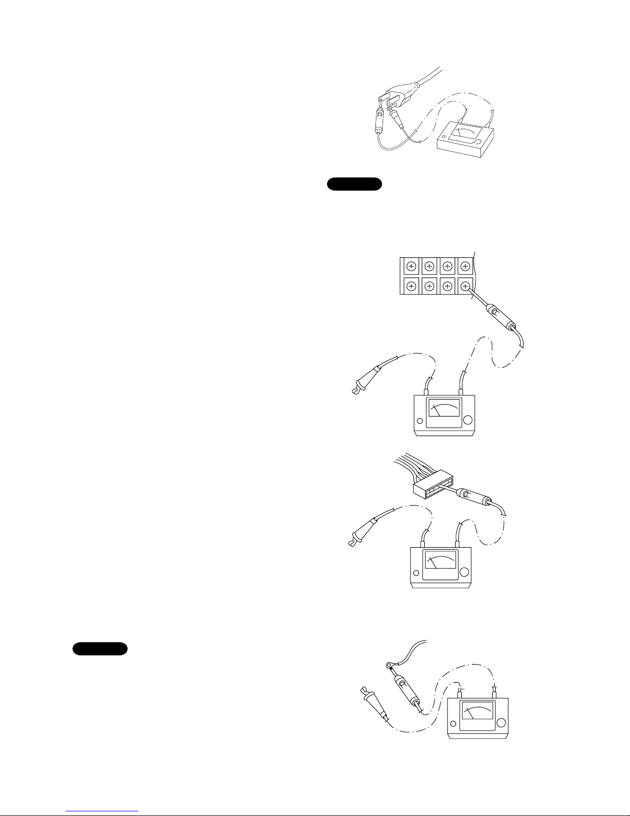
9-1.Measurement of Insulation
Resistance
●
The insulation is in good condition if the resistance
exceeds 2MΩ.
9-1-1.Power Supply Wires
Clamp the grounding terminal of the power plug with a
lead clip of the insulation resistance tester and
measure the resistance by placing a probe on either of
the two power terminals. (Fig. 1)
Then, also measure the resistance between the
grounding and other power terminals. (Fig. 1)
9-1-2.Indoor Unit
Clamp an aluminum plate fin or copper tube with the
lead clip of the insulation resistance tester and
measure the resistance by placing a probe on each
terminal screw where power supply lines are
connected on the terminal plate. (Fig. 2)
9-1-3.Outdoor Unit
Clamp an aluminum plate fin or copper tube with the
lead clip of the insulation resistance tester and
measure the resistance by placing a probe on each
terminal screw on the terminal plate. (Fig. 2)
Note that the ground line terminal should be skipped
for the check.
9-1-4.Measurement of Insulation
Resistance for Electrical Parts
Disconnect the lead wires of the desired electric part
from terminal plate, capacitor, etc. Similarly disconnect
the connector. Then measure the insulation resistance.
(Figs. 3 and 4)
Refer to Electric Wiring Diagram.
If the probe cannot enter the poles because the hole is
too narrow then use a probe with a thinner pin.
NOTE
9.CHECKING ELECTRICAL COMPONENTS
Ground
power plug
(Local supply)
probe
Insulation
tester
Terminal plate
Copper
tube or
metallic part
Clip
Insulation
tester
Probe
Copper
tube or
metallic part
Clip
Insulation
tester
Probe
Clip
Insulation
tester
Probe
Metallic
part
From fan motor,
compressor and
other parts
Fig. 1
Fig. 2
Fig. 3
Fig. 4
The shape of the power plug may differ from
that of the air conditioner which you are
servicing.
NOTE
Page 56
53
9-2.Checking Continuity of Fuse
on PCB Ass'y
●
Remove the PCB Ass’y from the electrical
component box. Then pull out the fuse from the PCB
Ass’y. (Fig. 5)
●
Check for continuity using a multimeter as shown in
Fig. 6.
9-3.Checking Motor Capacitor
Remove the lead wires from the capacitor terminals,
and then place a probe on the capacitor terminals as
shown in Fig. 7. Observe the deflection of the pointer,
setting the resistance measuring range of the
multimeter to the maximum value.
The capacitor is “good” if the pointer bounces to a
great extent and then gradually returns to its original
position.
The range of deflection and deflection time differ
according to the capacity of the capacitor.
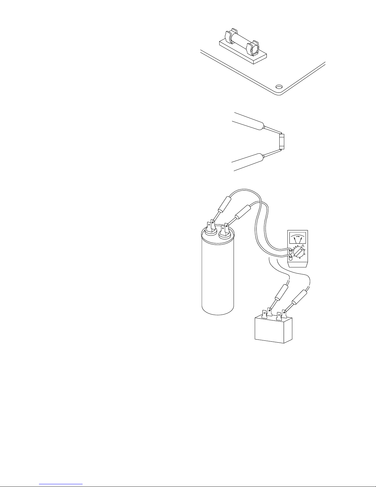
Fuse
PCB Ass’y
Fuse
Compressor motor
capacitor
Fan motor
capacitor
Multimeter
Fig. 5
Fig. 6
Fig. 7
Page 57

54
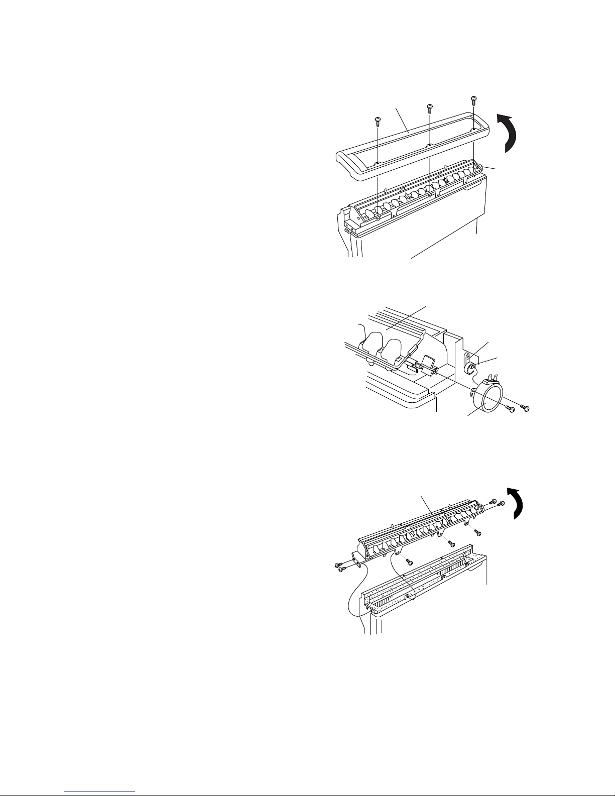
10-1. Removing Air Intake Grille
(1) Hold both ends and pull forward to open the
air intake grille. (Fig. 1)
(2) Remove the metal clips connecting the unit and the
grille. First, with a screwdriver, loosen
the * marked screw a little at the right side clip
(DO NOT loosen it too much, otherwise, the screw
and small metal parts will fall off inside.), then press
on the stopper and pull off. (Fig. 2)
(3) Do the same procedure for the left metal clip.
(4) Unlatch the 2 tabs on the lower part of the grille to
take it off completely.
10. DISASSEMBLY PROCEDURE FOR INDOOR UNIT
IMPORTANT! Please Read Before Starting
Safety precautions for servicing the CEILING-MOUNTED indoor unit
Center latch
Air intake grille
Metal clip
*
Air intake
grille
Unit
For Floor Installation
Fig.1
Fig.2
●
Before attempting to replace heavy and bulky parts such as the evaporator and fan motor, disconnect the
indoor unit from the system and place it on the floor. Refer to the steps given below.
●
When checking or servicing the air intake grille, side panels, or electrical component box, first check that
power is completely disconnected. Pay utmost care that your working platform is stable enough. Also, do not
drop any replaced parts and tools on the floor.
Page 58

55
10-2. Removing Side Panels
(1) Remove the 3 screws attaching the left side panel.
(Fig. 3)
(2) Note the position of the hook on the inside of the
left side panel. To disengage the hook from the slot,
slide down the panel for removal. (Fig. 3)
(3) Do the same procedure for the right side panel.
10-3. Access and Removal of
Electrical Component Box
(1) Remove the front screw with a screwdriver. (Fig. 4)
(2) Slide the lid out and up. (Fig. 4)
(3) Disconnect the wiring as necessary.
(4) Remove the 4 screws, then pull out the electrical
component box. (Fig. 5)
Side panel
Tapping screws
(4 × 10 mm)
Hook
Hook
Slot
Screw
Screw
Electrical component box
Screw
Connectors
Connectors
Hazardous voltage can cause ELECTRIC
SHOCK or DEATH. Disconnect the power
or turn off circuit breaker before you start
checking or servicing.
WARNING
Fig.3
Fig.4
Fig.5
Page 59
56
10-4. Removing Flap Motor
(1) Remove the 3 screws used to mount the top panel.
(Fig. 6)
(2) While unlatching the 2 tabs inside the back of the
top panel, lift the top panel diagonally in the
direction of the arrow.(Fig. 6)
(3) Remove the 2 screws to pull off the flap motor.
The arm and cam come off together with the motor.
(Fig. 7)
10-5. Removing Evaporator
(=Indoor Heat Exchange Coil)
(1) Remove the 7 screws used to mount the blades.
(Fig. 8)
(2) Lift the blades in the direction of the arrow.(Fig. 8)
Top panel
Flap
motor
Screw
Blade
Arm
Cam
Screw
Flap motor
Screw
Blades
Fig.6
Fig.7
Fig.8
Page 60

57
(3) Remove the 6 screws of the front panel and pull it
toward you. (Fig. 9)
(4) Remove the 2 screws used to mount the
evaporator. (Fig. 10)
(5) Remove the rubber cap to pull the thermistor out of
the evaporator. (Fig. 10)
(6) Cut the plastic clamp securing the drain hose to the
front fan casing. (Fig. 10)
(7) The evaporator is built into the drain pan. Pull out
the drain pan together with the evaporator in the
direction of the arrow. (Fig. 10)
The foamed polystyrene drain pan is fragile: DO
NOT apply excessive force when removing it.
(8) The evaporator can be removed by sliding it out
from the drain pan in the direction of the arrow.
(Fig. 11)
Front panel
Screw
Plastic clamp
Drain pan
Screw
Rubber cap
Thermistor
Drain hose
Front
fan casing
Drain pan
Evaporator
(Indoor coil)
Mounting
plate
Mounting
plate
Fig.9
Fig.10
Fig.11
IMPORTANT
Page 61

58
10-6. Removing Fan and Fan Motor
(1) Unlatch the 2 hooks on each side to take off the
front fan casing. (Fig. 12)
(2) Remove the 2 screws attaching the rear fan casing
and then pull the fan casing out.
(3) Insert a hex wrench in the fan boss and turn it
counterclockwise to loosen the centrifugal fan.
The fan can be removed by sliding it to the left.
(Fig. 14)
(4) Remove the 4 bolts to remove the fan motor from
the frame. (Fig. 15)
Hook
Hook
Front fan casing
Rear fan casing
Hex wrench
(3mm or 7/64")
Centrifugal fan
Bolts (M6)
Fan motor
Frame
Fig.12
Fig.13
Fig.14
Fig.15
Page 62

S.A.C. - olgiate olona - printed in italy
R.D. 28 Reyrieux BP 131 - 01601 Trévoux CEDEX France
Tél. 04.74.00.92.92 - Fax 04.74.00.42.00
R.C.S. Bourg-en-Bresse B 759 200 728
 Loading...