

Page 1

Service Manual
5HIULJHUDQW5$
Models:MAFX 96R5I
MAFX126R5I
MAFX186R5I
MAFX246R5I
Remote Controller:
YB1FB7
1. Summary
Indoor Unit:
Page 2

2
Technical Information
Service Manual
Model
Product Code CB435N00400 CB435N00100
Rated Voltage V~ 220-240 220-240
Rated Frequency Hz 50 50
Phases 1 1
Cooling Capacity KW 2.6 3.5
Heating Capacity KW 2.8 3.67
Air Flow Volume (SH/H/M/L) m
3
/h 560/490/430/330 660/540/460/330
Dehumidifying Volume L/h 0.8 1.4
Fan Type Cross-ow Cross-ow
Fan Diameter-height mm Ф98X580 Ф98X633.5
Fan Motor Speed (SH/H/M/L) Cool rpm 1300/1200/1050/800 1350/1200/1050/850
Fan Motor Speed (SH/H/M/L) Heat rpm 1300/1200/1050/900 1300/1150/1000/900
Fan Motor Power Output W 20 20
Fan Motor Running Current A 0.22 0.25
Fan Motor Capacitor μF 1 1.5
Evaporator Material Aluminum Fin-copper Tube Aluminum Fin-copper Tube
Evaporator Pipe Diameter mm Ф5 Ф5
Evaporator Number of Rows 2 2
Evaporator Fin Pitch mm 1.4 1.4
Evaporator Length(L)XHeight(H)
XWidth(W)
mm 584X22.8X266.7 635X22.8X306.3
Motor Model MP24AA MP24BA
Overload Protector / /
Motor Full Load Amp(FLA) A 0.22 0.25
Sound Pressure Level (SH/H/M/L) dB (A) 39/36/32/26 42/39/33/26
Sound Power Level (SH/H/M/L) dB (A) 55/52/44/38 57/53/45/42
Outline Dimension (WXHXD) mm 790X275X200 845X289X209
Package Carton Dimension
(LXWXH)
mm 863X268X352 918X278X364
Package Dimension (LXWXH) mm 866X271X367 921X281X379
Net Weight kg 9 10
Gross Weight kg 11 12
Liquid pipe mm Φ6 Φ6
Gas Pipe(to indoor unit) mm Φ9.52 Φ9.52
Note: The connection pipe applies metric diameter.
2. Specications
2.1 Specication Sheet
The above data is subject to change without notice; please refer to the nameplate of the unit.
MAFX126R5I
MAFX96R5I
Page 3

3
Technical Information
Service Manual
The above data is subject to change without notice; please refer to the nameplate of the unit.
Model
Product Code CB435N00200 CB435N00300
Rated Voltage V~ 220-240 220-240
Rated Frequency Hz 50 50
Phases 1 1
Cooling Capacity KW 5.13 6.7
Heating Capacity KW 5.27 7.25
Air Flow Volume (SH/H/M/L) m
3
/h 800/720/610/520 1150/1000/900/800
Dehumidifying Volume L/h 1.8 2.1
Fan Type Cross-ow Cross-ow
Fan Diameter-height mm Ф106X706 Φ108X830
Fan Motor Speed (SH/H/M/L) Cool rpm 1230/1130/1030/800 1250/1000/900/800
Fan Motor Speed (SH/H/M/L) Heat rpm 1350/1200/1050/900 1250/1000/900/850
Fan Motor Power Output W 35 35
Fan Motor Running Current A 0.35 0.35
Fan Motor Capacitor μF 2.5 3
Evaporator Material Aluminum Fin-copper Tube Aluminum Fin-copper Tube
Evaporator Pipe Diameter mm Ф7 Ф7
Evaporator Number of Rows 2 2
Evaporator Fin Pitch mm 1.4 1.4
Evaporator Length(L)XHeight(H)XWidth(W) mm 715X25.4X304.8 845X25.4X342.9
Motor Model MP35CJ MP35CJ
Overload Protector / /
Motor Full Load Amp(FLA) A 0.35 0.35
Sound Pressure Level (SH/H/M/L) dB (A) 46/42/39/36 48/45/42/39
Sound Power Level (SH/H/M/L) dB (A) 58/54/51/48 64/59/56/53
Outline Dimension (WXHXD) mm 970X300X224 1078X325X246
Package Carton Dimension (LXWXH) mm 1038X380X305 1145X410X335
Package Dimension (LXWXH) mm 1041X383X320 1148X413X350
Net Weight kg 13.5 17
Gross Weight kg 16.5 20.5
Liquid pipe mm Φ6 Φ6
Gas Pipe(to indoor unit) mm Φ12 Φ16
Note: The connection pipe applies metric diameter.
MAFX186R5I
MAFX246R5I
Page 4

4
Technical Information
Service Manual
2.2 Noise Criteria Curve Tables for Both Models
0
10
Noice/dB(A)
20
30
40
50
60
Low Middle High Super High
Indoor Fan Motor Rotating Speed
9K
07K
12K
24K
18K
Page 5

5
Technical Information
Service Manual
W
D
H
09K
12K
18K
24K
90
150
54
168.5 462 159.5
Φ55
Φ55
54
181685104
206
Ф70
685
187
Ф55
Ф55
Ф70
190
181
38
79
154
43
131 542172
43
43
80
143
Ф5 5
Ф5 5
38
43
3. Outline Dimension Diagram
Unit:mm
Model W H D
09K 790 275 200
12K
845 289 209
18K 970 300 224
24K 1078 325 246
Page 6

6
Technical Information
Service Manual
4. Refrigerant System Diagram
outdoor
indoor
D1
C
1
B
1
A
1
filter
A heat exchanger
gas -liquid separator
inverter compressor
discharge silencer
discharge temperature
sensor
SP
4-way valve
outdoor heat exchanger
fan
high pressure switch
B heat exchanger
C heat exchanger
D heat exchanger
filter
filter
filter
filter
C2
C3
D3
D2
B3
B2
A2
A3
A1:A
unit electronic expansion valve B1:B-unit electronic expansion valve
C1:C-unit electronic expansion valve D1:D-unit electronic expansion valve
A2:A-unit gas pipe temperature sensor B2:B-unit gas pipe temperature sensor
C2:C-unit gas pipe temperature sensor D2:D-unit gas pipe temperature sensor
A3:A unit liquid pipe temperature sensor B3:B-unit liquid pipe temperature sensor
C3:C-unit liquid pipe temperature sensor D3:D-unit liquid pipe temperature sensor
Page 7

7
Technical Information
Service Manual
5. Electrical Part
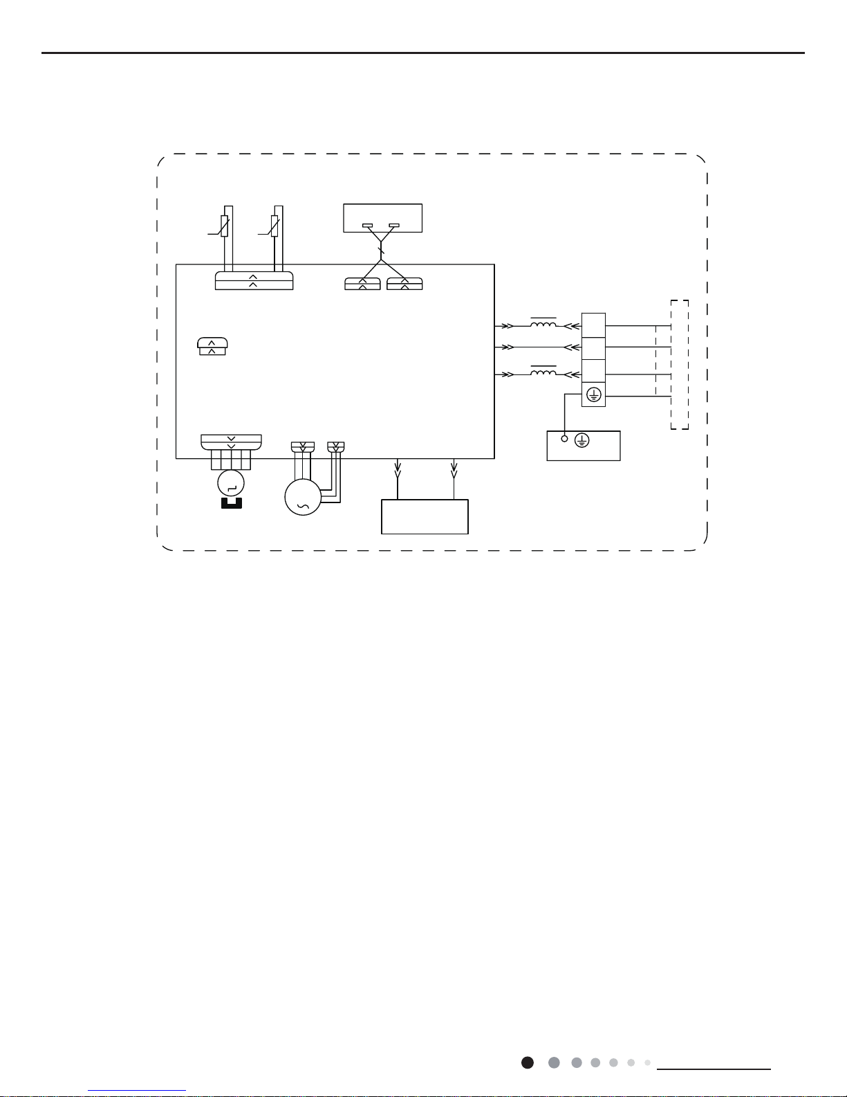
5.1 Wiring Diagram
● Instruction
Symbol Symbol Color Symbol Symbol Color Symbol Name
WH White GN Green CAP Jumper cap
YE Yellow BN Brown COMP Compressor
RD Red BU Blue Grounding wire
YEGN Yellow/Green BK Black / /
VT Violet OG Orange / /
Note: Jumper cap is used to determine fan speed and the swing angle of horizontal lover for this model.
Page 8
8
Technical Information
Service Manual
These circuit diagrams are subject to change without notice, please refer to the one supplied with the unit.
76(1625
7(03
6(1625
7(03
6(1625
57
5220
78%(
67(33,1*
',63/$<
35,17('&,5&8,7%2$5'
5(&(,9(5$1'
',63/$<%2$5'
&$%/(
&211(&7,1*
6:,1*8'
02725
%/2&.
7(50,1$/
$3
-803
&$3
%8
%.
<(*1
(9$325$725
3(
;7
1
0
287'22581,7
$3
3*
*(1(5$725
&2/'3/$60$
)$102725
0
5' %8
+($/7+1
+($/7+/
3*)
',63
',63
%1
<(*1
57
1
&20287
/
%8
%.
%1
/
/
6363222001
● Indoor Unit
MAFX_96-126-186-246_R5I
Page 9

9
Technical Information
Service Manual
5.2 PCB Printed Diagram
● Top view
● Bottom view
1
2
3
45 67 891011
12
13
No. Name
1 Live wire
2 Communication port
3 Fuse
4
Neutral wire for healthy function
(only for the mode with health
function)
5 Neutral wire
6 Needle stand for motor interface
7
Live wire for health function
(only for the model with this
function)
8 Jumper cap
9 Auto button
10
Interface of up&down swing
11 Feedback terminal of motor
12
Needle stand of temperature
sensor
13 Display interface
Page 10

10
Technical Information
Service Manual
6. Function and Control
6.1 Remote Controller Introduction
Introduction for icons on display screen
Introduction for buttons on remote controller
Send signal
Turbo mode
8ć heating function
Set temperature
WiFi(This unit is without WiFi function)
Set time
TIMER ON / TIMER OFF
Child lock
Up & down swing
Set fan speed
Light
Temp. display type
:Set temp.
:Outdoor ambient temp.
:Indoor ambient temp.
Sleep mode
Clock
Heat mode
Fan mode
Dry mode
Cool mode
Auto mode
Operation mode
I feel
Note:
● After putting through the power, the air conditioner will give out a sound. Operation indictor "
" is ON (red indicator). After that,
you can operate the air conditioner by using remote controller.
●
Under ON status, pressing the button on the remote controller, the signal icon " "
on the display of remote controller will blink once
and the air conditioner will give out a “de” sound, which means the signal has been sent to the air conditioner.
● Under OFF status, set temperature and clock icon will be displayed on the display of remote controller (If timer ON, timer OFF and
light functions are set, the corresponding icons will be displayed on the display of remote controller at the same
time); Under ON
status, the display will show the corresponding set function icons.
1.
ON/OFF button
2.
▲ button
3.
▼ button
4.
MODE
5.
FAN button
6.
SWING button
7.
I FEEL button
8.
HEALTH/AIR button
9.
SLEEP button
10.
TEMP button
11.
TIMER ON button
12.
CLOCK button
13.
TIMER OFF button
14.
TURBO button
15.
X-FAN/LIGHT button
Page 11

11
Technical Information
Service Manual
1. ON/OFF button
2. MODE button
3. F
AN button
Press this button can turn on or turn off the air conditioner. After turning on the air conditioner, operation indicator "
"on indoor unit’s
display is ON (green indicator. The colour is different for different models), and indoor unit will give out a sound.
● When selecting auto mode, air conditioner will operate automatically according to factory setting. Set temperature can’t be adjusted and
will not be displayed as well. Press "FAN" button can adjust fan speed. Press "SWING" button can adjust fan blowing angle.
● After selecting cool mode, air conditioner will operate under cool mode. Cool indicator " "on indoor unit is ON. Press "▲" or " ▲ " button
to adjust set temperature. Press "FAN" button to adjust fan speed. Press "SWING" button to adjust fan blowing angle.
● When selecting dry mode, the air conditioner operates at low speed under dry mode. Dry indicator "
" on indoor unit is ON. Under dry
mode, fan speed can’t be adjusted. Press "SWING" button to adjust fan blowing angle.
● When selecting fan mode, the air conditioner will only blow fan, no cooling and no heating. All indicators are OFF. Press "FAN" button to
adjust fan speed. Press "SWING" button to adjust fan blowing angle.
● When selecting heating mode, the air conditioner operates under heat mode. Heat indicator "
" on indoor unit is ON. Press "▲" or " ▲ "
button to adjust set temperature. Press "FAN" button to adjust fan speed. Press "SWING" button to adjust fan blowing angle. (Cooling only
unit won’t receive heating mode signal. If setting heat mode with remote controller, press ON/OFF button can’t start up the unit).
Note:
● For preventing cold air, after starting up heating mode, indoor unit will delay 1~5 minutes to blow air (actual delay time is depend on indoor
ambient temperature).
● Set temperature range from remote controller: 16~30ć (60.8~86.0
O
F); Fan speed: auto, low speed, medium speed, high speed.
5. TURBO button
Under COOL or HEAT mode, press this button to turn to quick COOL or quick HEAT mode. "
" icon is displayed on remote controller.
Press this button again to exit turbo function and "
" icon will disappear.
6. ▲/▲ button
● Press "▲" or "
▲
" button once increase or decrease set temperature 1OC(1OF). Holding "▲" or "▲" button, 2s later, set temperature
on remote controller will change quickly. On releasing button after setting is finished, temperature indicator on indoor unit will change
accordingly. (Temperature can’t be adjusted under auto mode)
● When setting TIMER ON, TIMER OFF or CLOCK, press "▲" or "▲" button to adjust time. (Refer to CLOCK, TIMER ON, TIMER OFF
buttons) When setting TIMER ON, TIMER OFF or CLOCK, press "▲" or "▲" button to adjust time. (Refer to CLOCK, TIMER ON, TIMER
OFF buttons)
Caution:
● Under AUTO speed, air conditioner will select proper fan speed automatically according to factory setting.
● Fan speed under dry mode is low speed.
Pressing this button can set fan speed circularly as: auto (AUTO), low(
) ,medium( ), high( ).
Press this button to select your required operation mode.
AUTO COOL FANDRY HEAT
Auto
4. SWING button
Press this button can select up&down swing angle. Fan blow angle can be selected circularly as below:
● When selecting "
", air conditioner is blowing fan automatically. Horizontal louver will automatically swing up & down at maximum angle.
● When selecting " ǃ ǃ ǃ
ǃ
● When selecting " ǃ
ǃ
● Hold " "button above 2s to set your required swing angle. When reaching your required angle, release the button.
Note:
● " ǃ ǃ " may not be available. When air conditioner receives this signal, the air conditioner will blow fan automatically.
no display
(horizontal louvers stops at current position)
Page 12

12
Technical Information
Service Manual
7. SLEEP button
9. I FEE
L button
10. LIGHT button
1
1. CLOCK button
12. TIMER ON / TIMER OFF button
Under COOL, HEAT or DRY mode, press this button to start up sleep function. "
" icon is displayed on remote controller. Press this button
again to cancel sleep function and "
" icon will disappear.
Press this button to start I FEEL function and "
" will be displayed on the remote controller. After this function is set, the remote controller
will send the detected ambient temperature to the controller and the unit will automatically adjust the indoor temperature according to the
detected temperature. Press this button again to close I FEEL function and "
" will disappear.
● Please put the remote controller near user when this function is set. Do not put the remote controller near the object of high
temperature
or low temperature in order to avoid detecting inaccurate ambient temperature.
Press this button to turn off display light on indoor unit. "
" icon on remote controller disappears. Press this button again to turn on
display light. "
" icon is displayed.
Press this button to set clock time. "
" icon on remote controller will blink. Press "▲" or "▲" button within 5s to set clock time. Each
pressing of "▲" or "
▲
" button, clock time will increase or decrease 1 minute. If hold "▲" or "▲" button, 2s later, time will change quickly.
" icon stops blinking.
Note:
● Clock time adopts 24-hour mode.
● The interval between two operation can’t exceeds 5s. Otherwise, remote controller will quit setting status. Operation for TIMER ON/TIMER
OFF is the same.
● TIMER ON button
"TIMER ON" button can set the time for timer on. After pressing this button, "
" icon disappears and the word "ON" on remote controller
blinks. Press "▲" or "
▲
"button to adjust TIMER ON setting. After each pressing "▲" or "▲" button, TIMER ON setting will increase or
decrease 1min. Hold "▲" or "
▲
" button, 2s later, the time will change quickly until reaching your required time. Press "TIMER ON" to
" icon resumes displaying. Cancel TIMER ON: Under the condition that TIMER ON is
started up, press "TIMER ON" button to cancel it.
● TIMER OFF button
"TIMER OFF" button can set the time for timer off. After pressing this button,"
" icon disappears and the word "OFF" on remote
controller blinks. Press "▲" or "
▲
" button to adjust TIMER OFF setting. After each pressing "▲" or "▲" button,
TIMER OFF setting will increase or decrease 1min. Hold "▲" or "
▲
" button, 2s later, the time will change quickly until reaching your
required time. Press "TIMER OFF" word "OFF" will stop blinking. "
" icon resumes displaying. Cancel TIMER OFF. Under the condition
that TIMER OFF is started up, press "TIMER OFF" button to cancel it.
Note:
● Under on and off status, you can set TIMER OFF or TIMER ON simultaneously.
● Before setting TIMER ON or TIMER OFF, please adjust the clock time.
● After starting up TIMER ON or TIMER OFF, set the constant circulating valid. After that, air conditioner will be turned on or turned off
according to setting time. ON/OFF button has no effect on setting. If you don’t need this function, please use remote controller to cancel it.
8. TEM
P button
By pressing this button, you can see indoor set temperature, indoor ambient temperature or outdoor ambient temperature on indoor unit’s
display. The setting on remote controller is selected circularly as below:
● When selecting "
" or no display with remote controller, temperature indicator on indoor unit displays set temperature.
● When selecting "
" with remote controller, temperature indicator on indoor unit displays indoor ambient temperature.
● When selecting "
" with remote controller, temperature indicator on indoor unit displays outdoor ambient temperature.
Note:
●
Outdoor temperature display is not available for some models. At that time, indoor
unit receives " "signal, while it displays indoor set
temperature.
● It’s defaulted to display set temperature when turning on the unit.There is no display in the remote controller.
● Only for the models whose indoor unit has dual-8 display.
● When selecting displaying of indoor or outdoor ambient temperature, indoor temperature indicator displays corresponding temperature and
no display
Page 13

13
Technical Information
Service Manual
Function introduction for combination buttons
Operation guide
Replacement of batteries in remote controller
1. Energy-saving function
1.
After putting through the power, press "ON/OFF" button on remote controller to turn on the air conditioner.
2. Press "MODE" button to select your required mode: AUTO, COOL, DRY, FAN, HEAT.
3. Press "▲" or "
▲
" button to set your required temperature. (Temperature can’t be adjusted under auto mode).
4. Press "FAN" button to set your required fan speed: auto, low, medium and high speed.
5. Press "SWING" button to select fan blowing angle.
● During operation, point the remote control signal sender at the receiving window on indoor unit.
●
The distance between signal sender and receiving window should be no more than 8m, and there should be no obstacles between them.
indoor unit during operation.
● Replace new batteries of the same model when replacement is required.
● When you don’t use remote controller for a long time, please take out the batteries.
● If the display on remote controller is fuzzy or there’s no display, please replace batteries.
2. 8
ć
heating function
3. Child lock function
4. T
emperature display switchover function
5. About WIFI function(This unit is without WiFi function)
Under cooling mode, press "TEMP" and " CLOCK" buttons simultaneously to start up or turn off energy-saving function. When energy-saving
function is started up, "SE" will be shown on remote controller, and air conditioner will adjust the set temperature automatically according
to factory setting to reach to the best energy-saving effect. Press "TEMP" and "CLOCK"buttons simultaneously again to exit energy-saving
function.
Note:
● Under energy-saving function, fan speed is defaulted at auto speed and it can’t be adjusted.
●
Under energy-saving function, set temperature can’t be adjusted. Press "TURBO"
button and the remote controller won’t send signal.
● Sleep function and energy-saving function can’t operate at the same time. If energy-saving function has been set under cooling mode,
press sleep button will cancel energy-saving function. If sleep function has been set under cooling mode, start up the energy-saving
function will cancel sleep function.
Under heating mode, press "TEMP" and "CLOCK" buttons simultaneously to start
up or turn off 8ć heating function. When this function is
started up, "
" and "8ć" will be shown on remote controller, and the air conditioner keep the heating status
at 8ć. Press "TEMP" and
"CLOCK" buttons simultaneously again to exit 8ćheating function.
Note:
● Under 8ć heating function, fan speed is defaulted at auto speed and it can’t be adjusted.
● Under 8ć heating function, set temperature can’t be adjusted. Press
"
TURBO" button and the remote controller won’t send signal.
● Sleep function and 8ć heating function can’t operate at the same time. If 8ćheating function has been set under cooling mode, press
sleep button will cancel 8ć heating function. If sleep function has been set under cooling mode, start up the 8ć heating function will
cancel sleep function.
● Under temperature display, the remote controller will display 46 heating.
Press "▲" and "
▲
" simultaneously to turn on or turn off child lock function. When child lock function is on, " " icon is displayed on remote
controller. If you operate the remote controller, the "
" icon will blink three times without sending signal to the unit.
Under OFF status, press "
▲
" and "MODE" buttons simultaneously to switch temperature display between ć and .
Press "MODE" and "TURBO" button simultaneously to turn on or turn off WIFI function. When WIFI function is turned on, the " WIFI " i
con
will be displayed on remote controller; Long press "MODE" and "TURBO" buttons simultaneously for 10s, remote controller will send WIFI
reset code and then the WIFI function will be turned on. WIFI function is defaulted ON after energization of the remote controller.
1. Press the back side of remote controller marked with "
out
the cover of battery box along the arrow direction.
2. Replace two 7# (AAA 1.5V) dry batteries, and make sure the position of "+" polar and "-" polar
are correct.
3. Reinstall the cover of battery box.
Note:
signal sender battery
Cover of battery box
remove
reinstall
Page 14

14
Technical Information
Service Manual
6.2 Brief Description of Modes and Functions
1.Basic function of system
(1)Cooling mode
(1) Under this mode, fan and swing operates at setting status. Temperature setting range is 16~30OC.
(2) During malfunction of outdoor unit or the unit is stopped because of protection, indoor unit keeps original operation status.
(2)Drying mode
(1) Under this mode, fan operates at low speed and swing operates at setting status. Temperature setting range is 16~30OC.
(2) During malfunction of outdoor unit or the unit is stopped because of protection, indoor unit keeps original operation status.
(3) Protection status is same as that under cooling mode.
(4) Sleep function is not available for drying mode.
(3)Heating mode
(1) Under this mode, Temperature setting range is 16~30OC.
(2) Working condition and process for heating mode:
When turn on the unit under heating mode, indoor unit enters into cold air prevention status. When the unit is stopped or at OFF status,
and indoor unit has been started up just now, the unit enters into residual heat-blowing status.
(4)Working method for AUTO mode:
1.Working condition and process for AUTO mode:
a.Under AUTO mode, standard heating Tpreset=20OC and standard cooling Tpreset=25OC. The unit will switch mode automatically
according to ambient temperature.
2.Protection function
a. During cooling operation, protection function is same as that under cooling mode.
b. During heating operation, protection function is same as that under heating mode.
3. Display: Set temperature is the set value under each condition. Ambient temperature is (Tamb.-Tcompensation) for heat pump unit
and Tamb. for cooling only unit.
4. If there’s I feel function, Tcompensation is 0. Others are same as above.
(5)Fan mode
Under this mode, indoor fan operates at set fan speed. Compressor, outdoor fan, 4-way valve and electric heating tube stop operation.
Indoor fan can select to operate at high, medium, low or auto fan speed. Temperature setting range is 16~30
O
C.
2. Other control
(1) Buzzer
Upon energization or availably operating the unit or remote controller, the buzzer will give out a beep.
(2) Auto button
If press this auto button when turning off the unit, the complete unit will operate at auto mode. Indoor fan operates at auto fan speed
and swing function is turned on. Press this auto button at ON status to turn off the unit.
(3) Auto fan
Heating mode: During auto heating mode or normal heating ode, auto fan speed will adjust the fan speed automatically according to
ambient temperature and set temperature.
(4) Sleep
After setting sleep function for a period of time, system will adjust set temperature automatically.
(5) Timer function:
General timer and clock timer functions are compatible by equipping remote controller with different functions.
(6) Memory function
memorize compensation temperature, off-peak energization value.
Memory content: mode, up&down swing, light, set temperature, set fan speed, general timer (clock timer can’t be memorized).
After power recovery, the unit will be turned on automatically according to memory content.
(7) Health function
During operation of indoor fan, set health function by remote controller. Turn off the unit will also turn off health function.
Turn on the unit by pressing auto button, and the health is defaulted ON.
Page 15

15
Technical Information
Service Manual
(8)I feel control mode
After controller received I feel control signal and ambient temperature sent by remote controller, controller will work according to the ambient
temperature sent by remote controller.
(9)Compulsory defrosting function
(1) Start up compulsory defrosting function
Under ON status, set heating mode with remote controller and adjust the temperature to 16OC. Press “+, -, +, -, +,-” button successively
within 5s and the complete unit will enter into compulsory defrosting status. Meanwhile, heating indicator on indoor unit will ON 10s and OFF
0.5s successively. (Note: If complete unit has malfunction or stops operation due to protection, compulsory defrosting function can be started
up after malfunction or protection is resumed.
(2)Exit compulsory defrosting mode
After compulsory defrosting is started up, the complete unit will exit defrosting operation according to the actual defrosting result, and the
complete unit will resume normal heating operation.
(10)Refrigerant recovery function (applicable for moving the unit or maintaining the unit)
(1) Start up refrigerant recovery function
Set cooling mode with remote controller within 5min after energization, adjust temperature at 16OC and press light button on remote
controller for 3 times successively to any one indoor unit within 3s and then the complete unit will enter into refrigerant recovery status. All
indoor units display Fo. Maintenance person close all liquid valves. After 5min, withstand the thimble of all checking valves with tools one by
one. If there’s no refrigerant spraying out, close corresponding valve immediately, turn off the unit with remote controller and then remove the
connection pipe.
(2) Exit refrigerant recovery function
During refrigerant recovery process, if any one indoor unit receives any remote control signal or refrigerant recovery function has operates
for about 25min, refrigerant recovery function will be exited automatically. If the complete unit is at standby status before refrigerant recovery,
the complete unit will still at standby status after refrigerant recovery. If the complete unit is at ON status, the unit will operate according to
original operation mode.
(11)Ambient temperature display control mode
1. When user set the remote controller to display set temperature (corresponding remote control code: 01), current set temperature will be
displayed.
2. Only when remote control signal is switched to indoor ambient temperature display status (corresponding remote control code: 10) from
other display status (corresponding remote control code: 00, 01,11),controller will display indoor ambient temperature for 3s and then turn
back to display set temperature.
Under this mode, indoor fan operates at set fan speed. Compressor, outdoor fan, 4-way valve and electric heating tube stop operation.
Indoor fan can select to operate at high, medium, low or auto fan speed. Temperature setting range is 16~30
O
C.
(12)Off-peak energization function
Adjust compressor’s minimum stop time. The original minimum stop time is 180s and then we change to:
The time interval between two start-ups of compressor can’t be less than 180+T s(0≤T≤15). T is the variable of controller. That’s to say
the minimum stop time of compressor is 180s~195s. Read-in T into memory chip when refurbish the memory chip each time. After power
recovery, compressor can only be started up after 180+T s at least.
(13) SE control mode
The unit operates at SE status.
(14) X-fan mode
When X-fan function is turned on, after turn off the unit, indoor fan will still operate at low speed for 2min and then the complete unit will be
turned off. When x-fan function is turned off, after turn off the unit, the complete unit will be turned off directly.
(15) 8º heating function
Under heating mode, you can set 8º heating function by remote controller. The system will operate at 8ºset temperature.
(16)Turbo function
Turbo function can be set under cooling and heating modes. Press Fan Speed button to cancel turbo setting. Turbo function is not available
under auto, drying and fan modes.
(17)Mode shock
When there’s indoor unit under operation, if start up other indoor unit and the setting mode is inconsistent with that indoor unit, mode shock
will occur. The indoor with mode shock displays “E7” and indoor fan stops operation. Corresponding relationship for mode shock and
operation status after shock is as below:
Page 16

16
Technical Information
Service Manual
Mode relationship table for mode shock:
Mode Indoor unit with
mode shock
Operation status after mode shock
Indoor unit A Indoor unit B Indoor unit A Indoor unit B
Cooling/drying heating Indoor unit B Cooling/drying Indoor fan stops operation
Heating Cooling, drying, fan Indoor unit B Heating Indoor fan stops operation
Fan Heating Indoor unit A Indoor fan stops operation Heating
Note: (1) Indoor unit A: The indoor unit under operation currently
(2) Indoor unit B: The indoor unit is tuned on latter
(3) If set auto mode with remote controller, the complete unit will judge according to actual operation mode under auto mode.
Page 17

17
Installation and Maintenance
Service Manual
1. Select the installation location according to the requirement of this manual.(See the requirements in installation
part)
2. Handle unit transportation with care; the unit should not
be carried by only one person if it is more than 20kg.
3. When installing the indoor unit and outdoor unit, a sufcient xing bolt must be installed; make sure the installation
support is rm.
4. Ware safety belt if the height of working is above 2m.
5. Use equipped components or appointed components during installation.
6. Make sure no foreign objects are left in the unit after nishing installation.
Electrical Safety Precautions:
7. Notes for Installation and Maintenance
Safety Precautions:
Important!
Please read the safety precautions carefully before
installation and maintenance.
The following contents are very important for installation
and maintenance.
Please follow the instructions below.
●The installation or maintenance must accord with the
instructions.
●Comply with all national electrical codes and local
electrical codes.
●Pay attention to the warnings and cautions in this
manual.
●All installation and maintenance shall be performed by
distributor or qualied person.
●All electric work must be performed by a licensed
technician according to local regulations and the
instructions given in this manual.
●Be caution during installation and maintenance. Prohibit
incorrect operation to prevent electric shock, casualty and
other accidents.
1. Cut off the power supply of air conditioner before
checking and maintenance.
2. The air condition must apply specialized circuit and
prohibit share the same circuit with other appliances.
3. The air conditioner should be installed in suitable
location and ensure the power plug is touchable.
4. Make sure each wiring terminal is connected firmly
during installation and maintenance.
5. Have the unit adequately grounded. The grounding
wire can’t be used for other purposes.
6. Must apply protective accessories such as protective
boards, cable-cross loop and wire clip.
7. The live wire, neutral wire and grounding wire of
power supply must be corresponding to the live wire,
neutral wire and grounding wire of the air conditioner.
8. The power cord and power connection wires can’t be
pressed by hard objects.
9. If power cord or connection wire is broken, it must be
replaced by a qualied person.
1. Avoid contact between refrigerant and re as it generates
poisonous gas; Prohibit prolong the connection pipe by
welding.
2. Apply specied refrigerant only. Never have it mixed with
any other refrigerant. Never have air remain in the refrigerant
line as it may lead to rupture or other hazards.
3. Make sure no refrigerant gas is leaking out when
installation is completed.
4. If there is refrigerant leakage, please take sufficient
measure to minimize the density of refrigerant.
5. Never touch the refrigerant piping or compressor without
wearing glove to avoid scald or frostbite.
Warnings
Refrigerant Safety Precautions:
Improper installation may lead to re hazard, explosion,
electric shock or injury.
Installation Safety Precautions:
Part
Ⅱ
: Installation and Maintenance
10. If the power cord or connection wire is not long enough,
please get the specialized power cord or connection wire
from the manufacture or distributor. Prohibit prolong the wire
by yourself.
11. For the air conditioner without plug, an air switch must
be installed in the circuit. The air switch should be all-pole
parting and the contact parting distance should be more than
3mm.
12. Make sure all wires and pipes are connected properly and
the valves are opened before energizing.
13. Check if there is electric leakage on the unit body. If yes,
please eliminate the electric leakage.
14. Replace the fuse with a new one of the same specication
if it is burnt down; don’t replace it with a cooper wire or
conducting wire.
15. If the unit is to be installed in a humid place, the circuit
breaker must be installed.
Page 18

18
Installation and Maintenance
Service Manual
Main Tools for Installation and Maintenance
1. Level meter, measuring tape
4. Electroprobe
7. Electronic leakage detector
10. Pipe pliers, pipe cutter
2. Screw driver
5. Universal meter
8. Vacuum pump
11. Pipe expander, pipe bender
3. Impact drill, drill head, electric drill
6. Torque wrench, open-end wrench, inner
hexagon spanner
9. Pressure meter
12. Soldering appliance, refrigerant container
Page 19

19
Installation and Maintenance
Service Manual
8. Installation
8.1 Installation Dimension Diagram
Drainagepipe
At least250cm
At least 15cm
At leas
t 3
00cm
Spacetothe
Spacetothe ceiling
Space t
o t
he obstruction
At least15cm
At least 15cm
Spacetothe wall
Space to the wall
Page 20

20
Installation and Maintenance
Service Manual
Preparation before installation
Prepare tools
Read the requirements
for electric connection
select installation
location
Select indoor unit
installation location
Install wall-mounting
frame, drill wall holes
Connect pipes of indoor
unit and drainage pipe
Connect wires of indoor unit
Connect wires of outdoor unit
Bind up pipes and
hang the indoor unit
Make the bound pipes pass
through the wall hole and then
connect outdoor unit
Neaten the pipes
Vacuum pumping and leakage detection
Check after installation and test operation
Finish installation
Note: this flow is only for reference; please find the more detailed installation steps in this section
.
Select outdoor unit
installation location
Install the support of outdoor unit
(select it according to the actual situation)
Install drainage joint of outdoor unit
(only for cooling and heating unit)
Connect pipes of outdoor unit
Start installation
Fix outdoor unit
Installation procedures
Page 21

21
Installation and Maintenance
Service Manual
No. Name No. Name
1 Indoor unit 8 Sealing gum
2 Outdoor unit 9 Wrapping tape
3 Connection pipe 10
Support of outdoor
unit
4 Drainage pipe 11 Fixing screw
5
Wall-mounting
frame
12
Drainage plug(cooling
and heating unit)
6
Connecting
cable(power cord)
13
Owner’s manual,
remote controller
7 Wall pipe
1. Safety Precaution
(1) Must follow the electric safety regulations when installing
the unit.
(2) According to the local safety regulations, use qualified
power supply circuit and air switch.
(3) Make sure the power supply matches with the requirement
of air conditioner. Unstable power supply or incorrect wiring
may result in electric shock,re hazard or malfunction. Please
install proper power supply cables before using the air
conditioner.
(4) Properly connect the live wire, neutral wire and grounding
wire of power socket.
(5) Be sure to cut off the power supply before proceeding any
work related to electricity and safety.
(6) Do not put through the power before nishing installation.
(7) For appliances with type Y attachment,the instructions
shall contain the substance of thefollowing.If the supply cord is
damaged,it must be replaced by the manufacturer,its service
agent or similarly qualied persons in order to avoid a hazard.
(8) The temperature of refrigerant circuit will be high, please
keep the interconnection cable away from the copper tube.
(9) The appliance shall be installed in accordance with national
wiring regulations.
8.2 Installation Parts-checking
8.3 Selection of Installation Location
8.4 Electric Connection Requirement
8.5 Installation of Indoor Unit
1.Please contact the local agent for installation.
2.Don't use unqualied power cord.
1. Basic Requirement:
Installing the unit in the following places may cause
malfunction. If it is unavoidable, please consult the local dealer:
(1) The place with strong heat sources, vapors, ammable or
explosive gas, or volatile objects spread in the air.
(2) The place with high-frequency devices (such as welding
machine, medical equipment).
(3) The place near coast area.
(4) The place with oil or fumes in the air.
(5) The place with sulfureted gas.
(6) Other places with special circumstances.
(7) The appliance shall nost be installed in the laundry.
2. Grounding Requirement:
(1) The air conditioner is rst class electric appliance. It must
be properly grounding with specialized grounding device
by a professional. Please make sure it is always grounded
effectively, otherwise it may cause electric shock.
(2) The yellow-green wire in air conditioner is grounding wire,
which can't be used for other purposes.
(3) The grounding resistance should comply with national
electric safety regulations.
(4) The appliance must be positioned so that the plug is
accessible.
(5) An all-pole disconnection switch having a contact separation
of at least 3mm in all poles should be connected in xed wiring.
(6) Including an air switch with suitable capacity, please note
the following table. Air switch should be included magnet
buckle and heating buckle function, it can protect the circuitshort and overload. (Caution: please do not use the fuse only
for protect the circuit)
1. Choosing Installation Iocation
Recommend the installation location to the client and then
conrm it with the client.
2. Install Wall-mounting Frame
(1) Hang the wall-mounting frame on the wall; adjust it in
horizontal position with the level meter and then point out the
screw xing holes on the wall.
(2) Drill the screw xing holes on the wall with impact drill (the
specification of drill head should be the same as the plastic
expansion particle) and then ll the plastic expansion particles
2. Indoor Unit:
(1) There should be no obstruction near air inlet and air outlet.
(2) Select a location where the condensation water can be
dispersed easily andwon't affect other people.
(3) Select a location which is convenient to connect the
outdoor unit and near the power socket.
(4) Select a location which is out of reach for children.
(5)
The location should be able to withstand
the weight of
indoor unit and won't increase noise and vibration.
(6)
The appliance must be installed 2.5m above oor.
(7) Don't install the indoor unit right above the electric
appliance.
(8) Please try your best to keep way from uorescent lamp.
Note:
in the holes.
(3) Fix the wall-mounting frame on the wall with tapping screws
(ST4.2X25TA) and then check if the frame is rmly installed by
pulling the frame. If the plastic expansion particle is loose,
please drill another xing hole nearby.
Page 22

22
Installation and Maintenance
Service Manual
Left
Rear left
Right
Rear right
Cut off
the hole
Left Right
5-10
°
Φ55/70mm
Indoor
Outdoor
(1) Pay attention to dust prevention and take relevant safety
measures when opening the hole.
(2) The plastic expansion particles are not provided and should
be bought locally.
Fig.1
Fig.2
Fig.3
Fig.4
3. Install Wall-mounting Frame
(1) Choose the position of piping hole according to the direction
of outlet pipe. The position of piping hole should be a little
lower than the wall-mounted frame.(As show in Fig.1)
4. Outlet Pipe
(1) The pipe can be led out in the direction of right, rear right,
left or rear left.(As show in Fig.3)
(2) When selecting leading out the pipe from left or right, please
cut off the corresponding hole on the bottom case.(As show in
Fig.4)
(2) Open a piping hole with the diameter of Φ55/70mm on the
selected outlet pipe position.In order to drain smoothly, slant
the piping hole on the wall slightly downward to the outdoor
side with the gradient of 5-10°.(As show in Fig.2)
Note:
Insulating pipe
Torque wrench
Open-end
wrench
Indoor pipe
Pipe
Union nut
Union nutPipe joint
Pipe
Hex nut diameter(mm) Tightening torque(N m)
Φ6 15~20
Φ9.52 30~40
Φ12 45~55
Φ16 60~65
Φ19 70~75
Refer to the following table for wrench moment of force
:
Fig.5 Fig.6
Fig.7
5. Connect the Pipe of Indoor Unit
(1) Aim the pipe joint at the corresponding bellmouth.(As show
in Fig.5)
(2) Pretightening the union nut with hand.
(3) Adjust the torque force by referring to the following sheet.
Place the open-end wrench on the pipe joint and place the
torque wrench on the union nut. Tighten the union nut with
torque wrench.(As show in Fig.6)
(4) Wrap the indoor pipe and joint of connection pipe with
insulating pipe, and then wrap it with tape.(As show in Fig.7)
6. Install Drain Hose
(1) Connect the drain hose to the outlet pipe of indoor unit.(As
show in Fig.8)
(2) Bind the joint with tape.(As show in Fig.9)
Left
Wall
Φ55mm
Right
Mark in the middle of it
Level meter
Rear piping hole
Wall
Space
to the
wall
above
150mm
Space
to the
wall
above
150mm
Φ55mm
Rear piping hole
Left
Wall
Φ55/70mm
Right
Mark in the middle of it
Level meter
Rear piping hole
Wall
Space
to the
wall
above
150mm
Space
to the
wall
above
150mm
Φ55/70mm
Rear piping hole
Left
Wall
Φ55
Right
Mark in the middle of it
Level meter
Rear piping hole
Wall
Space
to the
wall
above
150mm
Space
to the
wall
above
150mm
Φ55
Rear piping hole
.
Outlet pipe
Drain hos
e
Drain hose
Tape
Outlet pipe
Drain hose
Insulating pipe
(1) Add insulating pipe in the indoor drain hose in order to
prevent condensation.
(2) The plastic expansion particles are not provided.
(As show in Fig.10)
Fig.8
Fig.9
Fig.10
Note:
Page 23

23
Installation and Maintenance
Service Manual
(4) Put wiring cover back and then tighten the screw.
(5) Close the panel.
Indoor unit
Gas
pipe
Indoor and
outdoor power cord
Liquid
pipe
Drain hose
Band
Drain hose
Band
Connection pipe
Indoor power cord
Power connection
wire
Cable-cross
hole
(2) If the length of power connection wire is insufcient, please
contact the supplier for a new one. Avoid extending the wire by
yourself.
(3) For the air conditioner with plug, the plug should be
reachable after nishing installation.
(4) For the air conditioner without plug, an air switch must be
installed in the line. The air switch should be all-pole parting
and the contact parting distance should be more than 3mm.
(1) All wires of indoor unit and outdoor unit should be
connected by a professional.
(1) The power cord and control wire can't be crossed or
winding.
(2) The drain hose should be bound at the bottom.
7. Connect Wire of Indoor Unit
(1) Open the panel, remove the screw on the wiring cover and
then take down the cover.(As show in Fig.11)
8. Bind up Pipe
(1) Bind up the connection pipe, power cord and drain hose
with the band.(As show in Fig.14)
(2) Reserve a certain length of drain hose and power cord
for installation when binding them. When binding to a certain
degree, separate the indoor power and then separate the drain
hose.(As show in Fig.15)
(3) Bind them evenly.
(4) The liquid pipe and gas pipe should be bound separately at
the end.
(2) Make the power connection wire go through the cable-cross
hole at the back of indoor unit and then pull it out from the front
side.(As show in Fig.12)
(3) Remove the wire clip; connect the power connection wire
to the wiring terminal according to the color; tighten the screw
and then x the power connection wire with wire clip.(As show
in Fig.13)
Note:
Note:
Fig.11
Fig.12
Fig.13
Fig.14
Fig.15
wiring cover
screw
panel
N(1) 23
blue brownblack
yellowgreen
Outdoor unit connection
9. Hang the Indoor Unit
(1) Put the bound pipes in the wall pipe and then make them
pass through the wall hole.
(2) Hang the indoor unit on the wall-mounting frame.
(3) Stuff the gap between pipes and wall hole with sealing gum.
(4) Fix the wall pipe.(As show in Fig.16)
(5) Check if the indoor unit is installed rmly and closed to the
wall.(As show in Fig.17)
Do not bend the drain hose too excessively in order to prevent
blocking.
Note:
Indoor
Outdoor
Wall pipe
Sealing gum
Upper hook
Lower hook of
wall-mounting frame
Fig.16
Fig.17
Page 24

24
Installation and Maintenance
Service Manual
NO. Items to be checked Possible malfunction
1 Has the unit been installed rmly? The unit may drop, shake or emit noise.
2
Have you done the refrigerant leakage
test?
It may cause insufcient cooling (heating) capacity.
3 Is heat insulation of pipeline sufcient? It may cause condensation and water dripping.
4 Is water drained well? It may cause condensation and water dripping.
5
Is the voltage of power supply according
to the voltage marked on the nameplate?
It may cause malfunction or damage the parts.
6
Is electric wiring and pipeline installed
correctly?
It may cause malfunction or damage the parts.
7 Is the unit grounded securely? It may cause electric leakage.
8
Does the power cord follow the
specication?
It may cause malfunction or damage the parts.
9
Is there any obstruction in air inlet and air
outlet?
It may cause insufcient cooling (heating).
10
The dust and sundries caused during
installation are removed?
It may cause malfunction or damaging the parts.
11
The gas valve and liquid valve of
connection pipe are open completely?
It may cause insufcient cooling (heating) capacity.
1. Check after Installation
Check according to the following requirement after nishing installation.
8.8 Check after Installation and Test
Operation
2. Test Operation
(1) Preparation of test operation
● The client approves the air conditioner installation.
● Specify the important notes for air conditioner to the client.
(2) Method of test operation
● Put through the power, press ON/OFF button on the remote controller to start operation.
● Press MODE button to select AUTO, COOL, DRY, FAN and HEAT to check whether the operation is normal or not.
● If the ambient temperature is lower than 16℃, the air conditioner can’t start cooling.
Page 25

25
Installation and Maintenance
Service Manual
9. Maintenance
9.1 Error Code
1. Malfunction display requirement
When there are several malfunctions, they will be displayed circularly.
2. Malfunction display method
(1) Hardware malfunction: immediate display; refer to “error code list”;
(2) Operation state: immediate display; refer to “error code list”;
(3) Other malfunctions: it is displayed after the compressor stops for 200s; refer to “error code list”.
Note: when the compressor is restarted, the malfunction display delay time (200s) is cleared.
3. Malfunction display control
The indicator lamp and dual 8 nixie tube displays shall be synchronized. That is when the indicator lamp blinks, the dual 8 nixie
tube displays the corresponding malfunction code.
4. Display control viaremote controller
Enter display control: press light button successively for 4 times within 3s to display the corresponding malfunction code;
Exit display control: pressing light button successively for 4 times within 3s or after display is shown for 5min, the display will
terminate.
Error Code List
Malfunction Name Malfunction types
Dual-8
Nixie Tube
Indicator Display
Operation
indicator
Cooling
indicator
Heating
indicator
Fault in input power zero Hardware malfunction U8 blink 17 times
Jumper cap malfunction protection Hardware malfunction C5 blink 15 times
No feedback of indoor fan motor
Hardware malfunction
H6 blink 11 times
Indoor ambient sensor open or short circuit Hardware malfunction F1 blink once
Indoor tube sensor open or short circuit Hardware malfunction F2 blink twice
Inlet tube sensor malfunction Hardware malfunction b5 blink 19 times
Outlet tube sensor malfunction Hardware malfunction b7 blink 22 times
IPM sensor circuit malfunction Hardware malfunction P7 blink 18 times
Outdoor ambient sensor open or short circuit Hardware malfunction F3 blink 3 times
Inlet pipe temperature sensor of outdoor
condenser is open-circuit/short circuit(commercial
air con)
Hardware malfunction A5
Outdoor tube sensor open or short circuit Hardware malfunction F4 blink 4 times
outlet pipe temperature sensor of outdoor
condenser is open-circuit/short circuit(commercial
air con)
Hardware malfunction A7
Exhaust sensor open or short circuit Hardware malfunction F5 blink 5 times
Communication failure between indoor unit and
outdoor unit
Hardware malfunction E6 blink 6 times
Compressor phase current detection circuit
malfunction
Hardware malfunction U1 blink 12 times
Compressor demagnetization protection It can be displayed
through remote
controller within 200s
and displayed directly
after 200s
HE blink 14 times
PN voltage drop protection U3 blink 20 times
IPM high temperature protection P8 blink 19 times
Refrigerant-lacking or blockage protection F0 blink 10 times
Capacitor charge malfunction Hardware malfunction PU blink 17 times
Refrigerant system high pressure protection Hardware malfunction E1 blink once
system low-pressure protection (reserved) Hardware malfunction E3 blink 3 times
Compressor over load protection
It can be displayed
through remote
controller within 200s
and displayed directly
after 200s
H3 blink 3 times
Fault in matching Hardware malfunction LP blink 19 times
Loading EEPROM malfunction Hardware malfunction EE blink 15 times
AC current detect circuit malfunction Hardware malfunction U5 blink 13 times
Outdoor DC fan motor malfunction Hardware malfunction L3 blink 23 times
Mode conict operation status E7 blink 7 times
Page 26

26
Installation and Maintenance
Service Manual
Note: Please refer to service manual for the troubleshooting procedure for outdoor unit.
Recovery refrigerant mode operation status Fo blink once blink once
Startup failure
It can be displayed
through remote
controller within 200s
and displayed directly
after 200s
Lc blink 11 times
Compressor exhaust high temperature protection E4 blink 4 times
Anti-high temperature protection E8 blink 8 times
AC over-current protection E5 blink 5 times
Over compressor phase current protection P5 blink 15 times
Compressor loss step protection H7 blink 7 times
Compressor loss of phase protection Ld
IPM protection H5 blink 5 times
Low PN voltage protection PL blink 21 times
Over voltage protection for PN PH blink 11 times
PFC protection HC blink 6 times
4-way valve reversal abnormal U7 blink 20 times
Page 27

27
Installation and Maintenance
Service Manual
1. Malfunction of Temperature Sensor F1, F2
Main detection points:
● Is the wiring terminal between the temperature sensor and the controller loosened or poorly contacted?
● Is there short circuit due to trip-over of the parts?
● Is the temperature sensor broken?
● Is mainboard broken?
Malfunction diagnosis process:
Is the wiring terminal between the
temperature sensor and the controller
loosened or poorly contacted?
Start
Insert the temperature
sensor tightly
Yes
Yes
Yes
Yes
Yes
Yes
No
No
No
No
No
No
Is malfunction
eliminated
Is malfunction
eliminated
Is malfunction
eliminated
Replace it with a
temperature sensor with
the same model
Make the parts upright
Is there short circuit due to trip-
over of the parts
Is the temperature sensor normal
according to the resistance table?
Replace the mainboard with
the same model.
End
Page 28
28
Installation and Maintenance
Service Manual
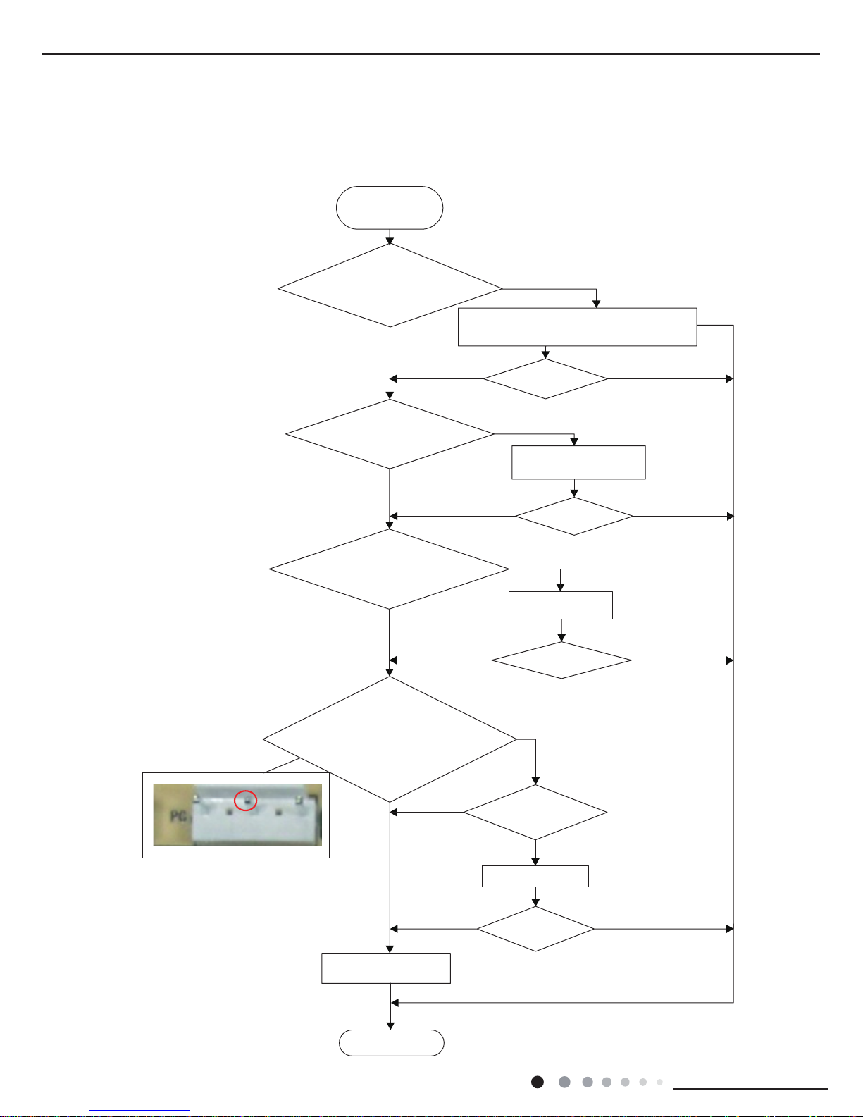
2. Malfunction of Blocked Protection of IDU Fan Motor H6
Main detection points:
● SmoothlyIs the control terminal of PG motor connected tightly?
● SmoothlyIs the feedback interface of PG motor connected tightly?
● The fan motor can't operate?
● The motor is broken?
● Detectioncircuit of the mainboard is dened abnormal?
Malfunction diagnosis process:
Start
While power is off stir the blade
with a tool to see whether the
blade rotates smoothly
Check if the connection of PG
motor feedback terminal is rm
Check if the connection of PG
motor control terminal is rm
Turn on the unit again; measure
whether the output voltage on
control terminal for PG motor is
more than 50V within 1 min after
the louvers are opened
Tighten the screw; reassemble the blade, motor
and shaft bearing rubber base sub-assy to make
sure there is no foreign object between them
Yes
Yes
Yes
Yes
Yes
Yes
Yes
Yes
Yes
Yes
No
No
No
No
No
No
No
No
No
Is malfunction
eliminated
Is malfunction
eliminated
Is malfunction
eliminated
Is malfunction
eliminated
Is the motor started up
Replace PG motor
Replace the mainboard
with the same model
Measure the voltage of this foot to
neutral wire on the mainboard
End
Reinstall the blade
and motor correctly
Insert the control terminal
of PG motor tightly
Page 29

29
Installation and Maintenance
Service Manual
3. Malfunction of Protection of Jumper Cap C5
Main detection points:
● Is there jumper cap on the mainboard?
● Is the jumper cap inserted correctly and tightly?
● The jumper is broken?
● The motor is broken?
● Detection circuit of the mainboard is dened abnormal?
Malfunction diagnosis process:
Start
Is there jumper cap on the mainboard?
Is the jumper cap inserted correctly
and tightly?
Replace the jumper cap with
the same model
Appearance of the
jumper cap
Assemble the jumper
cap with the same model
Insert the jumper
cap tightly
Is malfunction
eliminated
Is malfunction
eliminated
Is malfunction
eliminated
Replace the mainboard
with the same model
End
Yes
Yes
Yes
Yes
Yes
No
No
No
No
No
Page 30

30
Installation and Maintenance
Service Manual
4. Malfunction of Zero-crossing Inspection Circuit Malfunction of the IDU Fan Motor U8
Main detection points:
● Instant energization afte de-energization while the capacitordischarges slowly?
● The zero-cross detectioncircuit of the mainboard is dened abnormal?
Malfunction diagnosis process:
Turn power off for
1minute,the turn
back on
The unit returns to normal.
Conclusion:U8 is displayed due to
power off/on while the
capacitor discharges slowly.
U8 is still
displayed
The zero-cross detection circuit
of the mainboard is dened
abnormal.Replace the mainboard
with the same model
Yes
No
Start
End
Page 31

31
Installation and Maintenance
Service Manual
5. Malfunction of Overcurrent Protection E5
Main detection points:
● Is the supply voltage unstable with big uctuation?
● Is the supply voltage too low with overload?
● Hardware trouble?
Malfunction diagnosis process:
Start
Is the supply voltage unstable
with big uctuation?
Normal uctuation should be within 10 %
of the rated voltage on the nameplate
Adjust the supply voltage to maintain it
within normal range
Clean the indoor and outdoor heat
exchangers and remove the blockage
of air inlet and outlet
Check the motor and reinstall the
motor to have the fan run normally
Replace the mainboard with the same
model
Flush the heat exchangers with high
pressure nitrogen
Replace the compressor
Replace the mainboard
with the same model
End
Is the supply voltage too low
with overload?
Is the indoor / outdoor
heat exchanger dirty,or are the air inlet
and outlet blocked?
The fan is abnormal? Fan
speed is too low or fan doesn’t rotate
Measure the current of live wire on
the main board with a clamp ampere
meter. Is the current higher than the
value of the overcurrent protection?
Is there blockage inside the system?
(Filth blockage, ice plug, greasy
blockage, the cut off valve hasn’t been
opened completely)
Is the compressor running abnormally?
Is there abnormal sound or oil leakage;
Is the temperature of the shell too high,
etc.?
Is malfunction
eliminated
Is malfunction
eliminated
Is malfunction
eliminated
Is malfunction
eliminated
Is malfunction
eliminated
Is malfunction
eliminated
Is malfunction
eliminated
Yes Yes
Yes
Yes
Yes
Yes
Yes
Yes
Yes
Yes
Yes
Yes
Yes
Yes
No No
No
No
No
No
No No
No
No
No
No
No
Page 32

32
Installation and Maintenance
Service Manual
6. High temperature and overload protection (AP1 below means control board of outdoor unit) E8
Main detection points:
● If the outdoor ambient temperature is in normal range;
● If the indoor and outdoor fan are running normally;
● If the radiating environment of indoor and outdoor unit is good.
Malfunction diagnosis process:
Start
If the outdoor ambient temperature is
higher than 53°C?
If the airow of indoor and outdoor unit
is good?
If the indoor and outdoor fan are
running normally?
Replace outdoor
mainboard
Connect normally?
Adjust the
connection
Replace fan
capacitor
Replace motor
Fan capacitor is broken?
Motor is broken?
Replace mainboard
Improve the radiating environment of
unit (clean the heat exchanger and
remove surrounding obstacles)
Normal protection, please use it
after improving the outdoor ambient
temperature
Unit restarts
normally
Unit restarts
normally
End
Yes
Yes
Yes
Yes
Yes
Yes
Yes
Yes
No
No
No
No
No
No
Page 33

33
Installation and Maintenance
Service Manual
7.
Overload Protection Compressor
H3
Main detection points:
● Heat exchange of unit is not good? (heat exchanger is dirty and unit radiating environment is bad)
● Fan motor is not working?
● Too much load of the system causes high temperature of compressor after working for a long time?
● Whether high pressure switch is normal?
● If the refrigerant is leaked?
Malfunction diagnosis process:
Start
Outdoor and indoor heat
exchangers are too dirty or the air
inlet/outlet is blocked.
Clean the outdoor and indoor heat exchangers
and remove blockage of air inlet/outlet.
Malfunction is
eliminated.
Malfunction is
eliminated.
Malfunction is
eliminated.
Malfunction is
eliminated.
Malfunction is
eliminated.
Malfunction is
eliminated.
Check motor and re-install the motor to
make it run normally.
Make compressor run normally.
Remove blockage in the system.
Replace high pressure switch
Check the leaking status of refrigerant
and charge refrigerant
Fan motor is not working.
Abnormal fan speed; fan speed is too
low or the fan doesn't run.
Compressor doesn't work
normally. Strange noise or leakage occurs.
Temperature of the shell is too high.
System is blocked inside
(dirt block, ice block, oil block, Y-valve not
fully open).
Check whether high
pressure switch is normal
Check whether the
refrigerant is leaking and cause
overheating protection to compressor
Replace a main
board of the
same model.
End
Yes
Yes
Yes
Yes
Yes
Yes
Yes
Yes
Yes
Yes
Yes
Yes
No
No
No
No
No
No
No
No
No
No
No
No
Page 34

34
Installation and Maintenance
Service Manual
9.2 Maintenance Method for Normal Malfunction
Possible Causes Discriminating Method (Air conditioner Status) Troubleshooting
Set temperature is improper Observe the set temperature on remote controller Adjust the set temperature
Rotation speed of the IDU fan
motor is set too low
Small wind blow Set the fan speed at high or medium
Filter of indoor unit is blocked Check the lter to see it's blocked Clean the lter
Installation position for indoor unit
and outdoor unit is improper
Check whether the installation postion is proper
according to installation requirement for air
conditioner
Adjust the installation position, and install the
rainproof and sunproof for outdoor unit
Refrigerant is leaking
Discharged air temperature during cooling is
higher than normal discharged wind temperature;
Discharged air temperature during heating is
lower than normal discharged wind temperature;
Unit's pressure is much lower than regulated
range
Find out the leakage causes and deal with it.
Add refrigerant.
Malfunction of 4-way valve Blow cold wind during heating Replace the 4-way valve
Malfunction of capillary
Discharged air temperature during cooling is
higher than normal discharged wind temperature;
Discharged air temperature during heating is
lower than normal discharged wind temperature;
Unit't pressure is much lower than regulated
range. If refrigerant isn’t leaking, part of capillary
is blocked
Replace the capillary
Flow volume of valve is
insufcient
The pressure of valves is much lower than that
stated in the specication
Open the valve completely
Malfunction of horizontal louver Horizontal louver can’t swing
Refer to point 3 of maintenance method for
details
Malfunction of the IDU fan motor The IDU fan motor can’t operate
Refer to troubleshooting for H6 for maintenance
method in details
Malfunction of the ODU fan motor The ODU fan motor can't operate
Refer to point 4 of maintenance method for
details
Malfunction of compressor Compressor can't operate
Refer to point 5 of maintenance method for
details
1. Air Conditioner Can't be Started Up
2. Poor Cooling (Heating) for Air Conditioner
3. Horizontal Louver Can't Swing
Possible Causes Discriminating Method (Air conditioner Status) Troubleshooting
No power supply, or poor
connection for power plug
After energization, operation indicator isn’t bright
and the buzzer can't give out sound
Conrm whether it's due to power failure. If yes,
wait for power recovery. If not, check power
supply circuit and make sure the power plug is
connected well.
Wrong wire connection between
indoor unit and outdoor unit,
or poor connection for wiring
terminals
Under normal power supply circumstances,
operation indicator isn't bright after energization
Check the circuit according to circuit diagram
and connect wires correctly. Make sure all
wiring terminals are connected rmly
Electric leakage for air conditioner
After energization, room circuit breaker trips off at
once
Make sure the air conditioner is grounded
reliably
Make sure wires of air conditioner is connected
correctly
Check the wiring inside air conditioner. Check
whether the insulation layer of power cord is
damaged; if yes, place the power cord.
Model selection for air switch is
improper
After energization, air switch trips off Select proper air switch
Malfunction of remote controller
After energization, operation indicator is bright,
while no display on remote controller or buttons
have no action.
Replace batteries for remote controller
Repair or replace remote controller
Possible Causes Discriminating Method (Air conditioner Status) Troubleshooting
Wrong wire connection, or poor
connection
Check the wiring status according to circuit
diagram
Connect wires according to wiring diagram to
make sure all wiring terminals are connected
rmly
Stepping motor is damaged Stepping motor can't operate Repair or replace stepping motor
Main board is damaged
Others are all normal, while horizontal louver
can't operate
Replace the main board with the same model
Page 35

35
Installation and Maintenance
Service Manual
7. Abnormal Sound and Vibration
Possible causes Discriminating method (air conditioner status) Troubleshooting
When turn on or turn off the unit,
the panel and other parts will
expand and there's abnormal
sound
There's the sound of "PAPA"
Normal phenomenon. Abnormal sound will
disappear after a few minutes.
When turn on or turn off the unit,
there's abnormal sound due
to ow of refrigerant inside air
conditioner
Water-running sound can be heard
Normal phenomenon. Abnormal sound will
disappear after a few minutes.
Foreign objects inside the indoor
unit or there're parts touching
together inside the indoor unit
There's abnormal sound fro indoor unit
Remove foreign objects. Adjust all parts'
position of indoor unit, tighten screws and stick
damping plaster between connected parts
Foreign objects inside the outdoor
unit or there're parts touching
together inside the outdoor unit
There's abnormal sound fro outdoor unit
Remove foreign objects. Adjust all parts'
position of outdoor unit, tighten screws and
stick damping plaster between connected parts
Short circuit inside the magnetic
coil
During heating, the way valve has abnormal
electromagnetic sound
Replace magnetic coil
Abnormal shake of compressor Outdoor unit gives out abnormal sound
Adjust the support foot mat of compressor,
tighten the bolts
Abnormal sound inside the
compressor
Abnormal sound inside the compressor
If add too much refrigerant during maintenance,
please reduce refrigerant properly. Replace
compressor for other circumstances.
6. Air Conditioner is Leaking
Possible causes Discriminating method (air conditioner status) Troubleshooting
Drain pipe is blocked Water leaking from indoor unit
Eliminate the foreign objects inside the drain
pipe
Drain pipe is broken Water leaking from drain pipe Replace drain pipe
Wrapping is not tight
Water leaking from the pipe connection place of
indoor unit
Wrap it again and bundle it tightly
5. Compressor Can't Operate
Possible causes Discriminating method (air conditioner status) Troubleshooting
Wrong wire connection, or poor
connection
Check the wiring status according to circuit
diagram
Connect wires according to wiring diagram to
make sure all wiring terminals are connected
rmly
Capacity of compressor is
damaged
Measure the capacity of fan capacitor with an
universal meter and nd that the capacity is out of
the deviation range indicated on the nameplate of
fan capacitor.
Replace the compressor capacitor
Power voltage is a little low or
high
Use universal meter to measure the power supply
voltage. The voltage is a little high or low
Suggest to equip with voltage regulator
Coil of compressor is burnt out
Use universal meter to measure the resistance
between compressor terminals and it's 0
Repair or replace compressor
Cylinder of compressor is blocked Compressor can't operate Repair or replace compressor
4. ODU Fan Motor Can't Operate
Possible causes Discriminating method (air conditioner status) Troubleshooting
Wrong wire connection, or poor
connection
Check the wiring status according to circuit
diagram
Connect wires according to wiring diagram to
make sure all wiring terminals are connected
rmly
Capacity of the ODU fan motor is
damaged
Measure the capacity of fan capacitor with an
universal meter and nd that the capacity is out of
the deviation range indicated on the nameplate of
fan capacitor.
Replace the capacity of fan
Power voltage is a little low or
high
Use universal meter to measure the power supply
voltage. The voltage is a little high or low
Suggest to equip with voltage regulator
Motor of outdoor unit is damaged
When unit is on, cooling/heating performance
is bad and ODU compressor generates a lot of
noise and heat.
Change compressor oil and refrigerant. If no
better, replace the compressor with a new one
Page 36

36
Installation and Maintenance
Service Manual
10. Exploded View and Parts List
09/12K
B4 P
a
nel
B6/A5
Panel
The component picture is only for reference; please refer to the actual product.
Page 37

37
Installation and Maintenance
Service Manual
Above data is subject to change without notice.
No.
Description
Part Code
Qty
Product Code CB435N00400 CB435N00100
1
Front Panel Assy 20000300050 20000300049 1
2
Display Board 30565281 30565281 1
3
Front Case Assy 00000200040 00000200045 1
4
Helicoid Tongue 26112508 26112436 1
5
Left Axile Bush 10512037 10512037 1
6
Rear Case assy 20162010 00000100093 1
7
Drainage Hose 0523001408 05230014 1
8
Ring of Bearing 26152022 26152022 1
9
O-Gasket sub-assy of Bearing 7651205102 7651205102 1
10
Evaporator Support 24212180 24212179 1
11
Cold Plasma Generator 1114001602 1114001602 1
12
Evaporator Assy 01002000044 01100100245 1
13
Wall Mounting Frame 01252043 01252484 1
14
Cross Flow Fan 10352059 10352056 1
15
Fan Motor 150120874 1501214603 1
16
Connecting pipe clamp 2611216401 2611216401 1
17
Rubber Plug (Water Tray) 76712012 76712012 1
18
Stepping Motor 1521212901 1521210701 1
19
Crank 73012005 73012005 1
20
Electric Box Assy 10000202398 10000202284 1
21 Axile Bush 10542036 10542036 1
22 Terminal Board 42011233 42011233 1
23 Jumper 4202300104 4202300114 1
24
Main Board 30138000427 30138000430 1
25
Electric Box Cover Sub-Assy 01402065 01402065 1
26
Shield Cover of Electric Box Cover 01592150 01592150 1
27
Electric Box Cover2 20112208 20112208 1
28
Connecting Cable 4002052317 4002052317 0
29
Remote Controller 30510474 30510474 1
MAFX126R5I
MAFX96R5I
Page 38

38
Installation and Maintenance
Service Manual
Above data is subject to change without notice.
No.
Description
Part Code
Qty
Product Code
1
Front Panel Assy
2
Display Board
3
Front Case Assy
4
Helicoid Tongue
5
Left Axile Bush
6
Rear Case assy
7
Drainage Hose
8
Ring of Bearing
9
O-Gasket sub-assy of Bearing
10
Evaporator Support
11
Cold Plasma Generator
12
Evaporator Assy
13
Wall Mounting Frame
14
Cross Flow Fan
15
Fan Motor
16
Connecting pipe clamp
17
Rubber Plug (Water Tray)
18
Stepping Motor
19
Crank
20
Electric Box Assy
21 Axile Bush
22 Terminal Board
23 Jumper
24
Main Board
25
Electric Box Cover Sub-Assy
26
Shield Cover of Electric Box Cover
27
Electric Box Cover2
28
Connecting Cable
29
Remote Controller
Page 39

39
Installation and Maintenance
Service Manual
18K
The component picture is only for reference; please refer to the actual product.
Page 40

40
Installation and Maintenance
Service Manual
Above data is subject to change without notice.
No.
Description
Part Code
Qty
Product Code CB435N00200
1
Decorative Strip / /
2
Front Panel 20000300040 1
3
Display Board 30565278 1
4
Filter Sub-Assy 11122089 2
5
Decorative Board (Left) / /
6
Front Case 2002248401 1
7
Guide Louver 1051276501 1
8
Axile Bush 10542036 2
9
Air Louver 10512732 3
10
Helicoid tongue 26112512 1
11
Left Axile Bush 10512037 1
12
Rear Case assy 22202571 1
13
Rubber Plug (Water Tray) 76712012 1
14
O-Gasket sub-assy of Bearing 7651205102 1
15 Ring of Bearing 26152025 1
16
Evaporator Support
24212177 1
17
Evaporator Assy 01002000014 1
18
Cross Flow Fan 10352060 1
19
Fan Motor 1501214502 1
20
Motor Press Plate 26112511 1
21 Wall Mounting Frame 01362026 1
22 Connecting Pipe Clamp 2611218801 1
23 Crank 73012005 1
24
Stepping Motor 1521240212 1
25
Drainage hose 05230014 1
26
Electric Box Assy 10000202378 1
27
Lower Shield of Electric Box 01592139 1
28
Electric Box 20112211 1
29
Jumper 4202300121 1
30
Main Board 30138000429 1
31
Shield Cover of Electric Box 01592140 1
32
Electric Box Cover 20112209 1
33
Terminal Board 42011233 1
34
Decorative Board (Right) / /
35
Screw Cover 2425201726 3
36
Electric Box Cover2 20112210 1
37
Connecting Cable 4002052317 0
38
Remote Controller 30510474 1
39
Cold Plasma Generator 1114001602 1
MAFX186R5I
Page 41

41
Installation and Maintenance
Service Manual
24K
The component picture is only for reference; please refer to the actual product.
Page 42

42
Installation and Maintenance
Service Manual
Above data is subject to change without notice.
No.
Description
Part Code
Qty
Product Code CB435N00300
1
Front Panel Assy 20000300048 1
2
Filter Sub-Assy 11012007 2
3
Screw Cover 2425245301 3
4
Front Case Assy 00000200043 1
5
Air Louver(Manual) 10512737 3
6
Helicoid Tongue 26112513 1
7
Left Axile Bush 10512037 1
8
Rear Case assy 22202570 1
9
Rubber Plug (Water Tray) 76712012 1
10
Ring of Bearing 26152025 1
11
O-Gasket of Cross Fan Bearing 76512203 1
12
Cross Flow Fan 10352057 1
13
Evaporator Support 24212178 1
14
Evaporator Assy 01002988 1
15 Cold Plasma Generator 1114001602 1
16
Wall Mounting Frame 01252229 1
17
Motor Press Plate 26112515 1
18
Fan Motor 15012145 1
19
Connecting pipe clamp 26112514 1
20
Drainage Hose 0523001405 1
21 Stepping Motor 1521240212 1
22 Crank 73012005 1
23 Guide Louver 1051232001 1
24
Axile Bush 10542036 2
25
Electric Box 20112211 1
26
Terminal Board 42011233 1
27
Electric Box Cover2 20112210 1
28
Main Board 30138000426 1
29
Display Board 30565278 1
30
Shield cover of Electric Box 01592140 1
31
Electric Box Cover 20112209 1
32
Jumper 4202300125 1
33
Lower Shield of Electric Box 01592139 1
34
Electric Box Assy 10000202379 1
35
Power Cord / /
36
Connecting Cable 4002052317 0
37
Temperature Sensor 3900031302 1
38
Remote Controller 30510474 1
MAFX246R5I
Page 43

43
Installation and Maintenance
Service Manual
11. Removal Procedure
Caution: discharge the refrigerant
completely before removal.
a
b
Axile bush
Push out the axile bush on horizontal
louver. Bend the horizontal louver with
hand and then separate the horizontal
louver from the crankshaft of step motor
to remove it.
Horizontal louver
Location of step motor
ProcedureStep
1.Remove lter assy
2. Remove horizontal louver
Front panel
Front
case
Right lter
Groove
Left lter
Open the front panel. Push the left and
right filters to make them break away
from the groove on the front case. Then
remove the left and right filters one by
one.
Screw off the 2 screws that are locking
the display board. Separate the display
board from the front panel.
Separate the panel rotation shaft from
the groove xing the front panel and then
removes the front panel.
Panel
Screws
Display
Front panel
Panel rotation
Groove
3. Remove panel
09/12K
Page 44

44
Installation and Maintenance
Service Manual
a
b
ProcedureStep
Remove the screws on the electric box
cover 2 to remove the electric box cover 2.
Remove the screws xing front case.
Note:
1.Open the screw caps before removing
the screws around the air outlet.
2.The quantity of screws fixing the front
case sub-assy is different for different
models.
Loosen the connection clasps between
vertical louver and bottom case to remove
vertical louver.
Loosen the connection clasps between
front case sub-assy and bottom case. Lift
up the front case sub-assy and take it out.
Electric box cover 2
Screw
4. Remove electric box cover 2
5. Remove front case sub-assy
6. Remove vertical louver
Front case
sub-assy
Front case
sub-assy
Clasp
Screw caps
Screws
bottom case
Screw
Vertical
louver
Vertical
louver
Clasps
Bottom
case
Page 45

45
Installation and Maintenance
Service Manual
a
b
c
d
Procedure
Step
Loosen the connection clasps between
shield cover of electric box sub-assy and
electric box, and then remove the shield
cover of electric box sub-assy.
Remove the screw xing electric box assy .
①
Remove the cold plasma generator by
screwing off one locking screw on the
generator.
②
Take off the indoor tube temperature
sensor.
③
Screw off one grounding screw.
④
Remove the wiring terminals of motor and
stepping motor.
⑤
Remove the electric box assy.
Twist off the screws that are locking lead
wire and rotate the electric box assy.
Twist off the screws that are locking wire
clip.
Loosen the power cord and remove its wiring
terminal. Lift up the main board and take it
off.
Remove the display board by taking out its
wiring terminal.
Remove temperature sensor by taking out
its wiring terminal.
7. Remove electric box assy
Electric box
Electric box assy
Clasps
Shield cover of electric
box sub-assy
Cold plasma
generator
Grounding
screw
Screw
Power cord
Screw
Wiring terminal
of display board
Wiring terminal of
temperature sensor
Wire clip
Screw
Main board
Main board
Screw
Screw
Indoor tube
temperature
sensor
Wiring
terminal
of motor
Wiring
terminal
of stepping
motor
Page 46

46
Installation and Maintenance
Service Manual
a
c
d
b
First remove the left side of evaporator from
the groove of bottom shell and then remove
the right side from the clasp on the bottom
shell.
Instruction: Some wiring terminal of this
product is with lock catch and other devices.
The pulling method is as below:
1.Remove the soft sheath for some terminals
at rst, hold the circlip and then pull out the
terminals.
2.Pull out the holder for some terminals at
rst (holder is not available for some wiring
terminal), hold the connector and then pull the
terminal.
Circlip
Soft sheath
Holder
Connector
ProcedureStep
Remove 3 screws xing evaporator assy.
8. Remove evaporator assy
Screws
Connection pipe clamp
Evaporator assy
Evaporator assy
Screw
Groove
Bottom shell
Clasp
Connection pipe
At the back of the unit, remove the
screw fixing connection pipe clamp
and then remove the connection pipe
clamp.
Adjust the position of connection pipe
on evaporator slightly and then lift the
evaporator upwards to remove it.
Page 47

47
Installation and Maintenance
Service Manual
ProcedureStep
Remove the screws fixing motor clamp
and then remove the motor clamp.
Remove the screws at the connection
place of cross flow blade and motor; lift
the motor and cross flow blade upwards
to remove them.
Remove the bearing holder sub-assy.
Remove the screw xing step motor and
then remove the step motor.
Screws
Screw
Motor clamp
9. Remove motor and cross ow blade
Motor
Cross ow
Holder
sub-assy
Step motor
Screws
a
b
Page 48

48
Installation and Maintenance
Service Manual
18/24K
1. Remo ve filter assy
Open the front panel. Push the left and right
filters to make them break away from the
groove on the front case. Then remove the left
and right filters one by one.
Groove
Screw off the 2 screws that are locking the
display board. Separate the displayboard from
the front panel.
Right filter
Front
case
Left filter
Front panel
Page 49

49
Installation and Maintenance
Service Manual
Loosen the connection clasps between front
case sub-assy and bottom case. Lift up the
front case sub-assy and take it out.
Swingmotor
Screw off the screws that are locking theswing
motor and take the motor off.
2
2.
2
Page 50

50
Installation and Maintenance
Service Manual
Indoor tube
temperature sensor
Main
board
Wiring
terminal
of mo tor
Wiring
terminal
of stepping
motor
Screw
Grounding
screw
Wire binder
Cut off the wire binder and pull out the
indoor tube temperature sensor.
Screw off one grounding screw.
Remove the wiring terminals of motor and
stepping motor.
Remove the electric box assy.
Screw off the screws that are locking each
lead wire.
Screw
Wire clip
Power cord
Rotate the electric box assy. Twist offthe screws
that are locking the wire clip and loosen the
power cord. Remove the wiring terminal of
power cord. Lift up the main board and take it off.
Page 51

51
Installation and Maintenance
Service Manual
Rear ca se assy
First remove the left side of evaporator from
the groove on the rear case assy. Then
remove the right side from the clasp on the
rear case assy.
Groove
Clasp
Page 52

52
Installation and Maintenance
Service Manual
Page 53

53
Installation and Maintenance
Service Manual
Appendix:
1.Standard length of connection pipe
● 5m, 7.5m, 8m.
2.Min. length of connection pipe is 3m.
3.Max. length of connection pipe and max. high difference.
4.The additional refrigerant oil and refrigerant charging required after
prolonging connection pipe
● After the length of connection pipe is prolonged for 10m at the basis
of standard length, you should add 5ml of refrigerant oil for each
additional 5m of connection pipe.
● The calculation method of additional refrigerant charging amount (on
the basis of liquid pipe):
Appendix 1: Reference Sheet of Celsius and Fahrenheit
Appendix 2: Conguration of Connection Pipe
Cooling capacity
Max length of
connection pipe
Max height
difference
9000 Btu/h(2637 W) 15 m 10 m
12000 Btu/h(3516 W) 20 m 10 m
18000 Btu/h(5274 W) 25 m 10 m
24000 Btu/h(7032 W) 25 m 10 m
Set temperature
Conversion formula for Fahrenheit degree and Celsius degree: Tf=Tcx1.8+32
Ambient temperature
Fahrenheit
display
temperature
(℉)
Fahrenheit
(℉)
Celsius
(℃)
Fahrenheit
display
temperature
(℉)
Fahrenheit
(℉)
Celsius
(℃)
Fahrenheit
display
temperature
(℉)
Fahrenheit
(℉)
Celsius
(℃)
32/33 32 0 55/56 55.4 13 79/80 78.8 26
34/35 33.8 1 57/58 57.2 14 81 80.6 27
36 35.6 2 59/60 59 15 82/83 82.4 28
37/38 37.4 3 61/62 60.8 16 84/85 84.2 29
39/40 39.2 4 63 62.6 17 86/87 86 30
41/42 41 5 64/65 64.4 18 88/89 87.8 31
43/44 42.8 6 66/67 66.2 19 90 89.6 32
45 44.6 7 68/69 68 20 91/92 91.4 33
46/47 46.4 8 70/71 69.8 21 93/94 93.2 34
48/49 48.2 9 72 71.6 22 95/96 95 35
50/51 50 10 73/74 73.4 23 97/98 96.8 36
52/53 51.8 11 75/76 75.2 24 99 98.6 37
54 53.6 12 77/78 77 25
Fahrenheit
display
temperature
(℉)
Fahrenheit
(℉)
Celsius
(℃)
Fahrenheit
display
temperature
(℉)
Fahrenheit
(℉)
Celsius
(℃)
Fahrenheit
display
temperature
(℉)
Fahrenheit
(℉)
Celsius
(℃)
61 60.8 16 69/70 69.8 21 78/79 78.8 26
62/63 62.6 17 71/72 71.6 22 80/81 80.6 27
64/65 64.4 18 73/74 73.4 23 82/83 82.4 28
66/67 66.2 19 75/76 75.2 24 84/85 84.2 29
68 68 20 77 77 25 86 86 30
Additional refrigerant charging amount for R22, R407C, R410A and R134a
Diameter of connection pipe Outdoor unit throttle
Liquid pipe(mm) Gas pipe(mm) Cooling only(g/m) Cooling and heating(g/m)
Ф6 Ф9.5 or Ф12 15 20
Ф6 or Ф9.5 Ф16 or Ф19 15 20
Ф12 Ф19 or Ф22.2 30 120
Ф16 Ф25.4 or Ф31.8 60 120
Ф19 / 250 250
Ф22.2 / 350 350
● When the length of connection pipe is above 5m, add refrigerant according to the prolonged length of liquid pipe. The additional
refrigerant charging amount per meter is different according to the diameter of liquid pipe. See the following sheet.
● Additional refrigerant charging amount = prolonged length of liquid pipe X additional refrigerant charging amount per meter
Page 54

54
Installation and Maintenance
Service Manual
F:Inspection
● Check the quality of expanding port. If there is any blemish, expand the
port again according to the steps above.
The length is equal
Improper expanding
leaning
damaged
surface
crack uneven
thicknes
s
Smooth surface
Downwards
Pipe
Shaper
Union pipe
Pipe
Expander
Hard
mold
Pipe
Pipe
Pipe cutter
Leaning Uneven Burr
Improper pipe expanding is the main cause of refrigerant leakage.Please
expand the pipe according to the following steps:
A:Cut the pip
● Conrm the pipe length according to the distance of indoor unit and outdoor unit.
● Cut the required pipe with pipe cutter.
B:Remove the burrs
● Remove the burrs with shaper and prevent the burrs from getting into the pipe.
C:Put on suitable insulating pipe
D:Put on the union nut
● Remove the union nut on the indoor connection pipe and outdoor valve; install
the union nut on the pipe.
E:Expand the port
● Expand the port with expander.
● "A" is different according to the diameter, please refer to the sheet below:
Outer diameter(mm)
A(mm)
Max Min
Ф6 - 6.35 (1/4") 1.3 0.7
Ф9.52 (3/8”) 1.6 1.0
Ф12 - 12.70 (1/2”) 1.8 1.0
Ф16 - 15.88 (5/8”) 2.4 2.2
Appendix 3: Pipe Expanding Method
Note:
Note:
Page 55

55
Installation and Maintenance
Service Manual
Temp(oC) Resistance(kΩ) Temp(oC) Resistance(kΩ) Temp(oC) Resistance(kΩ) Temp(oC) Resistance(kΩ)
-19 138.1 20 18.75 59 3.848 98 1.071
-18 128.6 21 17.93 60 3.711 99 1.039
-17 121.6 22 17.14 61 3.579 100 1.009
-16 115 23 16.39 62 3.454 101 0.98
-15 108.7 24 15.68 63 3.333 102 0.952
-14 102.9 25 15 64 3.217 103 0.925
-13 97.4 26 14.36 65 3.105 104 0.898
-12 92.22 27 13.74 66 2.998 105 0.873
-11 87.35 28 13.16 67 2.896 106 0.848
-10 82.75 29 12.6 68 2.797 107 0.825
-9 78.43 30 12.07 69 2.702 108 0.802
-8 74.35 31 11.57 70 2.611 109 0.779
-7 70.5 32 11.09 71 2.523 110 0.758
-6 66.88 33 10.63 72 2.439 111 0.737
-5 63.46 34 10.2 73 2.358 112 0.717
-4 60.23 35 9.779 74 2.28 113 0.697
-3 57.18 36 9.382 75 2.206 11 4 0.678
-2 54.31 37 9.003 76 2.133 11 5 0.66
-1 51.59 38 8.642 77 2.064 11 6 0.642
0 49.02 39 8.297 78 1.997 11 7 0.625
1 46.6 40 7.967 79 1.933 118 0.608
2 44.31 41 7.653 80 1.871 11 9 0.592
3 42.14 42 7.352 81 1.811 120 0.577
4 40.09 43 7.065 82 1.754 121 0.561
5 38.15 44 6.791 83 1.699 122 0.547
6 36.32 45 6.529 84 1.645 123 0.532
7 34.58 46 6.278 85 1.594 124 0.519
8 32.94 47 6.038 86 1.544 125 0.505
9 31.38 48 5.809 87 1.497 126 0.492
10 29.9 49 5.589 88 1.451 127 0.48
11 28.51 50 5.379 89 1.408 128 0.467
12 27.18 51 5.197 90 1.363 129 0.456
13 25.92 52 4.986 91 1.322 130 0.444
14 24.73 53 4.802 92 1.282 131 0.433
15 23.6 54 4.625 93 1.244 132 0.422
16 22.53 55 4.456 94 1.207 133 0.412
17 21.51 56 4.294 95 1.171 134 0.401
18 20.54 57 4.139 96 1.136 135 0.391
19 19.63 58 3.99 97 1.103 136 0.382
Appendix 4: List of Resistance for Temperature Sensor
Resistance Table of Ambient Temperature Sensor for Indoor and Outdoor Units(15K)
Page 56

56
Installation and Maintenance
Service Manual
Temp(oC) Resistance(kΩ) Temp(oC) Resistance(kΩ) Temp(oC) Resistance(kΩ) Temp(oC) Resistance(kΩ)
-19 181.4 20 25.01 59 5.13 98 1.427
-18 171.4 21 23.9 60 4.948 99 1.386
-17 162.1 22 22.85 61 4.773 100 1.346
-16 153.3 23 21.85 62 4.605 101 1.307
-15 145 24 20.9 63 4.443 102 1.269
-14 137.2 25 20 64 4.289 103 1.233
-13 129.9 26 19.14 65 4.14 104 1.198
-12 123 27 18.13 66 3.998 105 1.164
-11 116.5 28 17.55 67 3.861 106 1.131
-10 110.3 29 16.8 68 3.729 107 1.099
-9 104.6 30 16.1 69 3.603 108 1.069
-8 99.13 31 15.43 70 3.481 109 1.039
-7 94 32 14.79 71 3.364 110 1.01
-6 89.17 33 14.18 72 3.252 111 0.983
-5 84.61 34 13.59 73 3.144 112 0.956
-4 80.31 35 13.04 74 3.04 113 0.93
-3 76.24 36 12.51 75 2.94 114 0.904
-2 72.41 37 12 76 2.844 115 0.88
-1 68.79 38 11.52 77 2.752 116 0.856
0 65.37 39 11.06 78 2.663 117 0.833
1 62.13 40 10.62 79 2.577 118 0.811
2 59.08 41 10.2 80 2.495 11 9 0.77
3 56.19 42 9.803 81 2.415 120 0.769
4 53.46 43 9.42 82 2.339 121 0.746
5 50.87 44 9.054 83 2.265 122 0.729
6 48.42 45 8.705 84 2.194 123 0.71
7 46.11 46 8.37 85 2.125 124 0.692
8 43.92 47 8.051 86 2.059 125 0.674
9 41.84 48 7.745 87 1.996 126 0.658
10 39.87 49 7.453 88 1.934 127 0.64
11 38.01 50 7.173 89 1.875 128 0.623
12 36.24 51 6.905 90 1.818 129 0.607
13 34.57 52 6.648 91 1.736 130 0.592
14 32.98 53 6.403 92 1.71 131 0.577
15 31.47 54 6.167 93 1.658 132 0.563
16 30.04 55 5.942 94 1.609 133 0.549
17 28.68 56 5.726 95 1.561 134 0.535
18 27.39 57 5.519 96 1.515 135 0.521
19 26.17 58 5.32 97 1.47 136 0.509
Resistance Table of Tube Temperature Sensors for Indoor and Outdoor (20K)
Page 57

57
Installation and Maintenance
Service Manual
Temp(oC) Resistance(kΩ) Temp(oC) Resistance(kΩ) Temp(oC) Resistance(kΩ) Temp(oC) Resistance(kΩ)
-29 853.5 10 98 49 18.34 88 4.75
-28 799.8 11 93.42 50 17.65 89 4.61
-27 750 12 89.07 51 16.99 90 4.47
-26 703.8 13 84.95 52 16.36 91 4.33
-25 660.8 14 81.05 53 15.75 92 4.20
-24 620.8 15 77.35 54 15.17 93 4.08
-23 580.6 16 73.83 55 14.62 94 3.96
-22 548.9 17 70.5 56 14.09 95 3.84
-21 516.6 18 67.34 57 13.58 96 3.73
-20 486.5 19 64.33 58 13.09 97 3.62
-19 458.3 20 61.48 59 12.62 98 3.51
-18 432 21 58.77 60 12.17 99 3.41
-17 407.4 22 56.19 61 11.74 100 3.32
-16 384.5 23 53.74 62 11.32 101 3.22
-15 362.9 24 51.41 63 10.93 102 3.13
-14 342.8 25 49.19 64 10.54 103 3.04
-13 323.9 26 47.08 65 10.18 104 2.96
-12 306.2 27 45.07 66 9.83 105 2.87
-11 289.6 28 43.16 67 9.49 106 2.79
-10 274 29 41.34 68 9.17 107 2.72
-9 259.3 30 39.61 69 8.85 108 2.64
-8 245.6 31 37.96 70 8.56 109 2.57
-7 232.6 32 36.38 71 8.27 110 2.50
-6 220.5 33 34.88 72 7.99 111 2.43
-5 209 34 33.45 73 7.73 112 2.37
-4 198.3 35 32.09 74 7.47 113 2.30
-3 199.1 36 30.79 75 7.22 114 2.24
-2 178.5 37 29.54 76 7.00 115 2.18
-1 169.5 38 28.36 77 6.76 116 2.12
0 161 39 27.23 78 6.54 11 7 2.07
1 153 40 26.15 79 6.33 11 8 2.02
2 145.4 41 25.11 80 6.13 119 1.96
3 138.3 42 24.13 81 5.93 120 1.91
4 131.5 43 23.19 82 5.75 121 1.86
5 125.1 44 22.29 83 5.57 122 1.82
6 119.1 45 21.43 84 5.39 123 1.77
7 113.4 46 20.6 85 5.22 124 1.73
8 108 47 19.81 86 5.06 125 1.68
9 102.8 48 19.06 87 4.90 126 1.64
Resistance Table of Discharge Temperature Sensor for Outdoor(50K)
Page 58

Technibel is a TRADE mark of NIBE ENERGY SYSTEMS FRANCE, used under licence.
IMPORTED & DISTRIBUTED BY
ARGOCLIMA SPA - Via Alfeno Varo, 35 - Alfianello (BS) Italy
JF00302510
 Loading...