

Page 1
M2Z P
MODULE 2 ZONES PLANCHER
2-ZONE FLOOR MODULE
MODULO A 2 ZONE PER IMPIANTO A PAVIMENTO
MÓDULO 2 ZONAS SUELO
HYDRAULIK - MODUL FÜR 2 ZONEN FUSSBODEN
(HEIZUNG ODER KÜHLUNG)
MÓDULO 2 ZONAS SOALHO
Mars 2009
10 1
1 465 - F
.GB.I.E.D.P
- 02
(Etiquette signalétique)
F
GB
I
E
D
P
NOTICE
D’INSTALLATION
INSTALLATION
INSTRUCTION
MANUALE
D’INST
ALLAZIONE
MANUAL
DE INSTALACIÓN
AUFSTELLUNGS-
HANDBUCH
INSTRUÇÕES
DE INSTALAÇÃO
Page 2

GB
2
CONTENTS
1 - General . . . . . . . . . . . . . . . . . . . . . . . . . . . . . . . . . . . . . . . . . . . . . 2
2 - Presentation . . . . . . . . . . . . . . . . . . . . . . . . . . . . . . . . . . . . . . . . . 3
3 - Installation . . . . . . . . . . . . . . . . . . . . . . . . . . . . . . . . . . . . . . . . . . . 4
4 - Connections . . . . . . . . . . . . . . . . . . . . . . . . . . . . . . . . . . . . . . . . . 4
5 - Start-up . . . . . . . . . . . . . . . . . . . . . . . . . . . . . . . . . . . . . . . . . . . . . 6
6 - Maintenance Instructions . . . . . . . . . . . . . . . . . . . . . . . . . . . . . . . 7
7 - Electrical diagram . . . . . . . . . . . . . . . . . . . . . . . . . . . . . . . . . . . . . 8
1 - GENERAL
1.1 - GENERAL SUPPLY CONDITIONS
• Generally speaking, the material is transported at the consignee's risk.
• The consignee must immediately provide the carrier with written reserves if any damage caused during transport is found.
1.2 - RECOMMENDATIONS
• Prior to any intervention on the unit, installation, commissioning, operation or maintenance, the personnel performing these
operations must be familiar with all instructions and recommendations provided in this installation manual, as well as the
elements presented in the project's technical data package.
• The personnel in charge of receiving the unit should conduct a visual inspection to detect any damage to the unit caused
during transport.
• The unit must be installed, commissioned, maintained, and serviced by qualified personnel in compliance with the
requirements of all current directives, laws and regulations and according to recognized trade practices.
1.3 - VOLTAGE
• Before all operation, check that the voltage indicated on the appliance rating plate corresponds with that of the mains supply.
1.4 - USE
• This unit is designed for use on water distribution type heating / air-conditioning installations, exclusively within the scope
of systems used in conjunction with the following residential applications:
- 2 zones, floor heating / cooling.
This appliance is not designed to be used by people (including children) whose physical, sensory or mental
capacities are impaired, or who lack experience or knowledge, unless they are supervised or have received
instructions on how to use the appliance by a person who is responsible for their safety. Children must be
supervised to ensure that they do not play with the appliance or its accessories.
1.5 - OPERATING CONDITIONS
• This product is designed for use exclusively with a PHR type generator.
MARKING
This product marked conforms to the essential requirements of the Directives:
- Low voltage no. 2006/95/EC.
- Electromagnetic Compatibility no. 89/336 EEC, modified 92/31 and 93/68 EEC.
IMPORTANT
Page 3
GB
3
16
3
5
4
9
11
13
8
10
12
17
1
2
6
15
14
7
16
17
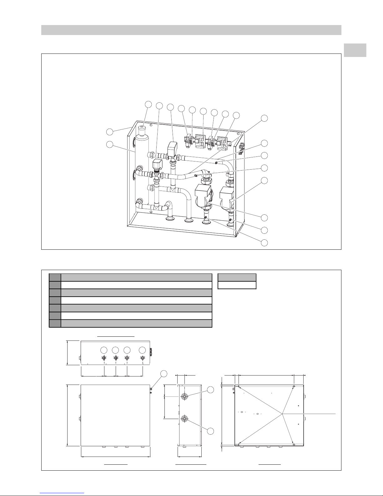
1 - Housing
2 - Mixing cylinder
3 - Automatic air vent valve
4 - Motorised, 3-way valve, zone 1
5 - Motorised, 3-way valve, zone 2
6 - Circulator, zone 1
7 - Circulator, zone 2
8 - Circuit breaker, zone 1
9 - Circuit breaker, zone 2
10 - Circulator terminal strip, zone 1
11 - Circulator terminal strip, zone 2
12 - Control board, zone 1
13 - Control board, zone 2
14 - Outlet water sensor, zone 1
15 - Outlet water sensor, zone 2
16 - Pressure taps for water output measurement, zone 1
17 - Pressure taps for water output measurement, zone 2
2 - PRESENTATION
2.1 - DESCRIPTION
74.5 43 107600
750 260
665
251.5 170130 120
63515 15
185.5
240
127.5
6 5 4 3
7
2
1
2.2 - DIMENSIONS AND WEIGHT
1 Module water inlet connection (generator side) Weight (kg)
2 Module water outlet connection (generator side) 39
3 Outgoing connection, zone 1
4 Outgoing connection, zone 2
5 Return connection, zone 1
6 Return connection, zone 2
7 Holes for electric cables
All connections are 1” male.
4 ø 9 holes
for wall
mounting
Front view Left side view Rear view
View from below
Page 4

GB
4
3 - INSTALLATION
• Protection rating of the module: IP 31.
• The module must be installed in a sheltered location.
• Remove the module's front panel (6 screws on the sides).
• Secure the module to the wall. See the position of the 4 mounting holes in paragraph 2.2.
4 - CONNECTIONS
4.1 - HYDRAULIC CONNECTION
• The module is to be connected on the installation's outgoing line, at the heating module outlet. The module is entered from
above. Connect the outgoing and return line of each zone.
4.2 - ELECTRICAL CONNECTIONS
4.2.1 - GENERAL
• Class 1 apparatus, intended for an installation equipped with a neutral point connection (TT as per NFC 15-100) in
domestic applications.
• Breaking capacity of the circuit breakers for the module: 3 kA as per NFC 61-410.
• Voltage variation tolerance: +/- 10% in operation.
• The electrical connection conduits must be secured.
• Use the cable glands mounted on the unit - see § 4.2.4.
• Ensure that all installation grounds are interconnected.
• Cables are not supplied.
• Consult the module electrical diagram.
• Also consult the installation manuals of the generator and the heater module, and the control’s technical manual.
4.2.2 - DESCRIPTION OF CONNECTIONS
4.2.2.1 - MAINS SUPPLY
• 230 V, single-phase, 50 Hz, input amperage = 1.6 A.
• The electrical power supply must come from protection and disconnecting means (not
supplied) in compliance with the standards and regulations in force. The circuit must be
protected by a two-pole circuit breaker.
• Cable 3G 1.5 mm
2
.
• Power supply to be connected directly on the zone 1 circuit breaker (“Q1”) located in the
module.
4.2.2.2 - CONTROL CONNECTIONS
- Refer to the diagrams in § 4.2.3.
Outgoing line, zone 1
Outgoing line, zone 2
Return, zone 1
Return, zone 2
Generator
Heating module
2-zone floor module
Plate exchanger
NPh
230 Vac
PE
Q1
Caution:
To avoid problems related to electromagnetic disturbances, do not route these cables near power cables.
Page 5

GB
5
P
Q Q
P
A BUS BUS
BUS
Control box
With built-in ambient temperature sensor.
To be installed in zone 1.
Water
temperature,
zone 2
Heating
board
2-ZONE FLOOR MODULE
Water
temperature,
zone 1
Ambient
temperature,
zone 2
Ambient
temperature,
zone 1
Board, zone 2
A2
Board, zone 1
A1
Possible accessory
70250065
(If control box is installed
outside zone 1)
A BUS
- 2-conductor cable, min. size 1 mm
2
.
- Total length of the BUS connection: 40 meters (heating board / control box connection + heating board / zone board if
any connection).
- To be connected on the terminal strip of the boards, zones A1 and A2, located in the module.
A2 A1
Heating
board
Caution:
Be sure to respect
the polarities + and -
P Zone ambient temperature sensor
- For zone 2, Floor: mandatory, supplied with the module.
- For zone 1, Floor: required only if the control unit is not placed in a
location that is representative of the temperature in zone 1.
Caution
:
In this case, the remote zone 1 sensor must be activated through
parameterisation on the control unit (refer to control’s technical manual).
This sensor is proposed as accessory 70250065.
- Wall mounting: the sensor is designed to be mounted in a "Mosaïc" type
(45 x 45), flush-mounted electrical box (not supplied).
It is to be installed in a location that is representative of the temperature
in the zone.
- The sensor must not be installed in corners, on shelves or behind
curtains, near sources or heat or directly exposed to sunlight.
The unit should be installed approximately 1.5 m above the floor.
- Use a 2-conductor cable for installation, minimum size: 0.5 mm
2
and max. length: 25 meters.
- To be connected directly on the corresponding zone board (terminals C and S5).
Q Water temperature probe (Floor zone outgoing line)
- Indicated for informational purposes as it is already connected in the module.
1.50 m
20 cm min.
Ambient Sensor
HEATING MODULE
2-ZONE FLOOR MODULE
HEATING MODULE
Page 6
GB
6
230 V power supply
BUS A
Zone ambient
sensor(s) P
5 - START-UP
5.1 - VERIFICATIONS
• Ensure that the hydraulic connections are properly tight and that the hydraulic system operates correctly:
- purge of circuits,
- valve position,
- hydraulic pressure (1.5 to 3 bar).
• No leaks.
• Proper machine stability.
• Electrical cables and wires are well secured to their connection terminals. Loose terminals can cause heat build-up on the
terminal board and malfunctions.
• Ensure that the electric cables are properly protected from all sheet metal edges or metal parts that could damage them.
• Ensure that control cables and power cables are properly separated.
• Check that the unit is properly grounded.
• Make sure that no tools or any other objects have been left in the machine.
5.2 - CONFIGURATION / SETTING
• Set the button on the installation's control box to OFF.
• Turn installation and module power on.
• On the control unit, configure the system for the "2 Floor Zones" application (parameter 70 = 2); then check and adapt the
parameterization to the installation conditions (consult the control’s technical manual).
• Check that the setpoint settings of the generator regulator are compatible with the "2 Floor Zones" application.
• Check the position of the zone addressing micro-switches (Z1/Z2), see the diagram in § 7.
Before carrying out any work on the machine, make sure that it is switched off and that access to it is prevented.
Any work must be carried out by personnel qualified and authorised to work on this type of machine.
IMPORTANT NOTE
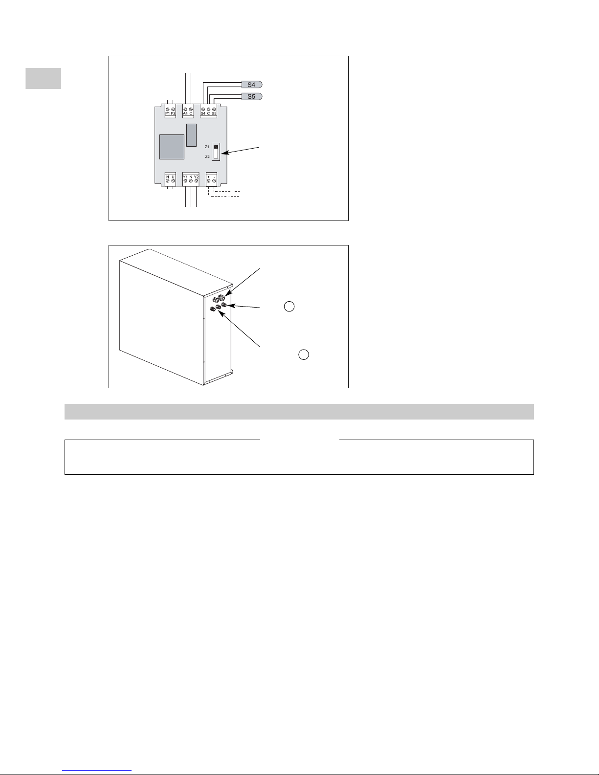
4.2.3 - ZONE BOARD CONNECTION DETAIL
4.2.4 - CABLE ROUTING
230 Vac
BUS
Zone ambient
temperature sensor
Valve control
Pump
control
Valve contact input
Zone addressing
micro-switch
Water temperature sensor
(floor outgoing line)
Page 7

GB
7
5.3 - OPERATION
• Check circulator operation in the generator and the operation of the 2 circulators of the module. Adapt the speed of the
circulators in order to respect the flow rates. For the generator, refer to the corresponding installation manual.
Note:
When the system is off, operation can be forced by changing the parameterization:
- of zone 1 (accelerator on and control valve open) with parameter 65,
- of zone 2 (accelerator on and control valve open) with parameter 66,
- of the generator with parameter 67.
• Check that water is properly circulating in the installation (valve position).
Note:
The mixing valves of each of the module's floor zone outgoing lines are delivered in full open position
(position “1”).
They are equipped with a “3-point” motor for 230 VAC controlled by the zone board:
- Y1 = open control signal,
- N = neutral (common),
- Y2 = close control signal.
When off, it is possible to open the valves by actuating the motor using a 3 mm Allen wrench.
• Purge the installation. Check the bleeders located in the 2-zone module and heating module.
CAUTION:
An incorrect purge could result in malfunctions and damage to the heater of the heating module.
0
10
20
30
40
50
60
70
80
90
00.511.522.53
Water flowrate (m3/h)
Manometric delivery head (kPa) of the circulator
Speed 1
Speed 2
CIRCULATOR SXM 32 - 55
Speed 3
6 - MAINTENANCE INSTRUCTIONS
• Before doing any work on the installation, make sure it is switched off and all power supplies locked out.
• Any work must be carried out by personnel qualified and authorised to work on this type of machine.
IMPORTANT NOTE
• Water flowrate: The module's outgoing water lines
are equipped with 1/4 SAE pressure taps at the inlet
and outlet of each circulator, to enable the pressure
loss to be measured using a hydraulic pressure
gauge. Use the following circulator curves below
(circulator SXM 32 - 55) to find the water flowrate.
• Start the system in the desired operating mode using the control box button (consult the control’s technical manual and the
control box user's guide).
Caution:
At the end of testing and before starting the installation, the forced configuration must be deactivated
and parameters 65, 66 and 67 returned to zero.
Page 8

GB
8
7 - ELECTRICAL DIAGRAM
A1 Control board, zone 1
A2 Control board, zone 2
EV1 Control valve, zone 1
EV2 Control valve, zone 2
M1 Circulator, zone 1
M2 Circulator, zone 2
Q1 Circuit breaker, zone 1
Q2 Circuit breaker, zone 2
S4 Water temperature sensor (outgoing line, zone 1)
S41 Water temperature sensor (outgoing line, zone 2)
S5 Temperature ambiance sensor (zone 1)
Accessory
S51 Temperature ambiance sensor (zone 2)
Component symbols
Q2
PE
XA
Z1
Z2
P2P1 A4 C S4 C S5
NU Y1 N Y2 +-
A2
S41
S51
M2
1
~
N
U
12
XA
11
XA
EV2
BUS
BUS
P2P1 A4 C S4 C S5
NU Y1 N Y2 +-
A1
S4
S5
M1
1
~
N
U
2
XA
1
XA
EV1
Q1
12
11
12
11
12
11
12
11
Z1
Z2
PE N Ph
ELECTRICAL DIAGRAM - M2Z P
10 05 807 - 03
Power supply
230V / 1 / 50
Pump
Water probe
Ambiance
sensor
Pump
Water probe
Ambiance
sensor
(accessory)
GENERAL MAINTENANCE
All equipment must be properly maintained in order to provide optimum performance over time. Faulty maintenance can result in
the cancellation of the product guaranty. Depending on the products, maintenance operations consist in the cleaning of filters (air,
water), internal and external exchangers, casings, and the cleaning and protection of condensate tanks. Treating odours and the
disinfection of room surfaces and volumes also contributes to the cleanliness of the air breathed by users.
• Perform the following operations at least once per year (the frequency of operations depends on the installation and
operating conditions):
- Check the composition and condition of the coolant.
- Check operating points and setpoints.
- Check the safety devices:
- Dusting of electrical boxes.
- Ensure that all electrical connections are properly tight.
- Check the ground connections.
- Check the hydraulic system (cleaning of the filter, water quality, purge, flowrate, pressure etc.).
Page 9

GB
9
Page 10

F
GB
D
P
I
E
Page 11

F
GB
D
P
I
E
Page 12

F
GB
D
P
I
E
Par souci d'amélioration constante, nos produits peuvent être modifiés sans préavis.
Due to our policy of continuous development, our products are liable to modification without notice.
Per garantire un costante miglioramento dei nostri prodotti, ci riserviamo di modificarli senza preaviso.
En el interés de mejoras constantes, nuestros productos pueden modificarse sin aviso prévio.
Unsere Produkte werden laufend verbessert und können ohne V
orankündigung abgeändert werden.
Com o objectivo de uma melhoria constante, os nossos produtos podem ser modificados sem aviso prévio.
R.D. 28 Reyrieux BP 131 01601 Trévoux CEDEX France
Tél. 04 74 00 92 92 - Fax 04 74 00 42 00
T
el. 33 4 74 00 92 92 - Fax 33 4 74 00 42 00
R.C.S. Bourg-en-Bresse B 759 200 728
 Loading...