

Page 1
F
GB
I
E
D
P
MODE D’EMPLOI
INSTRUCTION MANUAL
ISTRUZIONI PER L’USO
MANUAL DE INSTRUCCIONES
BEDIENUNGSANLEITUNG
MANUAL DE INSTRUÇÕES
Octobre 2009 10 11 548 - F.GB.I.E.D.P - 00
Conserver ce mode d’emploi
Save these instructions
Conservate queste istruzioni
Guarde estas instrucciones
Bewahren Sie bitte diese Bedienungsanleitung auf
Guarde estas instruções
SYSTÈMES DE CHAUFFAGE / CLIMATISATION AVEC POMPE À CHALEUR
INVERTER ET CHAUFFAGE ÉLECTRIQUE D’APPOINT INTÉGRÉ
HEATING / COOLING SYSTEMS WITH INVERTER HEAT PUMP
AND BUILT-IN SUPPLEMENTARY ELECTRIC HEATING
SISTEMA DI RISCALDAMENTO / CLIMATIZZAZIONE CON POMPA DI CALORE
INVERTER E RISCALDAMENTO INTEGRATIVO ELETTRICO INTEGRATO
SISTEMAS DE CALEFACCIÓN / CLIMATIZACIÓN CON BOMBA DE CALOR
INVERTER Y CALEFACCIÓN APOYO ELÉCTRICO INTEGRADA
HEIZUNGS-/KLIMAANLAGEN MIT INVERTER-WÄRMEPUMPE UND
INTEGRIERTER ELEKTRISCHER ZUSATZHEIZUNG
SISTEMAS DE AQUECIMENTO / CLIMATIZAÇÃO COM BOMBA DE CALOR
INVERTER E AQUECIMENTO DO COMPLEMENTO ELÉCTRICO INTEGRADO
Page 2

2
GB
CONTENTS
Date of purchase:_____________________________________________________________
Retailer's Name / Address:______________________________________________________
___________________________________________________________________________
Phone number:________________________
DECLARATION OF CONFORMITY
The marking on these products indicates that they are compatible with the essential
requirements of:
- low Voltage Directive 2006/95/CE,
- electromagnetic Compatibility Directive 2004/108/CE
and the corresponding construction standards.
This declaration will become void in case of misusage and / or from non observance though
partial of Manufacturer’s installation and / or operating instructions.
Note
: the heat pump uses R410A refrigerant.
This product is designed for Residential application.
1 - Installation location . . . . . . . . . . . . . . . . . . . . . . . . . . . . . . . . . . . . 3
2 - Electrical power supply instructions . . . . . . . . . . . . . . . . . . . . . . . 3
3 - Safety instructions . . . . . . . . . . . . . . . . . . . . . . . . . . . . . . . . . . . . . 4
4 - Presentation of main elements . . . . . . . . . . . . . . . . . . . . . . . . . . . 5
5 - Operating principle . . . . . . . . . . . . . . . . . . . . . . . . . . . . . . . . . . . . 5
6 - Control unit operation . . . . . . . . . . . . . . . . . . . . . . . . . . . . . . . . . . 6
7 - Maintenance and troubleshooting . . . . . . . . . . . . . . . . . . . . . . . . 11
8 - Troubleshooting . . . . . . . . . . . . . . . . . . . . . . . . . . . . . . . . . . . . . . 12
9 - System operating recommendations . . . . . . . . . . . . . . . . . . . . . . 13
PRODUCT INFORMATION
The following information is required to address all problems or questions relating to the system.
The equipment codes and serial numbers are indicated on their rating plates.
Heat pump
2-zone module
Domestic Hot Water
(DHW) production tank
Product code
Serial No.
Page 3
GB
3
• The installation must be performed by a qualified technician according to the
instructions provided with the appliances.
• Prior to installation, check that the installation's mains voltage corresponds to that indicated
on the rating plate.
1 - INSTALLATION LOCATION
WARNING
• Avoid:
To protect the heat pump from corrosion, avoid installing it in a location where there is a risk
of it being sprayed with seawater or in an aggressive or sulphurous environment (for example,
near a hotspring).
• The equipment room in which certain system components are
installed must be free of gas fumes, flammable gas, high humidity
and high heat.
• Do not store objects near the heat pump so as not to disrupt good
airflow around the exchanger.
CAUTION
• To pre-heat the heat pump, turn on system power at least five (5)
hours prior to operation.
• It is recommended that the power be left on, unless it is not to be
used for an extended period of time.
1. All cables and their installation must comply with current standards and regulations. For
further details, consult your installer.
2. All elements must be properly grounded.
3. The electrical connections must be performed by a qualified technician.
2 - ELECTRICAL POWER SUPPLY INSTRUCTIONS
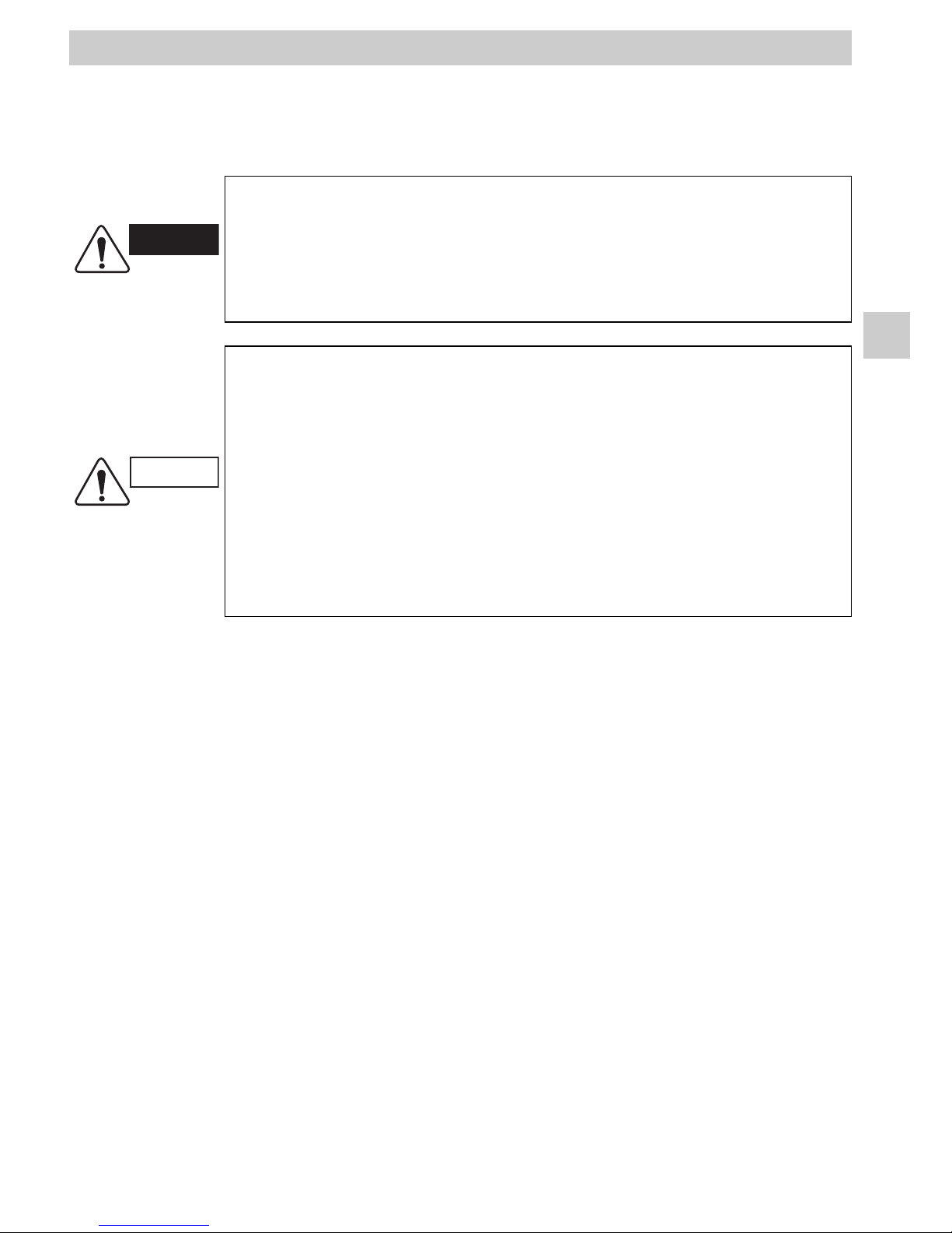
ALERT SYMBOLS
The following symbols used in this manual, alert you to potentially dangerous conditions
to users, service personnel or the appliance:
This symbol refers to a hazard or unsafe practice which can result in
severe personal injury or death.
This symbol refers to a hazard or unsafe practice which can result in
personal injury or product or property damage.
WARNING
CAUTION
Page 4

4
GB
WARNING
• Never touch the apparatus with wet hands.
• Never wet or spray the apparatus with water.
• Never use or store gasoline or any other flammable liquids or
vapours near the apparatus, as such practices are extremely
dangerous.
• Do not remove the protective covers from the apparatus.
CAUTION
• Never turn the unit on or off using the installation's power supply
switch. Use the selector switch on the control unit.
• Do not introduce anything into the heat pump of the air outlet. This
is very dangerous as the fan turns at high speed.
• Do not cool or heat the room too much if babies or invalids are
present.
• This system is not designed to be used by people (including
children) whose physical, sensory or mental capacities are
impaired, or who lack experience or knowledge, unless they are
supervised or have received instructions on how to use the
appliance by a person who is responsible for their safety.
Precautions should be taken to ensure that children do not play with
the appliance or its accessories.
• Consult approved professionals to perform the maintenance and
troubleshooting operations.
• Carefully read these instructions thoroughly before operating the system. If you still
have any difficulties or problems, consult the After-Sales Service Department.
• The system is designed to create a comfortable environment in your home. Use this
only for its intended purpose as described in this Instruction Manual.
3 - SAFETY INSTRUCTIONS
Page 5
GB
5
4 - PRESENTATION OF MAIN ELEMENTS
• The heat pump, installed outside the home, captures heat from the air and delivers it into the
home via a hydraulic system capable of supplying various types of transfer units (floor, lowtemperature radiators, fan-coil units, and Domestic Hot Water (DHW) tank...).
• The supplementary electric heating built into the heat pump provides additional heat in the
event it can no longer supply the required amount of heat (in cases of extreme cold, for
example).
• The built-in control manages the system that supplies the hydraulic system with a water
temperature adapted to current needs and according to the operating mode selected on the
control unit.
• For installations with radiators or fan-coil units, the ambient temperature can be adjusted by
means of commands specific to this type of transfer unit.
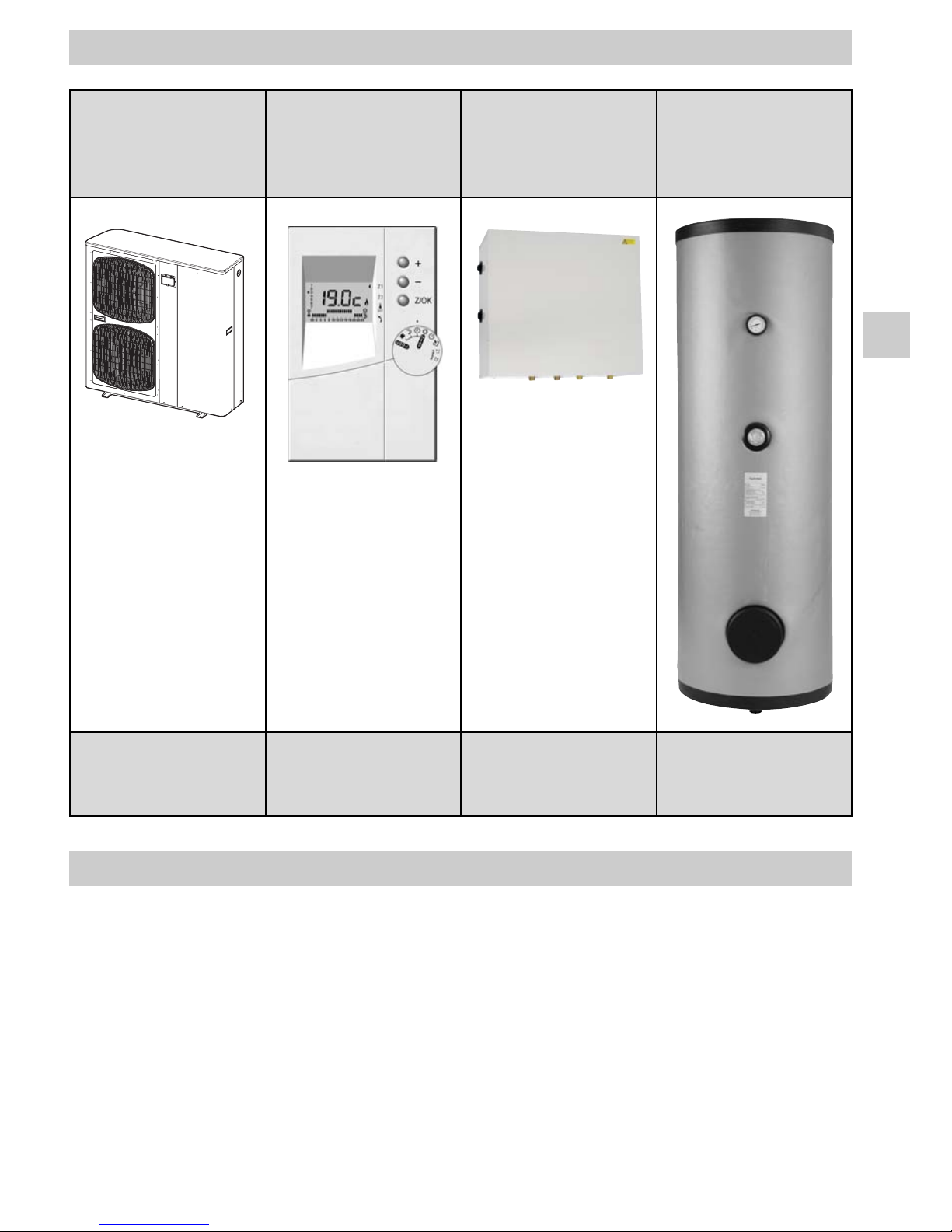
5 - OPERATING PRINCIPLE
Heat pump Control unit
2-zone hydraulic
module
(if installed)
Domestic Hot Water
(DHW) production tank
(if installed)
Installed outside
the home
Installed inside the home
within the unit's operating
environment
Installed in a sheltered
and frost protection
equipment room
Installed in a sheltered
and frost protection
equipment room
Page 6
6
GB
Two cases are possible in the case of an installation with 2 zones:
• zone 2 = floor: the unit displays the temperatures for each zone,
• zone 2 = terminal units: the unit displays either HEAT in heating mode
or COOL in cooling mode. The configuration is determined when commissioned.
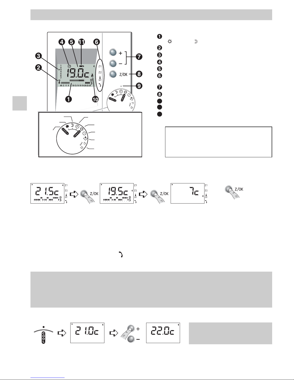
6 - CONTROL UNIT OPERATION
9
10
11
Current program
( : Comfort, : Economy)
Comfort override activated
Current day
Supplementary heating only
Temperatures
Display zone 1, zone 2 (if any)
or outside temperature
Modification or override keys
Validation or zone change key
Button selection mark
Electric supplementary heating ON
DHW cycle in duty (if any)
Economy
Away
Cooling
mode
Hourly program mode
Comfort
Stop
Time setting
Hourly programming
Note: electronic controller configuration
is to be set by a technician during
starting up according the installation
type.
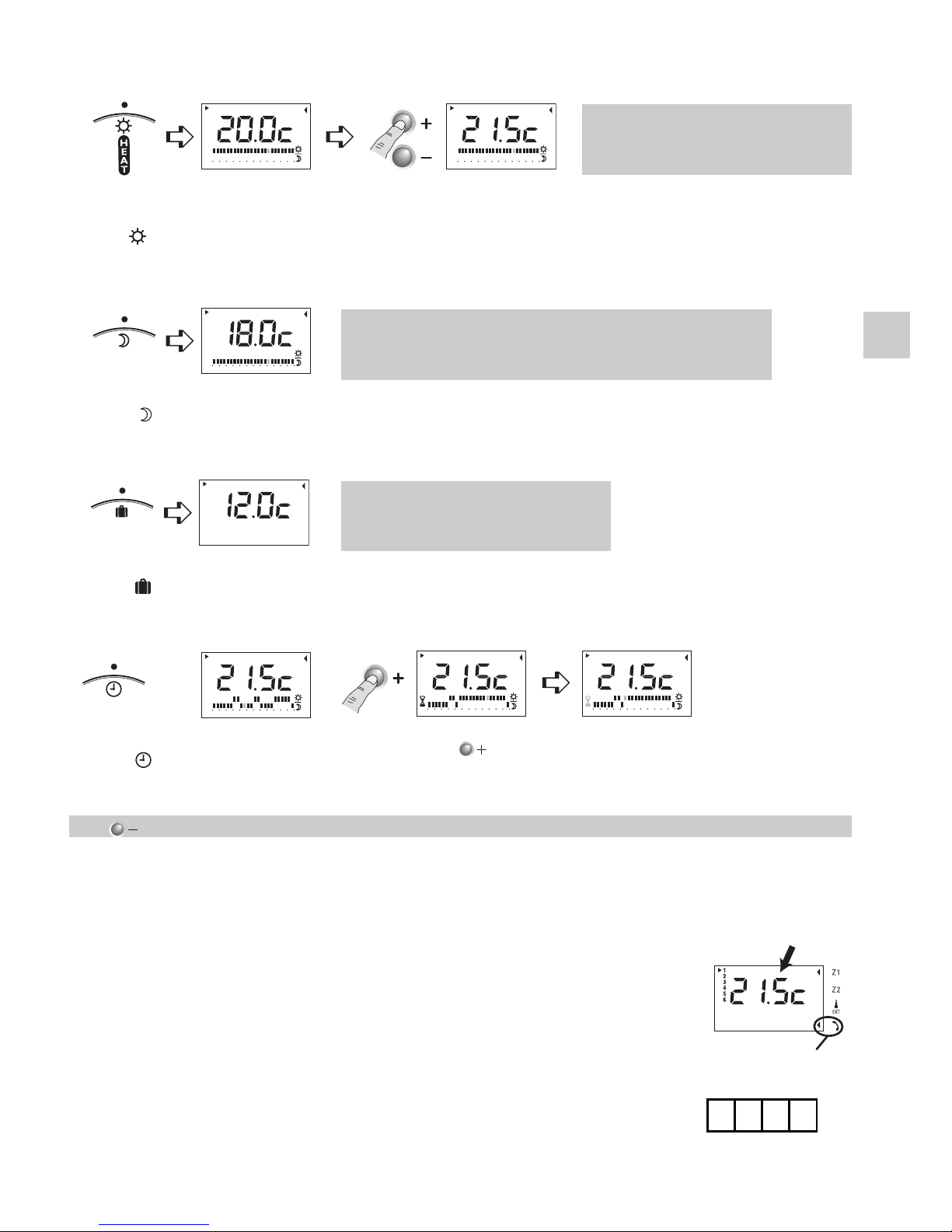
6.1 - TEMPERATURES DISPLAY
Zone selection with key Z/OK
0h 2 4 6 8 1012 14 1618 20 2224
1
2
3
4
5
6
7
0h 2 4 6 8 1012 14 1618 20 2224
1
2
3
4
5
6
7
1
2
3
4
5
6
7
Display of the current
setpoint and program
of zone 1
Display of the current
setpoint and program of
zone 2 (possible)
Outside
temperature
display
At any time, pressing
and holding (5 sec.)
the key will display the
ambient temperature
of the zone
By default, the current set point is displayed.
The cursor is displayed near the symbol when the system is operating in override with a
Typhone 500 telephone remote control unit (Heating mode - ZONE 1 - only).
6.2 - COOLING MODE - If installed - Activated according to the type of installation
1
2
3
4
5
6
7
Set the
knob to
COOL
The setpoint
temperature is
displayed
Cooling setpoint temperature
adjustment
(20°C to 30°C)
The setting mode is exited after 5
seconds if no key is pressed.
Page 7
GB
7
6.3.5 - Set point override by telephone control TYPHONE 500
• Only in heating mode (do not operate in cooling mode).
The user can:
- know the ambient temperature of zone 1,
- know the current set point temperature of zone 1,
- send a common override set point for zone 1 and 2.
During override, zone 1 and 2 operate in Comfort mode with
the new temperature set point.
This override is indicated by an index on the display.
Any action on the rotary knob deactivates the override.
Note:
This function is possible only after entering the password (given by
the installer) by means of the phone keyboard.
New current set point
Phone comfort
override index
6.3 - HEATING MODE
6.3.1 - Comfort mode
0h 2 4 6 8 1012 14 1618 20 2224
1
2
3
4
5
6
7
0h 2 4 6 8 1012141618202224
1
2
3
4
5
6
7
Set the
knob
to
the
Comfort
setpoint is displayed
Set the new Comfort
setpoint from 15°C to 25°C
(ex: 21.5°C)
The setting mode is exited after 5
seconds if no key is pressed.
0h 2 4 6 8 1012 14 1618 20 2224
1
2
3
4
5
6
7
Set the
knob
to
The Economy setpoint
is displayed
The Economy temperature is indexed to the Comfort
temperature (adjustable in the installer menu).
Default value: Economy = Comfort - 2°C.
6.3.2 - Economy mode
1
2
3
4
5
6
7
Set the
knob
to
The frost protection
setpoint is displayed
The frost protection temperature
is 12°C - factory set (adjustable
during installation)
6.3.3 - Long-term absence mode (away) - Frost protection
0h 2 4 6 8 1012 14 1618 20 2224
1
2
3
4
5
6
7
0h24681012141618202224
1
2
3
4
5
6
7
0h24681012141618202224
1
2
3
4
5
6
7
Set the
knob
to
The unit
followings the
programming
Press the key as many
times as necessary to select
a Comfort override
If not pressed for 3 seconds,
the override is validated.
The hourglass icon flashes
6.3.4 - Hourly programming mode
The key enables you to go back during the override duration programming step.
Page 8

8
GB
6.4 - DOMESTIC HOT WATER PREPARATION (DHW)
If installed - Activated according to the type of installation
• Available on installations 1 zone heating only (No cooling).
• Function activated during installation. Actuates the heat pump, in a cyclic way, for an
adapted DHW preparation tank pre-heating.
• A running DHW cycle can be stopped by setting the system to “OFF” (Then start it again
in the selected function).
• Out of the heating season, it is possible to activate this DHW function by selecting the cool
mode (=“Summer”). At that time, message “DHW” is appearing on the display.
6.5 - TIME AND DATE ADJUSTMENT
1
2
3
4
5
6
7
1
2
3
4
5
6
7
1
2
3
4
5
6
7
Set the
knob
to
The current
day flashes
Select the desired
day and validate by
pressing OK
Set the hour
using + or - and
validate by
pressing OK
Set the minutes
using + or - and
validate by
pressing OK
0h 2 4 6 8 1012 14 1618 20 2224
1
2
3
4
5
6
7
0h 2 4 6 8 1012141618202224
1
2
3
4
5
6
7
Set the
knob on
PROG Z1
The 1sttime slot
flashes
Validate and continue
to the next day.
Repeat the procedure
for each day
Repeat the
procedure for
each time slot
Ex.: Comfort
from 7h to 9h,
from 12h to 14h,
from 19h to 23h
6.6 - PROGRAMMING
To modify the programming for zone 2 (if this one is activated), set the knob to and
repeat the operations above
6.7 - STOP
1 h comfort
1 h reduced
Set the
knob
to
Page 9
GB
9
DHW (domestic hot water) preparation
temperature (if function is activated)
Heat pump control status
Outside temperature Heat pump mode control status
Installation water return temperature Outlet status, Support heater Elec. - 1
Installation water outlet temperature Outlet status, Support heater Elec. - 2
Resulting water temperature setpoint,
ZONE 1
Outlet status, Support heater Elec. - 3
Resulting water temperature setpoint,
ZONE 2
Outlet status - water pump ZONE 1
Water temperature, ZONE 1 Outlet status - water pump ZONE 2
Water temperature, ZONE 2 (floor) ZONE1 valve control status
Ambient Temperature ZONE 1 ZONE 2 (floor) valve control status
Ambient Temperature ZONE 2 (floor)
DHW valve control status (if the
function is activated)
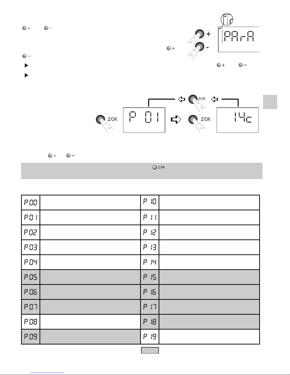
6.8 - PARAMETERISATION
From any knob position, simultaneously press and hold keys
and for 5 seconds, until the screen displays PArA, then
select User / Installer menu.
To move from the user menu to the installer menu, press or
:
- = user menu: certain parameters may only be consulted,
- = installer menu: protected access by password for
modification (for installer use only).
Select the first parameter by
pressing on Z/OK.
Press the or keys to shift from one parameter to another.
To exit the parameterisation menu, press and hold for 5 seconds or modify the position
of the selector knob.
List of parameters that can be consulted by the user:
2
1
Access to the 1stparameter (P01) Display of the parameter
value
1 : User
2 : Installer
Simultaneously press and
hold the and keys
for 5 seconds
Parameters available for installations
with 2 ZONES
Page 10

10
GB
6.9 - ALARMS
If an alarm message appears, contact the After-Sales Service.
The unit
displays:
Heat pump fault. Automatic or manual reset (**).
In heating mode, the heat pump fault causes the installation to switch to Frost
Protection mode. It is possible to restart in heating mode by pressing and
holding OK.
The symbol is displayed.
Caution, in this case, heating is provided only by the supplementary electric
heating.
F
Communication fault with heat pump.
Same action as for Gr alarm.
Electric supplementary heating fault.
Installation water return probe fault.
Output water probe fault installation.
Water probe fault, zone 1 (in the case of 2 zones only).
Water probe fault, zone 2 (in the case of 2 zones only).
High water temperature fault. Manual reset (*).
Outside air probe fault.
Ambiance probe fault Z1.
Ambiance probe fault, Z2 (in the case of 2 zones floor).
Communication or system fault.
Communication fault with zone 1 board (in the case of 2 zones).
Communication fault with zone 2 board (in the case of 2 zones).
Heat pump water flow fault. Manual reset (*).
DHW valve fault (if function is activated).
Note: Flashing display without alarm message indicates that the water temperature is momentary
not convenient for the heat pump. Call the After-Sales Service only if this fact persists.
(*) Manual reset by stopping ("OFF") the device with the selector knob of mode (or by
disconnecting the power of the apparatus). Call the after-sales service.
or
Page 11
GB
11
• A yearly verification (or during a restart) is to be performed by an approved technical service
centre.
• Cleaning.
7 - MAINTENANCE AND TROUBLESHOOTING
WARNING
1. Be safe! Turn the unit off and disconnect the electric power
supplies.
2. Do not pour water on the apparatus to clean them. This will
damage the internal components and cause an electric shock
hazard.
CAUTION
1. Never use solvents or powerful chemical products. Do not wipe
plastic parts using very hot water.
2. As certain metal edges may be sharp, handle elements with
caution when cleaning them.
3. Certain components (such as the heat pump exchanger) and the
filter installation must be cleaned regularly.
These operations must be performed by an approved technical
service centre.
Page 12

12
GB
8 - TROUBLESHOOTING
PROBLEM POSSIBLE CAUSE ACTION
The control unit is
turned off.
Power supply circuit breaker has tripped (open).
Problem in the heat pump's control circuit.
Contact the After-Sales
Service Department.
Contact the After-Sales
Service Department.
The system does not
operate at all.
The function switch is set to "OFF".
An alarm is displayed on the control unit (see list in
paragraph 6.9).
Power supply circuit breaker has tripped (open).
Line voltage very low.
Select the desired
mode.
Contact the After-Sales
Service Department.
Contact the After-Sales
Service Department.
Consult the installer.
The heat pump starts
but stops rapidly.
Obstacle in front of the unit's exchanger. Clear a space around
the unit.
Insufficient heating (or
cooling).
Doors and / or windows are open.
Heat source in cooling mode.
Setpoints (set on the control unit) are inappropriate (too
low in heating mode / too high in cooling mode).
Incorrect settings on radiator and fan-coil unit
thermostats (if any).
Air filter on terminal units (if any) obstructed or dirty.
Low water pressure on the hydraulic system
Hydraulic system poorly purged.
Faulty outdoor unit defrosting.
Close.
Remove the source of
heat.
Modify the settings.
Modify the settings.
Clean the filter.
Add water to the
system.
If the problem
continues, call AfterSales Service.
Purge the system.
If the problem
continues, call AfterSales Service.
Contact the After-Sales
Service Department.
Page 13

GB
13
• Make sure that doors and windows are correctly closed.
• Correctly set the temperature setpoints to the desired values.
Each additional degree of heating (or cooling) results in a significant increase in energy
consumption.
• Remember to use the “Eco” and “Frost-Protection” modes.
• For reversible installations, be sure to respect a minimum
rest period (“OFF”) of 2 to 3 hours
when switching from heating mode to cooling mode (or from cooling mode to heating mode).
• Ensure that all terminal units, if any, are in good operating condition (air inlets and outlets
clear, clean filter).
Note
:
In the event of a power outage, system operation returns automatically when the power is
restored, with the same settings as before the outage.
However, the clock will need to be reset if the power outage exceeds 6 hours (see § 6.5).
9 - SYSTEM OPERATING RECOMMENDATIONS
Page 14

F
GB
I
E
D
P
Page 15

F
GB
I
E
D
P
REMARQUE : Ce symbole et ce système de recyclage s'appliquent uniquement aux pays de
l’UE. Ils ne s'appliquent pas aux pays des autres régions du monde.
NOTE: This symbol mark and recycle system are applied only to EU countries and not applied to
the countries in the other area of the world.
NOTA : Questo simbolo e il sistema di riciclaggio sono validi soltanto per i paesi dell’Unione
Europea e non sono validi per i paesi nel resto del mondo
.
NOTA : Este símbolo y el sistema de reciclaje solamente son para países de la UE y no son
aplicables a países de otras áreas del mundo.
HINWEIS : Dieses Symbol und Recycle-System gelten nur für Länder der Europäischen Union,
nicht für andere Länder der Welt
.
NOTA : Este símbolo e o sistema de reciclagem são aplicados apenas aos países da UE e não
são aplicados a países de outras áreas do mundo.
F
GB
I
E
D
P
F
GB
I
E
D
P
Votre produit est conçu et fabriqué avec des matériels et des composants de qualité supérieure qui peuvent être recyclés
et réutilisés.
En fin de vie, il doit être éliminé séparément des ordures ménagères.
Nous vous prions donc de confier cet équipement à votre centre local de collecte/recyclage.
Dans l’Union Européenne, il existe des systèmes sélectifs de collecte pour les produits électriques et électroniques usagés.
Aidez-nous à conserver l’environnement dans lequel nous vivons !
Les appareils contiennent fréquemment des matières qui, si elles sont traitées ou éliminées de manière inapropriées,
peuvent s’avérer potentiellement dangereuses pour la santé humaine et pour l’environnement.
Cependant, ces matières sont nécessaires au bon fonctionnement de votre appareil ou de votre machine. Pour cette
raison, il vous est demandé de ne pas vous débarrasser de votre appareil ou machine usagé avec vos ordures ménagères.
Your product is designed and manufactured with high quality materials and components which can be recycled and reused.
At end of livetime, it should be eliminated separately from your household waste.
Please dispose of this equipment at your local community waste collection/recycling centre.
In the European Union there are separate collection systems for used electrical and electronic products.
Please help us to conserve the environment we live in!
Some equipments contain substances that are considered dangerous to the environment and human health if they are
disposed of carelessly.
These substances, however, are required for your apparatus or machine to work properly. For this reason, it is requested
that it not be disposed of with other household waste at the end of its service life.
Il vostro prodotto è stato costruito da materiali e componenti di alta qualità, che sono riutilizzabili o riciclabili.
Alla fine della sua vita utile deve essere smaltito separatamente dai rifiuti domestici.
Vi preghiamo di smaltire questo apparecchio in un centro di raccolta differenziata locale.
Nell'Unione Europea esistono sistemi di raccolta differenziata per prodotti elettrici ed elettronici.
Aiutateci a conservare l'ambiente in cui viviamo!
Gli apparecchi contengono spesso dei materiali che, se trattati od eliminati in modo non adeguato, possono dimostrarsi
potenzialmente pericolosi per la salute umana e per l'ambiente.
Tuttavia, questi materiali sono necessari per il corretto funzionamento del vostro apparecchio o della vostra macchina. Per
questo motivo, si richiede di non eliminare il proprio apparecchio o macchina usata assieme ai rifiuti domestici comuni.
Los productos están diseñados y fabricados con materiales y componentes de alta calidad, que pueden ser reciclados y reutilizados.
Al final de su ciclo de vida, no se debe desechar con el resto de residuos domésticos. Por favor, deposite su viejo “televisor” en el
punto de recogida de residuos o contacte con su administración local.
En la Unión Europea existen sistemas de recogida específicos para residuos de aparatos eléctricos y electrónicos.
Por favor, ayúdenos a conservar el medio ambiente!
Los aparatos a menudo contienen materiales que, si son tratados o eliminados de forma inadecuada, pueden convertirse en
potencialmente peligrosos para la salud humana y para el medio ambiente.
No obstante, estos materiales son necesarios para el buen funcionamiento de su máquina. Por esta razón, le rogamos
encarecidamente que al final de la vida útil de su aparato, no lo tire junto con la basura doméstica, sino que lo recicle
adecuadamente.
Ihr Produkt wurde entworfen und hergestellt mit qualitativ hochwertigen Materialien und Komponenten, die recycelt und
wiederverwendet werden können.
Am Ende ihrer Nutzungsdauer muss er getrennt vom Hausmüll eliminier werden sollen.
Bitte entsorgen Sie dieses Gerät bei Ihrer örtlichen kommunalen Sammelstelle oder im Recycling Centre.
In der Europäischen Union gibt es unterschiedliche Sammelsysteme für Elektrik- und Elektronikgeräte.
Helfen Sie uns bitte, die Umwelt zu erhalten, in der wir leben!
Die Geräte enthalten häufig Bestandteile aus bestimmten Werkstoffen, die bei einer nicht ordnungsgemäßen Behandlung
oder Entsorgung eine Belastung für die menschliche Gesundheit und Umwelt darstellen.
Diese Werkstoffe sind jedoch für die korrekte Funktionsweise Ihres Gerätes oder Maschine notwendig. Daher bitten wir
Sie, Ihr(e) ausgediente(s) Gerät/Maschine nicht in den Hausmüll zu geben.
O seu produto foi concebido e produzido com materiais e componentes de alta qualidade que podem ser reciclados e
reutilizados.
No final da sua vida útil deverá ser descartado separadamente do seu lixo doméstico.
Por favor, entregue este equipamento no seu ponto local de recolha / reciclagem.
Na União Europeia existem sistemas de recolha separados para produtos eléctricos e electrónicos usados.
Por favor, ajude-nos a conservar o ambiente em que vivemos!
Os aparelhos contêm, frequentemente, substâncias que, se forem tratadas ou eliminadas de maneira incorrecta, podem
revelar-se potencialmente perigosas para a saúde humana e para o ambiente.
Contudo, estas matérias são necessárias para o bom funcionamento do aparelho ou da máquina. Por este motivo, solicitase que não se deite fora o aparelho ou a máquina com os resíduos domésticos.
Page 16

F
GB
I
E
D
P
Par souci d'amélioration constante, nos produits peuvent être modifiés sans préavis.
Due to our policy of continuous development, our products are liable to modification without notice.
Per garantire un costante miglioramento dei nostri prodotti, ci riserviamo di modificarli senza preaviso.
En el interés de mejoras constantes, nuestros productos pueden modificarse sin aviso prévio.
Unsere Produkte werden laufend verbessert und können ohne Vorankündigung abgeändert werden.
Com o objectivo de uma melhoria constante, os nossos produtos podem ser modificados sem aviso prévio.
R.D. 28 Reyrieux BP 131 01601 Trévoux CEDEX France
Tél. 04 74 00 92 92 - Fax 04 74 00 42 00
Tel. 33 4 74 00 92 92 - Fax 33 4 74 00 42 00
R.C.S. Bourg-en-Bresse B 759 200 728
 Loading...