

Technibel iSeries, GR9FI30LTR5IAA, GR9FI40LTR5IAA, GR9FI50LTR5IAA Technical Data & Service Manual
Page 1

TECHNICAL DATA
& SERVICE MANUAL
OUTDOOR UNIT:
GR9FI30LTR5IAA
GR9FI40LTR5IAA
GR9FI50LTR5IAA
SPLIT SYSTEM AIR CONDITIONER
May 2016
iSeries
GR9FI30LTR5IAA
AEI1G 30 LT
AEI1G 40-50 LT
GR9FI4-50 0LTR5IAA
Page 2

TABLE OF CONTENTS
1 SCOPE...................................................................................................................................4
2 DIMENSIONAL DATA AND EXTERIOR APPEARANCE........................................... 5
3 TECHNICAL SPECIFICATIONS .....................................................................................7
4 REFRIGERANT CIRCUIT ............................................................................................... 10
5 ELECTRICAL WIRING DIAGRAM ...............................................................................13
6 PRINCIPLE OF FUNCTIONING...................................................................................15
7 COMPONENTS OPERATION......................................................................................... 17
8 DEFROST............................................................................................................................19
9 PROTECTIONS .................................................................................................................21
10 COMPONENT DESCRIPTION .......................................................................................23
11 DIAGNOSTIC TABLE ......................................................................................................26
12 TROUBLESHOOTING...................................................................................................... 27
13 COMPONENT REPLACEMENT ......................................................................................30
14 PACKAGING...................................................................................................................... 39
15 LABELS ...............................................................................................................................41
Page 3

REVISION NOTES
Rev. Date Author Checked Comments
00 01/10/2014
MDG GV First release.
01 14/11/2014
02 20/01/2015
GV MDG
Added Scope, Packaging and Labels sections. Added
exterior appearance description. Fixed CDT sensor table.
GV MDG
30-40-50
Page 4

1 Scope
This specification document is applied to the outdoor units mentioned below used for air to air heat
pump to be delivered
UNIT MODEL TABLE
DECLARATION OF CONFORMITY “CE”
Units described in this document conform to the protection requirement of the following EC directives:
•••• EMC Directive 2004/108/EC
•••• LVD (Low Voltage Directive) 2006/95/EC
•••• RoHS 2 Directive 2011/65/EU
Standards:
• EN378-2:2008 + A1:2009
• EN 60335-1:2002+A11:2004+A12:2006+A13:2008+A14:2010
• EN 60335-2-40 :2003+A11:2004+A12:2009+A1:2006
• EN 55014-1:2006 + A1:2009
• EN 55014-2:1997 + A1:2001+ A2:2008
• EN 61000-3-2:2006+A1:2009+A2:2009
• EN 61000-3-3:2008
• EN 61000-3-11:2000
• EN 61000-3-12:2005
CODICE
TECHNIBEL
387107115
387107116
387107117
GR9FI30LTR5IAA
GR9FI40LTR5IAA
GR9FI50LTR5IAA
Page 5

2 Dimensional data and exterior appearance
Exterior appearance – color Top/front and side/rear panel: silver
(F1936)
Fan Guard and valve covering: gray
(RAL7042)
Material Panel: zinc-coated steel sheet
Fan guard and valve covering: polypropylene
Painting 2 layers,
20 µ or more for electro coating (lower layer)
40 µ or more for polyester powder paint coating (top layer)
Total Coating thickness is 60 µ or more.
240 hrs salt spray test
GR9FI30LTR5IAA
Page 6

Exterior appearance – color Top/front and side panel: silver
(F1936)
Fan Guard and valve covering: gray
(RAL7042)
Material Panel: zinc-coated steel sheet
Fan guard and valve covering: polypropylene
Painting 2 layers,
20 µ or more for electro coating (lower layer)
40 µ or more for polyester powder paint coating (top layer)
Total Coating thickness is 60 µ or more.
240 hrs salt spray test
GR9FI40LTR5IAA
GR9FI50LTR5IAA
Page 7

3 Technical specifications
AIR AIR
COOLING Pdesignc W 2680
+35°C SEER 6,11
A++
HEATING Pdesignh W 3030
Average -10°C SCOP 3,82
A
ERP Ecodesign - EN14825
COOLING
Minimum W 1370
+35°C OU / 27/19°C IU
Maximum W 3650
HEATING
Minimum W 930
+7/6°C OU / +20°C IU
Maximum W 3880
-7°C/-8°C OU / + 20° C IU Maximum W 2650
-10°C/-11°C OU / + 20° C IU Maximum W 2350
-22°C/-21°C OU / + 20° C IU Maximum W 2150
EN14511
Power supply V/Ph/Hz 230/1/50
Power input (max.) W/A 1550/6,90
R410A standard refrigerant charge kg 0,81
Compressor type Single Rotary
Fan speed Auto
Sound pressure (max.) dB(A) 40
Liquid pipe mm (inch") 6,35 (1/4")
Gas pipe mm (inch") 9,52 (3/8)"
Total lenght of pipes (standard load) m 7,5
Total lenght of pipes (additional load) m 15
Maximum lenght difference (total) m 10
GR9FI30LTR5IAA
Page 8

AIR AIR
COOLING Pdesignc W 3670
+35°C SEER 6,06
A++
HEATING Pdesignh W 4020
Average -10°C SCOP 4,01
A
ERP Ecodesign - EN14825
COOLING
Minimum W 1010
+35°C OU / 27/19°C IU
Maximum W 4060
HEATING
Minimum W 910
+7/6°C OU / +20°C IU
Maximum W 4870
-7°C/-8°C OU / + 20° C IU Maximum W 3510
-10°C/-11°C OU / + 20° C IU Maximum W 3250
-22°C/-21°C OU / + 20° C IU Maximum W 2980
EN14511
Power supply V/Ph/Hz 230/1/50
Power input (max.) W/A 1550/6,90
R410A standard refrigerant charge kg 1,1
Compressor type Single Rotary
Fan speed Auto
Sound pressure (max.) dB(A) 44
Liquid pipe mm (inch") 6,35 (1/4")
Gas pipe mm (inch") 9,52 (3/8)"
Total lenght of pipes (standard load) m 7,5
Total lenght of pipes (additional load) m 15
Maximum lenght difference (total) m 10
GR9FI50LTR5IAA
Page 9

AIR AIR
COOLING Pdesignc W 5215
+35°C SEER 6,74
A++
HEATING Pdesignh W 4070
Average -10°C SCOP 4,16
A
ERP Ecodesign - EN14825
COOLING
Minimum W 900
+35°C OU / 27/19°C IU
Maximum W 5650
HEATING
Minimum W 1030
+7/6°C OU / +20°C IU
Maximum W 5290
-7°C/-8°C OU / + 20° C IU Maximum W 3900
-10°C/-11°C OU / + 20° C IU Maximum W 3300
-22°C/-21°C OU / + 20° C IU Maximum W 3040
EN14511
Power supply V/Ph/Hz 230/1/50
Power input (max.) W/A 1790/7,80
R410A standard refrigerant charge kg 1,3
Compressor type Twin Rotary
Fan speed Auto
Sound pressure (max.) dB(A) 41
Liquid pipe mm (inch") 6,35 (1/4")
Gas pipe mm (inch") 12,77 (1/2)"
Total lenght of pipes (standard load) m 7,5
Total lenght of pipes (additional load) m 20
Maximum lenght difference (total) m 10
GR9FI50LTR5IAA
Page 10

4 Refrigerant circuit
Note:
- In heating mode the refrigerant flow is in the opposite direction of the COOL arrows
- INV: 4-way valve
- EXP: Electronic Expansion Valve
- COM: Compressor
GR9FI30LTR5IAA
Page 11

Note:
- In heating mode the refrigerant flow is in the opposite direction of the COOL arrows
- INV: 4-way valve
- EXP: Electronic Expansion Valve
- COM: Compressor
GR9FI40LTR5IAA
Page 12

Note:
- In heating mode the refrigerant flow is in the opposite direction of the COOL arrows
- INV: 4-way valve
- EXP: Electronic Expansion Valve
- COM: Compressor
GR9FI50LTR5IAA
Page 13

5 Electrical wiring diagram
Legend
A1 Control pcb OAT Outdoor Air Sensor
F1 Main fuse
6,3x32 - 10A / 250V
CDT Compressor Discharge Sensor
F2 Comm. Fuse, RS485 bus cable
5x20 - 100mA / 250V
OCT Outdoor Coil Sensor
SW1 Dip-switch EEV Electronic Expansion Valve
JP1/2/3 Jumpers CCH Crankcase Heater
EF Electromagnetic Interference
Filter
ER Drip tray heater
CM Compressor CWP Condensate water pipe heater
FM Fan motor EI PFC Inductor
INV 4-way valve
Page 14

Settings
Jumpers
JP1: Factory use. Default: open.
JP2: Defrost type selection. Default: closed.
JP3: Heating only option. Default: open (heating and cooling).
Dip-switch:
SW1: Factory use. Default: 1=Off, 2=Off.
Note:
Jumper and dip-switch settings can be changed only when unit is powered off.
Page 15

6 Principle of functioning
Heating mode
When the unit is in heating mode, the system will regulate the heating capacity delivered to the room to
increase the room air temperature (RAT) to the set point (SPT) and to balance the thermal load of the
room to keep the set point temperature.
The following rules apply to heat mode functioning:
- Compressor and fan start when RAT is 1°C or more below the SPT
- Compressor and fan stop if RAT is 2°C or more above the SPT, or if RAT is 1°C above the SPT for
more than 1 hour
During the first 3 minutes of operation:
- Compressor and fan run at a fixed speed (2 minutes at low speed and 1 minute at intermediate
speed)
- EEV is open at a fixed value
After the first 3 minutes of operation, compressor and fan speeds are regulated by:
- the thermal load calculation
- the level of protecion of the system
During heating mode, 4-way valve is active.
Cooling mode
When the unit is in cooling mode, the system will regulate the cooling capacity delivered to the room to
decrease the room air temperature (RAT) to the set point (SPT) and to balance the thermal load of the
room to keep the set point temperature.
The following rules apply to cool mode functioning:
- Compressor and fan start when RAT is 1°C or more above the SPT
- Compressor and fan stop if RAT is 2°C or more below the SPT, or if RAT is 1°C below the SPT for
more than 1 hour
During the first 3 minutes of operation:
- Compressor and fan run at a fixed speed (2 minutes at low speed and 1 minute at intermediate
speed)
- EEV is open at a fixed value
After the first 3 minutes of operation, compressor and fan speeds are regulated by:
- the thermal load calculation
- the level of protecion of the system
During cooling mode, 4-way valve is deactivated.
Page 16

Dehumidification (dry) mode
When the unit is in dry mode, the system will operate according to the following table:
Notes:
- When dry mode is active, the temperature of the room could decrease below the setpoint
temperature if the thermal load of the room is low.
- During dry mode, 4-way valve is deactivated.
Auto mode
When the unit is in auto mode (auto cooling or auto heating), the system will switch between heating
and cooling mode to maintain the room air temperature (RAT) to the set point temperature (SPT).
The system will switch between heating and cooling mode if one of the following conditions is met:
- Cooling Heating if at least 3 minutes have passed since the compressor was stopped and ∆T ≤ -3
- Cooling Heating if at least 1 hour have passed since the compressor was stopped and ∆T ≤ -1
- Heating Cooling if at least 3 minutes have passed since the compressor was stopped and ∆T ≥ 3
- Heating Cooling if at least 1 hour have passed since the compressor was stopped and ∆T ≥ 1
where:
- ∆T = RAT – SPT
Fan mode
When system is in fan mode:
- Compressor and fan are stopped.
- 4-way valve is deactivated
- Indoor fan runs at the selected speed
RAT DRY LEVEL DESCRIPTION
≥ SPT + 2°C 0 Unit operates normally in cooling mode.
< SPT + 2°C
≥ SPT - 1°C
1
Unit operates with a fixed cooling demand.
Indoor fan switches between very low speed and
low speed every 30 seconds.
< SPT - 1°C
≥ 10°C
2
Unit cycles between a period of operation with a
fixed cooling demand (3 minutes) and a period of
non operation (9 minutes).
Indoor fan switches between very low speed and
low speed every 30 seconds.
< 10°C DRY OFF Unit is off.
Page 17

7 Components operation
Compressor
The compressor runs if the following conditions are met:
- At least 3 minutes have passed since the power supply was switched on
- At least 3 minutes have passed since the compressor was stopped
- At least 6 minutes have passed since the previous compressor start
- There is no active alarm on the outdoor and indoor units
- There is no active protection
- There is a thermal load demand in the room
Compressor stops if:
- At least 3 minutes have passed since compressor start
- There is no capacity demand
or if:
- At least 3 minutes have passed since compressor start
- Protection level is too high
or if there is any alarm active.
Fan
The fan runs only when the compressor is running and starts right after the compressor.
The fan can also run without compressor in the following conditions:
- Overheating on the outdoor heat exchanger (cooling or dry mode)
- Overheating on the power electronics
Electronic Expansion Valve (EEV)
EEV is managed based on the system conditions to meet the maximum efficiency point of operation and
to guarantee a safe operation of the system.
Every time power supply is switched on, or once per day if compressor is not running, EEV runs a reset
cycle necessary to find the correct position of the valve. During this reset cycle, EEV is completely closed
and then reopened to a fixed value.
4-way valve
4-way valve is activated when:
- System is in heating mode
4-way valve is deactivated when:
- System is in cooling, dry or fan only mode
- System is off
- Defrost is active
Page 18

Crankcase heater
Crankcase heater around the compressor is used to prevent refrigerant migration and mixing with
crankcase oil when the unit is off, and to prevent condensation of refrigerant in the crankcase of the
compressor. The crankcase heater keeps refrigerant at a temperature higher than the coldest part of the
system.
Crankcase heater is activated if the following conditions are met:
- Compressor is stopped
- OAT il lower than 5°C
- Difference between CDT and OAT is lower than 18,5°C
When crankcase is active, it will be deactivated if one of the following condition is met:
- Compressor starts
- OAT increases above 5°C
- Difference between CDT and OAT is higher than 21,5°C
Drip tray heater (built-in) and condensation water heater (accessory)
The drip tray heater and the condensation water heater prevent condensation freezing on the drip tray
and the condensation water pipe.
The heaters are activated if the system is in heating mode and one or more of the following conditions
are met:
- OAT is lower than 0°C
- Defrost is active
- Less than 5 minutes have passed since last defrost
When heaters are active, they will be deactivated if all of the following conditions are met:
- OAT is higher than 2°C
- Defrost is not active and more than 5 minutes have passed since last defrost
Page 19

8 Defrost
A defrost starts if one of these conditions is satisfied (see graph below):
- OCT falls below L1 line and compressor is running for at least 35 minutes without defrost
- OCT falls below L2 line and compressor is running for at least 60 minutes without defrost
A defrost ends if one of these conditions is satisfied:
- OCT rise above 14°C and defrost has been active for at least 2 minutes
- defrost has been active for 12 minutes
Removing the jumper JP2, the defrost end contitions will change according to the following:
- OCT rise above 24°C and defrost has been active for at least 5 minutes
- defrost has been active for 15 minutes
Page 20

Before reversing the cycle at the beginning and at the end of the defrost, the compressor ramps down to
decrease the pressure inside the circuit:
When defrost is active:
- 4-way valve is deactivated
- Compressor runs at a fixed speed (if no protection is active)
- EEV is open at a fixed value
- Fan is off
When defrost ends:
- 4-way valve is reactiavted
- EEV is opened at a fixed value for 5 minutes
Page 21

9 Protections
The unit is equipped with an automatic system of protections. These protections, if active, will limit the
speed of the compressor in order to run the system in a safe operating area.
Protections, when active, reduce the speed of the compressor linearly down to its minimum speed. If the
level of protection is too high, compressor is stopped until no protection will be active.
Overheating on outdoor unit heat exchanger
This protection checks the temperature on the outdoor coil (OCT) to avoid overheating and overpressure
of the heat exchanger.
This protection is active only in cooling or dry mode and starts to limit the compressor speed when OCT
is higher than 55°C.
Overheating on indoor unit heat exchanger
This protection checks the temperature on the indoor coil (ICT) to avoid overheating and overpressure of
the heat exchanger and reduces the high pressure noise inside the indoor unit.
This protection is active only in heating mode and starts to limit the compressor speed when ICT is
higher than 40°C(*).
Notes:
- (*) ICT threshold may vary depending on the model of the indoor unit
- If High Power option is active, protection will start at higher values of ICT, increasing the heating
capacity
Freeze-up on indoor unit heat exchanger
This protection checks the temperature on the indoor coil (ICT) to avoid freezing of the indoor unit heat
exchanger.
This protection is active only in cooling or dry mode and starts to limit the compressor speed when ICT
is lower than 8°C.
Furthermore, if the unit is stopped because of this protection, in order to drip away all the condensed
water on the indoor coil, it will not restart until ICT is higher than 8°C.
Overheating on the compressor
This protection checks the compressor’s discharge temperature (CDT) to avoid overheating of the
compressor.
This protection is always active and starts to limit the compressor speed when CDT is higher than 90°C.
Overheating on the power electronic
This protection checks the temperature of the electronic power module connected to the heatsink. The
temperature sensor is built into the module, so there is no direct access to it.
This protection is always active and starts to limit the compressor speed when power electronic
temperature is higher than 90°C.
Page 22

Over power consumption from the power supply
This protection checks the power consumption of the outdoor unit (but not of the indoor unit) to avoid
an excessive power consumption than can damage the pcb and the unit.
This protection is always active and limits the compressor speed to keep the outdoor unit power
consumption below 1800W.
Overcurrent of the compressor
This protection checks the current consumption of the compressor to avoid damage to the compressor
and to the pcb.
This protection is always active and limits the compressor speed to keep the current consumption of the
compressor below 8A.
Page 23

10 Component description
Compressor
type HERMETIC, SINGLE ROTARY, DC INVERTER
model 5RS102XBE01
oil RB68A or Freol Alpha 68M
refrigerant R410A
motor BRUSHLESS MOTOR
n. of poles 6
rated output 700 W
winding resistance
(@20 °C)
U-V: 0,858 Ω V-W: 0,858 Ω U-W: 0,858 Ω
overload protector CS-7L 115 (WAKO ELECTRIC OR EQUIVALENCE)
Fan Motor
model ZW465B58 ( ) – ZW465B57 ( )
motor BRUSHLESS MOTOR
n. of poles 8
rated output 20 W
rpm variable, 200 ÷ 850
winding resistance
(@25 °C)
BRN (W) - BLK (U) :
206 Ω
WHT (V) - BLK (U) :
206 Ω
BRN (W) - WHT (V) :
206 Ω
4-way Valve
model SHF-4H-23U (valve) - SHF-4-10L3 (coil)
coil rating AC 220-240V 50/60Hz
coil resistance 1440 Ω ± 7% at 20°C
Electronic Expansion Valve
model CAM-BD15EX-1 (valve) - ZCAM-MD12EX-9M-B (coil)
coil rating DC 12V
coil resistance 46 Ω ± 4% at 20°C
Crankcase Heater
power 30 W
resistance 1760 Ω ± 10% at 20°C
Drip Tray Heater
power 75 W
resistance 700 Ω ± 10% at 20°C
GR9FI30LTR5IAA
GR9FI40LTR5IAA
MOD.30
MOD.40
Page 24

Compressor
type HERMETIC, TWIN ROTARY, DC INVERTER
model SNB130FGBMT
oil FV 50S
refrigerant R410A
motor BRUSHLESS MOTOR
n. of poles 6
rated output 900 W
winding resistance
(@20 °C)
U-V: 0,98 Ω V-W: 0,98 Ω U-W: 0,98 Ω
overload protector EXTERNAL
Fan Motor
model ZW465B57
motor BRUSHLESS MOTOR
n. of poles 8
rated output 20 W
rpm variable, 200 ÷ 850
winding resistance
(@25 °C)
BRN (W) - BLK (U) :
206 Ω
WHT (V) - BLK (U) :
206 Ω
BRN (W) - WHT (V) :
206 Ω
4-way Valve
model SHF-7K-34U (valve) - SHF-4-10L3 (coil)
coil rating AC 220-240V 50/60Hz
coil resistance 1440 Ω ± 7% at 20°C
Electronic Expansion Valve
model CAM-BD15EX-1 (valve) - ZCAM-MD12EX-9M-B (coil)
coil rating DC 12V
coil resistance 46 Ω ± 4% at 20°C
Crankcase Heater
power 30 W
resistance 1760 Ω ± 10% at 20°C
Drip Tray Heater
power 75 W
resistance 700 Ω ± 10% at 20°C
GR9FI50LTR5IAA
Page 25

Sensors
OCT: Outdoor Coil Temperature. Used for:
- EEV management
- Fan management
- Protection against overheating of the heat exchanger (cooling or dry mode)
- Defrost cycle management (heating mode)
OAT: Outdoor Air Temperature. Used for:
- EEV management
- Fan management
- Defrost cycle management
- Crankcase heater management
- Base heater management
CDT
: Compressor Discharge Temperature. Used for:
- EEV management
- Protection against overheating of the compressor
- Crankcase heater management
T OCT CDT OAT
[°C]
Resistance
[Kohm]
Voltage
[Vdc]
Resistance
[Kohm]
Voltage
[Vdc]
Resistance
[Kohm]
Voltage
[Vdc]
-40
351,078 2,442 351,078 2,470 349,100 2,442
-35
251,577 2,402 251,577 2,462 250,300 2,402
-30
182,451 2,351 182,451 2,451 181,600 2,350
-25
133,827 2,286 133,827 2,437 133,300 2,285
-20
99,221 2,206 99,221 2,419 98,860 2,205
-15
74,316 2,111 74,316 2,396 74,408 2,111
-10
56,202 2,000 56,202 2,367 56,050 1,999
-5
42,894 1,875 42,894 2,331 42,800 1,874
0
33,024 1,737 33,024 2,287 32,970 1,736
5
25,607 1,590 25,607 2,234 25,570 1,589
10
20,017 1,439 20,017 2,171 20,000 1,438
15
15,769 1,288 15,769 2,099 15,760 1,287
20
12,513 1,141 12,513 2,016 12,510 1,141
25
10,000 1,002 10,000 1,924 10,000 1,002
30
8,045 0,873 8,045 1,823 8,048 0,873
35
6,514 0,756 6,514 1,715 6,518 0,756
40
5,306 0,652 5,306 1,602 5,311 0,652
45
4,348 0,560 4,348 1,485 4,353 0,560
50
3,583 0,480 3,583 1,367 3,588 0,480
55
2,968 0,411 2,968 1,250 2,973 0,411
60
2,472 0,352 2,472 1,137 2,477 0,352
65
2,068 0,301 2,068 1,028 2,073 0,302
70
1,739 0,258 1,739 0,925 1,743 0,258
75
1,469 0,221 1,469 0,829 1,473 0,222
80
1,246 0,190 1,246 0,741 1,250 0,191
85
1,061 0,164 1,061 0,660 1,065 0,164
90
0,9078 0,141 0,9078 0,587 0,911 0,142
95
0,7795 0,122 0,7795 0,521 0,782 0,123
100
0,6718 0,106 0,6718 0,463 0,674 0,107
Page 26

11 Diagnostic table
When unit is working properly:
- DL3 is solid ON
- DL4 is solid ON if the indoor unit is switched ON, otherwise it’s OFF
Page 27

12 Troubleshooting
ERROR LIST
Rank Meaning
System
behaviour
Cause Solution
Power supply surge or
over voltage.
Power supply voltage
dip or interruption.
Power supply fast
transient or burst.
Check the quality of the power
supply.
Bad earth connection. Check that all the earth cables are
correctly connected, expecially the
outdoor pcb's earth cable and the
compressor's earth.
Bad connection
between outdoor and
the heatsink.
Check that the outdoor pcb is
properly connected to the heatsink
and that the screws on the pcb are
properly mounted with the right
torque. Check that there is enough
thermal paste between the pcb and
the heatsink.
EEV damaged. Check the EEV functioning. A
malfunctioning on the expansion
valve may cause liquid flood back on
the compressor.
1 PFC (Power Factor
Controller)
protection:
automatic
protection against
power supply
disturbances and
instabilities.
Compressor and fan
are stopped.
The system restarts
automatically after
3 minutes.
Outdoor pcb damaged. Only if the error is recurrent, change
the outdoor pcb.
Bad communication bus
connection between
outdoor and indoor
unit.
Check that connections between C1
and C2 on outdoor and indoor
terminal block is consistent (C1
terminals connected together, C2
terminals connected together).
Normal cable used
instead of shielded
cable.
Be sure to use a shielded
communication cable for serial
connection.
Wrong communication
address.
Be sure to have set the correct
address on every indoor unit. Follow
unit specific installation instructions.
2 Communication
error between the
outdoor unit and
the indoor unit.
Compressor and fan
are stopped after
30 seconds of
missing
communication.
The system restarts
automatically as
soon as the
communication is
recovered.
Bad earth connections. Check that earth cables are properly
connected to every terminal.
Check that the shield of the
communication cable is properly
connected to every terminal.
Chech that all internal earth cable are
properly connected.
Page 28

Communication fuses
blown.
Check the communication fuse on
outdoor unit.
Check the communication fuse on
indoor unit (only certain models).
Indoor unit not
powered on.
Check that the indoor unit has power
supply and that the unit is working.
Outdoor or indoor unit
pcb out of order.
Check that all the pcbs are powered
on.
Be sure that power supply has not
been connected to the
communication terminals.
Check that there are no burnt signes
on the pcbs, in particular close to
communication cables.
Compressor damaged. Check that there is no continuity
between the phases of the
compressor and the earth (dielectric
strength).
3 Error on the indoor
unit.
Compressor and fan
are stopped.
The system restarts
automatically as
soon as the error
on the indoor unit is
solved.
An error occurred on
the indoor unit.
Follow specific indoor unit
troubleshooting.
Bad connection
between the fan
motor's module and the
heatsink, or missing fan
module's heatsink.
Check that the fan motor module is
properly connected to the heatsink
and that the screws on the module
are properly mounted with the right
torque. Check that there is enough
thermal paste between the fan
module and the heatsink.
The rear of the outdoor
unit is obstructed.
Remove the obstruction.
4 Automatic
protection against
overheating on the
power electronics
(fan motor
module).
Compressor and fan
are stopped.
The system restarts
automatically after
3 minutes.
Incorrect fan operation.
Check that fan works properly.
Fan motor
disconnected.
Check the fan motor connector.
Fan motor blocked /
obstructed.
Remove the obstruction.
Fan motor damaged. Check if the fan motor starts. If it
does not start correctly, change the
fan motor.
5 Automatic
protection against
fan motor
overcurrent.
Compressor and fan
are stopped.
The system restarts
automatically after
3 minutes.
Outdoor pcb damaged. Only if the error is recurrent, change
the outdoor pcb.
Page 29

Bad connection
between the outdoor
pcb and the heatsink.
Check that the outdoor pcb is
properly connected to the heatsink
and that the screws on the pcb are
properly mounted with the right
torque. Check that there is enough
thermal paste between the pcb and
the heatsink.
The rear of the outdoor
unit is obstructed.
Remove the obstruction.
6 Automatic
protection against
overheating on the
power electronics
(compressor
module).
Compressor and fan
are stopped.The
system restarts
automatically after
3 minutes.
Incorrect fan operation.
Check that fan works properly.
Power supply surge or
under voltage.
Check the quality of the power
supply.
There is some air or
moisture inside the
refrigerant circuit.
Be sure to have correctly pulled the
vacuum of the system. In case, pull
the vacuum again and recharge the
outdoor unit with the correct amount
of refrigerant.
Damaged compressor. Check windings of the compressor.
Bad earth connection. Check that all the earth cables are
correctly connected.
Fan damaged. Check that fan motors of indoors and
outdoor units work properly.
7 Automatic
protection against
compressor
overcurrent.
Compressor and fan
are stopped.
The system restarts
automatically after
3 minutes.
Lack of refrigerant in
the refrigerant circuit.
Check the refrigerant amount in the
unit, find and repair a possible
leakage and recharge the unit with
the correct refrigerant amount.
8 OCT (Outdoor Coil
Temperature)
sensor fault.
Compressor and fan
are stopped.
The system restarts
as soon as the
sensor is repaired.
Sensor out of order or
disconnected (check
wiring diagram).
Reconnect or replace the sensor.
9 OAT (Outdoor Air
Temperature)
sensor fault.
Compressor and fan
are stopped.
The system restarts
as soon as the
sensor is repaired.
Sensor out of order or
disconnected (check
wiring diagram).
Reconnect or replace the sensor.
10 CDT (Compressor
Discharge
Temperature)
sensor fault.
Compressor and fan
are stopped.
The system restarts
as soon as the
sensor is repaired.
Sensor out of order or
disconnected (check
wiring diagram).
Reconnect or replace the sensor.
Page 30

13 Component replacement
GR9FI30LTR5IAA
Page 31

GR9FI 30-40-50LTR5IAA
Page 32

GR9FI30LTR5IAA
Page 33

GR9FI30LTR5IAA
Page 34

GR9FI30LTR5IAA
Page 35

GR9FI40-50 LTR5IAA
Page 36

GR9FI40-50 LTR5IAA
Page 37

GR9FI40-50 LTR5IAA
Page 38

GR9FI40-50 LTR5IAA
Page 39
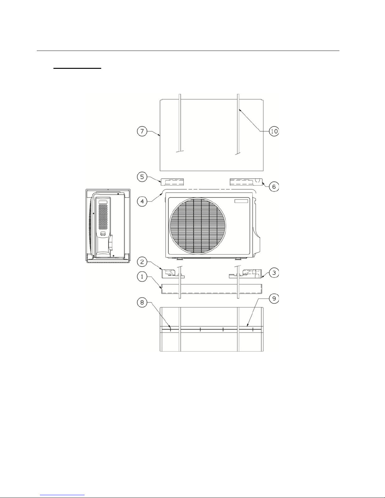
14 Packaging
1: bottom carton box 6: upper right PS shield
2: lower left PS shield 7: carton box
3: lower right PS shield 8: staple
4: polietylene sheet 9: scotch tape
5: upper left PS shield 10: PP band
GR9FI30 LTR5IAA
Page 40

1: bottom carton box 6: upper left PS shield 11: PP band
2: lower left PS shield 7: upper right PS shield
3: lower PS shield 8: carton box
4: lower right PS shield 9: staple
5: polietylene sheet 10: scotch tape
GR9FI40-50 LTR5IAA
Page 41

15 Labels
Energy labels
GR9FI30 LTR5IAA
Page 42

GR9FI40 LTR5IAA
Page 43

GR9FI50 LTR5IAA
Page 44

Rating labels
Page 45

Technibel is a TRADE mark of NIBE ENERGY SYSTEMS FRANCE, used under licence.
.
IMPORTED & DISTRIBUTED BY
ARGOCLIMA SPA - Via Alfeno Varo, 35 - Alfianello (BS) Italy
 Loading...