

Technibel HKE 189R5I, HKE 369R57I, HKE 259R57I, HKE 709R7I, HKE 909R7I Installation Manual And Operating Instructions
...Page 1
GB
INSTALLATION MANUAL
Inverter split air to water heat pump - Indoor unit
HKE 189R5I
HKE 259R57I
HKE 369R57I
HKE 489R57I
HKE 609R57I
HKE 709R7I
HKE 909R7I
Page 2
2
GB
IMPORTANT!
Please read before installation
This air conditioning system meets strict safety and
operating standards.
For the installer or service person, it is important to install or
service the system so that it operates safely and efficiently.
For safe installation and trouble-free operation, you must:
• Carefully read this instruction booklet before beginning.
• Follow each installation or repair step exactly as shown.
• Observe all local, state and national electrical codes.
• Pay close attention to all warning and caution notices given in
this manual.
•The unit must be supplied with a dedicated electrical line.
This symbol refers to a hazard or unsafe practice which can
result in severe personal injury or death.
This symbol refers to a hazard or unsafe practice which can
result in personal injury or product or property damage.
If necessary, get help
These instructions are all you need for most installation sites
and maintenance conditions.
If you require help for a special problem, contact our sale /
service outlet or your certified dealer for additional instructions.
In case of improper installation
The manufacturer shall in no way be responsible for improper
installation or maintenance service, including failure to follow the
instructions in this document.
SPECIAL PRECAUTIONS
• During installation, connect before the refrigerant system and
then the wiring one; proceed in the reverse orden when
removing the units.
When wiring
ELECTRICAL SHOCK CAN CAUSE SEVERE
PERSONAL INJURY OR DEATH. ONLY A
QUALIFIED, EXPERIENCED ELECTRICIANS
SHOULD ATTEMPT TO WIRE THIS SYSTEM.
•
Do not supply power to the unit until all wiring and tubing are
completed or reconnected and checked, to ensure the grounding.
• Highly dangerous electrical voltages are used in this system.
Carefully refer to the wiring diagram and these instructions
when wiring.
Improper connections and inadequate grounding can cause
accidental injury and death.
• Ground the unit following local electrical codes.
• The Yellow / Green wire cannot be used for any connection
different from the ground connection.
• Connect all wiring tightly. Loose wiring may cause overheating
at connection points and a possible fire hazard.
• Do not allow wiring to touch the refrigerant tubing,
compressor, or any moving parts of the fan.
• Do not use multi-core cable when wiring the power supply and
control lines. Use separate cables for each type of line.
When transporting
Be careful when picking up and moving the indoor and outdoor
units. Get a partner to help, and bend your knees when lifting to
reduce strain on your back. Sharp edges or thin aluminium fins
on the air conditioner can cut your fingers.
When installing...
... In a room
Properly insulate any tubing run inside a room to prevent
"sweating", which can cause dripping and water damage to walls
and floors.
... In moist or uneven locations
Use a raised concrete base to provide a solid level foundation
for the outdoor unit.
This prevents damage and abnormal vibrations.
... In area with strong winds
Securely anchor the outdoor unit down with bolts and a metal
frame. Provide a suitable air baffle.
... In a snowy area (for heat pump-type systems)
Install the outdoor unit on a raised platform that is higher than
drifting snow. Provide snow vents.
When connecting r
efrigerant tubing
• Keep all tubing runs as short as possible.
• Use the flare method for connecting tubing.
• Apply refrigerant lubricant to the matching surfaces of the flare
and union tubes before connecting them; screw by hand and
then tighten the nut with a torque wrench for a leak-free
connection.
• Check carefully for leaks before starting the test run.
NOTE:
Depending on the system type, liquid and gas lines may be
either narrow or wide. Therefore, to avoid confusion, the
refrigerant tubing for your particular model is specified as narrow
tube for liquid, wide tube for gas.
When servicing
• Turn the power OFF at the main power board before opening
the unit to check or repair electrical parts and wiring.
• Keep your fingers and clothing away from any moving parts.
• Clean up the site after the work, remembering to check that no
metal scraps or bits of wiring have been left inside the unit
being serviced.
• Ventilate the room during the installation or testing the
refrigeration system; make sure that, after the installation, no
gas leaks are present, because this could produce toxic gas
and dangerous if in contact with flames or heat-sources.
WARNING
CAUTION
WARNING
NOTE: This symbol mark and recycle system are applied only to EU countries and not applied to the countries in the other area
of the world.
Your product is designed and manufactured with high quality materials and components which can be recycled and reused.
This symbol means that electrical and electronic equipment, at their end-of-life, should be disposed separately from your household
waste.
Please dispose of this equipment at your local community waste collection / recycling centre.
In the European Union there are separate collection systems for used electrical and electronic products.
Please help us to conserve the environment we live in!
Page 3
3
GB
SUMMARY
1 - GENERALITIES
1.1 - GENERAL SUPPLY CONDITIONS
• Generally speaking, the material is transported at the consignee’s risk.
• The consignee must immediately provide the carrier with written reserves if he finds any damage caused during transport.
1.2 - RECOMMENDATIONS
• Prior to all servicing or other actions on the equipment, installation, commissioning, operation, or maintenance, the
personnel in charge of these operations shall become familiar with the instructions and recommendations provided in the
installation manual of the unit as well as the elements of the project's technical file.
• The personnel responsible for receiving the unit must conduct a visual inspection in order to identify all damage to which
the unit may have been subjected during transport: refrigerating circuit, electrical cabinet, cassis and cabinet.
• The unit must be installed, started, maintained, serviced by qualified and authorised personnel, in compliance with the
requirements of all directives, laws and regulations and in accordance with standard trade practices.
• During installation, troubleshooting and maintenance operations, the use of pipes as a step: under the stress, the pipe may
rupture and the refrigerant may cause serious burns
1.3 - VOLTAGE
• Before carrying out any operation, check that the voltage indicated on the unit corresponds to the mains voltage.
• Before initiating maintenance or servicing on the installation, check that its power supply is disconnected and locked out.
1.4 - USE OF EQUIPMENT
• This device is designed for heating buildings.
This appliance is not designed to be used by people (including children) whose physical, sensory or mental
capacities are impaired, or who lack experience or knowledge, unless they are supervised or have received
instructions on how to use the appliance by a person who is responsible for their safety. Children must be
supervised to ensure that they do not play with the appliance or its accessories.
1.5 - OPERATING CONDITIONS
• Refer to the technical specifications, the nominal conditions and operating limitations in the technical manual.
MARKING
This product marked conforms to the essential requirements of the Directives:
- Low voltage no. 2006/95/EC.
- Electromagnetic Compatibility no. 2004/108/EC.
1 - Generalities . . . . . . . . . . . . . . . . . . . . . . . . . . . . . . . . . . . . . . . . . . 3
2 - Presentation . . . . . . . . . . . . . . . . . . . . . . . . . . . . . . . . . . . . . . . . . 4
3 - Installation . . . . . . . . . . . . . . . . . . . . . . . . . . . . . . . . . . . . . . . . . . . 7
4 - Connections . . . . . . . . . . . . . . . . . . . . . . . . . . . . . . . . . . . . . . . . . 9
5 - Accessories . . . . . . . . . . . . . . . . . . . . . . . . . . . . . . . . . . . . . . . . . 16
6 - Starting . . . . . . . . . . . . . . . . . . . . . . . . . . . . . . . . . . . . . . . . . . . . 16
7 - Maintenance instruction . . . . . . . . . . . . . . . . . . . . . . . . . . . . . . . 19
8 - Wiring diagrams . . . . . . . . . . . . . . . . . . . . . . . . . . . . . . . . . . . . . 20
1 - Only the following indoor units are to be used with the outdoor units indicated below:
Indoor units Outdoor units
HKE 189R5I ----> GRFP 189R5I
HKE 259R57I ----> GRFP 259R5I or R7I
HKE 369R57I ----> GRFP 369R5I or R7I
HKE 489R57I ----> GRFP 489R5I or R7I
HKE 609R57I ----> GRFP 609R5I or R7I
HKE 709R7I ----> GRFP 709R7I
HKE 909R7I ----> GRFP 909R7I
2 - See the combinations allowed for the NF PAC (Heat Pump) label in the technical instructions.
3 - For the installation of the outdoor unit, please consult the manual supplied with the unit.
NOTE
IMPORTANT
- Water system drawing . . . . . . . . . . . . . . . . . . . . . . . . . . . . . . . 29 4
Page 4
4
GB
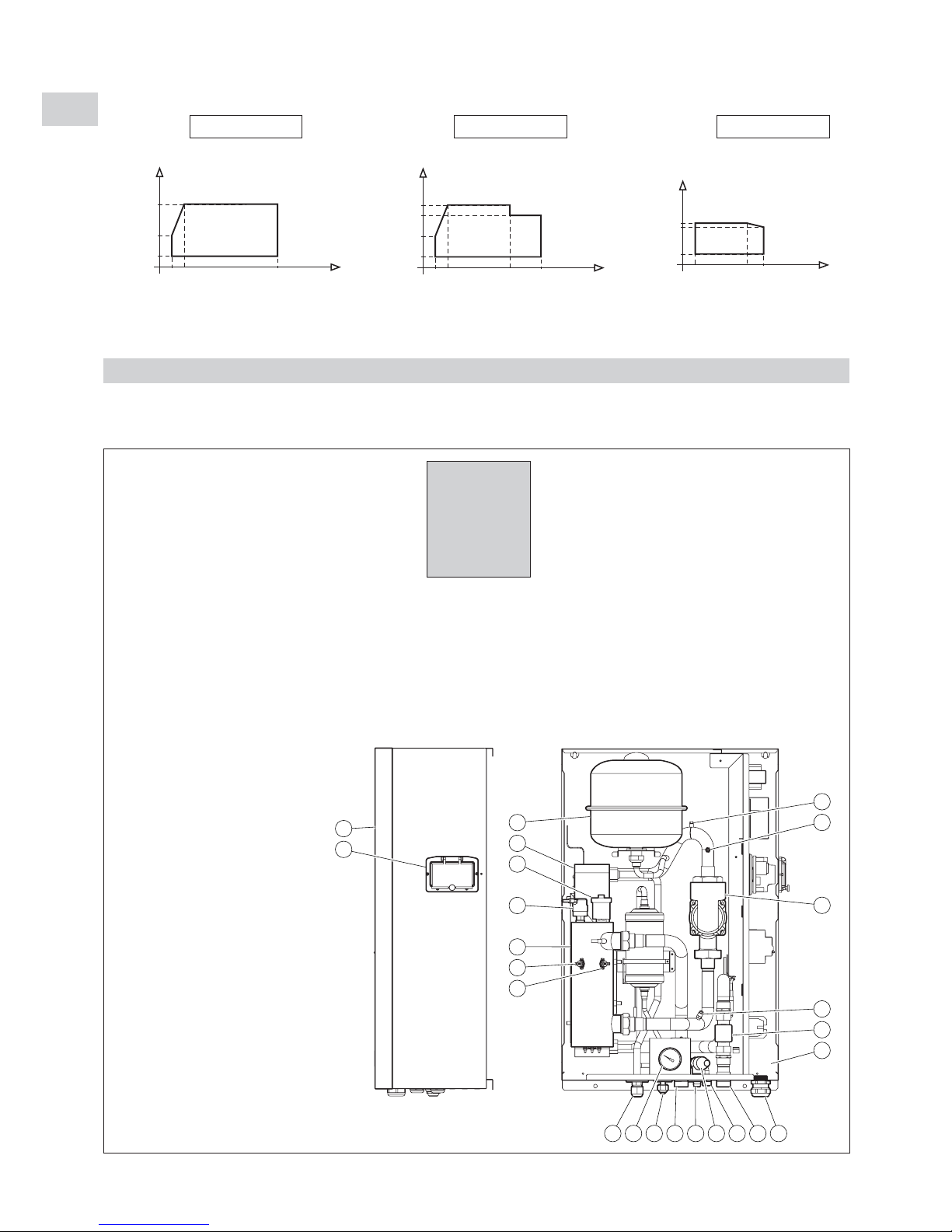
2 - PRESENTATION
2.1 - DESCRIPTION
2.1.1 - GENERAL
• Reminder:
- Water system pressure: 2 bar.
- Operating limits:
1 - Plate type heat exchanger.
2 - Electric heater:
HKE 189R:
• 3 kW : 1
st
stage = 1.5 kW; 2ndstage = 1.5 kW.
• 4.5 kW : 1ststage = 3 kW; 2ndstage = 1.5 kW.
HKE 259R, 369R and 489R:
• 4 kW : 1
st
stage = 2 kW; 2ndstage = 2 kW.
• 6 kW : 1ststage = 4 kW; 2ndstage = 2 kW.
HKE 609R:
• 6 kW : 1
st
stage = 3 kW; 2ndstage = 3 kW.
• 9 kW : 1ststage = 6 kW; 2ndstage = 3 kW.
HKE 709R and 909R:
• 8 kW : 1
st
stage = 4 kW; 2ndstage = 4 kW.
• 12 kW : 1ststage = 8 kW; 2ndstage = 4 kW.
3 - Automatic air vent valve.
4 - Water pressostat.
5 - Automatic reset safety thermostat.
6 - Manual reset safety thermostat.
7 - Circulator pump.
8 - Surge tank.
9 - Manual air vent valve.
10 - Hydraulic system pressure gauge.
11 - Safety valve.
12 - Flow detector.
13 - Water inlet connection.
14 - Water outlet connection.
15 - Filling / drainage of the water
system.
16 - Safety valve drain connection.
17 - Flare gas connector.
18 - Flare liquid connector.
19 - Electrical cable passage.
20 - Water system pressure tap for flow
control.
21 - Cover.
22 - Communication module access window.
23 - Electrical box (see in paragraph 2.1.2).
HKE 189R
HKE 259R
HKE 369R
HKE 489R
HKE 609R
HKE 709R
HKE 909R
9
20
7
20
12
23
8
1
3
4
2
6
5
17 10 18 14 16 11 15 13 19
21
22
Materials:
- Copper piping.
- Stainless steel water heat exchanger.
- Painted sheet metal cabinet.
25
35
45
50
35
20-16 -10
5
18
20
35
4310
Outdoor dry air
temperature (°C)
Outdoor dry air
temperature (°C)
Water output
temperature (°C)
Water output
temperature (°C)
Heating mode Cooling mode
HKE 369R / 489R / 609R
25
35
50
35
-16 -10
Outdoor dry air
temperature (°C)
Water output
temperature (°C)
Heating mode
HKE 189R / 259R / 709R / 909R HKE 189R / 259R / 369R / 489R /
609R / 709R / 909R
Page 5
5
GB
12
11
8
4
3
10
9
5
7
6
2
1
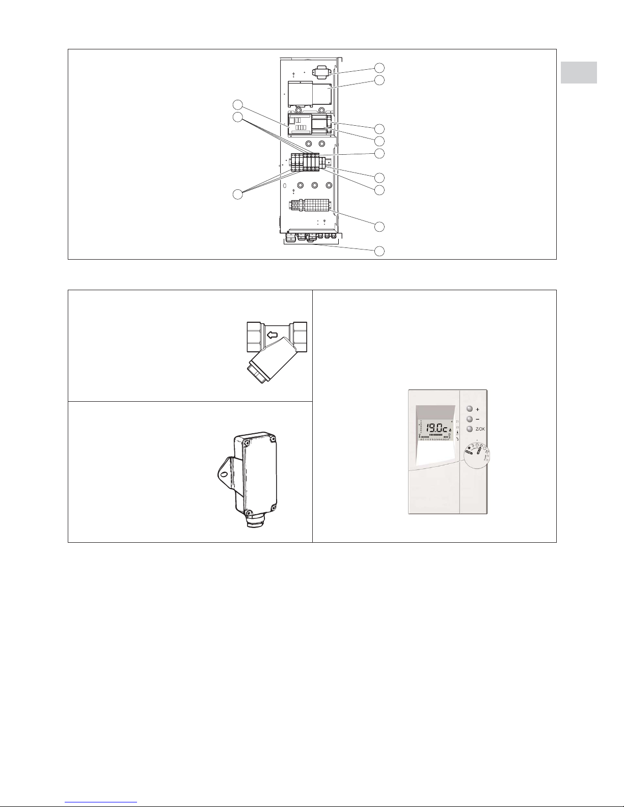
1 - Electrical cable passage.
2 - Terminal strip.
3 - Heating element circuit breakers.
4 - Heating element contactors.
5 - Circulator contactors.
6 - Fault relays.
7 - Water flow rate relay.
8 - Heating control board.
9 - Communication module CC1.
10 - Control circuit circuit-breaker.
11 - Indoor unit board.
12 - Transformer.
2.1.2 - ELECTRICAL BOX
• Hydraulic filter:
- 3/4” FF for HKE 189R and 259R.
- 1” FF for HKE 369R, 489R and 609R.
- 1”1/4 for HKE 709R and 909R.
• Outside temperature sensor:
- Installed in a box with cable gland.
Note:
This sensor must be installed in
a location that is sheltered from
inclement weather.
See details in paragraph 3.4.
• Control unit:
- Plastic wall-mounted control unit.
- Dimensions: height = 128 mm
width = 86 mm
depth = 34 mm
- Colour: White
- Class lll
- IP 30
2.1.3 - ACCESSORIES INCLUDED WITH THE APPARATUS
Page 6
6
GB
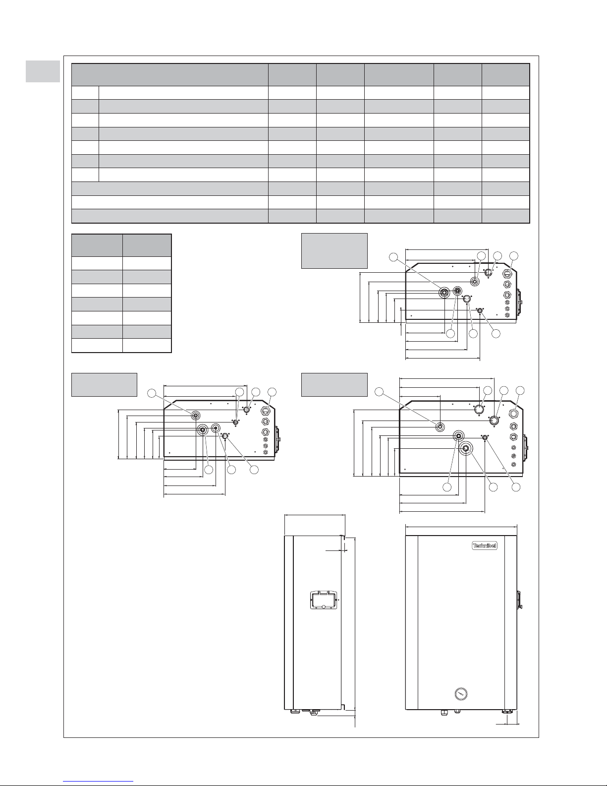
2.2 - DIMENSIONS AND WEIGHT
A
C
B
15.5
45
15.5
184
246
290.5
352
328
392
40.5
96
125
133.5
178
220.5
4 1 7
5
6 2 3
151
184
246
290.5
340
392
96
125
133.5
161
193
220.5
3 1 7
4
5 6 2
194
282
316
406
379
450
116
167
174
216
247
299.5
2 1 7
4
6 5 3
HKE
189R
HKE
259R
HKE
369R/489R/609R
HKE
709R
HKE 909R
1 Water inlet connection 3/4” male 3/4” male 1” male 1”1/4 male 1”1/4 male
2 Water outlet connection 3/4” male 3/4” male 1” male 1”1/4 male 1”1/4 male
3 Water circuit fill / drain 1/2” male 1/2” male 1/2” male 1/2” male 1/2” male
4 Safety valve connection and drainage - - - - -
5 Gas refrigerant connection 1/2” flare 5/8” flare 5/8” flare 3/4” flare 3/4” flare
6 Liquid refrigerant connection 1/4” flare 3/8” flare 3/8” flare 3/8” flare 1/2” flare
7 Holes for electric cables - - - - -
A (mm) 527 527 527 587 587
B (mm) 284 284 284 360 360
C (mm) 825.5 825.5 825.5 925.5 925.5
Weight
(Kg)
HKE 189R 40
HKE 259R 41
HKE 369R 42
HKE 489R 43
HKE 609R 44
HKE 709R 57
HKE 909R 60
HKE 369R
HKE 489R
HKE 609R
HKE 709R
HKE 909R
HKE 189R
HKE 259R
Page 7
7
3 - INSTALLATION
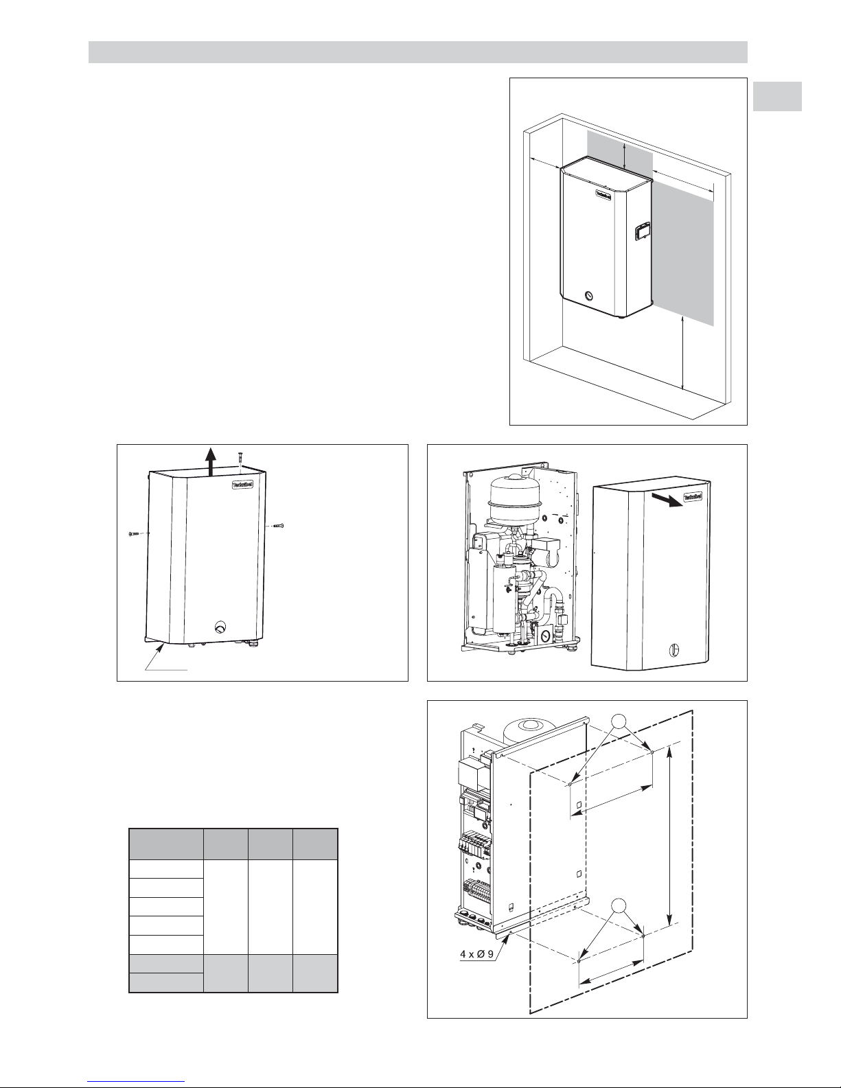
3.1 - LOCATION
• Protection index of the unit: IP 21.
•
Select the location for the unit on the basis of the following criteria
:
- the unit must be installed in a sheltered location,
- the unit must not be installed near the following:
. sources of heat,
. combustible materials,
. return / air intake of an adjacent building.
- it is necessary to make sure that the free space around the unit is
provided (see the minimum dimensions on the drawing opposite),
- installation must be simple and make maintenance work easy,
- the unit must be secured to a wall able to support its weight.
3.2 - MOUNTING THE UNIT
• Remove the cover from the unit:
- remove the retaining screws (1 on each side and 1 on top) (1).
• Slide the cover upward (2), until the bottom edge of the covers is aligned
with the lower part of the rear support, then pull it towards you (3).
• Secure the unit to the wall. Refer to the position of the 4
mounting holes in the diagram opposite.
Use anchors and screws (not included) that are adapted
to the weight of the unit and the type of wall.
- Install the 2 screws in place in the upper holes (A) in
the wall.
- Hook the unit in place.
- Install the 2 screws in place in the lower holes (B).
0.80 m
0.20 m
0.20 m
1 m
3
A
B
Z
X
Y
Minimum clearance in front of the unit: 1 m
1
1
1
2
Align the bottom edge of the cover with the
lower part of the rear support
GB
X (mm) Y (mm) Z (mm)
HKE 189R
460 360 800
HKE 259R
HKE 369R
HKE 489R
HKE 609R
HKE 709R
520 420 900
HKE 909R
Page 8

8
GB
• Replacing the cover.
- Present the cover on the unit while aligning the lower
edge with the lower part of the rear support.
- Fit the cover against the rear support to engage the
hooks in the notches (1).
- Slide the cover downward fully into place (2).
- Replace the retaining screws.
. Note: the screw (T) on top of the unit ensures the
cover's ground continuity. This is a special screw
and only this model should be used.
. The screw on the left-hand side is used primarily
for transport. In the case of insufficient clearance
(too close to a wall), this screw need not be
replaced.
3.3 - CONTROL UNIT INSTALLATION
• As the control unit is equipped with a temperature sensor, it must be
installed in a location that is representative of the temperature in zone 1.
• Note: For 2-zone applications, an ambient temperature sensor (zone 1)
(accessory) can be connected on the 2-zone module thus doing away
with the need to install the control unit in zone 1.
• Wall mounting: the unit must not be installed in corners, on shelves or
behind curtains, near sources or heat or directly exposed to sunlight. The
unit should be installed approximately 1.5 m above the floor.
• Open the box by removing the lower screw and secure the base to the
wall (mounting holes, item (1)).
• Open the protective cover (screw (2)) and connect the
BUS link to the control board (see diagram in paragraph
4.3.4.).
• Fit the control unit back on its base.
3.4 - INSTALLATION OF THE OUTDOOR
TEMPERATURE SENSOR
•
This sensor must be located outside in a location that is
representative of the temperature to be measured (on a wall
facing North / North-west) and located away from parasitic
heat sources (chimney, thermal bridge, etc..) and sheltered
from inclement weather (under a roof overhand, for
example).
• Connection as per paragraph 4.3.4.
1
2
T
Bottom of cover
Lower part of
the rear
support
Align
1
2
Base
Rear view
1.50 m
Control unit
Mini. 20 cm
Page 9

9
GB
4 - CONNECTIONS
4.1 - REFRIGERATION CONNECTIONS
Outdoor unit
Indoor unit
Gas line
Liquid line
• For the connecting pipes, use the flare nuts provided with the unit or nuts intended for the R 410 A.
• Connect the units with the connecting tubes in accordance with the table below.
R 410 A
• R 410 A is a high-pressure refrigerant (+ 50% in relation to
R 22 and R 407 C).
• The compressors approved for operation with this fluid are
filled beforehand with polyalcohol oil.
Contrary to mineral oil, it is very hygroscopic: it absorbs the
humidity of the ambient air very quickly. This can modify its
lubricant properties and lead in time to the destruction of the
compressor.
MAINTENANCE INSTRUCTIONS
1 - Never add oil to the appliance; the compressor is filled
with polyalcohol oil, a special oil which cannot tolerate the
presence of other oils.
2 - The instruments used for:
- filling,
- pressure measurements,
- emptying under vacuum,
- recovering the fluid,
must be compatible and only used for the R 410 A fluid.
Note: the pressure taps of the refrigerating circuit are
5/16 SAE (1/2 - 20 - UNF).
3 - In the case of a new charge:
- the charge must be undertaken in liquid phase,
- use a balance and a dip pipe type R 410 A cylinder,
- charge the weight of R 410 A as per the value indicated
on the unit’s identification plate (for “split systems”, refer
to the installation instructions as the charge must
consider the length of the connecting lines).
4 - In case of leakage, do not complete the charge: recover
the remaining refrigerant for recycling and perform a total
charge.
Recovery, recycling or the destruction of the fluid must be
done in compliance with the laws in force in the country
concerned.
5 - If the refrigerant circuit is opened, you must:
- avoid the entry of air into the circuit as much as
possible,
- replace or install a drier,
- perform the “vacuum operation” at a minimum level of
0.3 mbar (static).
6 - Do not release R 410 A fluid into the atmosphere. This
fluid is a fluorinated greenhouse gases, covered by the
Kyoto Protocol with a Global Warming Potential (GWP) =
1975 - (CE Directive 842 / 2006).
APPLIANCES FILLED WITH R 410 A
Model 189R Model 259R Model 369R Model 489R Model 609R Model 709R Model 909R
ø Liquid tube
1/4”
(6.35 mm)
3/8”
(9.52 mm)
3/8”
(9.52 mm)
3/8”
(9.52 mm)
3/8”
(9.52 mm)
3/8”
(9.52 mm)
1/2”
(12.7 mm)
ø Gas tube
1/2”
(12.7 mm)
5/8”
(15.88 mm)
5/8”
(15.88 mm)
5/8”
(15.88 mm)
5/8”
(15.88 mm)
3/4”
(19.05 mm)
3/4”
(19.05 mm)
Minimum pipe length 3 m 3 m 3 m 3 m 3 m 5 m 5 m
Maximum pipe length without
addition of refrigerant load
10 m 10 m 10 m 10 m 10 m 10 m 10 m
Maximum pipe length with addition
of refrigerant load
30 m 30 m 30 m 30 m 30 m 30 m 30 m
Additional load per meter 20 g 40 g 40 g 40 g 40 g 40 g 80 g
Page 10

10
GB
• For the following information:
- Maximum height between units.
- Required tools.
- Advice concerning the piping installation.
- Connection to the outdoor unit.
- Leak testing.
- Vacuum operation.
- Additional refrigerant charge.
Refer to the installation instructions provided with the outdoor unit.
• For the connection to the indoor unit's flare couplings, use 2 wrenches to
maintain the coupling.
Tighten to the following tightening torque values:
- ø 1/4”: 14 - 18 N.m.
- ø 3/8”: 34 - 42 N.m.
- ø 1/2”: 49 - 61 N.m.
- ø 5/8”: 68 - 82 N.m.
- ø 3/4”: 100 - 120 N.m.
4.2 - HYDRAULIC CONNECTION
4.2.1 - WATER INLET AND OUTLET CONNECTION
• Connect the w ater inlet and outlet lines to the corresponding
couplings.
• Install the hydraulic filter (1) (supplied) on the water intake. Connect it
using 2 isolation valves (2) (not supplied) for cleaning purposes.
• "Water connection hose" accessories may be used (refer to the
accessories paragraph).
4.2.2 - FILLING / DRAINAGE CONNECTION
• A coupling is available for filling or draining water from the unit.
• To use this connection, install a shut-off valve with drain tap (3) (not
supplied).
4.2.3 - SAFETY VALVE CONNECTION
• The unit is equipped with a safety valve that opens if the pressure in
the hydraulic system exceeds 3 bar.
A flexible hose (4) (not supplied) can be connected to the coupling
insert (coupling OD: 18 mm).
• Note: use the safety valve tap to complete the draining of the unit.
4.3 - ELECTRICAL CONNECTION
4.3.1 - GENERAL:
• The acceptable voltage variation is: ± 10% during operation.
• The electrical connection conduits must be fixed.
• Use the cable clamps underneath the unit and route the wires into the electric panel, to the terminal strips.
• Class 1 unit.
• The electrical installation must comply with the standards and regulations applicable where the unit is being installed (in
particular NF C 15-100 ≈ IEC 364).
4.3.2 - POWER SUPPLY
• The power supply must come from an isolation and electric protection device (not supplied) in accordance with existing
regulations.
• A two-pole circuit breaker (not supplied) must be installed to protect single-phase equipment or a three-pole circuit
breaker (not supplied) for three-phase equipment. See the intensity ratings table.
Note 1
:
The unit is designed to be connected to a power supply having a TT neutral regime (neutral to ground) or TN.S regime
(to neutral) as per NF C 15-100.
1
2
3
4
Page 11
11
GB
POWER SUPPLY CABLE
- Section: see amperage table.
- The sections are given as an indication only. They have to be verified and adapted, if necessary, according to the
installation conditions and the standards in force.
CURRENTS AND CROSS-SECTIONS
(*) With 6 kW electric heating module only.
SELECTION OF ELECTRIC HEATING MODULE POWERS
- To obtain the maximum electric heating module power ratings, the jumper must be installed between 22 and 23 on
terminal strip XA (jumper included).
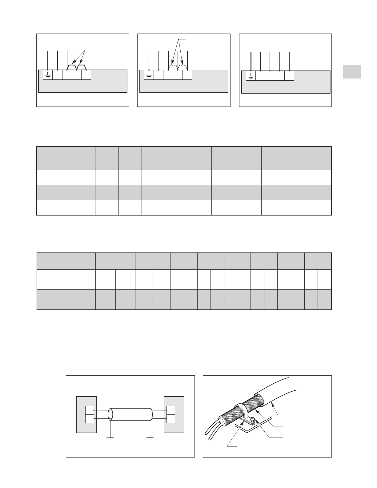
4.3.3 - CONNECTION WITH THE OUTDOOR UNIT
- The control connection between the indoor unit and the outdoor unit is made by a shielded 0.75 mm2cable
(AWG #18), with the shielding grounded at both the indoor unit and outdoor unit side.
- Maximum length 70 meters.
- The cable's shielding must be grounded at both ends by means of a metal clamp (not supplied) screwed onto the
terminal strip support plate.
- To avoid problems related to electromagnetic disturbances, do not route this cable near power cables.
1
2
U1
U2
Outdoor Unit Indoor Unit
Interconnect cable
between the indoor
unit and the outdoor
unit
Shielding
Screws (not supplied)
Metal clamp (not supplied) screwed to
the terminal strip's support plate
Grounding of the
cable shielding:
SPW-W706/906
N L1 L2 L3
Single-phase power supply
400V / 3+N+T / 50Hz
PE N
Ph1 Ph2 Ph3
Terminal
strip XA
SPW-W186/256/366/486/606
N L1 L2 L3
Single-phase power supply
230V / 1+T / 50Hz
PE N Ph
Jumper
Terminal
strip XA
SPW-W366/486/606
N L1 L2 L3
PE N Ph
Remove the
jumper
Terminal
strip XA
Model
SPWW186
230/1/50
SPW-
W256
230/1/50
SPWW366
230/1/50
SPWW366
400/3N/50
SPWW486
230/1/50
SPWW486
400/3N/50
SPWW606
230/1/50 (*)
SPWW606
400/3N/50
SPWW706
400/3N/50
SPWW906
400/3N/50
Rated input
amperage A
20.5 20.5 27 9.5 27 9.5 27 14 19 19
Protection rating A
25 25 32 12 32 12 32 16 25 25
Power supply cable
size
3G4mm23G4mm23G6mm25G2.5mm23G6mm25G2.5mm23G6mm25G2.5mm25G4mm25G4mm
2
Model
SPW-W186 SPW-W256
SPW-W366 SPW-W486
SPW-W606
single
SPW-W606
three
SPW-W706 SPW-W906
Jumper between
22 and 23 of terminal
strip XA
no yes no yes
no
yes no yes no no yes no yes no yes
Electric heating
module powers kW
3
(1.5+1.5)
4,5
(3+1.5)3(1.5+1.5)
4,5
(3+1.5)4(2+2)6(4+2)4(2+2)6(4+2)
6
only
(3+3)
6
(3+3)9(6+3)8(4+4)12(8+4)8(4+4)12(8+4)
Page 12

12
Note 2:
The sizing of the power supply cables is to be ensured by the installer in accordance with the installation conditions and
as per current standards.
Cable sizes, indicated below, are given for information purposes.
They are calculated in accordance with NFC 15-100 (≈ CEI 364) with the following hypotheses:
- Maximum current, see table below.
- Multi-pole copper cable with PR insulation.
- Installation in conduit (installation method No. 3 A / 4 A / 5 A). No other power cable.
- Ambient temperature 35°C.
Note 3
: Electromagnetic compatibility - Harmonic currents:
• The model 189R complies with the requirements of standard EN61000-3-2 defining the limits for harmonic current
emissions.
• Models 259R / 369R / 489R / 609R / 709R / 909R comply with the requirements of standard EN61000-3-12 defining the
limits for harmonic current emissions
In this case, for these models, the minimum short-circuit ratio “R
sce
” value to be respected is 250.
This value must be checked according to the characteristics of the network to which the installation is connected.
• Single-phase R
sce
=
• Three-phase R
sce
=
- Such that: Sc = Three-phase short-circuit power of the network.
Sc =
where: U
nominal
= nominal voltage between phases,
Z = impedence of the network at the main's frequency.
- Such that: Seq = Assigned apparent power of the unit,
single-phase Seq = Upx I
abs
(Up= single-phase voltage),
Three-phase Seq = x Uix I
abs(Ui
= voltage between phases).
4.3.2.1 - 230 V single-phase power supply
• Power is supplied separately on the indoor unit's power terminal. See diagram below.
Note
: consult the outdoor unit's installation manual regarding its power supply.
3
Sc
3 x Seq
Sc
Seq
U
2
nominal
Z
Power supply amperages and cable sizes
- The sections are given as an indication only. They have to be verified and adapted, if necessary, according to the
installation conditions and the standards in force.
(*) With 6 kW electric heating module power only.
HKE
N L1 L2 L3
Single-phase power supply
230 V / 1 + T / 50 Hz
N Ph
Bridge
Terminal
strip XA
Model
HKE 189R
230 / 1 / 50
HKE 259R
230 / 1 / 50
HKE 369R
230 / 1 / 50
HKE 489R
230 / 1 / 50
HKE 609R
230 / 1 / 50 (*)
Rated input
amperage (A)
20.5 27 27 27 27
Protection rating (A)
25 32 32 32 32
Power supply cable
size
3 G 4 mm
2
3 G 6 mm23 G 6 mm23 G 6 mm23 G 6 mm
2
GB
Page 13

13
1
2
U1
U2
Model
HKE
189R
HKE
259R
HKE
369R
HKE
489R
HKE
609R
single
HKE
609R
three
HKE
709R
HKE
909R
Bridge between
22 and 23 of terminal
strip XA
no yes no yes
no
yes no yes no no yes no yes no yes
Electric heating
module powers kW
3
(1.5+1.5)
4,5
(3+1.5)4(2+2)6(4+2)4(2+2)6(4+2)4(2+2)6(4+2)
6
only
(3+3)
6
(3+3)9(6+3)8(4+4)12(8+4)8(4+4)12(8+4)
Outdoor Unit Indoor Unit
Interconnect cable
between the indoor
unit and the outdoor
unit
Shielding
Screws (not supplied)
Metal clamp (not supplied) screwed
to the terminal strip's support plate
Grounding of the
cable shielding:
4.3.2.2 - 400 V three-phase power supply
• Provide a common power supply for both the outdoor unit and the indoor unit.
• The indoor unit power cable is connected to the outdoor unit's terminal strip. See diagram below.
Note
: the indoor unit's power cable must be the same size as the general power supply cable.
N L1 L2 L3
N L1 L2 L3
Single-phase power supply
400 V / 3 + N + T / 50 Hz
N Ph1 Ph2 Ph3
Remove the bridges
(for HKE 259R / 369R /
489R / 609R)
Terminal
strip XA
Terminal
strip XA
Outdoor unit GRFP
Indoor unit HKE
Power supply amperages and cable sizes
- The sections are given as an indication only. They have to be verified and adapted, if necessary, according to the
installation conditions and the standards in force.
(*) With maximum electric heating module power (see below).
4.3.2.3 - Selection of electric heating module powers
• To obtain the maximum electric heating module power ratings, the bridge must be installed between 22 and 23 on
terminal strip XA (bridge included).
Model 259R 369R 489R 609R 709R 909R
Maximum
input
amperage
(A)
Indoor unit HKE (*) 9.5 9.5 9.5 14 19 19
Outdoor unit GRFP 8.2 9 12.5 14 12.5 15
Total 17.7 18.5 22 28 31.5 34
Protection rating (A) 20 20 25 32 40 40
Power supply cable size 5 G 4 mm25 G 4 mm25 G 4 mm25 G 6 mm25 G 6 mm25 G 6 mm
2
4.3.3 - CONNECTION WITH THE OUTDOOR UNIT
• The control connection between the indoor unit and the outdoor unit is made by a shielded 0.75 mm2cable (AWG #18),
with the shielding grounded at both the indoor unit and outdoor unit side.
• Maximum length 70 meters.
• The cable's shielding must be grounded at both ends by means of a metal clamp (not supplied) screwed onto the
terminal strip support plate.
• To avoid problems related to electromagnetic disturbances, do not route this cable near power cables.
GB
Page 14

14
4.3.4 - OTHER CONTROL CONNECTIONS
Caution:
To avoid problems related to electromagnetic disturbances, do not route these cables near power cables.
B
D
C
A
A1
A2
CC1
Control unit
With built-in ambient temperature sensor.
To be installed in zone 1.
Load shedding
(if installed)
Outside air
temperature
Outdoor unit
Installation
water outlet
temperature
Installation
water return
temperature
A) BUS
- 2-conductor shielded cable, minimum size 1 mm2with shielding grounded on indoor unit side (*).
- Total length of the BUS connection: 40 meters (indoor unit / control box connection + indoor unit / 2-zone module
connection, if any or possible DHW tank).
- To be connected to the (+) and (-) terminals if terminal strip XB.
(*) Refer to the ground shielding principle in paragraph 4.3.3.
B) Outside temperature sensor
- 2-conductor cable, min. size 0.5 mm
2
.
- Maximum length 25 meters.
- To be connected to the heating board A1.
- Note:
This sensor must be located outside in a location that is representative of the temperature to be measured (on a wall facing
North / North-west) and located away from parasitic heat sources (chimney, thermal bridge, etc..) and sheltered from
inclement weather (under a roof overhand, for example)
.
C) Outdoor unit control connection
- 2-conductor shielded cable with shielding grounded on both the outdoor unit and indoor unit side.
- Minimum cable size: 0.75 mm
2
.
- Maximum length 70 meters.
- Connection as per paragraph 4.3.3.
D) Module additional heating load shedding signal (if installed)
- Two possibilities:
1) By a "remote info" signal coming from the electrical utility meter: 1 twisted pair (6/10) cable with shielding (shielding
grounded on module side).
2) By a good quality, potential-free external contact.
- Contact closed = load shedding of the additional electric heating.
- 2-conductor cable, min. size 0.5mm
2
.
- Maximum length 25 meters.
- To be connected to the heating board A1.
Indoor unit
GB
Page 15
15
GB
F) ECO signal for remote controls (if installed)
- In order to send reduced mode orders (Eco or standby) to the terminal unit remote control units in the case of
applications such as 1 terminal unit zone or 2 mixed zones.
- In the form of a potential-free contact which can used in VLV (Very Low Voltage), 2 A max.
- To be connected to the heating board A1.
- Note:
The contact can control up to 10 RCC10 (70250051) or RCC20 (70250052) type controls.
Consult the terminal unit and remote control documentation to connect this contact.
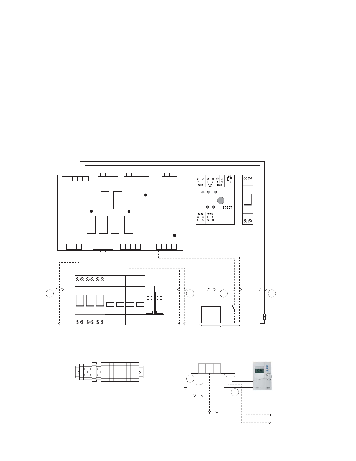
CONTROL PART CONNECTION DIAGRAM
- Route the control cables on the right side of the board.
- Pass the pilot wire (230 V) on the left side of the board.
1 2
CN1
230V
CN2 CN3 CN4
CN8 CN7 CN6 CN5
3
5 4 3 2 1 4 3 2 1 45 3 2 1 3 2 1
N U FP R1 R2 R3 C E1 E2 T+
H1A1 C A2 C4 3 2 1S1 C S2 C S3 A3 H2 H3
T- D1 D2 + -
1 2 3 4 1 2 3 4 1 2 3 4
F
D B
A
C
A1
Q4
N U
Q1
N UQ2N UQ3N U
KM1 KM2 KM3 KM4
KA1 KA2
U1 U2
1 2
R1 R2 +
E
Pilot wire
Electric
convectors
(if any)
ECO signal
(if any)
Electrical
utility
meter
Load shedding
(if installed)
Control unit
BUS connection to:
2-zone module
M2ZP or
M2ZM (if any) or
DHW tank KPECS
(if any)
OR
Outside
temperature
sensor
Heating
board
Power terminal strip XA
Control terminal strip XB
To Outdoor
Unit
Maintenance
keypad / display
unit
Page 16
16
GB
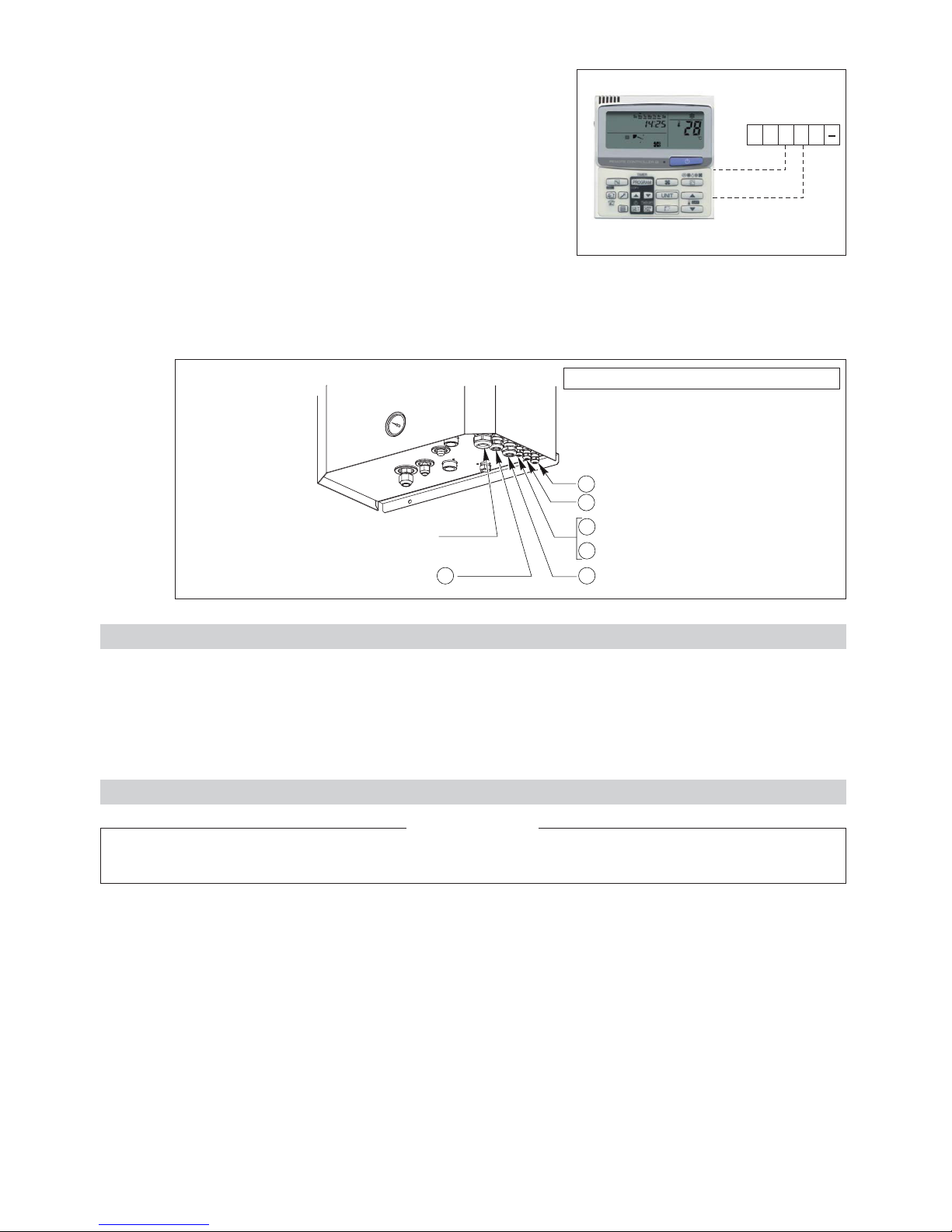
4.3.5 - MAINTENANCE KEYPAD / DISPLAY UNIT CONNECTION
• A specific keypad / display unit can be connected for maintenance
and troubleshooting operations. See maintenance manual.
Note:
This keypad / display unit must not be used for the installation's
normal operation.
4.3.6 - ROUTING OF CABLES
• To avoid problems related to electromagnetic disturbances, avoid routing control cables near power cables.
• Pass the cables through the cable glands.
• Route the control cables on the right side of the electric board.
• Pass the pilot wire (230 V), if used, on the left side of the electric board.
U1 U2 R1 R2 +
B
A
D
F
CE
Terminal XB
of the indoor unit
Black
White
BUS
Outside air temperature sensor
ECO signal for remote controls
+
Load shedding signal
Outdoor unit control connection
Pilot wire for electric convectors
Power supply
Bottom view of the indoor unit
5 - ACCESSORIES
5.1 - WATER CONNECTION HOSES
• Length 1 m, insulated, female:
- Ø 3/4” code 70600054 for HKE 189R and 259R.
- Ø 1” code 70600055 for HKE 369R, 489R and 609R.
- Ø 1”1/4 code 70600027 for HKE 709R and 909R.
6 - STARTING
Before carrying out any work on the installation, make sure that it is switched off and that access to it is prevented.
Any work must be carried out by personnel qualified and authorised to work on this type of machine.
IMPORTANT NOTE
Also refer to the installation instructions provided with the outdoor unit.
6.1 - PRELIMINARY CHECKS
6.1.1 - COOLING CIRCUIT
• Refrigeration couplings correctly tightened.
• Both of the outdoor unit's shutoff valves are open.
• integrity of the cooling circuit (per Decree of 7 May 2007).
• Also refer to the verifications indicated in the outdoor unit's installation instructions.
6.1.2 - HYDRAULIC CIRCUIT
• Hydraulic couplings correctly tightened.
• Hydraulic circuit operating correct:
- purge of circuits,
- position of valves,
- hydraulic pressure (2 bar),
• Integrity of the hydraulic circuit.
Page 17
17
GB
• Water quality:
- In order for the heat pump to operate under good conditions and provide optimum performance, it is essential to
ensure that the system’s water circuit is clean. If the water circuit becomes clogged, this will significantly affect the
machine’s performance. The circuit must therefore be cleaned with suitable products in compliance with current
standards as soon as it is installed, both for new and renovation work.
We recommend the use of products which are compatible with all metals and synthetic materials and approved by
official bodies.
Recommendations regarding water quality:
- PH: 6 to 9,
- TH: 10 to 20°F,
- Dry material in suspension: < 2 g/l,
- Granulometry: < 0.4 mm,
- Chloride: 50 mg/l maximum,
- Conductivity: 50 to 500 µS/cm2,
- Resistivity: 1 to 10 kΩ,
- Fibre: no fibres.
Any disorder which may occur on our machines due to the poor quality of the fluid in the installation will not be
covered by the warranty.
6.1.3 - ELECTRICAL SYSTEM
• The power cables are well fixed to their connection terminals. Terminals that are poorly tightened may cause overheating
and malfunctions.
• The electric cables are well insulated from any sections of sheet metal or metal parts which could damage them.
• The probe, control and power cables are properly separated.
• The machine is earthed.
6.1.4 - MISCELLANEOUS
• Overall good condition of the apparatus.
• No tools or other foreign objects inside the apparatus.
6.2 - CONFIGURATION AND PARAMETERISATION
6.2.1 - AUTO-ADDRESSING OF INDOOR AND OUTDOOR UNITS
• Set the control unit selector to “OFF”.
• Turn on the indoor and outdoor units. The unit cycles through an automatic addressing phase when the power is first
turned on. This phase may take 2 to 3 minutes and is indicated by the alternate blinking of LED1 and LED2 on the
outdoor unit card.
When these indicator lights cease blinking, addressing is completed and communication between the indoor and outdoor
unit is established.
Note 1:
The addressing phase is indicated on the screen of the keyboard / display unit (if installed) by the flashing “SETTING”
message.
Note 2:
Should a problem arise during this automatic addressing phase, a new phase can be restarted. To do this, simply
disconnect the power supply for at least 1 minute and when power is restored, press the black “AUTO ADD” button on
the outdoor unit's electronic board.
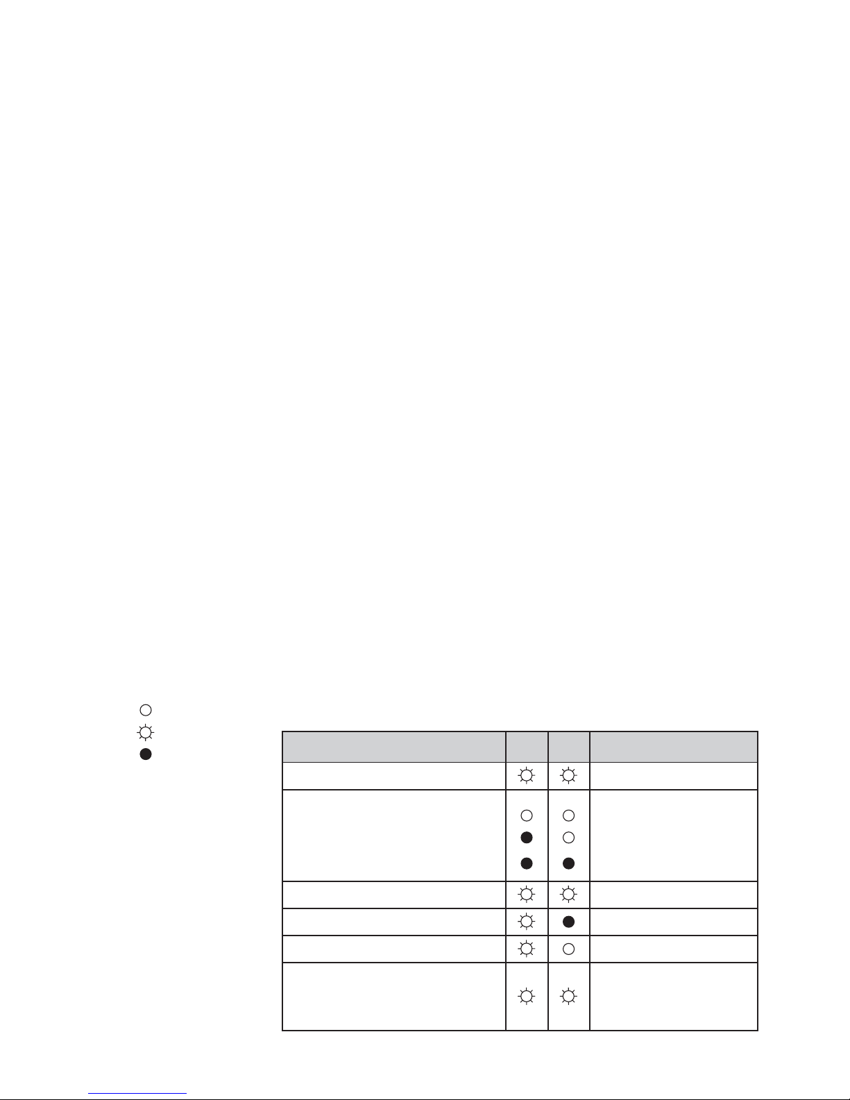
Meaning of LED1 and LED2 activity on the outdoor unit's board.
= ON steady
= ON blinking
= OFF
Meaning LED1 LED2
Auto-addressing in progress Alternating blinking
Power ON:
Step 1: no communication
Step 2: communication received from
the indoor unit
Step 3: normal communication
Alarm message Simultaneous blinking
No charge indicator
Refrigerant recovery mode
Alarms
(Refer to the details in the outdoor unit's
maintenance and troubleshooting
manual)
Repeated and alternating
blinking (of each indicator
light)
Page 18
18
GB
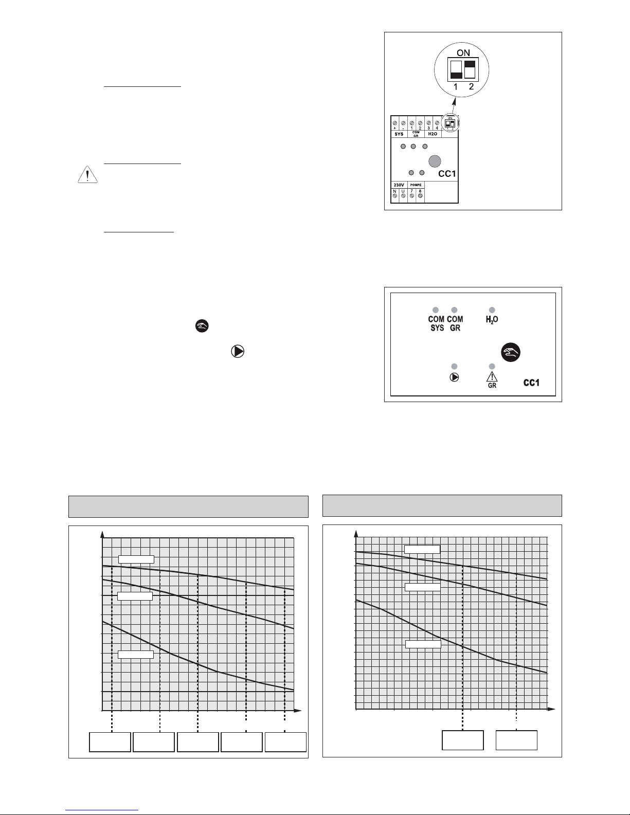
6.2.2 - MODULE CC1 CONFIGURATION
• The communication and control module manage the circulator and
the communication interface between the system and the generator.
It is equipped with 2 micro-switches, No. 1 and No. 2.
Micro-switch No. 1
:
In “ON” position, the circulator starts automatically if the outdoor
temperature is below 0°C to prevent the hydraulic circuit from
freezing. This position is recommended if the outdoor module is
installed in a location exposed to freezing temperatures (not
recommended).
The factory default setting for this micro-switch is “OFF”.
Micro-switch No. 2
:
Must be set to “ON” (activates the water flow safety on the
system).
6.2.3 - SYSTEM PARAMETERISATION
• Make sure that the control unit selector is “OFF”.
• Check the parameterisation and adapt it accordingly based on the
type of installation.
The parameters are set on the control box (refer to the system's installation manual).
6.3 - ADDITIONAL HYDRAULIC CIRCUIT VERIFICATIONS
6.3.1 - FORCED CIRCULATOR OPERATION
• In order to conduct the final verifications of the hydraulic circuit, force
the pump to start as follows (installation power ON):
- Set the system control unit to “OFF”.
- Press and hold the button for 5 seconds.
The circulator starts.
The circulator indicator light flashes.
- Check that the “H
2
O” flow indicator is illuminated.
6.3.2 - VERIFICATIONS
• Purging of circuits.
• Hydraulic pressure (2 bar).
• Water flowrate: the unit is equipped with 1/4 SAE pressure taps at the circulator inlet and outlet (see paragraph 2.1.1),
so that the pressure loss can be measured using a hydraulic pressure gauge. Use the circulator curves below to
determine the water flow rate.
In order for the apparatus to work properly, the nominal flow rate must be respected.
6.3.3 - CIRCULATOR CURVES
Micro-switches
No. 1 and No. 2
0
10
20
30
40
50
60
70
80
90
1 1.5 2 2.5 2.8
HKE 369R
1.8
HKE 259R
1.4
HKE 189R
0.9
HKE 489R
2.3
HKE 609R
2.7
HKE 189R / 259R / 369R / 489R / 609R
Circulator SXM 32-55
Water flowrate (m3/h)
Manometric delivery head (kPa) of the circulator
Speed 1
Speed 2
Speed 3
0
10
20
30
40
50
60
70
80
90
100
110
120
2 2.5 4 4.53 3.5
HKE 709R
3.4
HKE 909R
4.1
HKE 709R / 909R
Circulator SXM 32-80 OEM
Water flowrate (m3/h)
Manometric delivery head (kPa) of the circulator
Speed 1
Speed 2
Speed 3
Page 19

19
GB
7 - MAINTENANCE INSTRUCTIONS
7.1 - GENERAL MAINTENANCE
All equipment must be properly maintained in order to provide optimum performance over time. Faulty maintenance can result in
the cancellation of the product guaranty. Depending on the products, maintenance operations consist in the cleaning of filters (air,
water), internal and external exchangers, casings, and the cleaning and protection of condensate tanks. Treating odours and the
disinfection of room surfaces and volumes also contributes to the cleanliness of the air breathed by users.
• Carry out the following operations at least once a year (the frequency depends on the installation and operating conditions):
- check for leaks on the refrigerating circuit (according to the order of 7th May 2007).
- check for traces of corrosion or oil stains around the refrigerating components,
- inspect the composition and the condition of the coolant and check that it does not contain traces of refrigerating fluid,
- cleaning the exchangers,
- checking the wear parts,
- checking the operating instructions and points,
- check the safety devices,
- de-dusting the electrical equipment cabinet,
- checking that the electrical connections are secure,
- checking the earth connection,
- check the hydraulic circuit (clean the filter, water quality, purge, flowrate, pressure, etc.).
7.2 - HEATER SAFETY
• The unit's heater is equipped with an automatic-reset and a manual-reset safety thermostat.
• These thermostats trip in case of excessive temperature on the heater wall.
• Possible causes:
- Excessively low or inexistent water flowrate.
- Improperly purged water system.
• If the manual thermostat trips, correct the fault then reset the thermostat as follows:
- T
urn off and lock out the unit.
- Remove the cover.
- The thermostats are located against the heater partition, on the front (see paragraph 2.1.1).
- Press the button in the centre of the manual thermostat.
7.3 - PROTECTION OF HEATER CIRCUITS
• The heater features three heating elements each supplied with 230 V between phases and neutral. Each of these circuits
are protected by a modular circuit breaker (Q1, Q2, Q3) located inside the electrical box.
7.4 - CONTROL CIRCUIT PROTECTION
• The indoor unit's control circuit is protected by a modular circuit breaker Q4 located next to module CC1. It is accessible
through the small window on the right-hand side of the unit (without removing the cover panel).
• Before doing any work on the installation, make sure it is switched off and all power supplies locked out.
• Also check that the capacitors are discharged.
• Any work must be carried out by personnel qualified and authorised to work on this type of machine.
• Prior to all maintenance and servicing on the refrigerating circuit, one must first shut down the unit then wait a
few minutes before installing temperature or pressure sensors. Certain equipment, such as the compressor and
piping, may reach temperatures above 100°C and high pressures may lead to serious burns.
IMPORTANT NOTE
6.3.4 - SHUTDOWN FORCED CIRCULATOR OPERATION
• Press and hold the button for 5 seconds.
The circulator stops.
The circulator indicator light and the “H
2
O” flow rate light do out.
6.4 - OPERATION
• Installation power is ON.
• Start the system in the desired operating mode using the control box button (consult the system control manual and the
control box user's guide).
Page 20
20
GB
• If tripped:
- Turn off and lock out the unit.
- Correct the fault.
- Reset the circuit breaker.
Note:
The opening of circuit breaker Q4 disconnects only the control part. In the event of maintenance / servicing, all circuits
must be disconnected by opening the main circuit breaker.
7.5 - TROUBLESHOOTING RECOMMENDATIONS
• All maintenance and servicing operations on the refrigerating circuit must be conducted in accordance with standard trade
practices and safety rules: recovery of the refrigerant, inert shielded (nitrogen) brazing, etc…
• All brazing operations must be conducted by qualified welders.
• For equipment charged with R 410 A, refer to the specific instructions in paragraph 4.1 and in the outdoor unit's manual.
• This unit is equipped with pressurised equipment, for example piping.
Use only genuine parts listed in the spare parts list for replacing defective refrigeration components.
• Pipes may only be replaced by copper tubing in compliance with standard NF EN 12735-1.
• Leak detection, in the case of pressure testing:
- Never use oxygen or dry air, as the risk of fire or explosion is present.
- Use dehydrated nitrogen or a nitrogen and refrigerant mix indicated on the manufacturer's plate.
- For units equipped with pressure gauges, the test pressure must not exceed the gauges' maximum allowable pressure
rating.
• All part replacement with other than genuine parts, all modifications of the refrigerating circuit, all replacement of refrigerant
by a fluid other than that indicated on the manufacturer's plate, all use of the unit outside the application limits defined in the
documentation, shall result in the cancellation of PED EC marking compliance which shall fall under the liability of the
individual who carried out these modifications.
• The technical information, relative to the safety requirements of the various applicable directives, is indicated on the
manufacturer's plate of the unit and mentioned on the 1
st
page of this manual.
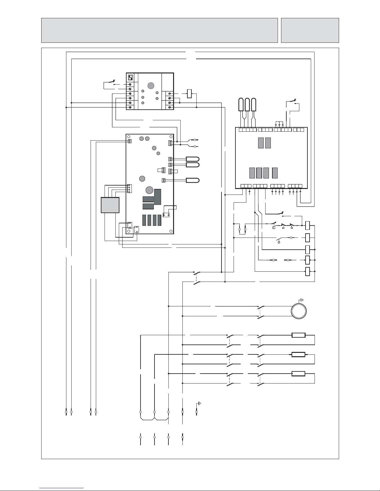
8 - WIRING DIAGRAM
A1 Heating control PCB
A2 Indoor unit PCB
CC1 Communication and control module
E1 Water pressostat
F1 Automatic - heater safety thermostat
F2 Manual - heater safety thermostat
J1 Water flow switch
KA1 Heater fault relay
KA2 Water flow relay
KM1 R1 contactor
KM2 R2 contactor
KM3 R3 contactor
KM4 M1 contactor
M1 Water circulator pump
Q1 R1 circuit breaker
Q2 R2 circuit breaker
Q3 R3 circuit breaker
Q4 Control circuit breaker
R1 Support heating element
R2 Support heating element
R3 Support heating element
S1 Water inlet temperature sensor (system)
S2 Water outlet temperature sensor
S3 Outdoor air temperature sensor
S4 Heat pump exchanger temperature sensor (E2)
S5 Liquid line temperature sensor (E1)
S6 Water return temperature sensor (Heat pump) (TA)
TR Indoor unit board power supply transformer
Symbols of the components
BU Blue
BK Black
PK Pink
RD Red
WT White
Colours of the wires
Page 21
21
GB
RD +
WH -
4
2
R2
WH-R2
BK-R1
5
L1
L2
L3
1
RD +
WH -
L4
BU - 4
L5
BU - 5
L6
BU - 6
BU
L1
2 1 - +
7
8
N U
R1
N
XA
L1
XA
L2
XA
L3
XA
3
7
6
CN80/PNL
TC/E2
CN041/RC
TA
AC IN / CN067
OC
CN040
TRANS-P
TRANS - S
CN076
T20
TCJ/E1
CN30/FS
BU
BU-1
BU-1
BU-1
1
1
R3
A1
A2
KM1
N U
CN8 CN7 CN6 CN5
CN1 CN2 CN3 CN4
5 4 3 2 1 4 13 2 12 3 435 2 1
1 2 3 1 2 3 4 1 2 3 4 21 3 4
S1 CC S2 S3 24 3 1 A1 CC A2
FP R1 R2 R3 C +D1 D2 -
A3 H1 H2 H3
E1 E2 T+ T-
230V
A1
A2
KM2
A1
A2
KM3
A1
A2
KA1
R3
Q4
1
2
3
4
KM3
Q3Q2Q1
KM2
PE
XA
F1
CX6
F2
E1
CX5/4 CX3/2
P
BUS
CX1
A1
A2
KA2
S1
S2
S3
11
KA1
12
14
J1
11
KA2
12
14
S4
S5
S6
TR
A1
M1
1
2
3
4
KM4
A2
A1
A2
KM4
U1
XBU2XB
PK-U1
L3
L2
-
XB
+
XB
L1
IU PCB
CC1
230V
POMPE
SYS
COM
GR
9
8
H2O
4 3
21
KA2
2224
R1
R2
N
XA
L1
XA
L2
XA
L3
XA
1
2
3
4
1
2
3
4
KM1
23
XA
22
XA
19
XA
20
XA21XA
BU-U2
ON
1
2
R2
1
R1
XB
R2
XB
ELECTRICAL DIAGRAM - HKE 189R / 259R / 369R / 489R / 609R /
709R / 909R - 230 / 1 / 50 - 400 / 3 N / 50
10 05 855 - 00
Power supply 400 / 3 N / 50 Hz
System
Outdoor
unit
230 / 1 / 50 Hz
Pilot
Eco
Inlet
Téléinfo
Load
shedding
Page 22

22
o18
310
13
27.5
(13)
(23.5)
336
285
608
85
(97)
46 100
12
50
5050
15
569
70790
249 32046
60
13
18
20
20
380
10
110660170
13
219 75 75105
26
290
940
780
18
20
942
296
150
219
13 13
21
18
20 10381
410
341
1313
171 660
111
How to Install the Outdoor Unit
Installing the Outdoor Unit
,esabehtekamotlairetamralimisaroetercnocesU
and ensure good drainage.
afI.eromromc5fothgiehesabaerusne,yliranidrO
drain pipe is used, or for use in cold-weather regions,
ensure a height of 15 cm or more at the feet on both
sides of the unit. (In this case, leave clearance below
the unit for the drain pipe, and to prevent freezing of
drainage water in cold weather regions.)
tlobrohcnaehtrof4-,3-,2-,1-41-1.giFotrefeR
dimensions.
.)01M(stlobrohcnahtiwteefehtrohcnaoteruseB
In addition, use anchoring washers on the top side.
(Use large square 32 ~ 32 SUS washers with JIS
nominal diameter of 10.) (Field supply)
Fig. 1-14-2
Fig. 1-14-1
Fig. 1-14-4
4- ø12 Anchor bolt hole
(Anchor bolt M8)
Air Intake
Air discharge
Drain port
For 2 HP unit
For 3 HP unit,259 (single-phase)
For 4, and 6 HP unit
Air
Intake
Drain port
Air
discharge
Piping direction
Drain port (2 locations)
Drain port
Anchor bolt (M10)
Drain port
Anchor bolt (M10)
4-R6.5 Anchor bolt hole
Air Intake
Air
Intake
For 3 HP unit (3-phase)
940
780
50
50
0 1 1170
340
15 10
380
405
660
13
13
18
75
75
70
220
38
256
Air
Intake
Air
discharge
Air Intake
4- ø32
Drain port
Anchor bolt (M10)
Fig. 1-14-3
=H 0331
Page 23

1
23
Electrical Wiring
General Precautions on Wiring
as shown on its nameplate, then carry out the
wiring closely following the wiring diagram.
(2) Provide a power outlet to be used exclusively for
each unit, and a power supply disconnect and
circuit breaker for overcurrent protection should be
provided in the exclusive line.
(3) To prevent possible hazards from insulation failure,
the unit must be grounded.
(4) Each wiring connection must be done in accordance
with the wiring system diagram. Wrong wiring may
cause the unit to misoperate or become damaged.
(5) Do not allow wiring to touch the refrigerant tubing,
compressor, or any moving parts of the fan.
(6) Unauthorized changes in the internal wiring can be
very dangerous. The manufacturer will accept no
responsibility for any damage or misoperation that
occurs as a result of such unauthorized changes.
(7) Regulations on wire diameters dier from locality to
LOCAL ELECTRICAL CODES before beginning.
You must ensure that installation complies with all
relevant rules and regulations.
(8) To prevent malfunction of the air conditioner caused
by electrical noise, care must be taken when wiring
as follows:
The remote control wiring and the inter-unit control
wiring should be wired apart from the inter-unit
power wiring.
Use shielded wires for inter-unit control wiring
between units and ground the shield on both sides.
(9) If the power supply cord of this appliance is damaged,
it must be replaced by a repair shop appointed by
the manufacture, because special-purpose tools are
required.
Recommended Wire Length and Wire Diameter for Power Supply System
Outdoor unit (Single-Phase)
(A) Power supply Tim
e delay
fuse or circuit
cap
acity
Wire size
Max. length
SPW-C186VEH 2.5 mm
2
19 m 16 A
SPW-C256VEH 2.5 mm
2
14 m 20 A
SPW-C366VEH (N) 2.5 mm
2
14 m 20 A
SPW-C486VEH (N) 4 mm
2
16 m 25 A
SPW-C606VEH (N) 6 mm
2
21 m 30 A
Outdoor unit (3-Phase)
(A) Power supply Tim
e delay
fuse or circuit
cap
acity
Wire size
Max. length
SPW-C256VEH8 2.5 mm
2
58 m 16 A
SPW-C366VEH8 2.5 mm
2
44 m 16 A
SPW-C486VEH8 2.5 mm
2
32 m 16 A
SPW-C606VEH8 2.5 mm
2
28 m 20 A
Page 24

24
Page 25

25
Page 26

26
Page 27

polarenergi.no
P.boks 117, 9450 Hamnvik
 Loading...