

Technibel GR9FI42R5I SERIES, GR9FI50R5I SERIES, GR9FI110R5I series, GR9FI80R5I series Installation Instructions Manual
Page 1

EG
I
F
D
E
INSTALLATION INSTRUCTIONS •
ISTRUZIONI D’INSTALLAZIONE
NOTICE D’INSTALLATION •
INSTALLATIONSANLEITUNGEN
INSTRUCCIONES DE INSTALACION
37.4255.084.04 07/2016
Split air conditioner system •
Condizionatore d’aria split system
Climatiseurs split •
Split-klimagerät
Acondicionador de aire de consola partida sistema split
GR9FI42R5I-GR9FI50R5I--
Page 2

2
IMPORTANT!
Please read before installation
This air conditioning system meets strict safety and operating
standards.
For the installer or service person, it is important to install or
service the system so that it operates safely and efficiently.
For safe installation and trouble-free operation, you must:
• Carefully read this instruction booklet before beginning.
• Follow each installation or repair step exactly as shown.
• Observe all local, state and national electrical codes.
• Pay close attention to all warning and caution notices given in
this manual.
•The unit must be supplied with a dedicated electrical line.
This symbol refers to a hazard or unsafe practice which can result
in severe personal injury or death.
This symbol refers to a hazard or unsafe practice which can result
in personal injury or product or property damage.
If necessary, get help
These instructions are all you need for most installation sites and
maintenance conditions.
If you require help for a special problem, contact our sale/service
outlet or your certified dealer for additional instructions.
In case of improper installation
The manufacturer shall in no way be responsible for improper
installation or maintenance service, including failure to follow the
instructions in this document.
SPECIAL PRECAUTIONS
• During installation, connect before the refrigerant system and
then the wiring one; proceed in the reverse orden when removing
the units.
When wiring
ELECTRICAL SHOCK CAN CAUSE SEVERE
PERSONAL INJURYOR DEATH. ONLYAQUALIFIED,
EXPERIENCED ELECTRICIANS SHOULD ATTEMPT
TO WIRE THIS SYSTEM.
• Do not supply power to the unit until all wiring and tubing are
completed or reconnected and checked, to ensure the grounding.
• Highly dangerous electrical voltages are used in this system.
Carefully refer to the wiring diagram and these instructions when
wiring.
Improper connections and inadequate grounding can cause
accidental injury and death.
• Ground the unit following local electrical codes.
• The Yellow/Green wire cannot be used for any connection
different from the ground connection.
• Connect all wiring tightly. Loose wiring may cause overheating
at connection points and a possible fire hazard.
• Do not allow wiring to touch the refrigerant tubing, compressor,
or any moving parts of the fan.
• Do not use multi-core cable when wiring the power supply and
control lines. Use separate cables for each type of line.
When transporting
Be careful when picking up and moving the indoor and outdoor
units. Get a partner to help, and bend your knees when lifting to
reduce strain on your back. Sharp edges or thin aluminium fins on
the air conditioner can cut your fingers.
When installing...
... In a ceiling or wall
Make sure the ceiling/wall is strong enough to hold the unit-weight.
It may be necessary to build a strong wooden or metal frame to
provide added support.
... In a room
Properly insulate any tubing run inside a room to prevent
"sweating", which can cause dripping and water damage to walls
and floors.
... In moist or uneven locations
Use a raised concrete base to provide a solid level foundation for
the outdoor unit.
This prevents damage and abnormal vibrations.
... In area with strong winds
Securely anchor the outdoor unit down with bolts and a metal
frame. Provide a suitable air baffle.
... In a snowy area (for heat pump-type systems)
Install the outdoor unit on a raised platform that is higher than
drifting snow. Provide snow vents.
When connecting refrigerant tubing
• Keep all tubing runs as short as possible.
• Use the flare method for connecting tubing.
• Apply refrigerant lubricant to the matching surfaces of the flare
and union tubes before connecting them; screw by hand and
then tighten the nut with a torque wrench for a leak-free
connection.
• Check carefully for leaks before starting the test run.
NOTE:
Depending on the system type, liquid and gas lines may be either
narrow or wide. Therefore, to avoid confusion, the refrigerant
tubing for your particular model is specified as narrow tube for
liquid, wide tube for gas.
When servicing
• Turn the power OFF at the main power board before opening
the unit to check or repair electrical parts and wiring.
• Keep your fingers and clothing away from any moving parts.
• Clean up the site after the work, remembering to check that no
metal scraps or bits of wiring have been left inside the unit being
serviced.
• Ventilate the room during the installation or testing the
refrigeration system; make sure that, after the installation, no gas
leaks are present, because this could produce toxic gas and
dangerous if in contact with flames or heat-sources.
WARNING
CAUTION
WARNING
EG
Page 3

3
Installation site selection
AVOID
• Heat sources, exhaust fans.
• Direct sunlight.
• Damp, humid or uneven locations.
• To make holes in areas where electrical wiring or conduits
are located.
DO
• Choose places as cool as possible and well ventilated.
• use lug bolts or equal to bolt down the unit, reducing
vibration and noise.
Provide a solid base for outdoor unit raised from the ground
level. Fix unit to base using 4 anchor bolts.
EG
10 cm
10 cm
40 cm
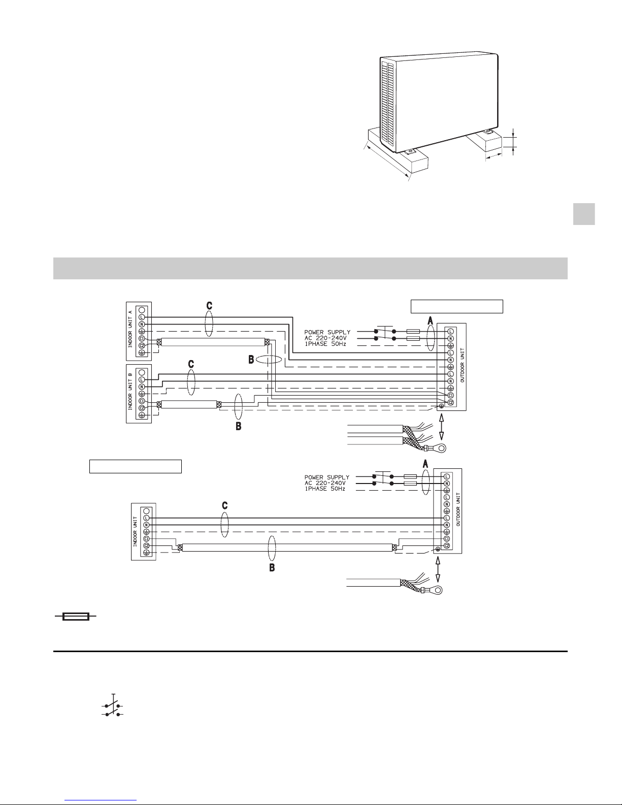
SYSTEM WIRING DIAGRAM
DUAL SPLIT
MONO SPLIT
220 - 240 V ~ 50 Hz
DELAYED FUSE
Main switch for disconnection from the supply line must have a contact separation
in all poles that provides full disconnection under category III overvoltage conditions.
Page 4

4
EG
Supply power wire A:
Multipolar electric wire. Size and length of the suggested electric wire are showed on table “electrical data”. The wire
must be Mod. H07RN-F (according to CEI 20-19 CENELEC HD 22). Make sure the length of the conductors between
the fixing point and the terminals allows the straining of the conductors L, N before that of the grounding.
Connecting wire B (SHIELDED):
Bipolar electric shielded wire; size and length of the suggested electric wire are showed on table “electrical data”.
The wires have not to be lighter than Mod. H05VVC4V5-K (according to CEI 20-20 CENELEC HD21).
Connecting wire C (with ground conductor):
Multipolar electric wire; size and length of the suggested electric wire are showed on table “electrical data”. The
wires have not to be lighter than Mod. H07RN-F (according to CEI 20-19 CENELEC HD22).
MODEL
mm
2
DUAL SPLIT
MONO SPLIT
L ("C") m
1,5150,75
≤ 25
1,5
≤ 25
L ("A") m
L ("B") m
15
≤ 20
≤ 20
10 A
LENGTH, SIZE WIRES AND DELAYED FUSE
ADDITIONAL MATERIAL REQUIRED FOR INSTALLATION (NOT SUPPLIED)
NARROW TUBE LARGE TUBE
MODEL (INDOOR UNIT)
OUTER DIAMETER MIN. THICKNESS OUTER DIAMETER MIN. THICKNESS
A 6,35 mm 0,8 mm 9,52 mm 0,8 mm
B - C 6,35 mm 0,8 mm 12,7 mm 0,8 mm
l
Deoxidized annealed copper tube for refrigerant tubing connecting the units of the system; it has to be insulated with foamed polyethylene
(min. thickness 8mm).
l
PVC pipe for condensate drain pipe (ø int.18mm) in length suitable to let the condensate flow into the outside drainage.
l
Anti-freeze oil for flare connections (about 30g.).
l
Electric wire: use insulated copper wires of size and length as shown at paragraph “SYSTEM WIRING DIAGRAMS”.
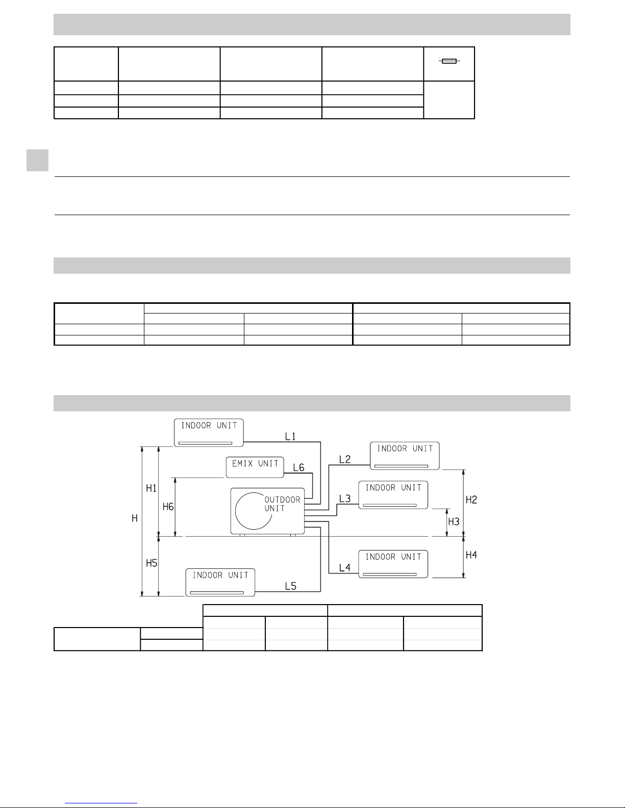
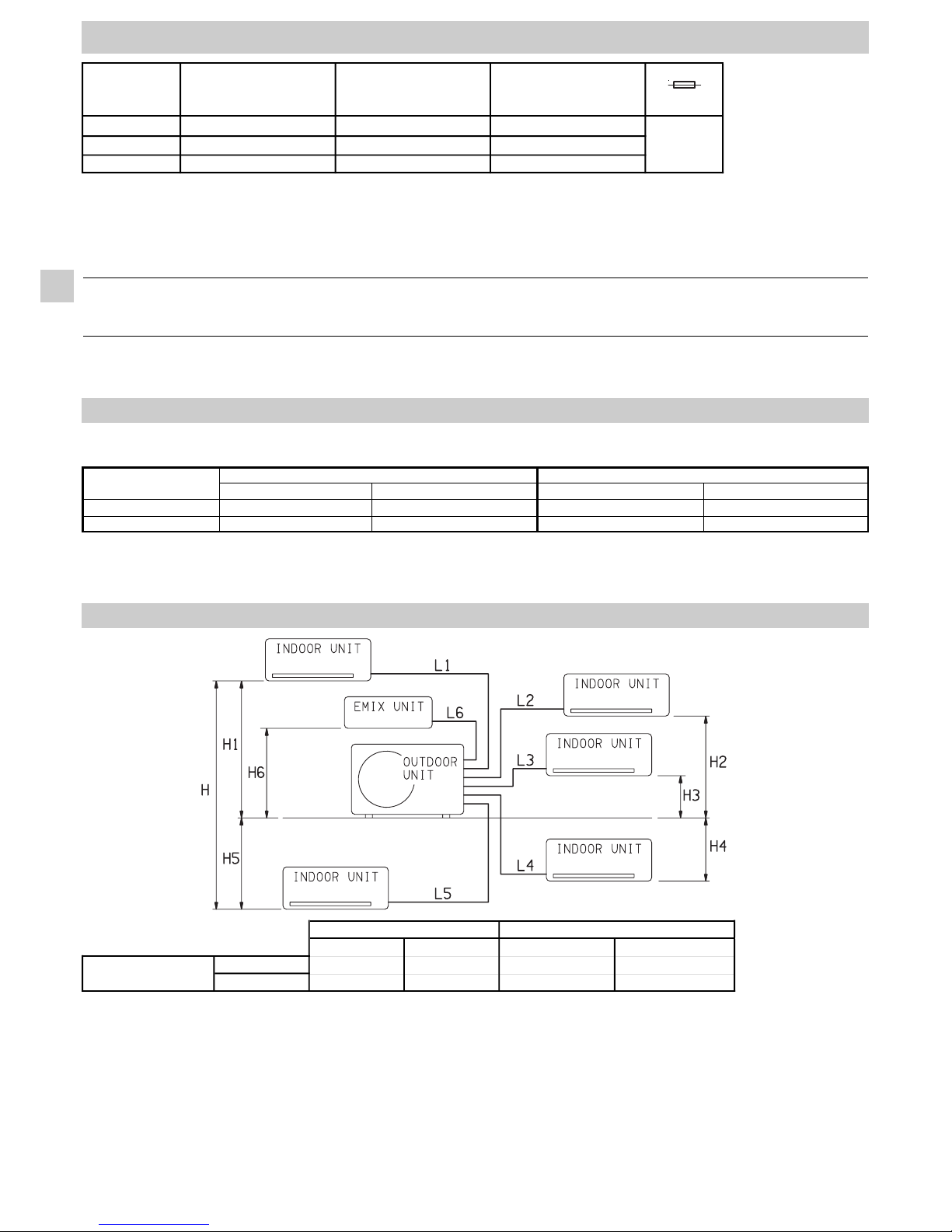
TUBING LENGTH AND ELEVATION DIFFERENCE LIMITS
L Tot. (m) L n (m) L Tot. (m) L n (m)
GR9FI42R5I--
MONO SPLIT
12 - 20 -
GR9FI50R5I-- DUAL SPLIT 15 12 30 25
AT SHIPMENT
ADDITIONAL REFRIGERANT
L Tot. = Total tubing length (L1 + L2 + L3...)
Ln = Maximum tubing length of a single indoor unit (n=1,2,3...)
REQUIRED AMOUNT OF ADDITIONAL REFRIGERANT
For tubing 1/4 “ - 3/8” = 15g/m
For tubing 1/4 “ - 1/2” = 20g/m
For tubing Emix (3/8”) = 15g/m
LIMIT OF ELEVATION DIFFERENCE - OUTDOOR UNIT/INDOOR UNIT: 10m (H1, H2, H3, H4,H5, H6)
LIMIT OF ELEVATION DIFFERENCE BETWEEN INDOOR UNITS: 5m (H)
No additional charge of compressor oil is necessary.
Page 5

5
쐽 Cooling Maximum conditions
Outdoor temperature : 43°C D.B.
Room temperature : 32°C D.B. / 23°C W.B.
쐽 Cooling Minimum conditions
Outdoor temperature : –15°C D.B.
Room temperature : 10°C D.B. / 6°C W.B.
쐽 Heating Maximum conditions
Outdoor temperature : 24°C D.B. / 18°C W.B.
Room temperature : 27°C D.B.
쐽 Heating Minimum conditions
Outdoor temperature : –15°C D.B.
Room temperature : 5°C D.B.
OPERATING LIMITS
A
B
system type
outdoor unit
Indoor unit - circuit a
Indoor unit - circuit b
A
A
B
mono split
GR9FI42R5I--
dual split
A
mono split
GR9FI50R5I--
dual split
B
C
GR9FI50R5I--
A
A
GR9FI42R5I--
Outdoor - Indoor unit combination table
Power Supply: 220 - 240 V ~ 50 Hz
A - B - C = indoor unit size
(see catalogue)
1.Standard screwdriver
2.Phillips head screwdriver
3.Knife or wire stripper
4.Tape measure
5.Level
6.Sabre saw or key hole saw
7.Hacksaw
8. Core bits ø 5
19.Hammer
10.Drill
11.Tube cutter
12.Tube flaring tool
13.Torque wrench
14.Adjustable wrench
15. Reamer (for reburring)
16.Hex. key
Tools required for installation (not supplied)
DECLARATION OF CONFORMITY
This product is marked as it satisfies Directives:
–Low voltage no. 2006/95/EC.
(Standard: EN60335-2-40:2003 (incl. Corr.:2006) + A11:2004 + A12:2005 + A13:2012
+ A1:2006 + A2:2009 con EN 60335-1:2002 + A11:2004 + A1:2004 + A12:2006 + A2:2006 + A13:2008 + A14:2010 +
A15:2011).
–Electromagnetic compatibility no. 2004/108/EC, 92/31 EEC and 93/68 EEC.
(Standard: EN55014-1 (2006) + A1(2009)
+ A2(2011), EN 55014-2 (1997) + A1(2001) + A2 (2008), EN 61000-3-2 (2006) + A1(2009) + A2(2009),
EN 61000-3-3 (2008)
–RoHS2 no.2011/65/EU.
–Regulation (EU) no. 206/2012, of 6 march 2012, concerning the specifications for ecodesign requirements of air
conditioners and fans.
–Regulation (EU) no. 626/2011, of 4 may 2011, concerning the labeling indicating the energy consumption of air
conditioners.
This declaration will become void in case of misuse and/or non observance though partial of manufacturer's installation
and/or operating instructions.
(go on page 6)
EG
REGULATION (EU) No. 517/2014 - F-GAS
The unit contains R410A, a fluorinated greenhouse gas with
a global warming potential (GWP) of 2087.50. Do not
release R410A into the atmosphere.
Page 6

2
IMPORTANTE!
Leggere prima di iniziare l’installazione
Questo sistema di condizionamento deve seguire rigidi standard
di sicurezza e di funzionamento.
Per l’installatore o il personale di assistenza è molto importante
installare o riparare il sistema di modo che quest’ultimo operi con
sicurezza ed efficienza.
Per un’installazione sicura e un buon funzionamento è
necessario:
• Leggere attentamente questo manuale di istruzioni prima di
iniziare.
• Seguire tutte le istruzioni di installazione o riparazione
esattamente come mostrato.
• Osservare tutte le norme elettriche locali, statali e nazionali.
• Fare molta attenzione a tutte le note di avvertimento e di
precauzione indicate in questo manuale.
• Per l’alimentazione dell’unità utilizzare una linea elettrica
dedicata.
Questo simbolo si riferisce a pericolo o utilizzo improprio che
possono provocare lesioni o morte.
Questo simbolo si riferisce a pericolo o utilizzo improprio che
possono provocare lesioni, danni all’apparecchio o all’abitazione.
Se necessario, chiedi aiuto
Queste istruzioni sono tutto quello che necessita per la maggior
parte delle tipologie di installazione e manutenzione.
Nel caso in cui servisse aiuto per un particolare problema,
contattare i nostri punti di vendita/assistenza o il vostro negoziante
per ulteriori informazioni.
In caso di installazione errata
La ditta non è responsabile di un’errata installazione o
manutenzione qualora non vengano rispettate le istruzioni di
questo manuale.
PARTICOLARI PRECAUZIONI
• Durante l’installazione eseguire prima il collegamento del circuito
frigorifero e poi quello elettrico, procedere in modo inverso nel
caso di rimozione delle unità.
Quando è elettrico
LA SCARICA ELETTRICA PUÒ CAUSARE LESIONI
MOLTO GRAVI O LA MORTE. SOLO ELETTRICISTI
QUALIFICATI ED ESPER TI POSSONO MANIPOLARE
IL SISTEMA ELETTRICO.
• Non alimentare l’unità finché tutti i cavi e i tubi non siano
completati o ricollegati e controllati, per assicurare le messa a
terra.
• In questo circuito elettrico vengono utilizzati voltaggi elettrici
altamente pericolosi. Fare riferimento allo schema elettrico e a
queste istruzioni durante il collegamento.
Collegamenti impropri e inadeguata messa a terra possono
causare lesioni accidentali o la morte.
• Eseguire la messa a terra dell’unità secondo le norme
elettriche locali.
• Il conduttore giallo/verde non può essere utilizzato per
collegamenti diversi dalla messa a terra.
• Fissare bene i cavi. Collegamenti inadeguati possono causare
surriscaldamento e un possibile incendio.
• I cavi elettrici non devono venire a contatto con i tubi refrigeranti,
il compressore o le parti mobili del ventilatore.
• Nel collegare l’alimentazione e le linee di controllo, non usare
cavi a più conduttori. Usare cavi separati per ciascun tipo di
linea.
Durante il trasporto
Fare attenzione nel sollevare e nello spostare le unità interna ed
esterna. È consigliabile farsi aiutare da qualcuno e piegare le
ginocchia quando si solleva per evitare strappi alla schiena. Bordi
affilati o sottili fogli di alluminio del condizionatore potrebbero
procurarvi dei tagli alle dita.
Durante l’installazione...
... A soffitto, a muro o a pavimento
Assicurarsi che siano abbastanza resistenti da reggere il peso
dell’unità. Potrebbe essere necessario costruire un telaio in legno
o metallo per provvedere a un supporto maggiore.
... In un locale
Isolare accuratamente ogni tubazione nel locale per prevenire
formazione di condensa che potrebbe causare gocciolamento e,
di conseguenza, arrecare danni a muri e pavimenti.
... In luoghi umidi o irregolari
Usare una base solida e rialzata dal terreno per predisporre l’Unità
Esterna.
Questo eviterà danni e vibrazioni anormali.
... In luoghi altamente ventilati
Ancorare saldamente l’unità esterna con bulloni e un telaio in
metallo. Provvedere a un adatto deflettore per l’aria.
... In luoghi soggetti a nevicate (per i condizionatori pompa
calore)
Installare l’Unità Esterna su una piattaforma più alta del livello di
accumulo della neve. Provvedere a un’apertura di sfogo per la neve.
Collegando il circuito frigorifero
• Tenere le tubazioni più corte possibili.
• Usare il metodo di cartellatura per collegare i tubi.
• Oliare con olio anticongelante le superfici di contatto della
cartellatura e avvitare con le mani, quindi stringere le connessioni
utilizzando una chiave dinamometrica in modo da ottenere un
collegamento a buona tenuta.
• Verificare attentamente l’esistenza di eventuali perdite prima
della prova di funzionamento (test run).
NOTA:
Asecondo del tipo di sistema, le tubazioni per liquidi o gas possono
essere sia piccole che grandi. Per evitare confusione, parlando di
tubazione refrigerante, sarà specificato: tubo piccolo per liquido,
grande per gas.
Durante le riparazioni
• Togliere tensione (dall’interruttore generale) prima di aprire
l’unità per controllare o riparare parti elettriche.
• Tenere lontano mani e vestiti da ogni parte mobile.
• Pulire dopo aver terminato il lavoro, controllando di non aver
lasciato scarti metallici o pezzi di cavo all’interno dell’unità.
• Areare il locale durante l’installazione e la prova del circuito
refrigerante; assicurarsi inoltre che, una volta completata
l’installazione, non si verifichino perdite di gas refrigerante poiché
il contatto con fiamme o fonti di calore può essere tossico e
molto pericoloso.
AVVERTIMENTO
PRECAUZIONE
AVVERTIMENTO
GIG
Page 7

3
I
Scelta del luogo di installazione
EVITARE
• La vicinanza a fonti di calore o ad aree interessate da
espulsioni di aria calda.
• L’esposizione diretta al sole.
• Zone umide o soggette ad allagamenti e piano di appoggio
non livellato.
• Di eseguire fori nelle zone dove si trovano parti elettriche
o impianti.
È PREFERIBILE
• Scegliere aree possibilmente in ombra e leggermente
ventilate.
• Fissare l’unità alla base di appoggio per evitare vibrazioni.
Predisporre l'unità esterna su base solida rialzata dal terreno
e fissarla con 4 bulloni a espansione.
10 cm
10 cm
40 cm
COLLEGAMENTI ELETTRICI DEL SISTEMA
DUAL SPLIT
MONO SPLIT
220 - 240 V ~ 50 Hz
FUSIBILE RITARDATO
Il dispositivo di disconnessione dalla rete di alimentazione deve avere una distanza
di apertura dei contatti che consenta la disconnessione completa nelle condizioni
della categoria di sovratensione III.
Page 8
4
GIG
Cavo di alimentazione A:
Cavo elettrico multipolare; la sezione e la lunghezza del cavo elettrico consigliato sono indicate in tabella dati elettrici. Il cavo deve
essere del tipo H07RN-F (secondo CEI 20-19 CENELEC HD22). Assicurarsi che la lunghezza dei conduttori fra il punto di fissaggio
del cavo ed i morsetti sia tale che i conduttori attivi si tendano prima del conduttore di messa a terra.
Cavo di collegamento B (SCHERMATO):
Cavo elettrico bipolare schermato; la sezione e la lunghezza del cavo elettrico consigliato sono indicate in tabella
dati elettrici. Il cavo non deve essere più leggero del tipo H05VVC4V5-K (secondo CEI 20-20 CENELEC HD21).
Cavo di collegamento C (con conduttore di terra):
Cavo elettrico multipolare; la sezione e la lunghezza del cavo elettrico consigliato sono indicate in tabella dati elettrici. Il cavo non
deve essere più leggero del tipo H07RN-F (secondo CEI 20-19 CENELEC HD22).
MODEL
mm
2
DUAL SPLIT
MONO SPLIT
L ("C") m
1,5150,75
≤ 25
1,5
≤ 25
L ("A") m
L ("B") m
15
≤ 20
≤ 20
10 A
LUNGHEZZA, SEZIONE CAVI E FUSIBILI RITARDATI
MATERIALE ADDIZIONALE PER L'INSTALLAZIONE (NON FORNITO)
TUBO PICCOLO TUBO GRANDE
MODELLO (UNITA’ INT.)
DIAMETRO ESTERNO SPESSORE MINIMO DIAMETRO ESTERNO SPESSORE MINIMO
A
6,35 mm 0,8 mm 9,52 mm 0,8 mm
B - C
6,35 mm 0,8 mm 12,7 mm 0,8 mm
l
Tubo in rame ricotto e disossidato per refrigerazione per il collegamento tra le unità, ed isolato con polietilene espanso di spessore min.
8 mm.
l
Tubo in PVC per scarico condensa (ø int. 18 mm) di lunghezza sufficiente a convogliare la condensa ad uno scarico esterno.
l
Olio refrigerante per connessioni a cartella (circa 30 g.)
l
Cavo elettrico: utilizzare cavi di rame isolato del tipo, sezione e lunghezza indicati nel paragrafo “COLLEGAMENTI ELETTRICI DEL SISTEMA”
.
LIMITI SU LUNGHEZZA TUBI DI COLLEGAMENTO E DISLIVELLO
L Tot. (m) L n (m) L Tot. (m) L n (m)
GR9FI42R5I--
MONO SPLIT
12 - 20 -
GR9FI50R5I-- DUAL SPLIT 15 12 30 25
CARICA STANDARD
CARICA AGGIUNTIVA
L Tot. = Lunghezza totale delle tubazioni, data dalla somma delle tubazioni di ogni singola unità interna (L1 + L2 + L3...)
Ln = Lunghezza massima delle tubazioni della singola unità interna (n=1,2,3...)
QUANTITA’DI REFRIGERANTE AGGIUNTIVA
Per tubazioni 1/4 “ - 3/8” = 15g/m
Per tubazioni 1/4 “ - 1/2” = 20g/m
Per tubazioni Emix (3/8”) = 15g/m
MASSIMO DISLIVELLO - UNITA’ESTERNA/UNITA’ INTERNA: 10m (H1, H2, H3, H4, H5, H6)
MASSIMO DISLIVELLO TRA UNITA’ INTERNE: 5m (H)
Non è necessaria alcuna aggiunta di olio al compressore.
Page 9

5
1.Cacciavite a lama
2.Cacciavite medio a stella
3.Forbici spelafili
4.Metro
5.Livella
6.Punta fresa a tazza
7.Seghetto
8.Punta da trapano ø 5
1
9.Martello
10.Trapano
11.Tagliatubi a coltello rotante
12.Flangiatubi a giogo per
attacco a cartella
13.Chiave dinamometrica
14.Chiavi fisse o a rullino
15.Sbavatore
16.Chiave esagonale
Attrezzi necessari per l’installazione (non forniti)
쐽
Condizioni Massime in Raffreddamento
Temperatura esterna : 43°C B.S.
Temperatura internea: 32°C B.S. / 23°C B.U.
쐽
Condizioni Minime in Raffreddamento
Temperatura esterna : –15°C B.S.
Temperatura interna: 10°C B.S. / 6°C B.U.
쐽
Condizioni Massime in Riscaldamento
Temperatura esterna : 24°C B.S. / 18°C B.U.
Temperatura interna: 27°C B.S.
쐽
Condizioni Minime in Riscaldamento
Temperatura esterna : –15°C B.S.
Temperatura interna: 5°C B.S.
LIMITI DI FUNZIONAMENTO
Alimentazione elettrica:
220 - 240 V ~ 50 Hz
A
B
Tipo sistema
Unità esterna
Unità interna - circuito a
Unità interna - circuito b
mono split
GR9FI42R5I--
mono split
GR9FI50R5I--
B
C
dual split
GR9FI42R5I--
A
A
dual split
GR9FI50R5I--
AAA
B
Tabella combinazioni unità Esterna - Interna
A - B - C = taglia unità interna
(vedi catalogo)
DICHIARAZIONE DI CONFORMITÀ
Questo prodotto è marcato in quanto conforme alle Direttive:
–Bassa Tensione n. 2006/95/CE (Standard: EN60335-2-40:2003 (incl. Corr .:2006) + A11:2004 + A12:2005 + A13:2012
+ A1:2006 + A2:2009 with EN 60335-1:2002 + A11:2004 + A1:2004 + A12:2006 + A2:2006 + A13:2008 + A14:2010 +
A15:2011).
–Compatibilità Elettromagnetica n. 2004/108/CE, 92/31 CEE e 93/68 CEE. (Standard: EN55014-1 (2006) + A1(2009)
+ A2(2011), EN 55014-2 (1997) + A1(2001) + A2 (2008), EN 61000-3-2 (2006) + A1(2009) + A2(2009),
EN 61000-3-3 (2008)
–RoHS2 n.2011/65/UE.
–Regolamento (UE) n. 206/2012, del 6 marzo 2012, relativo alle specifiche per la progettazione ecocompatibile dei
condizionatori d’aria e dei ventilatori.
– Regolamento (UE) n. 626/2011, del 4 maggio 2011, relativo all’etichettatura indicante il consumo d’energia dei
condizionatori d’aria.
Questa dichiarazione sarà nulla nel caso di impiego diverso da quello dichiarato dal Fabbricante e/o di mancata
osservanza, anche solo parziale, delle istruzioni d'installazione e/o d'uso.
(
continua a pag. 6
)
I
REGOLAMENTO (UE) N. 517/2014 - F-GAS
L’unità contiene R410A, un gas fluorurato a ef fetto serra,
con potenziale di riscaldamento globale (GWP) = 2087,50.
Non disperdere R410A nell’ambiente.
Page 10
2
IMPORTANT!
Veuillez lire ce qui suit avant de commencer
Ce système de conditionnement de l'air répond à des normes
strictes de fonctionnement et de sécurité. En tant qu'installateur
ou ingénieur de maintenance, une partie importante de votre
travail est d'installer ou d'entretenir le système de manière à ce
qu'il fonctionne efficacement en toute sécurité.
Pour effectuer une installation sûre et obtenir un
fonctionnement sans problème, il vous faut:
• Lire attentivement cette brochure d'information avant de
commencer.
• Procéder à chaque étape de l'installation ou de la réparation
exactement comme il est indiqué.
• Respecter toutes les réglementations électriques locales,
régionales et nationales.
• Observer toutes les recommandations de prudence et de sécurité
données dans cette notice.
• Pour l'alimentation de l'appareil utiliser une ligne électrique
dédiée.
Ce symbole fait référence à une pratique dangereuse ou
imprudente qui peut entraîner des blessures personnelles ou la
mort.
Ce symbole fait référence à une pratique dangereuse ou
imprudente qui peut entraîner des blessures personnelles ou des
dégâts matériels, soit à l'appareil, soit aux installations.
Si nécessaire, demandez que l'on vous prête assistance
Ces instructions suffisent à la plupart des sites d'installation et
des conditions de maintenance. Si vous avez besoin d'assistance
pour résoudre un problème particulier, adressez-vous à notre
service aprés vente ou à votre revendeur agréé pour obtenir des
instructions supplémentaires.
Dans le cas d'une installation incorrecte
Le fabricant ne sera en aucun cas responsable dans le cas d'une
installation ou d'une maintenance incorrecte, y compris dans le cas
de non-respect des instructions contenues dans ce document.
PRECAUTIONS PARTICULIERES
• Pour l’installation: raccorder les liaisons frigorifiques, puis les
liaisons électriques.
Pour le démontage: procéder de manière inverse.
Lors du câblage
UNE DECHARGE ELECTRIQUE PEUT ENTRAINER UNE
BLESSURE PERSONNELLE GRAVE OU LA MORT.
SEUL UN ELECTRICIEN QUALIFIE ET EXPERIMENTE
DOIT EFFECTUER LE CABLAGE DE CE SYSTEME.
• Ne mettez pas l'appareil sous tension tant que tout le système
de câbles et de tuyaux n'est pas terminé ou rebranché et vérifié,
pour assurer la mise à la terre.
• Des tension électriques extrêmement dangereuses sont utilisées
dans ce système. Veuillez consulter attentivement le schéma de
câblage et ses instructions lors du câblage.
Des connexions incorrectes ou une mise à la terre inadéquate
peuvent entraîner des blessures accidentelles ou la mort.
• Effectuez la mise à la terre de l'appareil en respectant les
réglementations électriques locales.
• Le câble jaune/vert ne peut en aucun cas être utilisé pour toute
autre connexion que celle de la mise à la terre.
• Serrez fermement toutes les connexions. Un câble mal fixé
peut entraîner une surchauffe au point de connexion et présenter
un danger potentiel d'incendie.
• Il ne faut en aucun cas laisser les câbles toucher la tuyauterie
du réfrigérant, le compresseur ou toute pièce mobile.
• N’utilisez pas de câble multiconducteur pour le câblage des
lignes d’alimentation électrique et celles de commande. Utilisez
des câbles séparés pour chaque type de ligne.
Lors du transport
Soyez prudent lorsque vous soulevez et déplacez les appareils
intérieur et extérieur. Demandez à un collègue de vous aider, et
pliez les genoux lors du levage afin de réduire les efforts sur votre
dos. Les bords acérés ou les ailettes en aluminium mince se
trouvant sur le climatiseur risquent de vous entailler les doigts.
Lors de l'installation...
... dans un plafond ou un mur
Assurez-vous que le plafond ou le mur sont suffisamment solides
pour supporter le poids de l'appareil. Il peut être nécessaire de
construire un solide châssis en bois ou en métal pour offrir un
support supplémentaire.
... dans une pièce
Isolez correctement tout tuyau circulant à l'intérieur d'une pièce pour
éviter que de la condensation ne s'y dépose et ne goutte, ce qui
pourrait endommager les murs et les planchers.
... dans des endroits humides ou sur des surfaces irrégulières
Utilisez une plate-forme surélevée pour offrir une base solide et
régulière à l'appareil extérieur.
Ceci permettra d'éviter des dégâts causés par l'eau et des
vibrations anormales.
... dans une zone exposée à des vents forts
Ancrez solidement l'appareil extérieur avec des boulons et un
châssis en métal. Réalisez un déflecteur efficace.
... dans une zone neigeuse (pour le système du type reversible)
Installez l'appareil extérieur sur une plate-forme surélevée à un
niveau supérieur à l'amoncellement de la neige. Réalisez des
évents à neige.
Lors de la connexion des tuyaux de réfrigération
• Limitez au maximum la longueur des tuyaux.
• Les raccordements sont de type flare.
• Appliquez de l’huile frigorifique sur les surfaces de contact avant
de les connecter, puis serrez l'ecrou avec une clé
dynamométrique pour effectuer une connexion sans fuite.
• Recherchez soigneusement la présence de fuites avant
d'effectuer l'essai de fonctionnement.
NOTE:
Selon le type du système, les tuyaux de gaz et de liquide peuvent
être petits ou gros. Par conséquent, afin d'éviter toute confusion,
le tuyau de réfrigérant de votre modèle particulier est dénommé
"petit" pour le liquide et "gros" pour le gaz.
Lors de la maintenance
• Interrompre l'alimentation électrique sur le commutateur principal
avant d'ouvrir l'appareil pour vérifier ou réparer le câblage et
les pièces électriques.
• Veillez à maintenir vos doigts et vos vêtements éloignés de
toutes les pièces mobiles.
• Nettoyez le site lorsque vous avez fini, en pensant à vérifier
que vous n'avez laissé aucune ébarbure de métal ou morceau
de câble à l'intérieur de l'appareil dont vous avez effectué la
maintenance.
• Aèrez la pièce pendant l'installation et l'essai du circuit réfrigérant;
assurez-vous que, après l'installation, des fuites de gaz
réfrigérant ne se produisent pas, puisque le contact avec des
flammes ou des sources de chaleur peut être toxique et très
dangereux.
DANGER
ATTENTION
DANGER
FG
Page 11

3
GF
Choix de l'emplacement d'installation
EVITEZ
• Les sources de chaleur, les ventilateurs d'évacuation,
etc.
• La lumière directe du soleil.
• Les endroits mouillés, humides ou de surface irrégulières.
• De faire des trous où il y a des câbles électriques ou des
conduits.
RECHERCHEZ
• Un emplacement aussi frais que possible et bien ventilé.
• Utilisez des boulons ou similaire pour fixer l'appareil, afin
d'en réduire le bruit et les vibrations.
Mettre l'unité extérieure sur une base solide degagée du sol
et la fixer à l'aide de 4 faire-fond.
10 cm
10 cm
40 cm
BRANCHEMENTS ELECTRIQUES DU SYSTEME
DUAL SPLIT
MONO SPLIT
220 - 240 V ~ 50 Hz
FUSIBLE RETARDE
Le dispositif de sectionnement de la ligne doit avoir une distance d'ouverture des
contacts qui permit le sectionnement complet dans les conditionnes de la catégorie
de surtension III.
Page 12
4
FG
MATERIEL ACCESSOIRES POUR L'INSTALLATION (NON LIVRE)
PETIT TUBE GROS TUBE
MODELE (UNITE INT.)
DIAMETRE EXTERIEUR EPAISSEUR MIN. DIAMETRE EXTERIEUR EPAISSEUR MIN.
A 6,35 mm 0,8 mm 9,52 mm 0,8 mm
B - C 6,35 mm 0,8 mm 12,7 mm 0,8 mm
l
Lignes en tube cuivre recuit de qualité frigorifique pour le raccordement entre les unités. La ligne doit être isolée en mousse de
polyéthylène d’épaisseur min. de 8mm.
l
Tube en PVC pour sortie des condensat (Ø int.18mm) ayant une longueur suffisante pour diriger les condensats vers une sortie extérieure.
l
Huile frigorifique pour connexion flares (30 g. environ).
l
Câble électrique: Utiliser câbles en cuivre isolé de type, section et longeur indiquées dans le paragraphe “BRANCHEMENTS ELECTRIQUES
DU SYSTEME”.
LIMITES LONGUEUR DES LIASONS FRIGORIFIQUES ET DENIVELLATION
L Tot. (m) L n (m) L Tot. (m) L n (m)
GR9FI42R5I--
MONO SPLIT
12 - 20 -
GR9FI50R5I-- DUAL SPLIT 15 12 30 25
CHARGE STANDARD
CHARGE ADDITIONNELLE
L Tot. = longueur totale des tuyaux (L1 + L2 + L3...)
Ln =
longueur maximum des tuyaux
de chaque unité intérieure (n=1,2,3...)
QUANTITE DE REFRIGERANT ADDITIONNEL
Pour
tuyaux
1/4 “ - 3/8” = 15g/m
Pour
tuyaux
1/4 “ - 1/2” = 20g/m
Pour
tuyaux
Emix (3/8”) = 15g/m
DENIVELLATION MAXIMUM - UNITE EXTERIEURE/UNITE INTERIEURE: 10m (H1, H2, H3, H4, H5, H6)
DENIVELLATION MAXIMUM ENTRE LES UNITES INTERIEURES: 5m (H)
Il n'est pas nécessaire d’ajouter de l'huile au compresseur.
Câble d’alimentation A:
Câble électrique multipolaire: la section et la longueur du câble électrique recommandé sont indiquées dans le tableau “Données
électriques”. Le câble doit être de type H07RN-F (selon CEI 20-19 CENELEC HD22).
Assurez-vous que la longueur des conducteurs entre le point de fixation du câble et le bornier soit telle que les conducteurs
actifs (Phase - Neutre) se tendent avant le conducteur de mise à la terre (pour permettre aux conducteurs actifs Phase - Neutre
de se débrancher avant le conducteur de terre si le câble d’alimentation est tiré accidentellement).
Câble de raccordement B (BLINDE):
Câble électrique bipolaire blindé: la section et la longueur du câble électrique recommandé sont indiquées dans
le tableau “Données électriques”. Le câble doit être de type H05VVC4V5-K minimum (selon CEI 20-20 CENELEC HD21).
Câble de raccordement C (avec mise à la terre):
Câble électrique multipolaire: la section et la longueur du câble électrique recommandé sont indiquées dans le tableau “Données
électriques”. Le câble doit être de type H07RN-F minimum (selon CEI 20-19 CENELEC HD22).
MODEL
mm
2
DUAL SPLIT
MONO SPLIT
L ("C") m
1,5150,75
≤ 25
1,5
≤ 25
L ("A") m
L ("B") m
15
≤ 20
≤ 20
10 A
LONGUEUR, SECTION CABLES ET FUSIBLES RETARDES
Page 13

5
(suite page 6)
쐽 Conditions maximales en Refroidissement
Température extérieure: 43°C B.S.
Température intérieure : 32°C B.S. / 23°C B.H.
쐽 Conditions minimales en Refroidissement
Température extérieure: –15°C B.S.
Température intérieure : 10°C B.S. / 6°C B.H.
쐽 Conditions maximales en Chauffage
Température extérieure: 24°C B.S. / 18°C B.H.
Température intérieure : 27°C B.S.
쐽 Conditions minimales en Chauffage
Température extérieure: –15°C B.S.
Température intérieure : 5°C B.S.
LIMITES DE FONCTIONNEMENT
Alimentation électrique
:
220 - 240 V ~ 50 Hz
Table combinaisons unité Extérieure - Intérieure
Unité intérieure - circuit b
Unité intérieure - circuit a
A
GR9FI50R5I--
AAA
B
dual split
A
dual split
GR9FI42R5I--
mono split
GR9FI50R5I--
B
C
mono split
GR9FI42R5I--
Type sistème
Unité extérieure
A
B
A - B - C =
dimension unité intérieure
(voir le catalogue)
1.Tournevis à tête plate
2. Tournevis moyen cruciforme
3.Pince à dénuder
4.Mètre
5.Niveau
6.Scie cloche
7.Scie passe-partout
8.Foret pour perceuse ø 5
19.Marteau
10.Perceuse
11.Coupe-tubes
12.Dudgeonnière pour
connexion flares
13.Clé dynamométrique
14.Clés fixes et à molette
15.Ebarbeur
16.Clé héxagonale
Outillage necessaire à l'installation (non livré)
DECLARATION DE CONFORMITÉ
Ce produit est marqué puisque il est conforme aux Directives:
–Basse T ension n° 2006/95/CE.
(Standard: EN60335-2-40:2003 (incl. Corr.:2006) + A11:2004 + A12:2005 + A13:2012
+ A1:2006 + A2:2009 with EN 60335-1:2002 + A11:2004 + A1:2004 + A12:2006 + A2:2006 + A13:2008 + A14:2010 +
A15:2011).
–Compatibilité Electromagnétique n° 2004/108/CE, 92/31 CEE et 93/68 CEE.
(Standard: EN55014-1 (2006) + A1(2009)
+ A2(2011), EN 55014-2 (1997) + A1(2001) + A2 (2008), EN 61000-3-2 (2006) + A1(2009) + A2(2009),
EN 61000-3-3 (2008)
–RoHS2
n°
2011/65/UE.
–Regolamento (UE) n. 206/2012, del 6 marzo 2012, relativo alle specifiche per la progettazione ecocompatibile dei
condizionatori d’aria e dei ventilatori.
– Regolamento (UE) n. 626/2011, del 4 maggio 2011, relativo all’etichettatura indicante il consumo d’energia dei
condizionatori d’aria.
Questa dichiarazione sarà nulla nel caso di impiego diverso da quello dichiarato dal Fabbricante e/o di mancata
osservanza, anche solo parziale, delle istruzioni d'installazione e/o d'uso.
REGLEMENT (UE) n ° 517/2014 RELATIF AUX GAZ À
EFFET DE SERRE
L'appareil contient R410A, un gaz fluoré à effet de serre,
avec un potentiel de réchauffement global (PRG) de
2087.50. Ne déchargez pas de R410Adans l'atmosphère.
GF
Page 14

2
WICHTIG!
Bitte vor Arbeitsbeginn lesen
Diese Klimaanlage entspricht strengen Sicherheits- und
Betriebsnormen.
Für den Installateur oder Bediener dieser Anlage ist es wichtig, sie
so einzubauen oder zu warten, daß ein sicherer und effizienter
Betrieb gewährleistet wird.
Für eine sichere Installation und einen sorgenfreien Betrieb
müssen Sie:
• Diese Anleitungsbroschüre vor Arbeitsbeginn aufmerksam lesen.
• Jeden Installations- und Reparaturschritt entsprechend der
Beschreibung ausführen.
• Alle örtlichen, regionalen und landesweiten Vorschriften zum
Umgang mit Elektrizität befolgen.
• Alle Hinweise zur Warnung und Vorsicht in dieser Broschüre
aufmerksam beachten.
• Eine eigene elektrische Zuleitung für die Versorgung.
Dieses Symbol bezieht sich auf eine Gefahr oder eine falsche
Verwendung der Anlage, die starke Körperverletzungen oder Tod
verursachen können..
Dieses Symbol bezieht sich auf eine Gefahr oder eine falsche
Verwendung der Anlage, die starke Körperverletzungen oder
Sachbeschädigungen verursachen können.
Fragen Sie um Rat, wenn das notwendig ist
Diese Anleitungen sind für die meisten Einbauten und
Wartungsbedingungen ausreichend. Wenn Sie wegen eines
besonderen Problems Rat benötigen, wenden Sie bitte an unser
Verkaufs-/Wartungsbüro oder Ihren autorisierten Händler.
Im Falle unsachgemäßer Installation
Der Hersteller ist in keinem Fall für unsachgemäße Installation
und Wartung verantwortlich, wenn den Anleitungen in dieser
Broschüre nicht gefolgt werden.
BESONDERE VORSICHTSMASSNAHMEN
• Wehr
änd der Installation verbinden Sie erst die Kühlrohre, dann
die elektrischen Kabeln.
Wenn Sie die Einheit entfernen sollen, verfahren Sie umgekehrt.
Bei der Kabelverlegung
STROMSCHLÄGE KÖNNEN KÖRPERVERLETZUNGEN
UND TOD ZUR FOLGE HABEN.
DIE KABELVERLEGUNG DIESES SYSTEMS SOLLTE
NUR VON QUALIFIZIERTEN UND ERFAHRENEN
ELEKTRIKERN AUSGEFÜHRT WERDEN.
• Stelle Sie die Stromversorgung des Gerätes erst wieder her,
wenn alle Kabel und Rohre verlegt oder wiederverbunden und
überprüft sind, um die Erdung zu versichern.
• Dieses System benutzt hochgefährliche Spannungen. Beachten
Sie mit größter Aufmerksamkeit den Stromaufplan und diese
Anleitungen, wenn Sie Leitungen verlegen. Unsachgemäße
Verbindungen und unzureichende Erdung können
Unfallverletzungen oder Tod verursachen.
• Erden Sie das Gerät gemäß den örtlich zutreffenden
Vorschriften.
• Das Gelbe/Grüne Kabel ist für die ausschließliche Verwendung
als Erdleitung.
• Verbinden Sie Kabel fest miteinander. Lockere Verbindungen
können Überhitzung an den Verbindungspunkten erzeugen und
ein mögliches Feuerrisiko bedeuten.
• Stellen Sie sicher, daß die Verdrahtung nicht die Kühlmittelrohre,
den Kompressor oder die beweglichen Teile des Ventilators
berührt.
• Verwenden Sie keine Mehraderkabel für die Verdrahtung der
Stromversorgung und Steuerleitungen. Benutzen Sie separate
Kabel für jeden Leitungstyp.
T
ransport
Heben und bewegen Sie die Innenraum- und Außengeräte mit
großer Vorsicht. Lassen Sie sich von einer dritten Person helfen
und beugen Sie die Knie, um die Belastung auf den Rücken zu
verringern. Scharfe Kanten oder die dünnen Aluminiumrippen des
Klimatisierungsgerätes können Schnittwunden an den Fingern
verursachen.
Installation...
... an einer Decke oder Wand
Versichern Sie sich, daß die Decke/Wand stark genug ist, das
Gewicht des Gerätes zu tragen. Es mag notwendig sein, einen
starken Holz- oder Metallrahmen zu konstruieren, um zusätzliche
Unterstützung zu erhalten.
... in einem Raum
Isolieren Sie vollständig jede im Zimmer verlegte Röhre, um
"Schwitzen" und Tropfen zu verhindern, was zu Wasserschäden
an Wänden und Böden verursachen kann.
... an feuchten oder unebenen Stellen
Um für eine solide, ebene Unterlage für das Außengerät zu sorgen,
benutzen Sie einen erhöhten Betonsockel oder Betonsteine. Dies
verhindert Wasserschaden und ungewöhnliche Vibrationen.
... in Gebieten mt starkem Wind
Sichern Sie das Außengerät mit Bolzen und einem Metallrahmen.
Sorgen Sie für einen ausreichenden Windschutz.
... in Bereichen mit starkem Schneefall (für Wärmepumpesysteme)
Installieren Sie das Außengerät auf einer Unterlage, die höher
als mögliche Schneeverwehungen ist. Sorgen Sie für geeignete
schneesichere Durchlaßöffnungen für An- oder Abluft..
V
erlegung der Kühlrohre
• Halten Sie alle Rohrlänge so kurz wie möglich.
• Verbinden Sie die Rohre mit der Bördelmethode.
• Streichen Sie vor dem Zusammenfügen Kühlschmierfett auf
die Rohrenden und Verbindungsrohre, ziehen Sie dann die
Mutter mit einem Drehmomentenschlüssel zu, um eine dichte
Verbindung zu erhalten.
• Suchen Sie nach Leks, bevor Sie den T estdurchlauf beginnen.
BITTE BEACHTEN:
Je nach Systemtyp können Flüssigleits- und Gasleitungen eng
oder weit sein. Um Verwirrung vorzubeugen, werden die Kühlrohre
für ihr bestimmtes Modell deshalb als "eng" für die Flüssigkeit
und als "weit" für das Gas gekennzeichnet.
W
artung
• Schalten Sie beim Hauptschalter den Strom auf OFF , bevor Sie
das Gerät öffnen, um elektrische T eile oder Kabel zu überprüfen
oder reparieren.
• Halten Sie Ihre Finger oder lose Kleidungen von allen sich
bewegenden Teilen fern.
• Säubern Sie nach Abschluß der Arbeiten und stellen Sie sich
sicher, daß keine Metallabfälle oder Kabelstücke in dem
gewarteten Gerät liegen bleiben.
• Belüften Sie das Zimmer während den Installationsarbeiten und
der Prüfung an dem Kühlmittelkreislauf; vergewissern Sie sich,
daß keine Kühlgasverluste eintreten; der Kontakt mit Flammen
oder Wärmequellen kann toxisch oder sehr gefährlich sein.
WARNUNG
VORSICHT
WARNUNG
DG
Page 15
3
GD
Wahl des Installationsortes
VERMEIDEN SIE
• Wärmequellen, Sauggebläse.
• Direkte Sonneneinstrahlung.
• Feuchte, luftfeuchte oder unhebene Stellen.
• Löcher im Bereich mit elektrischen Kabeln und Rohrkabeln
zu bohren.
WAS SIE TUN SOLLTEN
• Wählen Sie eine Stelle, an der es so kühl wie möglich
und leicht belüftet ist.
• benutzen Sie Haltebolzen oder ähnliches, um das Gerät
zu befestigen und Vibrationen und Lärm zu vermeiden.
Die Außeneinheit auf eine waagerechte Unterlage stellen
(sie soll mit dem Boden in Berührung sein). Die Einheit mit
4 Bolzen sichern.
10 cm
10 cm
40 cm
ELEKTRISCHE ANSCHLÜSSE DES SYSTEMS
DUAL SPLIT
MONO SPLIT
220 - 240 V ~ 50 Hz
TRÄGE SICHERUNG
Der Unterbrechungsmechanismus für die Stromversorgung muß über eine KontaktTrennung, in allen Polen, die die ganze Unterbrechung in der Bedingungen der
Überspannungsschutz Kategorie III verfügt.
Page 16

4
DG
ZUSÄTZLICHES ZUBEHÖR FÜR DIE AUFSTELLUNG (AUF ANFRAGE)
ENGES ROHR WEITES ROHR
MODELL (
INNENEINHEIT)
AUßENDURCHMESSER MIN. DICKE AUßENDURCHMESSER MIN. DICKE
A
6,35 mm 0,8 mm 9,52 mm 0,8 mm
B - C
6,35 mm 0,8 mm 12,7 mm 0,8 mm
l
Deoxidierte und geglühte Kupferrohre für die Verlegung von Kühlrohren zwischen den beiden Einheiten, und mit geschäumter
Polyethylenisolierung (r Isolierung min. 8mm).
l
PVC-Rohr für Kondenswasser-Auslaß (Innen ø 18mm). Es soll lang genug sein, um das Kondenswasser zu einer Außendränung zu leiten.
l
Kühlschmierfett für Plattenanschlüsse (ca. 30g).
l
Elektrisches Kabel: isolierten Kupferkabeln benutzen; Kabel-Typ, Querschnitt und Länge sind im Paragraph "
ELEKTRISCHE
ANSCHLÜSSE
DES SYSTEMS” angezeigt.
BEGRENZUNG DER VERROHRUNGSLÄNGE UND DES ERHÖHUNGSUNTERSCHIEDS
L Tot. (m) L n (m) L Tot. (m) L n (m)
GR9FI42R5I--
MONO SPLIT
12 - 20 -
GR9FI50R5I-- DUAL SPLIT 15 12 30 25
BEI LIEFERUNG
ZUSÄTZLICHES KÜHLMITTEL
L Tot. = Gesamtverrohrungslänge (L1 + L2 + L3...)
Ln = Begrenzung der
Verrohrungslänge
der einzelnen Inneneinheit (n=1,2,3...)
ZUSÄTZLICHE KÜHLMITTELMENGE
Für Verrohrung 1/4 “ - 3/8” = 15g/m
Für Verrohrung 1/4 “ - 1/2” = 20g/m
Für Verrohrung Emix (3/8”) = 15g/m
BEGRENZUNG DES ERHÖHUNGSUNTERSCHIEDS - AUSSENEINHEIT/INNENEINHEIT: 10m (H1, H2, H3, H4, H5, H6)
BEGRENZUNG DES ERHÖHUNGSUNTERSCHIEDS ZWISCHEN INNENEINHEITEN: 5m (H)
Ölzusatz im Kompressor ist nicht notwendig.
Stromversorgungskabel A:
Elektrisches mehradriges Kabel; Querschnitt und Länge des Kabels sind in der Tafel “Elektrische Angabe” angezeigt. Das Kabel
soll als H07RN-F-Typ sein (gemäß CEI 20-19 CENELEC HD22).
Versichern Sie sich, daß die aktive Leitungen sich vor der Eerdungsleitung spannen.
Verbindungskabel B (ABGESCHIRMT):
Elektrisches zweipoliges Abschirmkabel; Querschnitt und Länge des Kabels sind in der T afel “Elektrische Angabe”
angezeigt. Das Kabel soll nicht leichter als
H05VVC4V5-K
-Typ sein (gemäß
CEI 20-20 CENELEC HD21
).
Verbindungskabel C (mit Erdungsleitung):
Elektrisches mehradriges Kabel; Querschnitt und Länge des Kabels sind in der Tafel “Elektrische Angabe” angezeigt. Das Kabel
soll nicht leichter als H07RN-F-Typ sein (gemäß CEI 20-19 CENELEC HD22).
MODEL
mm
2
DUAL SPLIT
MONO SPLIT
L ("C") m
1,5150,75
≤ 25
1,5
≤ 25
L ("A") m
L ("B") m
15
≤ 20
≤ 20
10 A
KABEL-LÄNGE UND QUERSCHNITT UND TRÄGE SICHERUNGEN
Page 17

5
(Es folgt auf Seite 6)
쐽
Kühlbetrieb bei Maximumbedingungen
Außentemperatur : 43°C T.K.
Raumtemperatur : 32°C T.K. / 23°C F.K.
쐽
Kühlbetrieb bei Minimumbedingungen
Außentemperatur : –15°C T.K.
Raumtemperatur : 10°C T.K. / 6°C F.K.
쐽
Heizbetrieb bei Maximumbedingungen
Außentemperatur : 24°C T.K. / 18°C F.K.
Raumtemperatur : 27°C T.K.
쐽
Heizbetrieb bei Minimumbedingungen
Außentemperatur : –15°C T.K.
Raumtemperatur : 5°C T.K.
BETRIEBSBEREICH
Stromversorgung:
220 - 240 V ~ 50 Hz
Kombinationenstafel Ausseneinheit - Inneneinheit
System
Ausseneinheit
Inneneinheit - Kühlrohre a
Inneneinheit - Kühlrohre b
dual split
GR9FI50R5I--
AAA
B
dual split
GR9FI42R5I--
A
A
mono split
GR9FI42R5I--
mono split
GR9FI50R5I--
BCA
B
A - B - C = Inneneinheit Ausmaß
(Siehe das Katalog)
1.Standardschraubenzieher
2.Kreuzschraubenzieher
3.Abisoliermesser
4.Meßband
5.Wasserwaage
6.Hohlfräser-Spitze
7.Bügelsäge
8.Bohrer ø 5
19.Hammer
10.Bohrmaschine
11.Rohrabschneider
12.Bördelgerät
13.Drehmomentenschlüssel
14.
Verstellbarer
Schraubenschlüssel
15.Abgratzwerkzeug
16.Sechskanteinsteckschlüssel
Für die Installation notwendige Erzeugnisse (nicht mitgeliefert)
KONFORMITÄTSERKLÄRUNG
Dieses Produkt ist mit -Zeichen gekennzeichnet, weil es den folgenden Richtlinien entspricht:
–Niederspannungsrichtilinie 2006/95/EG. (Standard: EN60335-2-40:2003 (incl. Corr.:2006) + A11:2004 + A12:2005 +
A13:2012 + A1:2006 + A2:2009 with EN 60335-1:2002 + A11:2004 + A1:2004 + A12:2006 + A2:2006 + A13:2008 +
A14:2010 + A15:2011).
–Elektromagnetische Verträglichkeit 2004/108/EG, 92/31 EWG und 93/68 EWG. (Standard: EN55014-1 (2006) +
A1(2009) + A2(2011), EN 55014-2 (1997) + A1(2001) + A2 (2008), EN 61000-3-2 (2006) + A1(2009) + A2(2009),
EN 61000-3-3 (2008)
–RoHS2 n.2011/65/EU.
–Verordnung (EU) nr. 206/2012, vom 6 März 2012, über die Spezifikationen für Ecodesign von Klimaanlagen und
Ventilatoren.
–Verordnung (EU) nr. 626/2011, vom 4 Mai 2011, über die Kennzeichnung des Energieverbrauches von Klimaanlagen.
Bei falschem Einsatz des Gerätes und/oder Nichtbeachtung auch nur von Teilen der Bedienungsanleitung und der
Installatinsanweisungen wird diese Erklärung ungültig.
GD
VERORDNUNG (EU) F-Gase Nr. 517/2014
Das Gerät enthält R410A, fluorierte Treibhausgase mit
einem Treibhauspotential (GWP) = 2087.50.
Zerstreuen Sie R410A in Atmosphäre nicht.
Page 18

2
¡IMPORTANTE!
Leer antes de empezar la instalación
Este sistema de acondicionamiento cumple medidas rígidas de
seguridad y funcionamiento.
Tanto quien lo instala, como el personal de asistencia que lo
arregla, debe hacerlo en vistas a que funcione con la mayor
seguridad y eficiencia posibles.
Para obtener una instalación segura y un buen funcionamiento
hay que:
• Leer atentamente este manual de instrucciones antes de
empezar.
• Seguir las instrucciones de instalación o reparación al pie de la
letra.
• Cumplir todas las normas eléctricas locales, estatales y
nacionales.
• T ener muy en cuenta todas las notas de atención y de precaución
que aparecen en este manual.
• Utilizar una línea eléctrica específica para alimentar la unidad.
Con este símbolo se indica un peligro o un uso indebido que
podría provocar lesiones o muerte.
Con este símbolo se indica un peligro o un uso indebido que
podría provocar lesiones, danos al aparato o a la vivienda.
Pedir ayuda si es necesario
Con estas instrucciones usted tiene prácticamente todo lo que
necesita para llevar a cabo la instalación y la manutención.
En caso de que le sirviera ayuda para algún problema, no dude
en contactar nuestros puntos de venta/asistencia o a su proveedor.
En caso de instalación incorrecta
La empresa no se hace responsable de una instalación o de una
manutención incorrecta, si no han sido respetadas las instrucciones
de este manual.
PRECAUCIONES ESPECIALES
• Durante la instalación hacer antes la conexión del circuito
frigorífico y después la del circuito eléctrico; proceder en modo
inverso en caso de remoción de las unidades.
Cuando es eléctrico
LA DESCARGA ELECTRICA PUEDE CAUSAR
LESIONES MUY GRAVES O INCLUSO MUERTE. SOLO
ELECTRICISTAS ESPECIALIZADOS PUEDEN
MANEJAR EL SISTEMA ELECTRICO.
• No dar corriente a la unidad hasta que no se hayan terminado
y controlado todas las conexiones, para asegurar la puesta a
tierra.
• En este circuito eléctrico se utilizan voltajes eléctricos altamente
peligrosos. Utilizar el esquema eléctrico y estas instrucciones
durante la conexión.
Un error en las conexiones o en la puesta a tierra puede provocar
lesiones accidentales o incluso muerte.
• Realizar la puesta a tierra de la unidad siguiendo las normas
eléctricas locales.
• El conductor amarillo/verde no se puede utilizar para conexiones
que no sean la de tierra.
• Fijar bien los cables. Un error en las uniones puede provocar
recalentamiento o un posible incendio.
• No deje que ninguna conexión contacte con el tubo de
refrigerante, compresor o parte móviles del ventilador.
• No use cable coaxial para cablear las líneas de potencia y las
de control. Use cables separados para cada una de las líneas.
Durante el transporte
T ener cuidado al levantar y al mover las unidades. Es aconsejable
pedir ayuda a alguien y doblar las rodillas al levantarlas para
evitar problemas de espalda. Los bordes afilados y las hojas de
aluminio del acondicionador podrían causar cortes en los dedos.
Durante la instalación...
... En el techo, pared o suelo
Asegurarse de que sean suficientemente resistentes como para
soportar el peso de la unidad. Podría hacer falta construir un
bastidor de madera o metal para proporcionar un mayor soporte.
... En una habitación
Aislar bien todos los tubos para prevenir la formación de líquido
de condensación. Este, al gotear, podría dañar las paredes y los
suelos.
... En lugares húmedos o desnivelados
Utilizar una base sólida y elevada para colocar la unidad exterior.
Esto evitará danos y vibraciones anormales.
... En lugares muy ventilados
Sujetar muy bien la unidad exterior con pernos y un bastidor de
metal. Utilizar un deflector para el aire.
... En lugares con riesgo de nevadas (para acondicionadores
con bomba de calor)
Instalar la unidad exterior en una plataforma más alta que el nivel
normal de acumulación de la nieve. Dejar una abertura para
“desahogo” de la nieve.
Al conectar el circuito de refrigeración
• Dejar los tubos todo lo cortos que sea posible..
• Usar el abocardado para unir los tubos..
• Engrasar con aceite anticongelante las superficies de contacto
del abocardado y atornillar con las manos. Apretar las conexiones
con una llave dinamométrica para obtener una conexión
resistente.
• Controlar que no haya pérdidas antes de realizar la prueba de
funcionamiento (test run).
NOTA:
Según sea el sistema los tubos para líquido o gas pueden ser
pequeños o grandes. Especificamos para evitar confusiones que,
cuando se habla de tubos de refrigeración, el pequeño es para
líquidos y el grande para gases.
Durante las reparaciones
• Quitar la corriente (con el interruptor general) antes de abrir la
unidad para controlar o reparar las partes eléctricas.
• Alejar las manos y la ropa de las partes móviles.
• Limpiar después de haber terminado el trabajo y comprobar
que no se hayan quedado trozos de metal o de cable dentro de
la unidad.
• Airear la habitación durante la instalación y la prueba del circuito
de refrigeración. Asegurarse de que una vez terminada la
instalación, no haya pérdidas de gas refrigerante ya que si entra
en contacto con una llama o una fuente de calor, puede ser
tóxico y muy peligroso.
ADVERTENCIA
ATENCION
ADVERTENCIA
EG
Page 19

3
GE
Dónde instalar la unidad exterior
EVITAR
• Zonas expuestas a fuentes de calor y corrientes de aire
caliente.
• Exposición directa al sol.
• Zonas húmedas o con riesgo de inundaciones, lugares
de apoyo no nivelados.
• Hacer orificios en las zonas donde hay partes eléctricas
o instalaciones.
ES PREFERIBLE
• Elegir zonas a la sombra ligeramente aireadas.
• Fijar la unidad a la base de apoyo para evitar vibraciones.
Preparar la unidad exterior sobre una base sólida por encima
del suelo y fijarla con los cuatro pernos de expansión.
10 cm
10 cm
40 cm
CONEXIONES ELECTRICAS DEL SISTEMA
DUAL SPLIT
MONO SPLIT
220 - 240 V ~ 50 Hz
FUSIBLE DE ACCION RETARDADA
El dispositivo de desconexión de la red tiene que haber una distancia de apertura de
contactos que permite la desconexión completa en las condiciones de la categoría
de sobrevoltaje III.
Page 20

4
EG
MATERIAL ADICIONAL PARALA INSTALACION (NO SUMINISTRADO)
l
Tubo para refrigeración de cobre recocido y desoxidado, aislado con espuma de polietileno de 8 mm de espesor , para la conexión entre
las unidades.
LIMITES LONGITUD DE LOS TUBOS DE CONEXION Y DESNIVEL
TUBO PEQUEÑO TUBO GRANDE
MODELO (UNIDAD INT.)
DIAMETRO EXTERIOR ESPESOR MINIMO DIAMETRO EXTERIOR ESPESOR MINIMO
A 6,35 mm 0,8 mm 9,52 mm 0,8 mm
B - C 6,35 mm 0,8 mm 12,7 mm 0,8 mm
l
Tubo de PVC para descarga de condensación (ø int. 18mm) de longitud suficiente como para transportar el líquido de condensación hasta
una descarga exterior.
l
Aceite refrigerante para uniones abocardadas (unos 30g.).
l
Cable eléctrico: utilizar cables de cobre aislado cuyo tipo, sección y longitud están indicados en el parrafo “CONEXIONES ELECTRICAS DEL
SISTEMA”.
L Tot. (m) L n (m) L Tot. (m) L n (m)
GR9FI42R5I--
MONO SPLIT
12 - 20 -
GR9FI50R5I-- DUAL SPLIT 15 12 30 25
CARGA ESTANDAR
CARGA ADICIONAL
L Tot. = Longitud total de las tuberías (L1 + L2 + L3...)
Ln =
Longitud máxima de las tuberías
de una unidad interior sola (n=1,2,3...)
CANTIDAD ADICIONAL DE REFRIGERANTE
Para tuberías 1/4 “ - 3/8” = 15g/m
Para tuberías 1/4 “ - 1/2” = 20g/m
Para tuberías Emix (3/8”) = 15g/m
DESNIVEL MÁXIMO - UNIDAD EXTERIOR/UNIDAD INTERIOR: 10m (H1, H2, H3, H4, H5, H6)
DESNIVEL MÁXIMO ENTRE UNIDADES INTERIORES: 5m (H)
No es necesario añadir aceite al compresor.
Cable de alimentación A:
Cable eléctrico multipolar; la sección y la longitud del cable eléctrico aconsejado están indicadas dentro de la tabla “Datos
eléctricos”. El cable debe ser del tipo H07RN-F (según CEI 20-19 CENELEC HD22).
Asegurarse de que la longitud de los conductores entre el punto de fijación del cable y el tablero de bornes es tal que los conductores
activos se tiendan antes del conductor de puesta a tierra.
Cable de conexión B (BLINDADO):
Cable eléctrico bipolar blindado; la sección y la longitud del cable eléctrico aconsejado están indicadas dentro de la tabla
“Datos eléctricos”. El cable no debe ser más ligero del tipo H05VVC4V5-K (según CEI 20-20 CENELEC HD21).
Cable de conexión C (con puesta a tierra):
Cable eléctrico multipolar; la sección y la longitud del cable eléctrico aconsejado están indicadas dentro de la tabla “Datos
eléctricos”. El cable no debe ser más ligero del tipo H07RN-F (según CEI 20-19 CENELEC HD22).
MODEL
mm
2
DUAL SPLIT
MONO SPLIT
L ("C") m
1,5150,75
≤ 25
1,5
≤ 25
L ("A") m
L ("B") m
15
≤ 20
≤ 20
10 A
LONGITUD, SECCION DE CABLES Y FUSIBLES DE ACCION RETARDADA
Page 21

5
(sigue en la página 6)
쐽 Condiciones Máximas en Refrigeración
Temperatura exterior : 43°C B.S.
Temperatura interior : 32°C B.S. / 23°C B.H.
쐽 Condiciones Mínimas en Refrigeración
Temperatura exterior : –15°C B.S.
Temperatura interior : 10°C B.S. / 6°C B.H.
쐽 Condiciones Máximas en Calefacción
Temperatura exterior : 24°C B.S. / 18°C B.H.
Temperatura interior : 27°C B.S.
쐽 Condiciones Mínimas en Calefacción
Temperatura exterior : –15°C B.S.
Temperatura interior : 5°C B.S.
LIMITES DE FUNCIONAMIENTO
Alimentación eléctrica:
220 - 240 V ~ 50 Hz
Tabla combinaciones unidad Exterior - Interior
B
mono split
GR9FI42R5I--
mono split
GR9FI50R5I--
CAB
dual split
GR9FI42R5I--
A
A
dual split
GR9FI50R5I--
AAA
B
Sistema
Unidad exterior
Unidad interior - circuito a
Unidad interior - circuito b
A - B - C =
dimensión unidad interior
(ver el catalogo)
1. Destornillador de cabeza
plana
2. Destornillador medio de
estrella
3. Tijeras para pelar los hilos
4. Metro
5. Nivel
6. Broca de fresa
7. Segueta
8. Broca de taladro ø 5
19.Martillo
10.Taladro
11.Tronzadora de tubos de
cuchilla giratoria
12.Rebordeadora de tubos
para unión abocardada
13.Llave dinamométrica
14.Llave fija o inglesa
15.Desbarbador
16.Llave hexagonal
Material necesario para la instalación (no suministrado)
DECLARACION DE CONFORMIDAD
Este Producto está marcado porque responde a las Directivas:
–Baja Tensión n° 2006/95/CE.
(Standard: EN60335-2-40:2003 (incl. Corr.:2006) + A11:2004 + A12:2005 + A13:2012
+ A1:2006 + A2:2009 with EN 60335-1:2002 + A11:2004 + A1:2004 + A12:2006 + A2:2006 + A13:2008 + A14:2010 +
A15:2011).
–Compatibilidad Electromagnetica n° 2004/108/CE, 92/31 CEE y 93/68 CEE.
(Standard: EN55014-1 (2006) + A1(2009)
+ A2(2011), EN 55014-2 (1997) + A1(2001) + A2 (2008), EN 61000-3-2 (2006) + A1(2009) + A2(2009),
EN 61000-3-3 (2008)
–
RoHS2 n° 2011/65/UE.
–
Reglamento (UE) n. 206/2012, de 6 de marzo de 2012, relativo a las especificaciones para el ecodiseño de los
acondicionadores de aire y ventiladores.
–
Reglamento (UE) n. 626/2011, de 4 de mayo 2011, relativo al etiquetado que indique el consumo energético de los
acondicionadores de aire.
Esta declaración no tendrá efecto en sólo caso de que se haga un uso diferente al declarado por el Fabricante, y/o por
el no respeto, incluso parcial, de las intrucciones de instalación y/o de uso.
GE
REGLAMENTO (UE) n º 517/2014 - F-GAS
La unidad contiene R410A, un gas fluorado de efecto
invernadero con un potencial de calentamiento global
(GWP) de 2.087.50. No dispersar R410Aen la atmósfera.
Page 22

6
N° 1 INDOOR UNIT
N° 2 INDOOR UNITS
GR9FI42-GR9FI50
ONLY GR9FI42 +
ONLY GR9FI50
GR9FI42-GR9FI50 +
ONLY GR9FI50
EMIX PORT: SEE EMIX UNIT OR EMIX TANK INSTALLATION MANUAL
TUBES CONNECTION •
CONNESSIONE TUBI
• CONNEXION DES TUBES •
ROHRESANSCHLUß
• CONEXIÓN DE TUBOS
Page 23

7
OUTDOOR UNIT •
UNITÀ ESTERNA
• UNITE EXTERIEUR •
AUßENEINHEIT
• UNIDAD EXTERIOR
A
Minimum operation and maintenance area
Area minima di esercizio e manutenzione.
Surface minimum de fonctionnement d’entretien.
Raumbedarf des Gerätes.
Area mínima de funcionamiento y manutención.
I
EG
F
D
E
400
100
100
2000
2000
100
500
B
Heat pump version.
Use, if necessary, the accessories supplied.
Versione pompa di calore
.
Utilizzare, se necessario, il materiale a corredo.
Version réversible.
Si nécessaire, employer les accessoires livrés.
Wärmepumpe-Ausführung.
Wenn nötig, das mitgelieferte Material benutzen.
Version pompe à chauleur.
Si nécessaire, employer les accessoires livrés.
I
EG
F
D
E
C
Remove the side cover, then connect the power line and interconnecting wires
to outdoor unit on the terminal strip and secure them with clamps.
Rimuovere il pannello laterale, quindi collegare i fili elettrici di potenza e di
collegamento all'unità esterna e bloccarli con i fissacavi.
Enlever le panneau latéral et ensuite brancher les fils électriques de puissance
et de liaison à l'unité exterieure et les fixer par un serre cable.
Die Seitenabdeckung entfernen. Die elektrischen Leistungskabel mit den
Außeneinheit-Anschlussleitungen verbinden und sie durch Klemmen befestigen.
Sacar el panel lateral, luego conectar los hilos eléctricos de potencia y de
conexión a la unidad exterior y fijarlos con las abrazaderas.
I
EG
F
D
E
Page 24

8
D
E
Use insulated copper tube. Cut approximate 30-50 cm. longer than actual
distance between units.
Utilizzare del tubo in rame isolato. T agliare con lunghezza maggiorata di 30-50
cm. oltre la distanza tra le unità.
Utiliser du tube en cuivre isolé. Couper à une longueur de 30-50 cm. en plus de
la distance entre les unités.
Rohr mit Kupfer-Isolierung verwenden. Das Rohr auf die benötigte Länge
zuschneiden. Es wird empfohlen, die Röhre ungefähr 30-50 cm. länger zu
machen, als der Abstand zwischen den beiden Einheiten.
Utilizar el tubo de cobre aislado. Cortar con longitud aumentada en 30-50 cm
respecto a la distancia entre las unidades.
Remove burrs at the ends of the copper tubes. Hold the tube end downward and
be sure that no dirt falls into the tube.
Asportare le bave alle estremità del tubo. Rivolgere le estremità del tubo in rame
verso il basso per evitare l'introduzione di residui all'interno.
Ebavurer les estrémités du tube, en le tenant vers le bas pour éviter l'introduction
de saletés à l'intérieur.
Grat am Ende des Kupferrohres entfernen. Das Rohrende nach unten halten,
damit keine Kupferspäne in das Kupferrohr fallen.
Eliminar las rebabas en las extremidades del tubo. Dirigir las extremidades del
tubo de cobre hacia abajo para evitar que puedan entrar posibles residuos.
min. 8 mm min. 8 mm
Insulation
I
EG
F
D
E
I
EG
F
D
E
F
Insert flare nuts removed from the units, than make a flare at the end of copper
tubes.
Cartellare le estremità dei tubi ricordandosi di infilare i bocchettoni rimossi dalle
unità.
Evaser les extrémités des tubes, aprés avoir place les écrous récupéres sur
les unités.
Das Ende der Kupferröhre kelchen und die vorher heraus gezogenen Stutzen
wieder hineinstecken.
Abocardar las extremidades de los tubos recordando que hay que colocar
previamente las tuercas-tapón sacadas de las unidades.
I
EG
F
D
E
G
A good flare has the following characteristics:
- inside surface is glossy and smooth
- edge is smooth
- tapered sides are of uniform length.
Apply refrigerant lubricant to the matching surface of the flare and union before
connecting them together.
Una buona cartellatura deve avere le seguenti caratteristiche
- superficie interna liscia e lucida
- bordo esterno uniforme e liscio
- svasatura conica di lunghezza uniforme.
Oliare con olio anticongelante le superfici di contatto quindi avvitare con le mani.
Un bon évasement doit avoir les caractéristiques suivantes:
- surface intérieure lisse et polie
- bord extérieur uniforme et lisse
- évasement conique ayant une longueur uniforme.
Huiler avec de l'huile frigorifique les surfaces de contact et ensuite visser à la main.
Eine gute Kelchung sollte die folgenden Eigenschaften besitzen:
- die Oberfläche der Innenseite ist glänzt und glatt
- die Kante ist glatt
- die Kelchförmig zulaufenden Seiten sind von gleicher Länge.
Die Oberfläche, die miteinander in Berührung kommen, mit FrostschutzmittelSchmierfett schmieren und dann zuschrau
ben.
Para obtener un buen abocardado hay que cumplir con las siguientes características:
- superficie interior lisa y pulida
- borde exterior uniforme y liso
- tavellanadura cónica de longitud uniforme.
Lubricar con aceite anticongelante las superficies de contacto, luego atornillar a mano.
I
EG
F
D
Lubricate
-3 mm
45°
E
Page 25

9
H
Tighten connections using a spanner and a torque wrench; apply specified
torque (see table).
Stringere le connessioni utilizzando una chiave fissa e una chiave dinamometrica;
attenersi alla tabella dei valori del momento torcente.
Serrer les connexions à l'aide d'une clé fixe et d'une clé dynamométrique;
respecter les couples de serrage.
Die Doppelringe anziehen, indem Sie einen Schraubenschlüssel und einen
Drehmomentschlüssel verwenden. Die in der Tabelle angezeigten Werte
beachten.
Apretar las conexiones con una llave fija y una dinamométrica. Aplicar los valores
de la tabla de momento de torsión.
I
EG
F
D
E
I
Insulate tubes leaving connections uncovered for leak test.
Isolare accuratamente i tubi lasciando libere le giunzioni per la prova di tenuta.
Isoler soigneusement les tubes en laissant libres les jonctions pour l'essai
d'etanchéité.
Die Röhre gut isolieren; die Verbindungen aber für die Dichtheits-Prüfung frei lassen.
Aislar cuidadosamente los tubos dejando libres las uniones para la prueba de
estanqueidad.
I
EG
F
D
E
TUBE DIA. TIGHTENING TORQUE
6,35 mm (1/4") Approx. 150 – 200 kgcm (15 - 20 Nm)
9,52 mm (3/8") Approx. 350 – 400 kgcm (30 - 40 Nm)
12,7 mm (1/2") Approx. 500 – 550 kgcm (50 - 55 Nm)
Page 26

10
J
Air purging of internal unit and refrigerant tubes. Connect the vacuum pump to
the outside unit as shown in the figure. Air and moisture have undesiderable
effects on the refrigerant system.
Spurgo aria unità interna e tubi di collegamento. Collegare la pompa del vuoto
all'unità esterna come da prospetto; aria ed umidità nel circuito frigorifero
provocano effetti dannosi al sistema.
Purge de l'air de l'unité intérieure et des tubes de liason. Relier la pompe à vide
à l'unité extérieure, selon le schéma; l'air ou l'humidité dans le circuit frigorifique
provoquent des effets nuisibles au système.
Luftabblasen der Inneneinheit und Verbindungsrohr. Die Vakuum-Pumpe mit
der Außeneinheit so wie aus dem Schaubild verbinden. Luft und Feuchtigkeit
verursachen Schäden im Kühlmittelsystem.
Purga de aire de la unidad interior y tubos de conexión. Conectar la bomba de
vacío a la unidad exterior como indica el prospecto; aire y humedad en el circuito
refrigerante pueden estropear el sistema.
VACUUM PUMPCAPACITY
100 /h
Tubing length: Tubing length
less than 10 m longer than 10 m
10 min. or more 15 min. or more
I
EG
F
D
E
INDOOR UNIT
INDOOR UNIT
Page 27

11
K
Remove caps from service valves of both tubes. Then start vacuum pump and
let it run for the time indicated in the table (vacuum 10 mm Hg abs.).
Rimuovere i cappucci delle valvole di entrambi i tubi. Quindi avviare la pompa
del vuoto per un tempo consigliato come da tabella (vuoto di 10 mm Hg assoluti).
Enlever les bouchons des vannes de l’appareil. Ensuite faire démarrer la pompe
à vide pendant le temps conseillé dans le tableau (vide de 10 mm Hg absolus).
Die Ventilverschlüsse der beiden Rühren entfernen. Die Vakuum-Pumpe starten
und für die in der Tabelle empfohlene Zeitdauer arbeiten lassen (Vakuum 10
mm Hg abs).
Sacar los capuchones de las válvulas de los dos tubos. Luego poner en marcha
la bomba de vacío durante el tiempo que indica la tabla (vacío de 10 mm Hg
absolutos).
Low pressure
High pressure
I
EG
F
D
E
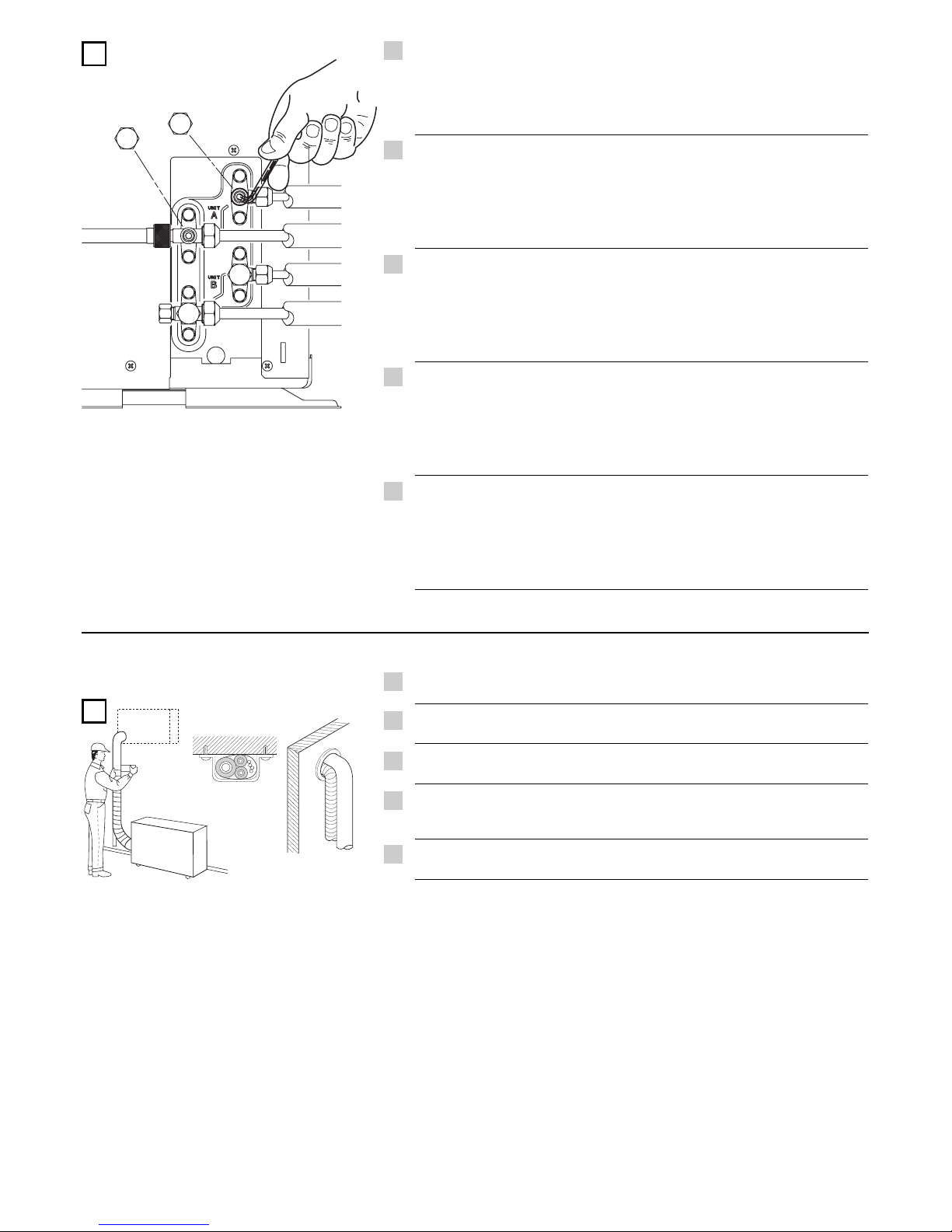
With vacuum pump still running close the low pressure knob on valve manifold.
Then stop vacuum pump. Using an hexagonal key, open the service valve on
small tube, then close it after 10 seconds. Check tightness of all joints using
liquid soap.
Con la pompa del vuoto in funzione chiudere il rubinetto del gruppo manometrico
(bassa pressione). Quindi fermare la pompa del vuoto. Con una chiave esagonale,
aprire la valvola del tubo piccolo per 10 secondi quindi richiuderla; verificare la
tenuta di tutti i giunti con sapone liquido.
Quand la pompe à vide est en fonction, fermer la vanne de «basse pression»
du groupe manométrique. Ensuite arrêter la pompe à vide. Avec une clé
héxagonale, ouvrir la vanne du petit tube pendant 10 secondes et ensuite la
fermer; vérifier l'étanchéité de tous les joints au moyen de savon liquide.
Mit der arbeitenden Vakuum-Pumpe den Hahn des manometrischen Aggregats
(Niederdruck) zudrehen. Die Pumpe abstellen. Mit einem
Sechskanteinsteckschlüssel das Ventil auf dem kleinen Rohr aufdrehen und es
nach 10 Sek. zudrehen. Die Dichtigkeit aller Kupplungen durch flüssige Seife
überprüfen.
Mientras se encuentra en funcionamiento la bomba de vacío, cerrar el «mando
de baja presión» del grupo manométrico. Luego parar la bomba de vacío.
Mediante una llave hexagonal, abrir la válvula del tubo pequeño durante 10
segundos y después cerrarla; comprobar la estanqueidad de todas las juntas
utilizando jabón líquido.
I
EG
F
D
E
L
Page 28

12
Wide tube service
valve (3-way)
Action
Narrow tube service
valve (2-way)
Shipping
Spedizione
Transport
Versand
Envío
Operating and test running the air conditioner
Funzionamento e prova del condizionatore
Fonctionnement et essai de fonctionnement
du climatiseur
Betrieb und Probelauf der Klimaanlage
Funcionamiento y prueba del acondicionador
Measuring pressure and gas charging
Misurazione pressione e caricamento gas
Mesurer la pression et charger en gaz
Druckmessung und Gasladung
Medición de la presión y de la carga de gas
Air purging with a vacuum pump
Spurgo aria con pompa del vuoto
Purge de l'air avec une pompe à vide
Ausblasung der Luft mit einer Vakuumpumpe
Limpieza del aire con la bomba de vacío
The service port on the wide tube service valve uses a Schrader core valve to
access the refrigerant system. Therefore, be sure to use a hose connector which
has a push-pin inside.
La valvola di servizio del rubinetto dell'unità esterna da utilizzare per il vuoto
del sistema, ripristino carica refrigerante e misurazione della pressione di esercizio
è del tipo "Schrader". Utilizzare un attacco pompa del vuto di tipo a spillo.
La vanne de service de l'unité extérieure sur laquelle on peut se connecter pour
vider le circuit frigorifique, rajouter du réfrigérant et mesurer la pression de
fonctionnement, est du type "Schrader". Utilisez un raccord avec poussoir de valve.
Für den Zugriff auf das Kühlmittelsystem und für die Betriebsdruckmessung
benutzt das Serviceventil des Absperrhahns des großen Rohres ein Schrader
Kernventil. Ihr Vakuumschlauchverbindungstück sollte über einen Druckstift
verfügen.
La válvula de servicio de la unidad exterior donde se realiza la conexión para
vaciar el sistema, Ilenar con refrigerante y medir la presión de frabajo es del tipo
"Schrader" (pistón con muelle antiretorno). Utilizar un acoplamiento para la
bomba de vaciado, adecuado para este tipo de válvula.
BASIC FUNCTIONS OF THE SERVICE V ALVES •
FUNZIONI PRINCIP ALI DELLE VALVOLE
• FONCTIONS DE BASE
DE VALVES DE SERVICE •
FUNKTION DER ABSPERRVENTILE
• PRINCIPALES FUNCIONES DE LAS VALVULAS
I
EG
F
D
E
CLOSED
CLOSED
OPEN
OPEN
O-ring
Valve cap
Stem
Page 29
13
M
Turn the service valves stem in counterclockwise to fully open the valves. At
this point vacuum pump flexible hose can be disconnected. Replace bonnet
and flare nut, tighten them to 200 kg/cm with a torque wrench.
Repeat what described from K to M for the second circuit. The two indoor units
have to be marked has “indoor unit A” and “indoor unit B”. Be sure that the
idraulic connection to indoor unit Aor B corrisponds to its own electrical connection.
Aprire completamente le valvole di servizio (senso antiorario). A questo punto
scollegare il flessibile della pompa del vuoto. Rimontare i cappucci ed il
bocchettone, stringere con momento torcente di 200 kg/cm.
Le operazioni descritte dalla lettera K alla lettera M vanno ripetute per il secondo
circuito. Le due unità interne vanno contraddistinte in unità interna A ed unità
interna B. Verificare che il collegamento idraulico all’unità interna Ao B corrisponda
il suo corretto collegamento elettrico.
Ouvrir complètement les vannes de service (dans le sens contraire des aiguilles
d'une montre). Ace moment, enlever le flexible de la pompe à vide. Reviser les
bouchons et serrer (200 kg/cm).
Répéter les operations déscrites de la lettre K à la lettre M pour le deuxième circuit.
On doit marquer les deux unités intérieures en “unité intérieure A” et “ unité
intérieure B”. Vérifier que le racordement hydralique à l’unité intérieure Aou B
corrépond son correct branchement électrique.
Die Ventile gänzlich aufdrehen (im Gegenuhrzeigersinn). Den Schlauch der
Vakuum-Pumpe ausschalten. Die Ventilverschlüsse und den Stutzen wieder
anbringen. Mit Drehmoment bei 200 Kg./cm. anziehen.
Das Verfahren von K bis M für den zweiten Kreis wiederholen. Die zwei
Inneneinheiten sollen durch “Inneneinheit A” und “Inneneinheit B” gekennzeichnet
werden. Vergewissem Sie sich, daß die hydraulische Verbindung der Inneneinheit
A oder B seinem elektrischen Anschaltung entspricht.
Abrir completamente las válvulas de servicio (sentido contrario a las agujas del
reloj). Aeste punto desconectar el flexible de la bomba de vacío. Volver a montar
los capuchones y la tuerca-tapón (200 kg/cm).
Las operaciones descritas desde la K hasta la M deben ser repetidas para el
segundo circuito. Llamar unidad interna Ay unidad interna B a las dos unidades
internas. Comprobar que el empalme hidràulico de las unidades internas Ao B
le corrisponda su conexiòn eléctrica correcta.
N
Complete insulation of refrigerant tubes; wrap with armoning tape. Fix and
support tubes with brackets. Seal hole in the wall, if necessary.
Completare l'isolamento, proteggere con nastratura, fissare e supportare con
staffe; se necessario sigillare il foro di passaggio nel muro.
Compléter l'isolation, des tubes, les protéger avec des rubans les, fixer avec des
brides; si nécessaire, boucher le trou de passage dans le mur.
Die Röhre mit zweckgemäßem Isolierungsmaterial gut isolieren, an der Wand
mit Klammern fest klemmen und, wenn nötig, das Loch in der Wand mit
Dichtungsmasse füllen.
Completar el aislamiento, proteger con cinta, fijar y poner abrazaderas de
soporte; si fuera necesario, sellar el orificio de paso de la pared.
I
EG
F
D
E
I
EG
F
D
E
Page 30

14
OUTDOOR/INDOOR UNIT REFRIGERANT CIRCUIT ADDRESS •
INDIRIZZO CIRCUITO REFRIGERANTE UNITA’
ESTERNA/INTERNA
• ADRESSE DU CIRCUIT DE REFRIGERATION UNITE EXTERIEURE/INTERIEURE •
AUSSEN/
INNENEINHEIT-
KÜHLROHRE ADRESSE
• DIRECCION DEL CIRCUITO DE REFRIGERACIÓN UNIDAD
EXTERIOR/INTERIOR
BEFORE STARTING THE SYSTEM, IT IS NECESSAR YTO SET THE REFRIGERANT CIRCUIT
ADDRESSES.
THE SETTING HAS TO BE MADE ON THE INDOOR UNITS AND FOR EACH INDOOR UNIT
OF THE SYSTEM.
FOR THE SETTING, SEE THE INSTALLATION MANUAL OF THE SPECIFIC INDOOR UNIT .
PRIMA DI AVVIARE IL SISTEMA, E’ NECESSARIO IMPOSTARE GLI INDIRIZZI CIRCUIT O
REFRIGERANTE.
L’IMPOSTAZIONE VAFATTA SULLE UNIT A’ INTERNE E PER OGNI UNITA’ INTERNA DEL
SISTEMA.
PER L’IMPOSTAZIONE, VEDI IL MANUALE INSTALLAZIONE DELL’UNITA’ INTERNA
SPECIFICA.
AVANT DE DEMARRER LE SYSTEME, ON FAUT REGLER LES ADRESSES DU CIRCUIT
DE REFRIGERATION.
LE REGLAGE DOIT ETRE EFFECTUE SUR LES UNITES INTERIEURES ET POUR CHAQUE
UNITE INTERIEURE DU SYSTEME.
POUR LE REGLAGE, VOIR LA NOTICE D’INSTALLATION DE L’UNITE INTERIEURE
SPECIFIQUE.
VOR DEM START DES SYSTEM, MUSSEN SIE DIE KÜHLROHRE ADRESSEN EINSTELLEN.
DIE EINSTELLUNG MUSS AUF DER INNENEINHEITEN UND FUR JEDE INNENEINHEIT DES
SYSTEMS GEMACHT WERDEN.
F
Ü
R DIE EINSTELLUNG, SEHEN SIE DIE INSTALLATIONSANLEITUNGEN DER
JEWEILIGEN INNENEINHEIT.
ANTES DE ARRANCAR EL SISTEMA, ES NECESARIO REGULAR LAS DIRECCIONES
DEL CIRCUITO DE REFRIGERACIÓN.
LA REGULACI
Ó
N DEBE REALIZARSE EN LAS UNIDADES INTERIORES Y PARA CADA
UNIDAD INTERIOR DEL SISTEMA.
PARA LA REGULACI
Ó
N, VER LAS INSTRUCCIONES DE INSTALACIÓN DE LA UNIDAD
INTERIOR ESPECIFICA.
ATTENZIONE
CAUTION
ATTENTION
VORSICHT
ATENCION
ADDRESSING EXAMPLE - ESEMPIO DI INDIRIZZAMENTO - EXEMPLE D’ADRESSAGE ADRESSIERUNG BEISPIEL - EJEMPLO DE DIRECCIONAMIENTO
ADDRESS B
ADDRESS A
OUTDOOR UNIT INDOOR UNITS
Page 31

15
Pump down means collecting all refrigerant gas in the system back into
the outdoor unit without losing gas. Pump down is used when the unit is
to be moved of before servicing the refrigerant circuit.
Pump down significa recuperare tutto il gas refrigerante nell’Unità Esterna
senza perdere la carica del sistema. Serve quando si deve riposizionare
il condizionatore e per interventi di riparazione sul circuito frigorifero.
Pump down signifie récupérer tout le gaz réfrigérant dans l'unité extérieure
sans perdre la charge du système. Il sert quand on doit déplacer le
climatiseur, et pour les interventions de réparation au circuite frigorifique.
Das bedeutet: das Kühlmittel in die Außeneinheit ohne Gas-Verlust
zurückzugewinnen. Man benutzt es, wenn das Klimagerät in eine neue
Position gestellt werden muß oder der Kühlmittelkreislauf Verbesserung
braucht.
“Pump down” significa: recuperar todo el gas refrigerante en la Unidad
Exterior sin perder la carga del Sistema. Se utiliza cuando hay que recolocar
el acondicionador, y después de una reparación del circuito de refrigeración.
PUMP DOWN
PUMP DOWN PROCEDURE •
PROCEDIMENTO PUMP DOWN
• PUMP DOWN PROCEDURE •
PUMP-DOWN-VERFAHREN
• PROCEDIMIENTO PUMP DOWN
Connect a valve manifold to the charge port on a wide tube service valve, partially open
it (1/4 turn). Let the air purge from the manifold. Fully close the narrow tube service
valves all the way.
Collegare un gruppo manometrico a una valvola della bassa pressione, aprirla parzialmente
(1/4 di giro). Spurgare l'aria dal manometro. Chiudere completamente le valvole alta pressione.
Relier un groupe manométrique à une vanne de basse pression, l'ouvrir partiellement (1/4
de tour). Purger l'air du manomètre. Fermer complètement les vannes de haute pression.
Ein manometrisches Aggregat mit einem Niederdruck-Ventil verbinden (1/4 Umdrehung).
Die Luft vom Druckmesser abblasen. Die Hochdruck-Ventile zudrehen.
Conectar el grupo manométrico a una válvula de baja presión, abrirla parcialmente (1/4
vuelta). Purgar el aire del manómetro. Cerrar completamente las válvulas de alta presión.
Remove the valve manifold. At that time, PUMP DOWN has been completed and all
refrigerant gas will have been collected in the outdoor unit.
Rimuovere il gruppo manometrico. A questo punto l'operazione di PUMP DOWN é
completa poiché tutto il gas refrigerante é raccolto nell'unità esterna.
Enlever le groupe manométrique. Ace moment l'operation de PUMP DOWN est achevée,
car tout le gaz réfrigérant se trouve dans l'unité extérieure.
Das manometrische Aggregat entfernen. Jetzt ist die PUMPDOWN-Phase aus, weil das
ganze Kühlmittel in der Außeneinheit zurückgewonnen worden ist.
Desconectar el grupo manométrico. La operación de PUMP DOWN se ha completado,
dado que todo el gas refrigerante se encuentra recogido en la unidad exterior.
B
Turn on the unit's operating switch and start cooling operation. When the low-pressure
gauge reading falls to 1 to 0,5 Kg/cm2, fully close the wide tube valves and then quickly
turn off the unit.
Avviare il condizionatore in raffreddamento. Quando la pressione letta sul manometro
scende ad un valore compreso tra 1 e 0,5 Kg/cm2, chiudere completamente le valvole
bassa pressione e spegnere il condizionatore.
Faire démarrer le climatiseur en mode de refroidissement. Quand la pression lue sur le
manomètre descend à une valeur entre 1 et 0,5 kg/cm2, fermer complètement les vannes
de basse pression et arréter le climatiseur.
Das Klimagerät in Betriebsart Kühlung einschalten. Wenn der vom Druckmesser angezeigte
Druck einen Wert zwischen 1 und 0,5 Kg./cm2erreicht, drehen Sie die NiederdruckVentile zu und schalten Sie das Klimagerüt aus.
Poner en marcha el acondicionador en enfriamiento. Cuando la presión leída en el
manómetro baja hasta un valor comprendido entre 1 y 0,5 kg/cm
2
, cerrar completamente
las válvulas de baja presión y apagar el acondicionador.
C
I
EG
F
D
E
I
EG
F
D
E
I
EG
F
D
E
I
EG
F
D
E
A
Page 32

EG
I
F
D
E
P
GR
BLK BLACK
NERO
NOIR
SCHWARZ
NEGRO
PRETO
MAURO
BLU BLUE
BLU
BLEU
BLAU
AZUL
AZUL
MPLE
BRN BROWN
MARRONE
MARRON
BRAUN
MARRÓN
CASTANHO
KAFE
GRN / YEL GREEN / YELLOW
VERDE / GIALLO
VERT / JAUNE
GRÜN / GELB
VERDE / AMARILLO
VERDE / AMARELO
PRASINO É KITRINO
GRY GREY
GRIGIO
GRIS
GRAU
GRIS
CINZENTO
GKRIZO
ORG ORANGE
ARANCIONE
ORANGE
ORANGE
NARANJA
COR-DE-LARANJA
PORTOKALI
PNK PINK
ROSA
ROSE
ROSA
ROSA
COR-DE-ROSA
ROZ
RED RED
ROSSO
ROUGE
ROT
ROJO
ENCARNADO
KOKKINO
VLT VIOLET
VIOLA
VIOLET
VIOLETT
VIOLETA
VIOLETA
MWB
WHT WHITE
BIANCO
BLANC
WEISS
BLANCO
BRANCO
ASPRO
YEL YELLOW
GIALLO
JAUNE
GELB
AMARILLO
AMARELO
KITRINO
SYMBOL EG
I
F
D
E
P
GR
CCH CRANK CASE HEATER
RISCALDATORE CARTER
RESISTANCE DE CARTER-MOTEUR
KURBELGEHÄUSEHEIZUNG
CALENTADOR DELCÁRTER
AQUECEDOR DO CÁRTER
QERMASTHS STROFALOQALAMOU
CM COMPRESSOR MOTOR
MOTORE COMPRESSORE
MOTEUR DE COMPRESSEUR
KOMPRESSORMOTOR
MOTOR DEL COMPRESOR
COMPRESSOR
SUMPIESTHS
C1, 2, 3 CAPACITOR
CONDENSATORE
CONDENSATEUR
KONDENSATOR
CONDENSADOR
CONDENSADOR
SUMPUKNWTHS
DEF THERMO DEFROST THERMOSTAT
TERMOSTATO SBRINATORE
THERMOSTAT DE DEGIVRAGE
ENTFROSTER-THERMOSTAT
TERMOSTATO DE DESCONGELACION
TERMOSTATO DE DESCONGELAÇAO
QERMOSTATHS APOYUXHS
FLP FLAP MOTOR
MOTORE DEFLETTORE
MOTEUR DE VOLET
KLAPPENMOTOR
MOTOR DEL DEFLECTOR
MOTOR DA PLACA
KINHTRAS PTERUGIOU
LM LOUVER MOTOR
MOTORE DEFLETTORE
MOTEUR D’AUVENT
LUFTKLAPPENMOTOR
MOTOR CON ABERTURAS
MOTOR COM ABERTURAS LATERAIS
KINHTHRAS GRILLIAS
FM OUTDOOR FAN MOTOR
MOTORE ESTERNO VENTOLA
MOTEUR DE VENTILATEUR EXTERIEUR
AUSSENLÜFTERMOTOR
MOTOR EXTERIOR DE LATURBINA
MOTOR DA VENTOINHA EXTERIOR
EXWTERIKOS ANEMISTHRAS
FMI INDOOR FAN MOTOR
MOTORE INTERNO VENTOLA
MOTEUR DE VENTILATEUR INTERIEUR
INNENLÜFTERMOTOR
MOTOR INTERIOR DE LATURBINA
MOTOR DA VENTOINHA INTERIOR
ESWTERIKOS ANEMISTHRAS
REC. ASSY RECEIVER ASSY
GRUPPO RICEVITORE
ENSEMBLE RECEPTEUR
EMPFÄNGER-BAUGRUPPE
GRUPO RECEPTOR
GRUPO RECEPTOR
SET DEKTH
MG MAGNETIC CONTACTOR
CONTATTORE MAGNETICO
CONTACTEUR MAGNETIQUE
MAGNETKONTGEBER
CONTACTOR MAGNÉTICO
CONTADOR MAGNÉTICO
MAGNHTIKOS DIAKOPTHS
NF NOISE FILTER
FILTRO RUMORE
FILTRE ANTI P ARASSITE
LÄRMSCHUTZFILTER
FILTRO DELRUIDO
FILTRO DE RUÍDO
FILTRO QORUBOU
OLR OVERLOAD RELAY
RELÉ SOVRACCARICO
RELAIS DE SURCHARGE
ÜBERLASTRELAIS
RELÉ DE SOBRECARGA
RELÉ DE SOBRECARGA
RELE UPERFORTWSHS
PCB1, 2 CONTROLLER
SCHEDA ELETTRICA
CARTE ELECTRONIQUE
STEUERGERÄT
CONTROLADOR
PAINELELÉTRICO
ELEGKTHS
PR POWER RELAY
RELÉ ALIMENTAZIONE
RELAIS D’ALIMENTATION
LEISTUNGSRELAIS
RELÉ DE ALIMENTACIÓN
RELÉ DAALIMENTAÇAO
RELE ISCUOS
RY RELAY
RELÉ
RELAIS
RELAIS
RELÉ
RELÉ
RELE
SSR SOLID STATE RELAY
RELÉ STATO SOLIDO
RELAIS A SEMI-CONDUCTEUR
FESTKÖRPERRELAIS
RELÉ DEL ESTADO SÓLIDO
RELÉ DO ESTADO SÓLIDO
RELE STEREAS KATASTASHS
SR STARTING RELAY
RELÉ DI AVVIAMENTO
RELAIS DE DEMARRAGE
STARTRELAIS
RELÉ DE ARRANQUE
RELÉ DE ARRANQUE
RELE EKKINHSIS
SV SOLENOID VALVE
VALVOLA SOLENOIDE
ELECTROVANNE
MAGNETVENTIL
VÁLVULASOLENOIDE
VÁLVULASOLENÓIDE
SWLHNOEIDHS BALBIDA
SW. ASSY SWITCH ASSY
GRUPPO INTERRUTTORI
ENSEMBLE INTERRUPTEUR
SCHALTER-BAUGRUPPE
GRUPO DE INTERRUPTORES
GRUPO INTERRUPTOR
SET DIAKOPTH
THERMO THERMOSTAT
TERMOSTATO
THERMOSTAT
THERMOSTAT
TERMOSTATO
TERMOSTATO
QERMOSTATHS
TC, TOA THERMISTOR
TERMISTORE
THERMISTANCE
THERMISTOR
TERMISTOR
TERMISTOR
QERMOSTISTATHS
TP TERMINAL PLATE
PIASTRA TERMINALI
BORNIER
KLEMMENPLATTE
PLACA DE LOS TERMINALES
TERMINAL
AKRODEKTHS
TR1 POWER TRANSFORMER
TRASFORMATORE DI POTENZA
TRANSFORMATEUR DE PUISSANCE
NETZTRANSFORMATOR
TRANSFORMADOR DE POTENCIA
TRANSFORMADOR DE CORRENTE
METASHMATISTHS ISCUOS
RV 4-WAY VALVE
VALVOLA 4 VIE
VANNE 4 VOIES
4-WEG-VENTIL
VÁLVULADE 4 VÍAS
VÁLVULADE 4 VIAS
BALBIDA 4 DIEUQUNSEXWN
47C NEGATIVE PHASE RELAY
RELÉ A FASE NEGATIVA
RELAIS D’ORDRE DE PHASE
NEGATIVPHASENRELAIS
RELÉ DE FASE NEGATIVA
RELÉ DA FASE NEGATIVA
RELE ARNHTIKHS FASHS
Electric wiring diagrams’ symbols /
Simboli schemi elettici
/ Symboles des schemas électriques /
Symbole der System-Schaltplanen
Símbolos de los esquemas eléctricos /
Símbolos
dos esquemas elétricos /
SSuummbblloovvllwwnn HHLLEEKKTTRRIIKKOO DDIIAAGGRRAAMMMMAA TTWWNN SSUUSSTTHHMMAATTWWNN
Wires color legend
Legenda colori fili elettrici
Légende des couleurs des fils électriques
Beschriftung der Leitungs-Farben
Leyenda de los colores de los cable electricos
Legenda das côres dos fios elétricos
PPiinnaakkaa"" ccrrwwmmaavvttwwnn hhlleekkttrriikkwwvvnn kkaallwwddiivvwwnn
S.A.C. - Printed in italy
Z.I. Route départementale 28
01600 Reyrieux France
Tél. 33 4 74 00 92 92 - Fax 33 4 74 00 42 00
Technibel is a trademark of NIBE ENERGY SYSTEM FRANCE
 Loading...